EP2570706A1 - Brush seal - Google Patents
Brush seal Download PDFInfo
- Publication number
- EP2570706A1 EP2570706A1 EP12181309A EP12181309A EP2570706A1 EP 2570706 A1 EP2570706 A1 EP 2570706A1 EP 12181309 A EP12181309 A EP 12181309A EP 12181309 A EP12181309 A EP 12181309A EP 2570706 A1 EP2570706 A1 EP 2570706A1
- Authority
- EP
- European Patent Office
- Prior art keywords
- annular
- clamping
- brush seal
- surface feature
- bristle pack
- Prior art date
- Legal status (The legal status is an assumption and is not a legal conclusion. Google has not performed a legal analysis and makes no representation as to the accuracy of the status listed.)
- Withdrawn
Links
- 238000000926 separation method Methods 0.000 claims abstract description 24
- 230000003247 decreasing effect Effects 0.000 claims abstract description 7
- 238000012856 packing Methods 0.000 description 17
- 239000000835 fiber Substances 0.000 description 3
- 238000007789 sealing Methods 0.000 description 3
- 230000001154 acute effect Effects 0.000 description 1
- 230000015572 biosynthetic process Effects 0.000 description 1
- 230000007423 decrease Effects 0.000 description 1
- 230000000694 effects Effects 0.000 description 1
- 238000004519 manufacturing process Methods 0.000 description 1
- 238000004886 process control Methods 0.000 description 1
Images

Classifications
-
- F—MECHANICAL ENGINEERING; LIGHTING; HEATING; WEAPONS; BLASTING
- F16—ENGINEERING ELEMENTS AND UNITS; GENERAL MEASURES FOR PRODUCING AND MAINTAINING EFFECTIVE FUNCTIONING OF MACHINES OR INSTALLATIONS; THERMAL INSULATION IN GENERAL
- F16J—PISTONS; CYLINDERS; SEALINGS
- F16J15/00—Sealings
- F16J15/16—Sealings between relatively-moving surfaces
- F16J15/32—Sealings between relatively-moving surfaces with elastic sealings, e.g. O-rings
- F16J15/3268—Mounting of sealing rings
-
- F—MECHANICAL ENGINEERING; LIGHTING; HEATING; WEAPONS; BLASTING
- F16—ENGINEERING ELEMENTS AND UNITS; GENERAL MEASURES FOR PRODUCING AND MAINTAINING EFFECTIVE FUNCTIONING OF MACHINES OR INSTALLATIONS; THERMAL INSULATION IN GENERAL
- F16J—PISTONS; CYLINDERS; SEALINGS
- F16J15/00—Sealings
- F16J15/16—Sealings between relatively-moving surfaces
- F16J15/32—Sealings between relatively-moving surfaces with elastic sealings, e.g. O-rings
- F16J15/3284—Sealings between relatively-moving surfaces with elastic sealings, e.g. O-rings characterised by their structure; Selection of materials
- F16J15/3288—Filamentary structures, e.g. brush seals
Definitions
- the present invention relates to brush seals, which may be in strip form for linear sealing applications, or in annular form for circular and non circular sealing applications.
- Brush seals are used in many industries and commonly take the form of a pair of clamping plates between which is clamped a bristle pack.
- the clamping plates may be of different heights, providing different levels of support to the bristles depending on the direction of application of force.
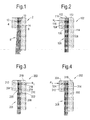
- a section through a conventional annular brush seal 2 is illustrated in Figure 1 .
- the seal 2 comprises a first annular clamp plate 4, a second annular clamp plate 6 and a bristle pack 8 sandwiched between the plates 4, 6.
- a circumferential weld 10 is applied around the outer circumference of the seal 2 to attach the bristle pack 8 firmly to the first and second plates 4, 6.
- the clamping plates 4, 6 each comprise an opposed clamping surface 12, 14, that contacts the bristle pack 8 and over which a clamping force is applied to hold the bristle pack 8 in place.
- the clamping surfaces 12, 14 are planar and parallel, resulting in a substantially constant separation between the surfaces across the entire clamped region of the bristle pack 8.
- one of the first and second plates 4, 6, may be deeper in a bristle direction than the other of the plates, such that the bristle pack 8 is supported along a greater extent of its height on one side.
- the second plate 6 is deeper than the first plate 4, providing additional support to the bristle pack 8 on the right side of the bristle pack, as seen in the Figure.
- FIG. 1 is also representative of a linear brush seal having rectangular clamping plates 4, 6 and a linear bristle pack and outer edge weld.
- the bristle pack 8 may contain a great number of individual bristles, and the packing arrangement of the bristles may vary across the clamped region of the bristle pack. Such variations in packing arrangement can impact upon the clamping load experienced across the bristle pack 8. The result is a bristle loading pattern that varies in an uncontrolled manner across the clamping region, with regions of maximum clamping load, where the bristles of the bristle pack are strongly constrained and unable to move, and regions of lesser loading, where some movement of the bristles is possible.
- the present invention seeks to address some or all of the above mentioned disadvantages.
- annular brush seal comprising first and second annular clamp plates, each clamp plate comprising an opposed annular clamping surface, and a pack of radially extending bristles clamped between the clamping surfaces of the clamp plates, wherein the clamping surface of at least one of the clamp plates is profiled, such that a separation between the clamping surfaces increases with decreasing radius.
- the clamping surface may be profiled such that separation between the clamping surfaces is inversely proportional to radius. In this manner, it may be ensured that the cylindrical packing area available to the bristles remains substantially constant with changing radial location.
- Both clamping surfaces may be profiled, the two profiles cooperating to provide the desired relationship between separation and radial location.
- the profiled clamping surface may further comprise an annular surface feature causing a step change in the profile of the surface.
- a step change in the surface profile causes a corresponding step change in the load experienced by the bristle pack, thus providing a defined radial location of maximum loading.
- the annular surface feature may comprise an annular shoulder.
- the annular shoulder may be arranged such that the step change in surface profile causes a step increase in clamping surface separation with a reduction in radius.
- the annular surface feature may comprise an annular protrusion, such as an annular rib formed on the clamping surface.
- the annular surface feature may comprise an annular recess.
- the annular recess may extend past a radially inner edge of a clamped region of the bristle pack.
- the annular surface feature may comprise a cooperating protrusion and recess.
- the recess may be located on a radially inner side of the protrusion.
- a brush seal comprising first and second clamp plates, each clamp plate comprising an opposed clamping surface, and a bristle pack clamped between the clamping surfaces of the clamp plates, wherein the clamping surface of at least one of the clamp plates comprises a linear surface feature extending across the clamping surface and causing a step change in the profile of the clamping surface.
- a step change in the clamping surface causes a corresponding step change in the load experienced by the bristle pack, thus providing a defined radial location of maximum loading.
- the linear surface feature may extend across the clamping surface substantially to the full extent of the bristle pack clamped between the clamping surfaces.
- the surface feature may comprise an integral feature of the clamp plate.
- the surface feature may comprise a separate component cooperating with the clamp plate.
- the surface feature may comprise a shoulder.
- the shoulder may be arranged such that the step change in surface profile causes a step increase in clamping surface separation in a direction towards the free ends of the bristles.
- the surface feature may comprise a protrusion, such as a rib formed on the clamping surface.
- the surface feature may comprise a recess.
- the recess may extend past an inner edge of a clamped region of the bristle pack.
- the surface feature may comprise a cooperating protrusion and recess.
- the recess may be located on an inner side of the protrusion.
- the brush seal may comprise an annular seal.
- the clamp plates may comprise annular clamping surfaces and the surface feature may comprise an annular surface feature.
- the present invention addresses the disadvantages of the prior art in two ways.
- the increased packing density experienced at radially inner locations of annular seals is addressed by profiling the clamping surface or surfaces, such that separation of the clamping surfaces varies inversely with radius, providing a substantially constant cylindrical packing area.
- This profiling may be combined with, or as an alternative to, a step change in the clamping surface, caused for example by a shoulder, recess or protrusion.
- Such a step change in clamping surface causes a corresponding step change in clamping force experienced by the bristle pack, hence defining a precise radial location for maximum axial loading.
- This location is then the location at which the bristles become fixed, and defines the effective length of the bristles. In this manner, variation in bristle free lengths is minimised and a more repeatable bristle clamping position is established.
- Aspects of the present invention thus allow for consistent and repeatable bristle pack behaviour around a single seal and between different seals.
- a first embodiment of the present invention comprises an annular brush seal 102 having a first annular clamp plate 104, a second annular clamp plate 106 and a bristle pack 108 sandwiched between the plates 104, 106.
- a circumferential weld 110 is applied around the outer circumference of the seal 102 to attach the bristle pack 108 firmly to the first and second plates 104, 106.
- the clamping plates 104, 106 each comprise an opposed clamping surface 112, 114, that contacts the bristle pack 108 and over which a clamping force is applied to hold the bristle pack 108 in place.
- the clamping surfaces 112, 114 are planar and parallel.
- a first one of the clamping surfaces 112 comprises an annular recess 116 that commences at a shoulder 118 and extends from the shoulder 118 to the radially inner edge 120 of the clamping surface 112.
- the separation between the clamping surfaces 112, 114 is thus increased by the depth of the recess over the annular area of the recess. Consequently, the clamping force experienced by the bristle pack is reduced over this annular area.
- the maximum clamping force experienced by the bristle pack 108 is at the radial location of the shoulder 118 at which the recess commences. This is illustrated on the Figure as R 1 . At this radial location, the bristles in the bristle pack become fixed, and the effective length of the bristle pack may thus be measured from this radial location.
- FIG. 3 Another embodiment of the present invention is illustrated in Figure 3 .
- the seal 202 comprising first and second annular clamp plates 204, 206 and a bristle pack 208 sandwiched between the plates 204, 206.
- a circumferential weld 210 is applied around the outer circumference of the seal 202.
- the clamping plates 204, 206 each comprise an opposed clamping surface 212, 214, that contacts the bristle pack 208 and over which a clamping force is applied to hold the bristle pack 208 in place.
- an annular recess 218 is formed on a second one of the clamping surfaces 216.
- the recess 216 commences at an annular shoulder 218 and extends radially inwardly past the radially inner extent 220 of the first clamping surface 214.
- the recess 216 performs a similar function to the recess 116 of the embodiment of Figure 2 , effecting a step change in the clamping force experienced by the bristle back 208 and defining a radial location for maximum loading at the radially outer shoulder 218 where the recess commences.
- This radial location illustrated as R 2 on the Figure, is the location at which the bristles in the bristle pack become fixed, and the effective length of the bristle pack may thus be measured from this radial location.
- the recess 216 may continue to the radially inner extent of the second clamping surface 214, or may terminate at a second radially inner shoulder 222. As illustrated in the Figure, the radially inner shoulder 222 is positioned radially inward of the radially inner extent of the first clamping surface 212, such that the separation between the clamping surfaces remains constant radially inward of the first shoulder 218.
- Figure 4 illustrates another embodiment of the present invention, in which a defined radial location for maximum loading is provided by an annular rib or protrusion 324 formed on the first clamping surface 312.
- the seal 302 of Figure 4 comprises first and second clamping plates 304, 306 having opposed clamping surfaces 312, 314 and sandwiching a bristle pack 308 therebetween.
- An annular weld 310 extends around the outer circumference of the seal 302.
- An annular rib 324 protrudes from a first one of the clamping surfaces 312, providing a step change in the separation between the clamping surfaces 312, 314 at the radial location of the rib 324.
- This step change corresponds to a step increase in the clamping load experienced by the bristle pack 308, and hence provides a defined radial location for maximum axial loading experienced by the bristle pack 308.
- This radial location illustrated as R 3 on the Figure, is the location at which the bristles in the bristle pack become fixed, and the effective length of the bristle pack may thus be measured from this radial location.
- annular rib of the embodiment of Figure 4 may be formed on either the first or the second clamp plate, and may optionally be combined with the recess of Figure 3 .
- the embodiment of seal 402 shown in Figure 5 comprises first and second clamping plates 404, 406 having opposed clamping surfaces 412, 414 and sandwiching a bristle pack 408 therebetween.
- An annular weld 410 extends around the outer circumference of the seal 402.
- An annular rib 424 protrudes from a second one of the clamping surfaces 414, providing a step change in the separation between the clamping surfaces 412, 414 at the radial location of the rib 424.
- the rib 424 is combined with a recess 416, formed radially inwards of the rib 424 and extending radially inwardly past the radially inner extent 420 of the first clamping surface 414.
- the step change in separation between the clamping surfaces caused by the cooperating rib 424 and recess 416 corresponds to a step change in the clamping load experienced by the bristle pack 408.
- This change thus provides a defined radial location for maximum axial loading experienced by the bristle pack 408.
- This radial location illustrated as R 4 on the Figure, is the location at which the bristles in the bristle pack become fixed, and the effective length of the bristle pack may thus be measured from this radial location.
- the present invention also provides for the establishment of a uniform clamping load in an annular brush seal by profiling one or both of the clamping surfaces.
- a seal embodying this concept is illustrated in Figure 6 .
- the seal 502 comprises a first annular clamp plate 504, a second annular clamp plate 506 and a bristle pack 508 sandwiched between the plates 504, 506.
- a circumferential weld 510 is applied around the outer circumference of the seal 502 to attach the bristle pack 508 firmly to the first and second plates 504, 506.
- the clamping plates 504, 506 each comprise an opposed clamping surface 512, 514, that contacts the bristle pack 508 and over which a clamping force is applied to hold the bristle pack 508 in place.
- a first one of the clamping surfaces 512 is profiled, such that the separation between the clamping surfaces increases with decreasing radius.
- the profile of the first clamping surface 412 is idealised to provide an inversely proportional relationship between separation of the clamping surfaces and radius. Such a relationship allows for the cylindrical packing area available to the bristle pack 508 to remain substantially constant, even as the radial location under consideration changes.
- a bristle pack must be forced into a cylindrical packing area that decreases towards the radially inner edge of the seal.
- the cylindrical packing area may remain constant with changing radius, owing to the clamping plate profiling that results in a relationship between separation s and radius r of: s ⁇ 1 r
- Figure 7 illustrates a seal 602 in which the profiled clamping surface of the embodiment of Figure 6 is combined with the recess of Figure 2 .
- the seal 602 of Figure 7 comprises a first annular clamp plate 604, a second annular clamp plate 606 and a bristle pack 608 sandwiched between the plates 604, 606.
- a circumferential weld 610 is applied around the outer circumference of the seal 602 to attach the bristle pack 608 firmly to the first and second plates 604, 606.
- the clamping plates 604, 606 each comprise an opposed clamping surface 612, 614, that contacts the bristle pack 608 and over which a clamping force is applied to hold the bristle pack 608 in place.
- a first one of the clamping surfaces 612 is profiled, such that the separation between the clamping surfaces increases with decreasing radius. The profile preferably allows for an approximately inversely proportional relationship between the separation of the clamping surfaces and the radial location at which the separation is measured.
- the first one of the clamping surfaces 612 further comprises an annular recess 616 that commences at a shoulder 618 and extends from the shoulder 618 to the radially inner edge 620 of the clamping surface 612.
- the shoulder 618 at which the recess commences causes a step change in the clamping surface separation, and hence a step reduction in the clamping force experienced by the bristle pack 608 over the annular area of the recess.
- the maximum clamping force experienced by the bristle pack 608 is at the radial location of the shoulder 618 at which the recess commences. This is illustrated on the Figure as R 6 . At this radial location, the bristles in the bristle pack become fixed, and the effective length of the bristle pack may thus be measured from this radial location.
- the present invention thus addresses the key areas of bristle free length variability and weld process control, allowing for the formation of repeatable bristle packs, with little variation around a single part and also from part-to-part.
- the invention may be applied to circular or non circular seals.
- the invention may also be applied to brush seal strips for linear sealing problems where a defined bristle or fibre length is necessary to reduce or remove variability in seal performance.
- the invention may be employed in any application where free fibre or bristle length is important, and particularly in applications where the bristle pack has a radially extending element; the reduction in cylindrical clamping area with radius causing ambiguity in the exact location of bristle or fibre clamping.
- the invention may be applied to metallic or non metallic seals used in gas or steam turbines, pumps or compressors.
Landscapes
- Engineering & Computer Science (AREA)
- General Engineering & Computer Science (AREA)
- Mechanical Engineering (AREA)
- Sealing Devices (AREA)
- Brushes (AREA)
Abstract
Description
- The present invention relates to brush seals, which may be in strip form for linear sealing applications, or in annular form for circular and non circular sealing applications.
- Brush seals are used in many industries and commonly take the form of a pair of clamping plates between which is clamped a bristle pack. The clamping plates may be of different heights, providing different levels of support to the bristles depending on the direction of application of force. A section through a conventional
annular brush seal 2 is illustrated inFigure 1 . Theseal 2 comprises a firstannular clamp plate 4, a secondannular clamp plate 6 and abristle pack 8 sandwiched between theplates circumferential weld 10 is applied around the outer circumference of theseal 2 to attach thebristle pack 8 firmly to the first andsecond plates clamping plates opposed clamping surface 12, 14, that contacts thebristle pack 8 and over which a clamping force is applied to hold thebristle pack 8 in place. Theclamping surfaces 12, 14 are planar and parallel, resulting in a substantially constant separation between the surfaces across the entire clamped region of thebristle pack 8. As illustrated inFigure 1 , one of the first andsecond plates bristle pack 8 is supported along a greater extent of its height on one side. In theseal 2 illustrated inFigure 1 , thesecond plate 6 is deeper than thefirst plate 4, providing additional support to thebristle pack 8 on the right side of the bristle pack, as seen in the Figure. - It will be appreciated that the sectional view of
Figure 1 is also representative of a linear brush seal havingrectangular clamping plates - During manufacture of a seal, the component parts of the seal are assembled and a clamping load is applied to the
clamping plates bristle pack 8 may contain a great number of individual bristles, and the packing arrangement of the bristles may vary across the clamped region of the bristle pack. Such variations in packing arrangement can impact upon the clamping load experienced across thebristle pack 8. The result is a bristle loading pattern that varies in an uncontrolled manner across the clamping region, with regions of maximum clamping load, where the bristles of the bristle pack are strongly constrained and unable to move, and regions of lesser loading, where some movement of the bristles is possible. These regions of greater and lesser clamping load cannot be accurately identified, meaning the precise location at which bristles are rigidly fixed, and hence the effective bristle length, is unknown. Even very small variations in clamping load applied to the plates, or in plate separation, during the weld operation can impact upon the effective length of the bristle pack. These variations also affect the weld depth around the circumferential or outer weld. - The uncontrolled nature of the variation in clamping means that the effective bristle length and the weld depth are not constant around any one seal or between seals, resulting in considerable variation in bristle pack behaviour. Such in-part and part-to-part variation in bristle pack behaviour can result in seal components being badly matched to the mechanical environment in which they are employed, and hence to substantial variation in component life.
- Issues of bristle packing and clamping load variation are particularly acute in annular brush seals. Owing to the radially extending nature of the bristle pack, the same number of bristles must be packed into a cylindrical packing area that reduces with reducing radius. The packing density of bristles increases towards the radially inner edge of the clamping region, owing to the reduction in circumference with decreasing radius. Consequently, the clamping force experienced by the bristle back increases with decreasing radius. The deeper the clamping plates in the radial direction, the greater the variation in packing density, and hence in clamping load over the plates.
- The present invention seeks to address some or all of the above mentioned disadvantages.
- According to the present invention, there is provided an annular brush seal comprising first and second annular clamp plates, each clamp plate comprising an opposed annular clamping surface, and a pack of radially extending bristles clamped between the clamping surfaces of the clamp plates, wherein the clamping surface of at least one of the clamp plates is profiled, such that a separation between the clamping surfaces increases with decreasing radius.
- The clamping surface may be profiled such that separation between the clamping surfaces is inversely proportional to radius. In this manner, it may be ensured that the cylindrical packing area available to the bristles remains substantially constant with changing radial location.
- Both clamping surfaces may be profiled, the two profiles cooperating to provide the desired relationship between separation and radial location.
- The profiled clamping surface may further comprise an annular surface feature causing a step change in the profile of the surface. A step change in the surface profile causes a corresponding step change in the load experienced by the bristle pack, thus providing a defined radial location of maximum loading.
- The annular surface feature may comprise an annular shoulder. The annular shoulder may be arranged such that the step change in surface profile causes a step increase in clamping surface separation with a reduction in radius.
- The annular surface feature may comprise an annular protrusion, such as an annular rib formed on the clamping surface.
- The annular surface feature may comprise an annular recess. The annular recess may extend past a radially inner edge of a clamped region of the bristle pack.
- The annular surface feature may comprise a cooperating protrusion and recess. The recess may be located on a radially inner side of the protrusion.
- According to another aspect of the present invention, there is provided a brush seal comprising first and second clamp plates, each clamp plate comprising an opposed clamping surface, and a bristle pack clamped between the clamping surfaces of the clamp plates, wherein the clamping surface of at least one of the clamp plates comprises a linear surface feature extending across the clamping surface and causing a step change in the profile of the clamping surface.
- A step change in the clamping surface causes a corresponding step change in the load experienced by the bristle pack, thus providing a defined radial location of maximum loading.
- The linear surface feature may extend across the clamping surface substantially to the full extent of the bristle pack clamped between the clamping surfaces.
- The surface feature may comprise an integral feature of the clamp plate. Alternatively, the surface feature may comprise a separate component cooperating with the clamp plate.
- The surface feature may comprise a shoulder. The shoulder may be arranged such that the step change in surface profile causes a step increase in clamping surface separation in a direction towards the free ends of the bristles.
- The surface feature may comprise a protrusion, such as a rib formed on the clamping surface.
- The surface feature may comprise a recess. The recess may extend past an inner edge of a clamped region of the bristle pack.
- The surface feature may comprise a cooperating protrusion and recess. The recess may be located on an inner side of the protrusion.
- The brush seal may comprise an annular seal. The clamp plates may comprise annular clamping surfaces and the surface feature may comprise an annular surface feature.
- For a better understanding of the present invention, and to show how it may be carried into effect, reference will now be made, by way of example, to the following drawings, in which:-
-
Figure 1 is a sectional view of a conventional annular brush seal; -
Figures 2 and 3 are sectional views of a seals having a recessed clamping plate; -
Figure 4 is a sectional view of a seal having a protrusion on a clamping surface; -
Figure 5 is a sectional view of a seal having a cooperating protrusion and recess on a clamping surface; -
Figure 6 is a sectional view of a seal having a profiled clamping plate; and -
Figure 7 is a sectional view of a seal having a protrusion formed on a profiled clamping plate. - The present invention addresses the disadvantages of the prior art in two ways. The increased packing density experienced at radially inner locations of annular seals is addressed by profiling the clamping surface or surfaces, such that separation of the clamping surfaces varies inversely with radius, providing a substantially constant cylindrical packing area. This profiling may be combined with, or as an alternative to, a step change in the clamping surface, caused for example by a shoulder, recess or protrusion. Such a step change in clamping surface causes a corresponding step change in clamping force experienced by the bristle pack, hence defining a precise radial location for maximum axial loading. This location is then the location at which the bristles become fixed, and defines the effective length of the bristles. In this manner, variation in bristle free lengths is minimised and a more repeatable bristle clamping position is established. Aspects of the present invention thus allow for consistent and repeatable bristle pack behaviour around a single seal and between different seals.
- With reference to
Figure 2 , a first embodiment of the present invention comprises anannular brush seal 102 having a firstannular clamp plate 104, a secondannular clamp plate 106 and abristle pack 108 sandwiched between theplates circumferential weld 110 is applied around the outer circumference of theseal 102 to attach thebristle pack 108 firmly to the first andsecond plates plates opposed clamping surface bristle pack 108 and over which a clamping force is applied to hold thebristle pack 108 in place. The clamping surfaces 112, 114 are planar and parallel. A first one of the clamping surfaces 112 comprises anannular recess 116 that commences at ashoulder 118 and extends from theshoulder 118 to the radiallyinner edge 120 of the clampingsurface 112. The separation between the clampingsurfaces bristle pack 108 is at the radial location of theshoulder 118 at which the recess commences. This is illustrated on the Figure as R1. At this radial location, the bristles in the bristle pack become fixed, and the effective length of the bristle pack may thus be measured from this radial location. - Another embodiment of the present invention is illustrated in
Figure 3 . This embodiment largely corresponds to that ofFigure 2 , theseal 202 comprising first and secondannular clamp plates bristle pack 208 sandwiched between theplates circumferential weld 210 is applied around the outer circumference of theseal 202. As inFigure 2 , the clampingplates opposed clamping surface bristle pack 208 and over which a clamping force is applied to hold thebristle pack 208 in place. In the embodiment ofFigure 3 , anannular recess 218 is formed on a second one of the clamping surfaces 216. Therecess 216 commences at anannular shoulder 218 and extends radially inwardly past the radiallyinner extent 220 of thefirst clamping surface 214. Therecess 216 performs a similar function to therecess 116 of the embodiment ofFigure 2 , effecting a step change in the clamping force experienced by the bristle back 208 and defining a radial location for maximum loading at the radiallyouter shoulder 218 where the recess commences. This radial location, illustrated as R2 on the Figure, is the location at which the bristles in the bristle pack become fixed, and the effective length of the bristle pack may thus be measured from this radial location. Therecess 216 may continue to the radially inner extent of thesecond clamping surface 214, or may terminate at a second radiallyinner shoulder 222. As illustrated in the Figure, the radiallyinner shoulder 222 is positioned radially inward of the radially inner extent of thefirst clamping surface 212, such that the separation between the clamping surfaces remains constant radially inward of thefirst shoulder 218. -
Figure 4 illustrates another embodiment of the present invention, in which a defined radial location for maximum loading is provided by an annular rib orprotrusion 324 formed on thefirst clamping surface 312. Theseal 302 ofFigure 4 comprises first andsecond clamping plates surfaces bristle pack 308 therebetween. Anannular weld 310 extends around the outer circumference of theseal 302. Anannular rib 324 protrudes from a first one of the clamping surfaces 312, providing a step change in the separation between the clampingsurfaces rib 324. This step change corresponds to a step increase in the clamping load experienced by thebristle pack 308, and hence provides a defined radial location for maximum axial loading experienced by thebristle pack 308. This radial location, illustrated as R3 on the Figure, is the location at which the bristles in the bristle pack become fixed, and the effective length of the bristle pack may thus be measured from this radial location. - With reference to
Figure 5 , the annular rib of the embodiment ofFigure 4 may be formed on either the first or the second clamp plate, and may optionally be combined with the recess ofFigure 3 . The embodiment ofseal 402 shown inFigure 5 comprises first andsecond clamping plates surfaces bristle pack 408 therebetween. Anannular weld 410 extends around the outer circumference of theseal 402. Anannular rib 424 protrudes from a second one of the clamping surfaces 414, providing a step change in the separation between the clampingsurfaces rib 424. Therib 424 is combined with arecess 416, formed radially inwards of therib 424 and extending radially inwardly past the radiallyinner extent 420 of thefirst clamping surface 414. The step change in separation between the clamping surfaces caused by the cooperatingrib 424 andrecess 416 corresponds to a step change in the clamping load experienced by thebristle pack 408. This change thus provides a defined radial location for maximum axial loading experienced by thebristle pack 408. This radial location, illustrated as R4 on the Figure, is the location at which the bristles in the bristle pack become fixed, and the effective length of the bristle pack may thus be measured from this radial location. - As discussed above, the present invention also provides for the establishment of a uniform clamping load in an annular brush seal by profiling one or both of the clamping surfaces. A seal embodying this concept is illustrated in
Figure 6 . Theseal 502 comprises a firstannular clamp plate 504, a secondannular clamp plate 506 and abristle pack 508 sandwiched between theplates circumferential weld 510 is applied around the outer circumference of theseal 502 to attach thebristle pack 508 firmly to the first andsecond plates plates opposed clamping surface bristle pack 508 and over which a clamping force is applied to hold thebristle pack 508 in place. A first one of the clamping surfaces 512 is profiled, such that the separation between the clamping surfaces increases with decreasing radius. The profile of thefirst clamping surface 412 is idealised to provide an inversely proportional relationship between separation of the clamping surfaces and radius. Such a relationship allows for the cylindrical packing area available to the bristlepack 508 to remain substantially constant, even as the radial location under consideration changes. - The cylindrical packing area available to the bristle pack at a radius r is calculated by the formula:

- Thus, with the parallel clamping surfaces of the prior art, a bristle pack must be forced into a cylindrical packing area that decreases towards the radially inner edge of the seal. In contrast, according to the present invention, the cylindrical packing area may remain constant with changing radius, owing to the clamping plate profiling that results in a relationship between separation s and radius r of:

- It will be appreciated that this relationship represents an idealised form of the invention, and that the profile of the clamping
surface 512 need not exactly match the ideal in order to deliver the advantages of the invention. The substantially constant packing area available to the bristle pack ensures that clamping force remains largely constant with changing radius, allowing greater control of bristle packing and more even distribution of packing load. - Features of the various embodiments of the invention described above may be combined in an advantageous manner, as illustrated for example in
Figure 7. Figure 7 illustrates aseal 602 in which the profiled clamping surface of the embodiment ofFigure 6 is combined with the recess ofFigure 2 . Theseal 602 ofFigure 7 comprises a firstannular clamp plate 604, a secondannular clamp plate 606 and abristle pack 608 sandwiched between theplates circumferential weld 610 is applied around the outer circumference of theseal 602 to attach thebristle pack 608 firmly to the first andsecond plates plates opposed clamping surface bristle pack 608 and over which a clamping force is applied to hold thebristle pack 608 in place. A first one of the clamping surfaces 612 is profiled, such that the separation between the clamping surfaces increases with decreasing radius. The profile preferably allows for an approximately inversely proportional relationship between the separation of the clamping surfaces and the radial location at which the separation is measured. The first one of the clamping surfaces 612 further comprises anannular recess 616 that commences at ashoulder 618 and extends from theshoulder 618 to the radiallyinner edge 620 of the clampingsurface 612. Theshoulder 618 at which the recess commences causes a step change in the clamping surface separation, and hence a step reduction in the clamping force experienced by thebristle pack 608 over the annular area of the recess. The maximum clamping force experienced by thebristle pack 608 is at the radial location of theshoulder 618 at which the recess commences. This is illustrated on the Figure as R6. At this radial location, the bristles in the bristle pack become fixed, and the effective length of the bristle pack may thus be measured from this radial location. - The present invention thus addresses the key areas of bristle free length variability and weld process control, allowing for the formation of repeatable bristle packs, with little variation around a single part and also from part-to-part.
- It will be appreciated that the invention may be applied to circular or non circular seals. The invention may also be applied to brush seal strips for linear sealing problems where a defined bristle or fibre length is necessary to reduce or remove variability in seal performance. The invention may be employed in any application where free fibre or bristle length is important, and particularly in applications where the bristle pack has a radially extending element; the reduction in cylindrical clamping area with radius causing ambiguity in the exact location of bristle or fibre clamping. The invention may be applied to metallic or non metallic seals used in gas or steam turbines, pumps or compressors.
Claims (14)
- An annular brush seal (102) comprising first (104) and second (106) annular clamp plates, each clamp plate comprising an opposed annular clamping surface (112, 114), and a pack (108) of radially extending bristles clamped between the clamping surfaces of the clamp plates, wherein the clamping surface of at least one of the clamp plates is profiled, such that a separation between the clamping surfaces increases with decreasing radius.
- An annular brush seal as claimed in claim 1, wherein the clamping surface (512) is profiled such that separation between the clamping surfaces is inversely proportional to radial location.
- An annular brush seal as claimed in claim 1 or 2, wherein the profiled clamping surface further comprises an annular surface feature causing a step change in the profile of the surface.
- An annular brush seal as claimed in claim 3, wherein the annular surface feature comprises an annular shoulder (118, 218).
- An annular brush seal as claimed in claim 3, wherein the annular surface feature comprises an annular protrusion (324).
- An annular brush seal as claimed in claim 3, wherein the annular surface feature comprises an annular recess (116, 216).
- A brush seal comprising first and second clamp plates, each clamp plate comprising an opposed clamping surface, and a bristle pack clamped between the clamping surfaces of the clamp plates, wherein the clamping surface of at least one of the clamp plates comprises a linear surface feature extending across the clamping surface and causing a step change in the profile of the clamping surface.
- A brush seal as claimed in claim 7, wherein the linear surface feature extends across the clamping surface substantially to the full extent of the bristle pack clamped between the clamping surfaces.
- A brush seal as claimed in claim 7 or 8, wherein the surface feature comprises an integral feature of the clamp plate.
- A brush seal as claimed in claim 7 or 8, wherein the surface feature comprises a separate component cooperating with the clamp plate.
- A brush seal as claimed in any one of claims 7 to 10, wherein the surface feature comprises a shoulder.
- A brush seal as claimed in any one of claims 7 to 10, wherein the surface feature comprises a protrusion.
- A brush seal as claimed in any one of claims 7 to 10, wherein the surface feature comprises a recess.
- A brush seal as claimed in any one of claims 7 to 13, wherein the brush seal comprises an annular seal, the clamp plates comprising annular clamping surfaces and the surface feature comprising an annular surface feature.
Applications Claiming Priority (1)
| Application Number | Priority Date | Filing Date | Title |
|---|---|---|---|
| GBGB1115773.2A GB201115773D0 (en) | 2011-09-13 | 2011-09-13 | Brush seal |
Publications (1)
| Publication Number | Publication Date |
|---|---|
| EP2570706A1 true EP2570706A1 (en) | 2013-03-20 |
Family
ID=44908461
Family Applications (1)
| Application Number | Title | Priority Date | Filing Date |
|---|---|---|---|
| EP12181309A Withdrawn EP2570706A1 (en) | 2011-09-13 | 2012-08-22 | Brush seal |
Country Status (3)
| Country | Link |
|---|---|
| US (3) | US20130062834A1 (en) |
| EP (1) | EP2570706A1 (en) |
| GB (1) | GB201115773D0 (en) |
Families Citing this family (3)
| Publication number | Priority date | Publication date | Assignee | Title |
|---|---|---|---|---|
| US8919633B2 (en) * | 2012-01-04 | 2014-12-30 | General Electric Company | Seal assembly and method for assembling a turbine |
| CN104196637A (en) * | 2014-08-15 | 2014-12-10 | 江苏透平密封高科技有限公司 | Novel air seal for combustion gas turbine tail barrel and manufacturing method for novel air seal |
| CN108533722B (en) * | 2018-04-13 | 2023-10-20 | 南京高速齿轮制造有限公司 | Brush type sealing structure suitable for gear box |
Citations (7)
| Publication number | Priority date | Publication date | Assignee | Title |
|---|---|---|---|---|
| GB2021210A (en) * | 1978-05-17 | 1979-11-28 | Rolls Royce | Brush Seals |
| FR2626646A1 (en) * | 1988-01-29 | 1989-08-04 | Mtu Muenchen Gmbh | BRUSH SEALING DEVICE, IN PARTICULAR FOR FORMING A RADIALLY DIRECTED ANNULAR SEALING ELEMENT |
| EP1180623A2 (en) * | 2000-08-14 | 2002-02-20 | United Technologies Corporation | Brush seal |
| EP1424518A2 (en) * | 2002-11-27 | 2004-06-02 | United Technologies Corporation | Brush seal with adjustable clearance |
| EP1715223A2 (en) * | 2002-08-06 | 2006-10-25 | United Technologies Corporation | Cooling arrangement for brush seal |
| EP1892443A1 (en) * | 2006-08-25 | 2008-02-27 | Siemens Aktiengesellschaft | Brush seal |
| EP1965108A1 (en) * | 2007-02-27 | 2008-09-03 | United Technologies Corporation | Reverse flow tolerant brush seal |
Family Cites Families (9)
| Publication number | Priority date | Publication date | Assignee | Title |
|---|---|---|---|---|
| US5029875A (en) * | 1989-07-07 | 1991-07-09 | Textron Inc. | Fluid seal structure |
| DE59710884D1 (en) * | 1996-10-02 | 2003-11-27 | Mtu Aero Engines Gmbh | brush seal |
| US5884918A (en) * | 1996-10-04 | 1999-03-23 | Eg&G Sealol, Inc. | Brush seal with a flexible front plate |
| US6105966A (en) * | 1998-08-10 | 2000-08-22 | General Electric Company | Brush seal segment |
| US6406027B1 (en) * | 1999-07-22 | 2002-06-18 | General Electric Company | Brush seal and machine having a brush seal |
| JP4644378B2 (en) * | 2001-03-27 | 2011-03-02 | イーグル・エンジニアリング・エアロスペース株式会社 | Brush seal device |
| GB0126220D0 (en) * | 2001-11-01 | 2002-01-02 | Alstom Switzerland Ltd | Brush seals |
| GB0201666D0 (en) * | 2002-01-25 | 2002-03-13 | Cross Mfg 1938 Company Ltd | A brush seal element |
| US20060214378A1 (en) * | 2005-03-28 | 2006-09-28 | Xiaoqing Zheng | Brush seal with spiral groove back plate |
-
2011
- 2011-09-13 GB GBGB1115773.2A patent/GB201115773D0/en not_active Ceased
-
2012
- 2012-08-22 EP EP12181309A patent/EP2570706A1/en not_active Withdrawn
- 2012-08-22 US US13/591,947 patent/US20130062834A1/en not_active Abandoned
-
2015
- 2015-08-03 US US14/816,557 patent/US20150337965A1/en not_active Abandoned
-
2016
- 2016-02-05 US US15/016,752 patent/US20160153562A1/en not_active Abandoned
Patent Citations (7)
| Publication number | Priority date | Publication date | Assignee | Title |
|---|---|---|---|---|
| GB2021210A (en) * | 1978-05-17 | 1979-11-28 | Rolls Royce | Brush Seals |
| FR2626646A1 (en) * | 1988-01-29 | 1989-08-04 | Mtu Muenchen Gmbh | BRUSH SEALING DEVICE, IN PARTICULAR FOR FORMING A RADIALLY DIRECTED ANNULAR SEALING ELEMENT |
| EP1180623A2 (en) * | 2000-08-14 | 2002-02-20 | United Technologies Corporation | Brush seal |
| EP1715223A2 (en) * | 2002-08-06 | 2006-10-25 | United Technologies Corporation | Cooling arrangement for brush seal |
| EP1424518A2 (en) * | 2002-11-27 | 2004-06-02 | United Technologies Corporation | Brush seal with adjustable clearance |
| EP1892443A1 (en) * | 2006-08-25 | 2008-02-27 | Siemens Aktiengesellschaft | Brush seal |
| EP1965108A1 (en) * | 2007-02-27 | 2008-09-03 | United Technologies Corporation | Reverse flow tolerant brush seal |
Also Published As
| Publication number | Publication date |
|---|---|
| US20160153562A1 (en) | 2016-06-02 |
| US20130062834A1 (en) | 2013-03-14 |
| GB201115773D0 (en) | 2011-10-26 |
| US20150337965A1 (en) | 2015-11-26 |
Similar Documents
| Publication | Publication Date | Title |
|---|---|---|
| US6840518B2 (en) | Deformable brush seal support | |
| US6913265B2 (en) | Brush seal assembly, method of manufacture and use | |
| EP2886803B1 (en) | Seal for gas turbine engines | |
| US10605367B2 (en) | Sealing apparatus | |
| RU2601026C2 (en) | Brush seal | |
| CN104583650B (en) | Brush seal | |
| US20050008473A1 (en) | Sealing arrangement | |
| EP2570706A1 (en) | Brush seal | |
| EP2957726B1 (en) | Brush seal assembly | |
| EP2957796B1 (en) | Brush seal assembly | |
| RU2555948C2 (en) | Brush seal | |
| JP2013155784A (en) | Shaft seal device | |
| CN107076305A (en) | Sealing device | |
| KR102052979B1 (en) | Fluid pressure cylinder | |
| JP2019510178A (en) | Multi-piece oil ring with reduced friction | |
| JP2019152233A5 (en) | ||
| CN105612374A (en) | Sealing ring | |
| CN107070053B (en) | Stator and motor | |
| RU2692867C1 (en) | Hydraulic (pneumatic) cylinder | |
| US9752679B2 (en) | Dual pre-load cylindrical seal | |
| US11054034B2 (en) | Flat gasket and internal combustion engine having such a flat gasket | |
| EP4103866B1 (en) | Shaft mounting assembly | |
| KR102414544B1 (en) | Pressure sensor with a membrane applied on the pressure chamber side and use of such a pressure sensor | |
| JP2011017434A (en) | Metal gasket | |
| KR102089024B1 (en) | Brush seal |
Legal Events
| Date | Code | Title | Description |
|---|---|---|---|
| PUAI | Public reference made under article 153(3) epc to a published international application that has entered the european phase |
Free format text: ORIGINAL CODE: 0009012 |
|
| AK | Designated contracting states |
Kind code of ref document: A1 Designated state(s): AL AT BE BG CH CY CZ DE DK EE ES FI FR GB GR HR HU IE IS IT LI LT LU LV MC MK MT NL NO PL PT RO RS SE SI SK SM TR |
|
| AX | Request for extension of the european patent |
Extension state: BA ME |
|
| 17P | Request for examination filed |
Effective date: 20131111 |
|
| RBV | Designated contracting states (corrected) |
Designated state(s): AL AT BE BG CH CY CZ DE DK EE ES FI FR GB GR HR HU IE IS IT LI LT LU LV MC MK MT NL NO PL PT RO RS SE SI SK SM TR |
|
| 17Q | First examination report despatched |
Effective date: 20150211 |
|
| RAP1 | Party data changed (applicant data changed or rights of an application transferred) |
Owner name: ROLLS-ROYCE PLC |
|
| STAA | Information on the status of an ep patent application or granted ep patent |
Free format text: STATUS: THE APPLICATION HAS BEEN WITHDRAWN |
|
| 18W | Application withdrawn |
Effective date: 20160609 |