EP2570704A1 - Method for fabricating shaft sealing device and jig for fabricating shaft sealing device, and rotary machine provided with shaft sealing device - Google Patents
Method for fabricating shaft sealing device and jig for fabricating shaft sealing device, and rotary machine provided with shaft sealing device Download PDFInfo
- Publication number
- EP2570704A1 EP2570704A1 EP11780527A EP11780527A EP2570704A1 EP 2570704 A1 EP2570704 A1 EP 2570704A1 EP 11780527 A EP11780527 A EP 11780527A EP 11780527 A EP11780527 A EP 11780527A EP 2570704 A1 EP2570704 A1 EP 2570704A1
- Authority
- EP
- European Patent Office
- Prior art keywords
- thin plate
- fabricating
- plate pieces
- stacked body
- sealing device
- Prior art date
- Legal status (The legal status is an assumption and is not a legal conclusion. Google has not performed a legal analysis and makes no representation as to the accuracy of the status listed.)
- Granted
Links
Images






Classifications
-
- F—MECHANICAL ENGINEERING; LIGHTING; HEATING; WEAPONS; BLASTING
- F16—ENGINEERING ELEMENTS AND UNITS; GENERAL MEASURES FOR PRODUCING AND MAINTAINING EFFECTIVE FUNCTIONING OF MACHINES OR INSTALLATIONS; THERMAL INSULATION IN GENERAL
- F16J—PISTONS; CYLINDERS; SEALINGS
- F16J15/00—Sealings
- F16J15/16—Sealings between relatively-moving surfaces
- F16J15/18—Sealings between relatively-moving surfaces with stuffing-boxes for elastic or plastic packings
- F16J15/20—Packing materials therefor
- F16J15/22—Packing materials therefor shaped as strands, ropes, threads, ribbons, or the like
-
- F—MECHANICAL ENGINEERING; LIGHTING; HEATING; WEAPONS; BLASTING
- F16—ENGINEERING ELEMENTS AND UNITS; GENERAL MEASURES FOR PRODUCING AND MAINTAINING EFFECTIVE FUNCTIONING OF MACHINES OR INSTALLATIONS; THERMAL INSULATION IN GENERAL
- F16J—PISTONS; CYLINDERS; SEALINGS
- F16J15/00—Sealings
- F16J15/16—Sealings between relatively-moving surfaces
- F16J15/32—Sealings between relatively-moving surfaces with elastic sealings, e.g. O-rings
- F16J15/3284—Sealings between relatively-moving surfaces with elastic sealings, e.g. O-rings characterised by their structure; Selection of materials
- F16J15/3292—Lamellar structures
-
- F—MECHANICAL ENGINEERING; LIGHTING; HEATING; WEAPONS; BLASTING
- F01—MACHINES OR ENGINES IN GENERAL; ENGINE PLANTS IN GENERAL; STEAM ENGINES
- F01D—NON-POSITIVE DISPLACEMENT MACHINES OR ENGINES, e.g. STEAM TURBINES
- F01D11/00—Preventing or minimising internal leakage of working-fluid, e.g. between stages
-
- F—MECHANICAL ENGINEERING; LIGHTING; HEATING; WEAPONS; BLASTING
- F01—MACHINES OR ENGINES IN GENERAL; ENGINE PLANTS IN GENERAL; STEAM ENGINES
- F01D—NON-POSITIVE DISPLACEMENT MACHINES OR ENGINES, e.g. STEAM TURBINES
- F01D11/00—Preventing or minimising internal leakage of working-fluid, e.g. between stages
- F01D11/001—Preventing or minimising internal leakage of working-fluid, e.g. between stages for sealing space between stator blade and rotor
-
- F—MECHANICAL ENGINEERING; LIGHTING; HEATING; WEAPONS; BLASTING
- F01—MACHINES OR ENGINES IN GENERAL; ENGINE PLANTS IN GENERAL; STEAM ENGINES
- F01D—NON-POSITIVE DISPLACEMENT MACHINES OR ENGINES, e.g. STEAM TURBINES
- F01D11/00—Preventing or minimising internal leakage of working-fluid, e.g. between stages
- F01D11/02—Preventing or minimising internal leakage of working-fluid, e.g. between stages by non-contact sealings, e.g. of labyrinth type
-
- F—MECHANICAL ENGINEERING; LIGHTING; HEATING; WEAPONS; BLASTING
- F02—COMBUSTION ENGINES; HOT-GAS OR COMBUSTION-PRODUCT ENGINE PLANTS
- F02C—GAS-TURBINE PLANTS; AIR INTAKES FOR JET-PROPULSION PLANTS; CONTROLLING FUEL SUPPLY IN AIR-BREATHING JET-PROPULSION PLANTS
- F02C7/00—Features, components parts, details or accessories, not provided for in, or of interest apart form groups F02C1/00 - F02C6/00; Air intakes for jet-propulsion plants
- F02C7/28—Arrangement of seals
-
- F—MECHANICAL ENGINEERING; LIGHTING; HEATING; WEAPONS; BLASTING
- F16—ENGINEERING ELEMENTS AND UNITS; GENERAL MEASURES FOR PRODUCING AND MAINTAINING EFFECTIVE FUNCTIONING OF MACHINES OR INSTALLATIONS; THERMAL INSULATION IN GENERAL
- F16J—PISTONS; CYLINDERS; SEALINGS
- F16J15/00—Sealings
-
- F—MECHANICAL ENGINEERING; LIGHTING; HEATING; WEAPONS; BLASTING
- F05—INDEXING SCHEMES RELATING TO ENGINES OR PUMPS IN VARIOUS SUBCLASSES OF CLASSES F01-F04
- F05D—INDEXING SCHEME FOR ASPECTS RELATING TO NON-POSITIVE-DISPLACEMENT MACHINES OR ENGINES, GAS-TURBINES OR JET-PROPULSION PLANTS
- F05D2240/00—Components
- F05D2240/55—Seals
- F05D2240/59—Lamellar seals
-
- Y—GENERAL TAGGING OF NEW TECHNOLOGICAL DEVELOPMENTS; GENERAL TAGGING OF CROSS-SECTIONAL TECHNOLOGIES SPANNING OVER SEVERAL SECTIONS OF THE IPC; TECHNICAL SUBJECTS COVERED BY FORMER USPC CROSS-REFERENCE ART COLLECTIONS [XRACs] AND DIGESTS
- Y10—TECHNICAL SUBJECTS COVERED BY FORMER USPC
- Y10T—TECHNICAL SUBJECTS COVERED BY FORMER US CLASSIFICATION
- Y10T29/00—Metal working
- Y10T29/49—Method of mechanical manufacture
- Y10T29/49826—Assembling or joining
-
- Y—GENERAL TAGGING OF NEW TECHNOLOGICAL DEVELOPMENTS; GENERAL TAGGING OF CROSS-SECTIONAL TECHNOLOGIES SPANNING OVER SEVERAL SECTIONS OF THE IPC; TECHNICAL SUBJECTS COVERED BY FORMER USPC CROSS-REFERENCE ART COLLECTIONS [XRACs] AND DIGESTS
- Y10—TECHNICAL SUBJECTS COVERED BY FORMER USPC
- Y10T—TECHNICAL SUBJECTS COVERED BY FORMER US CLASSIFICATION
- Y10T29/00—Metal working
- Y10T29/53—Means to assemble or disassemble
Definitions
- the present invention relates to a method of fabricating a shaft sealing device, a jig for fabricating the shaft sealing device, and a rotary machine provided with the shaft sealing device.
- Patent Document 1 As is well known, in a rotary machine such as a gas turbine, a steam turbine, a compressor, a water wheel, a freezing machine, a pump, or the like, a device disclosed in the following Patent Document 1 is provided as a shaft sealing mechanism configured to seal a rotation shaft.
- FIG. 14 is a schematic perspective view showing a configuration of a shaft sealing mechanism100 in the related art.
- the shaft sealing mechanism 100 includes a shaft sealing device 102 accommodated in a housing 101 that encloses a rotation shaft R at a stator side of rotary machine.
- the shaft sealing device 102 includes a stacked body 103, a high pressure side side sealing plate 104, and a low pressure side side sealing plate 105.
- the stacked body 103 has a plurality of thin plate pieces 103a stacked along a periphery of the rotation shaft R in a circumferential direction.
- the high pressure side side sealing plate 104 covers a portion of the stacked body 103 at a high pressure side of the fluid.
- the low pressure side side sealing plate 105 covers a portion of the stacked body 103 at a low pressure side of the fluid.
- base end sides of the plurality of thin plate pieces 103a are mutually connected, and tips are free ends.
- the base end sides of the thin plate pieces 103a are accommodated in the housing 101.
- Each of the thin plate pieces 103a extends from the housing 101 toward the rotation shaft R to be inclined from a radial direction of the rotation shaft to a tangential direction.
- the shaft sealing mechanism 100 having such a configuration, while the tips of the thin plate pieces 103a contact the rotation shaft R with predetermined pre-compression when the rotation shaft R is stopped, a lifting force is applied to the thin plate pieces 103a by a dynamic pressure effect when the rotation shaft R is rotated. As the lifting force is used, a micro gap is formed by the thin plate piece 103a and the rotation shaft R to seal a working fluid, and wear between the rotation shaft R and each of the thin plate pieces 103a is prevented.
- a gas pressure distribution in the micro gap formed between two adjacent thin plate pieces is set to adjust inner diameter dimensions of the high pressure side side sealing plate and the low pressure side side sealing plate. That is, as dimensions of an upstream side space of a fluid introduction part of the micro gap and a downstream side space of a fluid discharge part are adjusted, the gas pressure distribution in the micro gap is set. For example, when the low pressure side side sealing plate is shorter than the high pressure side side sealing plate, the gas pressure distribution in the micro gap is gradually reduced from the tip toward the base end. As a result, the pressure can be applied to the thin plate pieces such that the dynamic pressure effect assists the lifting force.
- the shaft sealing mechanism In the stacked body of the shaft sealing mechanism, normally, after the thin plate pieces are stacked in one direction, base ends of the thin plate pieces are connected by welding or the like, and then a process of bending the thin plate pieces at a predetermined curvature is applied and the shaft sealing device is assembled.
- the present invention provides a method of fabricating a shaft sealing device with a plurality of thin plate pieces arranged in a circumferential direction of a rotation shaft, base ends of the thin plate pieces being mutually connected, the method comprising the steps of: stacking in which the plurality of thin plate pieces are stacked in one direction; connecting in which the base ends of the plurality of the stacked thin plate pieces are mutually connected to form a stacked body; and first smoothing in which an one lateral end surface, which is one of two lateral end surfaces of the stacked body formed on each end portion in a width direction of the plurality of thin plate pieces, is abutted to a flat surface, and the other lateral end surface is smoothed.
- the space has a uniform size throughout in the circumferential direction. Accordingly, a gas pressure distribution in each micro gap is uniformized. As a result, a local difference in lifting characteristics of the thin plate piece can be suppressed. Accordingly, a decrease in seal performance can be suppressed, and contact wearing between the thin plate piece and the rotation shaft can be suppressed.
- the smoothing may be performed in such a way that a distance between the flat surface and the other lateral end surface is constant.
- the size of at least one of the upstream side space of the fluid introduction part of the micro gap and the downstream side space of the fluid discharge part is further uniformized throughout in the circumferential direction. Accordingly, the gas pressure distribution in each of the micro gaps is further uniformized. As a result, a local difference in lifting characteristics of the thin plate piece can be further suppressed.
- the method of fabricating a shaft sealing device of the present invention may further comprise the step of bending in which the stacked body is bended after the step of first smoothing. According to the above-mentioned configuration, since the method includes the bending step of bending the stacked body after the first smoothing step, the smoothing can be relatively easily performed in comparison with the case in which the bended stacked body is smoothed.
- the method of fabricating a shaft sealing device of the present invention may further comprise the step of bending in which the stacked body is bended after the step of connecting, wherein the step of first smoothing is performed to the bended stacked body.
- the method of fabricating a shaft sealing device of the present invention may further comprise the step of mounting a retainer, in which the retainer that can be fitted to at least a portion of the stacked body at a side of the base end of the thin plate pieces is mounted to the portion of the stacked body after the step of connecting, wherein the step of first smoothing is performed in a state where the retainer is fitted to the stacked body.
- a tip surface of the stacked body formed by tips of the plurality of thin plate pieces is supported. According to the above-mentioned configuration, since the smoothing is performed in a state in which the tip surface of the stacked body is supported, the tip of the thin plate piece cannot be easily flexed by the smoothing, and the smoothing can be relatively easily and precisely performed.
- the method of fabricating a shaft sealing device of the present invention comprises the step of second smoothing in which the one lateral end surface which is abutted to the flat surface in the step of first smoothing is smoothed.
- the method since the method includes the second smoothing step of smoothing the one lateral end surface, the one lateral end surface is smoothed.
- both of the lateral end surfaces of the stacked body are smoothed, the sizes of both of the upstream side space of the fluid introduction part of the micro gap and the downstream side space of the fluid discharge part are uniformized. Therefore, the gas pressure distribution in each of the micro gaps is further uniformized, and local variation in lifting characteristics can be further suppressed. As a result, a decrease in seal performance can be more reliably suppressed, and contact wearing between the thin plate piece and the rotation shaft can be more reliably suppressed.
- a jig for fabricating a shaft sealing device of the present invention comprises: a head fitting portion that fits to head portions of the base end sides of the plurality of thin plate pieces; and an abutting flat surface abutting to the one lateral end surface of the two lateral end surfaces of the stacked body formed by each end portion in the width direction of the plurality of thin plate pieces in a state where the head portions of the thin plate pieces are fitted to the head fitting portion.
- a jig for fabricating a shaft sealing device of the present invention comprises: a retainer fitting portion that fits to the retainer fitted to the stacked body; and an abutting flat surface abutting to the one lateral end surface of the two lateral end surfaces of the stacked body formed by each end portion in the width direction of the plurality of thin plate pieces in a state where the retainer is fitted to the retainer fitting portion.
- the jig since the jig includes the fitting portion fitted to the base end of the thin plate piece or the retainer fitting portion fitted to the retainer, and the abutting flat surface abutting the one lateral end surface of the two lateral end surfaces of the stacked body, the thin plate piece can be rapidly and precisely positioned, and the smoothing with respect to the stacked body can be rapidly and precisely performed.
- the jig may further comprise a tip abutting portion abutting to a tip surface of the stacked body formed by tips of the plurality of thin plate pieces.
- a rotary machine in accordance with the present invention comprises the shaft sealing device, which is fabricated by any one of the above-mentioned methods of fabricating the shaft sealing device and disposed at a periphery of the rotation shaft.
- the shaft sealing device which is fabricated according to any one of the above-mentioned methods of fabricating the shaft sealing device, in a state in which seal performance with respect to the working fluid is maintained, sealing in the axial direction can be continuously maintained. Accordingly, it is possible to obtain the rotary machine having good maintenance characteristics.
- a shaft sealing device of the present invention it is possible to provide a shaft sealing device capable of suppressing a decrease in seal performance and suppressing contact wearing between a thin plate piece and a rotation shaft.
- the method of fabricating a shaft sealing device can be easily performed.
- FIG. 1 is a schematic view showing the entire configuration of a gas turbine (a rotary machine) 1 according to an embodiment of the present invention
- FIG. 2 is a cross-sectional view taken along line I-I of FIG. 1
- the gas turbine 1 includes a compressor (a rotary machine) 2 configured to introduce a large amount of air thereinto and compress the air, a combustor 3 configured to mix fuel with the air compressed by the compressor 2 to combust the mixture, and a turbine (a rotary machine) 4 configured to convert thermal energy of a combustion gas introduced from the combustor 3 into rotational energy.
- a rotation shaft 5 of the gas turbine 1 is configured by a rotor 2a of the compressor 2, a rotor 4a of the turbine 4 and a rotation shaft 5a, which are coaxially connected to each other.
- a plurality of stationary blades 6 are installed at inner circumferences of a compressor casing 2b of the compressor 2 and a turbine casing 4b of the turbine 4 in a circumferential direction in an annular shape at predetermined intervals.
- a plurality of moving blades 7 are installed at outer circumferences of the rotor 2a of the compressor 2 and the rotor 4a of the turbine 4 in a circumferential direction in an annular shape at predetermined intervals.
- the stationary blades 6 and the moving blades 7 are alternately arranged in an axial direction of the rotation shaft 5.
- shaft sealing mechanisms 10 are disposed at inner circumferences of the stationary blades 6.
- the shaft sealing mechanisms 10 are also disposed at a bearing part 2c in which the compressor casing 2b supports the rotation shaft 5a, and a bearing part 4c in which the turbine casing 4b supports the rotation shaft 5a.
- each of the shaft sealing mechanisms 10 is configured by disposing a plurality of (eight, in the embodiment) arc-shaped seal segments (a shaft sealing device) 11 in the circumferential direction of the rotation shaft 5 in an annular shape.
- FIG. 3 is a schematic cross-sectional view of a configuration of the shaft sealing mechanism 10, showing a cross-section along an axis of the rotation shaft 5, and
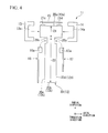
- FIG. 4 is an exploded view showing a configuration of the seal segment 11 according to the embodiment of the present invention. As shown in FIG. 3 , each of the seal segments 11 is inserted into a housing (corresponding to the stationary blade 6 and the bearing parts 2c and 4c) 9.
- the seal segment 11 is constituted by a stacked body 12 in which a plurality of thin plate pieces 20 are stacked (see FIGS. 2 , 8 and 12 ), U-shaped retainers 13 and 14 when seen in a cross-sectional view, a rear surface spacer 15, a high pressure side side sealing plate 16, and a low pressure side side sealing plate 17.
- the plurality of thin plate pieces 20 are stacked (see FIG. 2 ), and base end (one end of the thin plate piece 20 outside in a radial direction of the rotation shaft 5) 20a sides of the plurality of thin plate pieces 20 are mutually connected.
- the thin plate piece 20 is a member formed of a thin steel plate.
- the thin plate piece 20 has substantially a T shape when seen in a tangential direction of the rotation shaft 5, and a width direction thereof coincides with an axial direction of the rotation shaft 5. As shown in FIG.
- the thin plate piece 20 includes a head portion 21 of the base end 20a side, and a body portion 22 of a tip (the other end of the thin plate piece 20 outside in the radial direction of the rotation shaft 5) 20b side.
- the body portion 22 has a width dimension and a thickness dimension smaller than that of the head portion 21.
- Notch portions 20x and 20y are formed in the body portion 22 adjacent to a boundary with the head portion 21.
- the above-mentioned thin plate piece 20 is bended at the boundary between the head portion 21 and the body portion 22 such that an angle formed by the body portion 22 and the head portion 21 is an obtuse angle. That is, the body portion 22 extends from the head portion 21 in an inclined direction.
- the thin plate pieces 20 are mutually connected by welding the lateral protrusion portions 21c and 21d of the head portions 21.
- the body portion 22 of each of the thin plate pieces 20 can be elastically deformed such that the tip 20b of each of the thin plate pieces 20 has a free end.
- the thickness of the head portion 21 is larger than that of the body portion 22. For this reason, a micro gap s (see FIGS. 8 and 12 ) is formed at a position of the body portion 22 between two of the thin plate pieces 20 adjacent to each other in a state in which the thin plate pieces 20 are stacked.
- the stacked body 12 When the plurality of thin plate pieces 20 are stacked, two lateral end surfaces 12c and 12d of the stacked body 12 are formed by each end portion 20c and 20d in a width direction of the body portion 22 of each of the thin plate pieces 20.
- the lateral end surface 12c at which the plurality of lateral end portions 20c of the body portions 22 of the thin plate pieces 20 are gathered is directed toward a high pressure side
- the lateral end surface 12d at which the plurality of lateral end portions 20d of the body portions 22 of the thin plate pieces 20 are gathered is directed toward a low pressure side.
- the stacked body 12 is inserted into the housing 9.
- the tip 20b of each of the thin plate pieces 20 is in contact with the rotation shaft 5 with predetermined pre-compression.
- the high pressure side side sealing plate 16 is a fan-shaped plate member when seen in the axial direction of the rotation shaft 5. As shown in FIG. 3 , the high pressure side side sealing plate 16 covers a portion of the lateral end surface 12c of the stacked body 12 at the high pressure side in the axial direction of the rotation shaft 5. As shown in FIGS. 3 and 4 , a step portion 16a having a large thickness (in the axial direction of the rotation shaft 5) is formed at a base end of the high pressure side side sealing plate 16. The step portion 16a is interposed between the stacked body 12 and the retainer 13 in a state in which the step portion 16a is fitted to the notch portion 20x of the thin plate piece 20.
- the low pressure side side sealing plate 17 is a fan-shaped plate member when seen in the axial direction of the rotation shaft 5. As shown in FIG. 3 , the low pressure side side sealing plate 17 covers a portion of the lateral end surface 12d of the stacked body 12 at the low pressure side in the axial direction of the rotation shaft 5. A step portion 17a having a large thickness (in the axial direction of the rotation shaft 5) is formed at the base end of the low pressure side side sealing plate 17. The step portion 17a is interposed between the stacked body 12 and the retainer 14 in a state in which the step portion 17a is fitted to the notch portion 20y of the thin plate piece 20.
- the low pressure side side sealing plate 17 is shorter than the high pressure side side sealing plate 16 in the radial direction of the rotation shaft. Accordingly, as will be described below, a predetermined gas pressure distribution is formed at the micro gap s.
- the retainers 13 and 14 are arc-shaped members extending in the circumferential direction of the rotation shaft 5.
- the retainers 13 and 14 have a U-shaped cross-sectional shape when seen in a tangential direction of the rotation shaft 5.
- the retainer 13 has a groove 13a formed at a surface thereof opposite to lateral protrusion portions 21c of the head portions 21 of the plurality of thin plate pieces 20.
- the retainer 14 has a groove 14a formed at a surface thereof facing lateral protrusion portions 21d of the head portions 21 of the plurality of thin plate pieces 20.
- the retainers 13 and 14 hold the stacked body 12 by the groove 13a of the retainer 13 and the groove 14a of the retainer 14.
- the rear surface spacer 15 is interposed between the base end 20a of the thin plate piece 20 and portions of the grooves 13a and 14a of the retainers 13 and 14.
- the retainers 13 and 14 hold the lateral protrusion portions 21c and 21d of the head portions 21 of the plurality of thin plate pieces 20 and the rear surface spacer 15 by the groove 13a of the retainer 13 and the groove 14a of the retainer 14.
- the seal segment 11 has a T-shaped cross-section in the tangential direction of the rotation shaft 5.
- the seal segment 11 is accommodated in an annular groove 9a having a T-shaped cross-section in the tangential direction of the rotation shaft 5 formed at the housing 9.
- the retainers 13 and 14 and the head portions 21 of the thin plate pieces 20 are accommodated in an area having a large groove width (in the axial direction of the rotation shaft 5) at an outer circumference side in the radial direction of the annular groove 9a, and the high pressure side side sealing plate 16 and the low pressure side side sealing plate 17 and the body portions 22 of the thin plate pieces 20 are accommodated in an area having a small groove axis at an inner circumference in the radial direction.
- the tip 20b of the body portion 22 projects from an opening of the annular groove 9a toward the rotation shaft 5.
- FIG. 5 is a plan view of a fabricating jig 30 used for fabrication of the seal segment 11 having the configuration
- FIG. 6 is a side view of the fabricating jig 30.
- the fabricating jig 30 includes a jig main body 31 and a tip abutting portion 35 detachable from the jig main body 31.
- the jig main body 31 has a block member having a substantially L-shaped cross-section.
- the jig main body 31 includes an abutting flat surface portion 33 and a base end abutting portion 32 having a larger thickness (a distance from the bottom surface 31a to an upper surface of the base end abutting portion 32) than a thickness dimension (a distance from a bottom surface 31a to an upper surface of the abutting flat surface portion 33) of the abutting flat surface portion 33.
- a groove portion (a head fitting portion) 33a having a smaller thickness (a distance from the bottom surface 31a to the upper surface of the abutting flat surface portion 33) than the other portion of the abutting flat surface portion 33 is formed.
- the groove portion 33a has a groove cross-section of a substantially rectangular shape.
- the groove portion 33a and the lateral protrusion portions 21c and 21d (see FIG. 4 ) of the head portion 21 of the thin plate piece 20 are formed to enable fitting.
- an abutting flat surface 33b of the abutting flat surface portion 33 abuts the lateral end portion 20c of the thin plate piece 20 in a state in which the lateral protrusion portion 21c of the head portion 21 of the thin plate piece 20 is fitted to the groove portion 33a.
- the abutting flat surface 33b of the abutting flat surface portion 33 abuts the lateral end portion 20d of the thin plate piece 20 in a state in which the lateral protrusion portion 21d of the head portion 21 of the thin plate piece 20 is fitted to the groove portion 33a.
- the base end abutting portion 32 has a base end abutting surface 32a continuously formed at the groove portion 33a in a normal direction of the abutting flat surface portion 33.
- the base end 20a of the thin plate piece 20 abuts the base end abutting surface 32a.
- a length of the tip abutting portion 35 is substantially equal to that of the jig main body 31.
- the tip abutting portion 35 is mounted on the jig main body 31.
- the tip abutting surface 35a of the tip abutting portion 35 abuts the tip 20b of the thin plate piece 20 in a state in which any one of the lateral protrusion portions 21c and 21d of the thin plate piece 20 is fitted to the groove portion 33a of the jig main body 31.
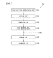
- FIG. 7 is a flowchart illustrating a method F1 of fabricating a seal segment
- FIG. 8 shows a schematic view showing fabricating steps of the method F1 of fabricating the seal segment.
- the seal segment 11 is constituted by the stacked body 12, the retainers 13 and 14, the rear surface spacer 15, the high pressure side side sealing plate 16, and the low pressure side side sealing plate 17.
- a plurality of thin plate pieces 20 formed of a metal plate, which is a base material, are manufactured by a press, etc. (a thin plate piece manufacturing step S11)
- the head portion 21 has a two-ply configuration by folding back the head portion 21 such that the micro gap s is formed between the body portions 22 when the thin plate pieces 20 are straightly stacked. Accordingly, the thickness of the head portion 21 is larger than that of the body portion 22.
- the plurality of thin plate pieces 20 are straightly arranged and stacked (a stacking step S12). Specifically, as shown in FIG. 8 , the lateral protrusion portion 21c of the head portion 21 of each of the thin plate pieces 20 is fitted to the groove portion 33a of the jig main body 31, and the lateral end portion 20c of the thin plate piece 20 abuts the abutting flat surface 33b of the jig main body 31.
- the lateral protrusion portion 21c of the head portion 21 is easily fitted to the groove portion 33a of the jig main body 31.
- a posture of the thin plate piece 20 is easily stabilized, and the lateral end portion 20c easily abuts the abutting flat surface 33b.
- the thin plate pieces 20 are stacked in a width direction of the jig main body 31 such that the body portions 22 of the thin plate pieces 20 extend in the same direction.
- the micro gap s is formed between the body portions 22 of the two adjacent thin plate pieces 20.
- a portion of the thin plate piece 20 may slightly protrude upward by stack distortion or manufacturing error of the thin plate piece 20.
- the base ends 20a of the plurality of thin plate pieces are mutually connected to form a stacked body 12' (a connecting step S13).
- the lateral protrusion portions 21d of the head portions 21 of the stacked thin plate pieces 20 are welded to form a linear junction J, mutually connecting the thin plate pieces 20.
- the stacked body 12' in which the plurality of thin plate pieces 20 are straightly connected is formed. Even in this case, some of the thin plate pieces 20 may slightly protrude upward to generate convex portions from the lateral end surface 12d due to distortion of the welding.
- the tip abutting portion 35 is mounted on the jig main body 31 (see FIG. 6 ), and the tip abutting surface 35a abuts the tip 20b of the thin plate piece 20, supporting the tip 20b.
- the lateral end surface 12c of the stacked body 12 abuts a flat surface, and the other lateral end surface 12d is ground (smoothed) (a first grinding step (a first smoothing step) S14).
- a first grinding step a first smoothing step S14.
- a base end surface 12a of the stacked body 12 abuts the base end abutting surface 32a, and a tip surface 12b of the stacked body 12 abuts the tip abutting surface 35a, so that both ends thereof are supported.
- each of the thin plate pieces 20 cannot be easily flexed so that the thin plate pieces 20 cannot be easily tensed or bounced by rotation of the hand grinder G, or the like.
- the lateral end surface 12d may be smoothed by another machining method (for example, electrical discharge machining).
- the stacked body 12' is bended to a predetermined curvature (a bending step S15).
- the integrally connected head portions 21 are plastically deformed to a predetermined curvature such that the body portion 22 side is recessed, forming the stacked body 12.
- the stacked body 12, the retainers 13 and 14, the rear surface spacer 15, the high pressure side side sealing plate 16, and the low pressure side side sealing plate 17 are assembled to complete the seal segment 11 (assembling step S16).
- the step portion 16a of the high pressure side side sealing plate 16 and the step portion 17a of the low pressure side side sealing plate 17 are fitted to the notch portions 20x and 20y of the stacked body 12, respectively, and the head portion 21 of the stacked body 12 is fitted to the groove 13a of the retainer 13 and the groove 14a of the retainer 14 via the rear surface spacer 15.
- the seal segments 11 are completed.
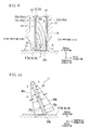
- FIG. 9 is a gas pressure distribution view of a working fluid g formed at the micro gap s
- FIG. 10 is a view showing a cross-sectional view of the body portion 22 crossing in the axial direction of the rotation shaft 5 and pressures applied to the body portion 22 as vectors.
- a surface facing the rotation shaft 5 of the thin plate piece 20 is referred to as a lower surface 20q
- a rear surface thereof is referred to as an upper surface 20p.
- a high pressure side region and a low pressure side region of the working fluid g are generated with reference to the shaft sealing mechanism 10 as a boundary.
- the seal segments 11 receive a pressure from the high pressure side region toward the low pressure side region, and the low pressure side side sealing plate 17 is adhered to the housing 9.
- the working fluid g flows between an outer circumference surface of the rotation shaft 5 and the tip 20b of the thin plate piece 20, and flows through each of the micro gaps s. That is, the working fluid g introduced into the micro gap s radially flows from a corner r1 toward a corner r2 along the upper surface 20p and the lower surface 20q opposite to each other with the micro gap s interposed therebetween.
- a gas pressure distribution 40a in which a gas pressure is the highest at the corner r1 disposed at the tip 20b of the thin plate piece 20 and the high pressure side, and a gas pressure is gradually reduced toward the corner r2 diagonal thereto is formed.
- gas pressure distribution 40a As shown in FIG. 9 , in the gas pressure distribution 40a, a low pressure region is enlarged toward the base end 20a of the thin plate piece 20. For this reason, as shown in FIG. 10 , gas pressure distributions 40b and 40c applied to the upper surface 20p and the lower surface 20q of each of the thin plate pieces 20 become triangular distribution shapes in which the gas pressure is increased as they approach the tip 20b of the thin plate piece 20 and is reduced as they approach the base end 20a.
- the lateral end surface 12d of the stacked body 12 is smoothed, and a downstream side space L of a discharge part through which the working fluid g is discharged from the micro gap s has the same size at each position in the circumferential direction. That is, in the seal segment 11, as some of the thin plate pieces 20 protruding from the lateral end surface 12d are ground and smoothed like the normally stacked thin plate pieces 20, the downstream side space L has the same size at each position in the circumferential direction.
- the seal segment 11 since the seal segment 11 receives the pressure from the working fluid to be adhered to the housing 9, in order to approach the designed gas pressure distribution, it is needed to precisely secure the size of the downstream side space L of a fluid outlet part more than an upstream side space H of a fluid inlet part of each of the micro gaps s. As described above, each of the micro gaps s in the seal segments 11 secures the downstream side space L of the fluid outlet part to have the same normal size, and the actual gas pressure distribution 40a approximates to the designed gas pressure distribution.
- a lifting force F L is generated in a direction lifting from the rotation shaft 5 with respect to the tip 20b of the thin plate piece 20.
- the actual gas pressure distribution 40a in each of the micro gaps s is substantially equal to the designed gas pressure distribution, the lifting force F L is also substantially equal to the designed lifting force.
- seal clearance as designed is formed between the thin plate piece 20 and the rotation shaft 5.
- the method F1 of fabricating the seal segment according to the embodiment includes a first grinding step S14 of bringing the lateral end surface 12c directed toward the low pressure side of the working fluid g in contact with the abutting flat surface 33b of the fabricating jig 30 and grinding the lateral end surface 12d directed toward the high pressure side of the working fluid g.
- the method F1 of fabricating the seal segment of the embodiment even when the lateral end surface 12d is uneven due to manufacturing error or stack distortion of the thin plate piece 20 or distortion of the welding, or the like, the lateral end surface 12d is smoothed.
- the downstream side space L of the micro gap s formed between the body portions 22 of the adjacent thin plate pieces 20 has an uniform size throughout in the circumferential direction.
- the gas pressure distribution in each of the micro gaps s is substantially equal throughout in the circumferential direction. Accordingly, it is possible to suppress a local decrease in lifting characteristics of the thin plate piece 20. As a result, it is possible to suppress a decrease in seal performance and contact wearing between the thin plate piece 20 and the rotation shaft 5.
- the downstream side space L can be easily configured to have a designed size throughout in the circumferential direction. For this reason, the actual gas pressure distribution in each of the micro gaps s can be easily approximately be to the designed gas pressure distribution.
- the method F1 of fabricating the seal segment according to the embodiment includes a bending step S15 of bending the stacked body 12 after the first grinding step S14. For this reason, when the grinding is performed on the straightly connected stacked body 12, the first grinding step S14 can be relatively easily performed.
- the grinding is performed with the tip surface 12b in which the tips 20b of the plurality of thin plate pieces 20 are gathered while being supported. For this reason, it is possible to suppress the tip 20b side of the thin plate piece 20 from being bended by the grinding. As a result, the grinding can be relatively easily and precisely performed.
- the fabricating jig 30 of the seal segments 11 includes the groove portion 33a to which the lateral protrusion portions 21d of the plurality of thin plate pieces 20 are fitted, and the abutting flat surface portion 33 configured to abut the lateral end portions 20c of the plurality of thin plate pieces 20.
- the thin plate piece 20 can be rapidly and precisely positioned, and the stacking step S12 can be easily performed.
- the grinding on the lateral end surface 12d of the stacked body 12 can be rapidly and precisely performed, and the first grinding step S14 can be easily performed.
- the fabricating jig 30 of the seal segment 11 includes the tip abutting portion 35 abutting the tips 20b of the plurality of thin plate pieces 20.
- the thin plate piece 20 can be more rapidly and precisely positioned, and the stacking step S12 can be more easily performed.
- the grinding on the stacked body 12 can be more rapidly and precisely performed, and the first grinding step S14 can be more easily performed.
- the gas turbine 1 according to the embodiment includes the seal segments 11, the sealing in the axial direction is performed in the state in which the seal performance with respect to the working fluid g is maintained and continuously. Therefore, the maintenance characteristics are improved.
- FIG. 11 is a flowchart of a method F2 of fabricating a seal segment as a variant of the method F1 of fabricating the seal segment
- FIG. 12 is a plan view of a fabricating jig 50 used therein.
- like elements of the above-mentioned embodiment are designated by like reference numerals, and description thereof will not be repeated.
- the method F2 of fabricating the seal segment is similar to the method F1 of fabricating the seal segment in the thin plate piece manufacturing step S11 to the connecting step S13 of the thin plate piece 20.
- the method F2 of fabricating the seal segment unlike the method F1 of fabricating the seal segment, after the connecting step S13 of the thin plate piece 20, the method F2 includes a bending step S24 with respect to the stacked body 12', and a first grinding step (first smoothing step) S25 (see FIG. 7 ).
- the fabricating jig 30 can be used until the connecting step S13 of the thin plate piece 20.
- the fabricating jig 50 having a curved shape is used to grind the lateral end surface 12d.
- a side view of the fabricating jig 50 is similar to the side view of the fabricating jig 30 of FIG. 6 .
- the stacked body 12' is bended after the connecting step S13 and before the first grinding step S25, even when unevenness is generated on the lateral end surface 12d by the bending step S24, the lateral end surface 12d can be smoothed in the first grinding step S25.
- the method F2 of fabricating the seal segment may include, after the bending step S24, a pre-assembling step (a retainer mounting step) S26 of assembling the retainers 13 and 14 and the rear surface spacer 15 to the stacked body 12. That is, as shown in FIG. 13 , as the head portion 21 of each of the thin plate pieces 20 of the stacked body 12 is fixed and held by the retainers 13 and 14, flexing of the base end 20a side of the thin plate piece 20 can be effectively suppressed. As a result, the grinding can be relatively easily and precisely performed. Further, in this case, the groove portion 33a of the fabricating jig 50 may be configured to be fitted to the retainers 13 and 14. In this case, in the assembling step S16, the high pressure side side sealing plate 16 and the low pressure side side sealing plate 17 may be inserted in the circumferential direction from one ends thereof to assemble the seal segment 11.
- the fabricating method may include a second grinding step (a second smoothing step) of grinding the lateral end surface 12c (see S30 of FIGS. 7 and 11 ).
- a second grinding step a second smoothing step of grinding the lateral end surface 12c (see S30 of FIGS. 7 and 11 ).
- a size of the upstream side space H of the fluid introduction part of the micro gap s is uniformized throughout in the circumferential direction. Accordingly, a gas pressure distribution in each of the micro gaps s can be further uniformized, and local variation in lifting characteristics can be further suppressed.
- the lateral end surface 12c may be smoothed using another machining method (electrical discharge machining).
- the lateral end surface 12d may be directed toward the low pressure side region.
- the lateral end surface 12d may be ground to be smoothed such that a distance between the abutting flat surface 33b and the lateral end surface 12d is constant.
- machining allowance is provided to a width dimension of (the body portion 22 of) the thin plate piece 20 in the thin plate piece manufacturing step S11, excessive grinding of the thin plate piece 20 can be prevented.
- first grinding steps S14 and S25 have a configuration in which the hand grinder G is used, another grinding tool and machine tool may be used.
- the thin plate piece manufacturing step S11 while the thin plate piece 20 is manufactured by a press, the thin plate piece may be manufactured using another method such as etching, or the like.
- etching or the like.
- a stacked body 12 in which the thin plate pieces 20 inclined between the head portion 21 and the body portion 22 are stacked is used, a stacked body in which thin plate pieces straightly formed (not inclined) between the head portion 21 and the body portion 22 are stacked may be applied to the present invention.
- seal segments 11 in accordance with the present invention are applied to the gas turbine 1
- the seal segments can be widely applied to rotary machines such as a steam turbine, a compressor, a water wheel, a freezing machine, a pump, and so on.
- the method of fabricating a shaft sealing device in accordance with the present invention it is possible to obtain a shaft sealing device capable of suppressing a decrease in seal performance and suppressing contact wearing between the thin plate piece and the rotation shaft.
- the jig for fabricating the shaft sealing device in accordance with the present invention it is possible to easily perform the method of fabricating a shaft sealing device.
- the rotary machine in accordance with the present invention maintenance characteristics can be improved.
Landscapes
- Engineering & Computer Science (AREA)
- General Engineering & Computer Science (AREA)
- Mechanical Engineering (AREA)
- Chemical & Material Sciences (AREA)
- Combustion & Propulsion (AREA)
- Turbine Rotor Nozzle Sealing (AREA)
- Sealing Devices (AREA)
Abstract
Description
- The present invention relates to a method of fabricating a shaft sealing device, a jig for fabricating the shaft sealing device, and a rotary machine provided with the shaft sealing device.
This application claims priority to and the benefit of Japanese Patent Application No.2010-108691, filed May 10, 2010 - As is well known, in a rotary machine such as a gas turbine, a steam turbine, a compressor, a water wheel, a freezing machine, a pump, or the like, a device disclosed in the following Patent Document 1 is provided as a shaft sealing mechanism configured to seal a rotation shaft.
-
FIG. 14 is a schematic perspective view showing a configuration of a shaft sealing mechanism100 in the related art.
Theshaft sealing mechanism 100 includes ashaft sealing device 102 accommodated in ahousing 101 that encloses a rotation shaft R at a stator side of rotary machine. - The
shaft sealing device 102 includes a stackedbody 103, a high pressure sideside sealing plate 104, and a low pressure sideside sealing plate 105. Thestacked body 103 has a plurality ofthin plate pieces 103a stacked along a periphery of the rotation shaft R in a circumferential direction. The high pressure sideside sealing plate 104 covers a portion of thestacked body 103 at a high pressure side of the fluid. The low pressure sideside sealing plate 105 covers a portion of thestacked body 103 at a low pressure side of the fluid. In thestacked body 103, base end sides of the plurality ofthin plate pieces 103a are mutually connected, and tips are free ends. The base end sides of thethin plate pieces 103a are accommodated in thehousing 101. Each of thethin plate pieces 103a extends from thehousing 101 toward the rotation shaft R to be inclined from a radial direction of the rotation shaft to a tangential direction. - In the
shaft sealing mechanism 100 having such a configuration, while the tips of thethin plate pieces 103a contact the rotation shaft R with predetermined pre-compression when the rotation shaft R is stopped, a lifting force is applied to thethin plate pieces 103a by a dynamic pressure effect when the rotation shaft R is rotated. As the lifting force is used, a micro gap is formed by thethin plate piece 103a and the rotation shaft R to seal a working fluid, and wear between the rotation shaft R and each of thethin plate pieces 103a is prevented. -
- [Patent Document 1] Japanese Patent No.
3917993 - Here, in the above-mentioned shaft sealing mechanism, a gas pressure distribution in the micro gap formed between two adjacent thin plate pieces is set to adjust inner diameter dimensions of the high pressure side side sealing plate and the low pressure side side sealing plate. That is, as dimensions of an upstream side space of a fluid introduction part of the micro gap and a downstream side space of a fluid discharge part are adjusted, the gas pressure distribution in the micro gap is set. For example, when the low pressure side side sealing plate is shorter than the high pressure side side sealing plate, the gas pressure distribution in the micro gap is gradually reduced from the tip toward the base end. As a result, the pressure can be applied to the thin plate pieces such that the dynamic pressure effect assists the lifting force.
- In the stacked body of the shaft sealing mechanism, normally, after the thin plate pieces are stacked in one direction, base ends of the thin plate pieces are connected by welding or the like, and then a process of bending the thin plate pieces at a predetermined curvature is applied and the shaft sealing device is assembled.
- However, in the related art, due to stack distortion generated from some of the thin plate pieces and manufacturing error of each of the thin plate pieces in a process of fabricating the stacked body, local variation in size occurs at an area in the upstream side space or the downstream side space. For this reason, the gas pressure distribution in the micro gap near the area is different from the gas pressure distribution in the micro gap of the other area. Accordingly, lifting characteristics of the thin plate pieces are locally varied, the thin plate pieces and the rotation shaft are worn by contacts therebetween, and sealing performance is decreased.
- In consideration of the above-mentioned circumstances, it is an object of the present invention to provide a method of fabricating a shaft sealing device, a jig for fabricating the shaft sealing device, and a rotary machine provided with the shaft sealing device that are capable of suppressing a decrease in seal performance, and suppressing contact wearing between a thin plate piece and a rotation shaft.
- In order to accomplish the object, the present invention provides the following means.
The present invention provides a method of fabricating a shaft sealing device with a plurality of thin plate pieces arranged in a circumferential direction of a rotation shaft, base ends of the thin plate pieces being mutually connected, the method comprising the steps of: stacking in which the plurality of thin plate pieces are stacked in one direction; connecting in which the base ends of the plurality of the stacked thin plate pieces are mutually connected to form a stacked body; and first smoothing in which an one lateral end surface, which is one of two lateral end surfaces of the stacked body formed on each end portion in a width direction of the plurality of thin plate pieces, is abutted to a flat surface, and the other lateral end surface is smoothed. - According to the above-mentioned configuration, since one lateral end surface of the two lateral end surfaces of the stacked body abuts the flat surface and the other lateral end surface is smoothed, unevenness of the other lateral end surface due to stack distortion or manufacturing error of the thin plate piece can be smoothed. Accordingly, in at least one of an upstream side space of a fluid introduction part of a micro gap formed between the adjacent thin plate pieces and a downstream side space of the fluid discharge part, the space has a uniform size throughout in the circumferential direction. Accordingly, a gas pressure distribution in each micro gap is uniformized. As a result, a local difference in lifting characteristics of the thin plate piece can be suppressed. Accordingly, a decrease in seal performance can be suppressed, and contact wearing between the thin plate piece and the rotation shaft can be suppressed.
- In the step of first smoothing, the smoothing may be performed in such a way that a distance between the flat surface and the other lateral end surface is constant.
According to the above-mentioned configuration, since the other lateral end surface is smoothed, the size of at least one of the upstream side space of the fluid introduction part of the micro gap and the downstream side space of the fluid discharge part is further uniformized throughout in the circumferential direction. Accordingly, the gas pressure distribution in each of the micro gaps is further uniformized. As a result, a local difference in lifting characteristics of the thin plate piece can be further suppressed. - The method of fabricating a shaft sealing device of the present invention may further comprise the step of bending in which the stacked body is bended after the step of first smoothing.
According to the above-mentioned configuration, since the method includes the bending step of bending the stacked body after the first smoothing step, the smoothing can be relatively easily performed in comparison with the case in which the bended stacked body is smoothed. - The method of fabricating a shaft sealing device of the present invention may further comprise the step of bending in which the stacked body is bended after the step of connecting, wherein the step of first smoothing is performed to the bended stacked body.
According to the above-mentioned configuration, since the stacked body is bended after the connecting step, even when unevenness occurs from the other lateral end surface by the bending, the other lateral end surface can be smoothed. - The method of fabricating a shaft sealing device of the present invention may further comprise the step of mounting a retainer, in which the retainer that can be fitted to at least a portion of the stacked body at a side of the base end of the thin plate pieces is mounted to the portion of the stacked body after the step of connecting, wherein the step of first smoothing is performed in a state where the retainer is fitted to the stacked body.
According to the above-mentioned configuration, since the smoothing is performed in the first smoothing step in the state in which the retainer is fitted to the stacked body, the base end side of the thin plate piece is held by the retainer so that the smoothing can be relatively easily performed. - In the step of first smoothing, a tip surface of the stacked body formed by tips of the plurality of thin plate pieces is supported.
According to the above-mentioned configuration, since the smoothing is performed in a state in which the tip surface of the stacked body is supported, the tip of the thin plate piece cannot be easily flexed by the smoothing, and the smoothing can be relatively easily and precisely performed. - The method of fabricating a shaft sealing device of the present invention comprises the step of second smoothing in which the one lateral end surface which is abutted to the flat surface in the step of first smoothing is smoothed.
According to the above-mentioned configuration, since the method includes the second smoothing step of smoothing the one lateral end surface, the one lateral end surface is smoothed. Accordingly, since both of the lateral end surfaces of the stacked body are smoothed, the sizes of both of the upstream side space of the fluid introduction part of the micro gap and the downstream side space of the fluid discharge part are uniformized. Therefore, the gas pressure distribution in each of the micro gaps is further uniformized, and local variation in lifting characteristics can be further suppressed. As a result, a decrease in seal performance can be more reliably suppressed, and contact wearing between the thin plate piece and the rotation shaft can be more reliably suppressed. - A jig for fabricating a shaft sealing device of the present invention comprises: a head fitting portion that fits to head portions of the base end sides of the plurality of thin plate pieces; and an abutting flat surface abutting to the one lateral end surface of the two lateral end surfaces of the stacked body formed by each end portion in the width direction of the plurality of thin plate pieces in a state where the head portions of the thin plate pieces are fitted to the head fitting portion.
In addition, a jig for fabricating a shaft sealing device of the present invention comprises: a retainer fitting portion that fits to the retainer fitted to the stacked body; and an abutting flat surface abutting to the one lateral end surface of the two lateral end surfaces of the stacked body formed by each end portion in the width direction of the plurality of thin plate pieces in a state where the retainer is fitted to the retainer fitting portion.
According to these configurations, since the jig includes the fitting portion fitted to the base end of the thin plate piece or the retainer fitting portion fitted to the retainer, and the abutting flat surface abutting the one lateral end surface of the two lateral end surfaces of the stacked body, the thin plate piece can be rapidly and precisely positioned, and the smoothing with respect to the stacked body can be rapidly and precisely performed. - The jig may further comprise a tip abutting portion abutting to a tip surface of the stacked body formed by tips of the plurality of thin plate pieces.
According to the above-mentioned configuration, since the jig includes the tip abutting portion abutting the tips of the plurality of thin plate pieces, the thin plate piece can be more rapidly and precisely positioned. For this reason, the stacking step can be more easily performed, and the smoothing with respect to the stacked body can be more rapidly and precisely performed. Accordingly, the first smoothing step can be more easily performed. - A rotary machine in accordance with the present invention comprises the shaft sealing device, which is fabricated by any one of the above-mentioned methods of fabricating the shaft sealing device and disposed at a periphery of the rotation shaft.
According to the above-mentioned configuration, since the rotary machine includes the shaft sealing device, which is fabricated according to any one of the above-mentioned methods of fabricating the shaft sealing device, in a state in which seal performance with respect to the working fluid is maintained, sealing in the axial direction can be continuously maintained. Accordingly, it is possible to obtain the rotary machine having good maintenance characteristics. - According to a method of fabricating a shaft sealing device of the present invention, it is possible to provide a shaft sealing device capable of suppressing a decrease in seal performance and suppressing contact wearing between a thin plate piece and a rotation shaft.
- According to a jig for fabricating a shaft sealing device of the present invention, the method of fabricating a shaft sealing device can be easily performed.
- According to a rotary machine of the present invention, maintenance characteristics can be improved.
-
-
FIG. 1 is a schematic view showing the entire configuration of a gas turbine 1 according to an embodiment of the present invention. -
FIG. 2 is a cross-sectional view taken along line I-I ofFIG. 1 . -
FIG. 3 is a schematic cross-sectional view of a configuration of ashaft sealing mechanism 10 according to the embodiment of the present invention, showing a cross-section along an axis of arotation shaft 5. -
FIG. 4 is an exploded view showing a configuration of aseal segment 11 according to the embodiment of the present invention. -
FIG. 5 is a plan view of a fabricatingjig 30 used for fabrication of theseal segment 11 according to the embodiment of the present invention. -
FIG. 6 is a side view of the fabricatingjig 30 used for fabrication of theseal segment 11 according to the embodiment of the present invention. -
FIG. 7 is a flowchart showing a method F1 of fabricating a seal segment according to an embodiment of the present invention. -
FIG. 8 is a schematic view of a fabricating step of the method F1 of fabricating the seal segment according to the embodiment of the present invention. -
FIG. 9 is a gas pressure distribution view of a working fluid g formed at a micro gap s of theseal segment 11 according to the embodiment of the present invention. -
FIG. 10 is a cross-sectional view showing a major part of abody portion 22 of athin plate piece 20 in theseal segment 11 according to the embodiment of the present invention, showing a cross-section of thebody portion 22 crossing therotation shaft 5 in an axial direction and showing a pressure applied to thebody portion 22 as a vector. -
FIG. 11 is a flowchart showing a method F2 of fabricating a seal segment, which is a variant of the method F1 of fabricating a seal segment according to the embodiment of the present invention. -
FIG. 12 is a view showing a fabricatingjig 50 used for the method F2 of fabricating the seal segment according to the embodiment of the present invention. -
FIG. 13 is a side view of the fabricatingjig 50 used for fabrication of theseal segment 11 according to the embodiment of the present invention. -
FIG. 14 is a schematic perspective view showing a configuration of ashaft sealing mechanism 100 in the related art. - Hereinafter, embodiments of the present invention will be described with reference to the accompanying drawings.
-
FIG. 1 is a schematic view showing the entire configuration of a gas turbine (a rotary machine) 1 according to an embodiment of the present invention, andFIG. 2 is a cross-sectional view taken along line I-I ofFIG. 1 .
As shown inFIG. 1 , the gas turbine 1 includes a compressor (a rotary machine) 2 configured to introduce a large amount of air thereinto and compress the air, acombustor 3 configured to mix fuel with the air compressed by thecompressor 2 to combust the mixture, and a turbine (a rotary machine) 4 configured to convert thermal energy of a combustion gas introduced from thecombustor 3 into rotational energy. Arotation shaft 5 of the gas turbine 1 is configured by arotor 2a of thecompressor 2, arotor 4a of the turbine 4 and arotation shaft 5a, which are coaxially connected to each other. - As shown in
FIG. 1 , a plurality ofstationary blades 6 are installed at inner circumferences of acompressor casing 2b of thecompressor 2 and aturbine casing 4b of the turbine 4 in a circumferential direction in an annular shape at predetermined intervals. In addition, a plurality of moving blades 7 are installed at outer circumferences of therotor 2a of thecompressor 2 and therotor 4a of the turbine 4 in a circumferential direction in an annular shape at predetermined intervals. Thestationary blades 6 and the moving blades 7 are alternately arranged in an axial direction of therotation shaft 5. - In the gas turbine 1, in order to prevent leakage of a working fluid (compressed air or a combustion gas) g from a high pressure side to a low pressure side of the
stationary blade 6 in an axial direction,shaft sealing mechanisms 10 are disposed at inner circumferences of thestationary blades 6.
In addition, theshaft sealing mechanisms 10 are also disposed at abearing part 2c in which thecompressor casing 2b supports therotation shaft 5a, and abearing part 4c in which theturbine casing 4b supports therotation shaft 5a. - As shown in
FIG. 2 , each of theshaft sealing mechanisms 10 is configured by disposing a plurality of (eight, in the embodiment) arc-shaped seal segments (a shaft sealing device) 11 in the circumferential direction of therotation shaft 5 in an annular shape. -
FIG. 3 is a schematic cross-sectional view of a configuration of theshaft sealing mechanism 10, showing a cross-section along an axis of therotation shaft 5, andFIG. 4 is an exploded view showing a configuration of theseal segment 11 according to the embodiment of the present invention. As shown inFIG. 3 , each of theseal segments 11 is inserted into a housing (corresponding to thestationary blade 6 and the bearingparts - As shown in
FIG. 3 , theseal segment 11 is constituted by astacked body 12 in which a plurality ofthin plate pieces 20 are stacked (seeFIGS. 2 ,8 and12 ),U-shaped retainers rear surface spacer 15, a high pressure sideside sealing plate 16, and a low pressure sideside sealing plate 17. - In the
stacked body 12, the plurality ofthin plate pieces 20 are stacked (seeFIG. 2 ), and base end (one end of thethin plate piece 20 outside in a radial direction of the rotation shaft 5) 20a sides of the plurality ofthin plate pieces 20 are mutually connected.
As shown inFIG. 3 , thethin plate piece 20 is a member formed of a thin steel plate. Thethin plate piece 20 has substantially a T shape when seen in a tangential direction of therotation shaft 5, and a width direction thereof coincides with an axial direction of therotation shaft 5. As shown inFIG. 4 , thethin plate piece 20 includes ahead portion 21 of thebase end 20a side, and abody portion 22 of a tip (the other end of thethin plate piece 20 outside in the radial direction of the rotation shaft 5) 20b side. Thebody portion 22 has a width dimension and a thickness dimension smaller than that of thehead portion 21.Notch portions body portion 22 adjacent to a boundary with thehead portion 21.
As shown inFIG. 5 , the above-mentionedthin plate piece 20 is bended at the boundary between thehead portion 21 and thebody portion 22 such that an angle formed by thebody portion 22 and thehead portion 21 is an obtuse angle. That is, thebody portion 22 extends from thehead portion 21 in an inclined direction. - The
thin plate pieces 20 are mutually connected by welding thelateral protrusion portions head portions 21. Thebody portion 22 of each of thethin plate pieces 20 can be elastically deformed such that thetip 20b of each of thethin plate pieces 20 has a free end.
In thethin plate piece 20, the thickness of thehead portion 21 is larger than that of thebody portion 22. For this reason, a micro gap s (seeFIGS. 8 and12 ) is formed at a position of thebody portion 22 between two of thethin plate pieces 20 adjacent to each other in a state in which thethin plate pieces 20 are stacked. - When the plurality of
thin plate pieces 20 are stacked, two lateral end surfaces 12c and 12d of the stackedbody 12 are formed by eachend portion body portion 22 of each of thethin plate pieces 20.
Here, thelateral end surface 12c at which the plurality oflateral end portions 20c of thebody portions 22 of thethin plate pieces 20 are gathered is directed toward a high pressure side, and thelateral end surface 12d at which the plurality oflateral end portions 20d of thebody portions 22 of thethin plate pieces 20 are gathered is directed toward a low pressure side. In this state, thestacked body 12 is inserted into thehousing 9. In thestacked body 12, when therotation shaft 5 is stopped, thetip 20b of each of thethin plate pieces 20 is in contact with therotation shaft 5 with predetermined pre-compression. - The high pressure side
side sealing plate 16 is a fan-shaped plate member when seen in the axial direction of therotation shaft 5. As shown inFIG. 3 , the high pressure sideside sealing plate 16 covers a portion of thelateral end surface 12c of the stackedbody 12 at the high pressure side in the axial direction of therotation shaft 5. As shown inFIGS. 3 and4 , astep portion 16a having a large thickness (in the axial direction of the rotation shaft 5) is formed at a base end of the high pressure sideside sealing plate 16. Thestep portion 16a is interposed between thestacked body 12 and theretainer 13 in a state in which thestep portion 16a is fitted to thenotch portion 20x of thethin plate piece 20. - The low pressure side
side sealing plate 17 is a fan-shaped plate member when seen in the axial direction of therotation shaft 5. As shown inFIG. 3 , the low pressure sideside sealing plate 17 covers a portion of thelateral end surface 12d of the stackedbody 12 at the low pressure side in the axial direction of therotation shaft 5. Astep portion 17a having a large thickness (in the axial direction of the rotation shaft 5) is formed at the base end of the low pressure sideside sealing plate 17. Thestep portion 17a is interposed between thestacked body 12 and theretainer 14 in a state in which thestep portion 17a is fitted to thenotch portion 20y of thethin plate piece 20. - The low pressure side
side sealing plate 17 is shorter than the high pressure sideside sealing plate 16 in the radial direction of the rotation shaft. Accordingly, as will be described below, a predetermined gas pressure distribution is formed at the micro gap s. - The
retainers rotation shaft 5. Theretainers rotation shaft 5. As shown inFIGS. 3 and4 , theretainer 13 has agroove 13a formed at a surface thereof opposite tolateral protrusion portions 21c of thehead portions 21 of the plurality ofthin plate pieces 20.
As shown inFIGS. 3 and4 , theretainer 14 has agroove 14a formed at a surface thereof facinglateral protrusion portions 21d of thehead portions 21 of the plurality ofthin plate pieces 20. - As shown in
FIG. 3 , in theseal segment 11, theretainers stacked body 12 by thegroove 13a of theretainer 13 and thegroove 14a of theretainer 14.
Therear surface spacer 15 is interposed between thebase end 20a of thethin plate piece 20 and portions of thegrooves retainers
Specifically, theretainers lateral protrusion portions head portions 21 of the plurality ofthin plate pieces 20 and therear surface spacer 15 by thegroove 13a of theretainer 13 and thegroove 14a of theretainer 14. - As shown in
FIG. 3 , theseal segment 11 has a T-shaped cross-section in the tangential direction of therotation shaft 5. Theseal segment 11 is accommodated in anannular groove 9a having a T-shaped cross-section in the tangential direction of therotation shaft 5 formed at thehousing 9. Specifically, theretainers head portions 21 of thethin plate pieces 20 are accommodated in an area having a large groove width (in the axial direction of the rotation shaft 5) at an outer circumference side in the radial direction of theannular groove 9a, and the high pressure sideside sealing plate 16 and the low pressure sideside sealing plate 17 and thebody portions 22 of thethin plate pieces 20 are accommodated in an area having a small groove axis at an inner circumference in the radial direction. Here, thetip 20b of thebody portion 22 projects from an opening of theannular groove 9a toward therotation shaft 5. - Next, a jig used for fabrication of the
seal segment 11 according to the embodiment of the present invention will be described.
FIG. 5 is a plan view of a fabricatingjig 30 used for fabrication of theseal segment 11 having the configuration, andFIG. 6 is a side view of the fabricatingjig 30. - As shown in
FIGS. 5 and 6 , the fabricatingjig 30 includes a jigmain body 31 and atip abutting portion 35 detachable from the jigmain body 31.
As shown inFIG. 6 , the jigmain body 31 has a block member having a substantially L-shaped cross-section. The jigmain body 31 includes an abuttingflat surface portion 33 and a baseend abutting portion 32 having a larger thickness (a distance from thebottom surface 31a to an upper surface of the base end abutting portion 32) than a thickness dimension (a distance from abottom surface 31a to an upper surface of the abutting flat surface portion 33) of the abuttingflat surface portion 33. - As shown in
FIGS. 5 and 6 , at a portion of the abuttingflat surface portion 33 having a predetermined width from a boundary between the abuttingflat surface portion 33 and the baseend abutting portion 32, a groove portion (a head fitting portion) 33a having a smaller thickness (a distance from thebottom surface 31a to the upper surface of the abutting flat surface portion 33) than the other portion of the abuttingflat surface portion 33 is formed. - As shown in
FIG. 6 , thegroove portion 33a has a groove cross-section of a substantially rectangular shape. Thegroove portion 33a and thelateral protrusion portions FIG. 4 ) of thehead portion 21 of thethin plate piece 20 are formed to enable fitting. - As shown in
FIG. 6 , an abuttingflat surface 33b of the abuttingflat surface portion 33 abuts thelateral end portion 20c of thethin plate piece 20 in a state in which thelateral protrusion portion 21c of thehead portion 21 of thethin plate piece 20 is fitted to thegroove portion 33a. In addition, the abuttingflat surface 33b of the abuttingflat surface portion 33 abuts thelateral end portion 20d of thethin plate piece 20 in a state in which thelateral protrusion portion 21d of thehead portion 21 of thethin plate piece 20 is fitted to thegroove portion 33a. - As shown in
FIGS. 5 and 6 , the baseend abutting portion 32 has a baseend abutting surface 32a continuously formed at thegroove portion 33a in a normal direction of the abuttingflat surface portion 33. In the baseend abutting portion 32, in a state in which any one of thelateral protrusion portions thin plate piece 20 is fitted to thegroove portion 33a, thebase end 20a of thethin plate piece 20 abuts the baseend abutting surface 32a. - As shown in
FIG. 5 , a length of thetip abutting portion 35 is substantially equal to that of the jigmain body 31. As shown inFIG. 6 , thetip abutting portion 35 is mounted on the jigmain body 31. Thetip abutting surface 35a of thetip abutting portion 35 abuts thetip 20b of thethin plate piece 20 in a state in which any one of thelateral protrusion portions thin plate piece 20 is fitted to thegroove portion 33a of the jigmain body 31. - Next, a method of fabricating a seal segment (a method of fabricating a shaft sealing device) according to the embodiment of the present invention will be described.
FIG. 7 is a flowchart illustrating a method F1 of fabricating a seal segment, andFIG. 8 shows a schematic view showing fabricating steps of the method F1 of fabricating the seal segment.
As described above, theseal segment 11 is constituted by the stackedbody 12, theretainers rear surface spacer 15, the high pressure sideside sealing plate 16, and the low pressure sideside sealing plate 17. - First, as shown in
FIGS. 7 and8 , a plurality ofthin plate pieces 20 formed of a metal plate, which is a base material, are manufactured by a press, etc. (a thin plate piece manufacturing step S11)
Here, only thehead portion 21 has a two-ply configuration by folding back thehead portion 21 such that the micro gap s is formed between thebody portions 22 when thethin plate pieces 20 are straightly stacked. Accordingly, the thickness of thehead portion 21 is larger than that of thebody portion 22. - Next, as shown in
FIG. 7 , the plurality ofthin plate pieces 20 are straightly arranged and stacked (a stacking step S12).
Specifically, as shown inFIG. 8 , thelateral protrusion portion 21c of thehead portion 21 of each of thethin plate pieces 20 is fitted to thegroove portion 33a of the jigmain body 31, and thelateral end portion 20c of thethin plate piece 20 abuts the abuttingflat surface 33b of the jigmain body 31. - During the stacking step S12, as shown in
FIG. 8 , when the step is performed in a state in which thetip abutting portion 35 is removed from the fabricatingjig 30, thelateral protrusion portion 21c of thehead portion 21 is easily fitted to thegroove portion 33a of the jigmain body 31. In addition, as thelateral protrusion portion 21c of thehead portion 21 of each of thethin plate pieces 20 is fitted to thegroove portion 33a of the jigmain body 31, a posture of thethin plate piece 20 is easily stabilized, and thelateral end portion 20c easily abuts the abuttingflat surface 33b. - As shown in
FIG. 8 , thethin plate pieces 20 are stacked in a width direction of the jigmain body 31 such that thebody portions 22 of thethin plate pieces 20 extend in the same direction. As thethin plate pieces 20 are stacked as described above, the micro gap s is formed between thebody portions 22 of the two adjacentthin plate pieces 20.
Here, as indicated by dotted lines ofFIG. 8 , a portion of thethin plate piece 20 may slightly protrude upward by stack distortion or manufacturing error of thethin plate piece 20. - Next, as shown in
FIG. 7 , the base ends 20a of the plurality of thin plate pieces are mutually connected to form a stacked body 12' (a connecting step S13). Specifically, as shown inFIG. 8 , thelateral protrusion portions 21d of thehead portions 21 of the stackedthin plate pieces 20 are welded to form a linear junction J, mutually connecting thethin plate pieces 20. As a result, the stacked body 12' in which the plurality ofthin plate pieces 20 are straightly connected is formed.
Even in this case, some of thethin plate pieces 20 may slightly protrude upward to generate convex portions from thelateral end surface 12d due to distortion of the welding. - After the connecting step S13, the
tip abutting portion 35 is mounted on the jig main body 31 (seeFIG. 6 ), and thetip abutting surface 35a abuts thetip 20b of thethin plate piece 20, supporting thetip 20b. - Next, as shown in
FIG. 7 , thelateral end surface 12c of the stackedbody 12 abuts a flat surface, and the otherlateral end surface 12d is ground (smoothed) (a first grinding step (a first smoothing step) S14). Specifically, as shown inFIG. 8 , in a state in which thelateral end surface 12c abuts the abuttingflat surface 33b of the jigmain body 31, thelateral end surface 12d is ground by a hand grinder G, etc. Here, abase end surface 12a of the stackedbody 12 abuts the baseend abutting surface 32a, and atip surface 12b of the stackedbody 12 abuts thetip abutting surface 35a, so that both ends thereof are supported. In this state, even when the grinding is performed, each of thethin plate pieces 20 cannot be easily flexed so that thethin plate pieces 20 cannot be easily tensed or bounced by rotation of the hand grinder G, or the like.
As a result, as thethin plate piece 20 protruding upward among the plurality ofthin plate pieces 20 is ground until thethin plate piece 20 is formed to be a flat surface with the otherthin plate pieces 20, the unevenlateral end surface 12d is smoothed. In addition, instead of the grinding in the first grinding step S14, thelateral end surface 12d may be smoothed by another machining method (for example, electrical discharge machining). - Next, as shown in
FIG. 7 , the stacked body 12' is bended to a predetermined curvature (a bending step S15). Specifically, as shown inFIG. 8 , the integrally connectedhead portions 21 are plastically deformed to a predetermined curvature such that thebody portion 22 side is recessed, forming thestacked body 12. - Finally, as shown in
FIG. 7 , thestacked body 12, theretainers rear surface spacer 15, the high pressure sideside sealing plate 16, and the low pressure sideside sealing plate 17 are assembled to complete the seal segment 11 (assembling step S16). Specifically, as shown inFIG. 4 , thestep portion 16a of the high pressure sideside sealing plate 16 and thestep portion 17a of the low pressure sideside sealing plate 17 are fitted to thenotch portions body 12, respectively, and thehead portion 21 of the stackedbody 12 is fitted to thegroove 13a of theretainer 13 and thegroove 14a of theretainer 14 via therear surface spacer 15.
As a result, theseal segments 11 are completed. - Next, an operation of the
seal segments 11 fabricated as described above will be described.FIG. 9 is a gas pressure distribution view of a working fluid g formed at the micro gap s, andFIG. 10 is a view showing a cross-sectional view of thebody portion 22 crossing in the axial direction of therotation shaft 5 and pressures applied to thebody portion 22 as vectors. Hereinafter, as shown inFIG. 10 , a surface facing therotation shaft 5 of thethin plate piece 20 is referred to as alower surface 20q, and a rear surface thereof is referred to as anupper surface 20p. - When the gas turbine 1 is operated, a high pressure side region and a low pressure side region of the working fluid g are generated with reference to the
shaft sealing mechanism 10 as a boundary.
When the high pressure side region and the low pressure side region are generated, theseal segments 11 receive a pressure from the high pressure side region toward the low pressure side region, and the low pressure sideside sealing plate 17 is adhered to thehousing 9. - Then, as shown in
FIG. 9 , the working fluid g flows between an outer circumference surface of therotation shaft 5 and thetip 20b of thethin plate piece 20, and flows through each of the micro gaps s. That is, the working fluid g introduced into the micro gap s radially flows from a corner r1 toward a corner r2 along theupper surface 20p and thelower surface 20q opposite to each other with the micro gap s interposed therebetween. - That is, as an inner diameter of the low pressure side
side sealing plate 17 is larger than that of the high pressure sideside sealing plate 16, as shown inFIG. 9 , agas pressure distribution 40a in which a gas pressure is the highest at the corner r1 disposed at thetip 20b of thethin plate piece 20 and the high pressure side, and a gas pressure is gradually reduced toward the corner r2 diagonal thereto is formed. - As shown in
FIG. 9 , in thegas pressure distribution 40a, a low pressure region is enlarged toward thebase end 20a of thethin plate piece 20. For this reason, as shown inFIG. 10 ,gas pressure distributions upper surface 20p and thelower surface 20q of each of thethin plate pieces 20 become triangular distribution shapes in which the gas pressure is increased as they approach thetip 20b of thethin plate piece 20 and is reduced as they approach thebase end 20a. - Here, in the
seal segment 11, thelateral end surface 12d of the stackedbody 12 is smoothed, and a downstream side space L of a discharge part through which the working fluid g is discharged from the micro gap s has the same size at each position in the circumferential direction. That is, in theseal segment 11, as some of thethin plate pieces 20 protruding from thelateral end surface 12d are ground and smoothed like the normally stackedthin plate pieces 20, the downstream side space L has the same size at each position in the circumferential direction. - Here, since the
seal segment 11 receives the pressure from the working fluid to be adhered to thehousing 9, in order to approach the designed gas pressure distribution, it is needed to precisely secure the size of the downstream side space L of a fluid outlet part more than an upstream side space H of a fluid inlet part of each of the micro gaps s. As described above, each of the micro gaps s in theseal segments 11 secures the downstream side space L of the fluid outlet part to have the same normal size, and the actualgas pressure distribution 40a approximates to the designed gas pressure distribution. - As shown in
FIG. 10 , while thegas pressure distributions upper surface 20p and thelower surface 20q have substantially the same shape, since thethin plate pieces 20 are disposed to be inclined in the tangential direction of the outer circumference of therotation shaft 5, a relative position of thegas pressure distributions upper surface 20p and thelower surface 20q is offset. Accordingly, a difference between gas pressures on theupper surface 20p and thelower surface 20q at arbitrary points P from thebase end 20a toward thetip 20b of thethin plate piece 20 is generated, and the gas pressure applied to thelower surface 20q is larger than the gas pressure applied to theupper surface 20p. Accordingly, a lifting force FL is generated in a direction lifting from therotation shaft 5 with respect to thetip 20b of thethin plate piece 20.
Here, since the actualgas pressure distribution 40a in each of the micro gaps s is substantially equal to the designed gas pressure distribution, the lifting force FL is also substantially equal to the designed lifting force. - As described above, as the lifting force FL is applied to the
thin plate piece 20 and the lifting force is assisted by a dynamic pressure effect, seal clearance as designed is formed between thethin plate piece 20 and therotation shaft 5. - As described above, the method F1 of fabricating the seal segment according to the embodiment includes a first grinding step S14 of bringing the
lateral end surface 12c directed toward the low pressure side of the working fluid g in contact with the abuttingflat surface 33b of the fabricatingjig 30 and grinding thelateral end surface 12d directed toward the high pressure side of the working fluid g. For this reason, according to the method F1 of fabricating the seal segment of the embodiment, even when thelateral end surface 12d is uneven due to manufacturing error or stack distortion of thethin plate piece 20 or distortion of the welding, or the like, thelateral end surface 12d is smoothed. Accordingly, the downstream side space L of the micro gap s formed between thebody portions 22 of the adjacentthin plate pieces 20 has an uniform size throughout in the circumferential direction. For this reason, the gas pressure distribution in each of the micro gaps s is substantially equal throughout in the circumferential direction. Accordingly, it is possible to suppress a local decrease in lifting characteristics of thethin plate piece 20. As a result, it is possible to suppress a decrease in seal performance and contact wearing between thethin plate piece 20 and therotation shaft 5. - In addition, in the method F1 of fabricating the seal segment according to the embodiment, in the first grinding step S14, some of the
thin plate pieces 20 protruding from thelateral end surface 12d are ground and smoothed like the normally stackedthin plate pieces 20. For this reason, the downstream side space L can be easily configured to have a designed size throughout in the circumferential direction. For this reason, the actual gas pressure distribution in each of the micro gaps s can be easily approximately be to the designed gas pressure distribution. - In addition, the method F1 of fabricating the seal segment according to the embodiment includes a bending step S15 of bending the
stacked body 12 after the first grinding step S14. For this reason, when the grinding is performed on the straightly connected stackedbody 12, the first grinding step S14 can be relatively easily performed. - Further, in the method F1 of fabricating the seal segment according to the embodiment, the grinding is performed with the
tip surface 12b in which thetips 20b of the plurality ofthin plate pieces 20 are gathered while being supported. For this reason, it is possible to suppress thetip 20b side of thethin plate piece 20 from being bended by the grinding. As a result, the grinding can be relatively easily and precisely performed. - Furthermore, the fabricating
jig 30 of theseal segments 11 according to the embodiment includes thegroove portion 33a to which thelateral protrusion portions 21d of the plurality ofthin plate pieces 20 are fitted, and the abuttingflat surface portion 33 configured to abut thelateral end portions 20c of the plurality ofthin plate pieces 20. For this reason, thethin plate piece 20 can be rapidly and precisely positioned, and the stacking step S12 can be easily performed. In addition, the grinding on thelateral end surface 12d of the stackedbody 12 can be rapidly and precisely performed, and the first grinding step S14 can be easily performed. - In addition, the fabricating
jig 30 of theseal segment 11 according to the embodiment includes thetip abutting portion 35 abutting thetips 20b of the plurality ofthin plate pieces 20. For this reason, thethin plate piece 20 can be more rapidly and precisely positioned, and the stacking step S12 can be more easily performed. Further, the grinding on thestacked body 12 can be more rapidly and precisely performed, and the first grinding step S14 can be more easily performed. - Furthermore, since the gas turbine 1 according to the embodiment includes the
seal segments 11, the sealing in the axial direction is performed in the state in which the seal performance with respect to the working fluid g is maintained and continuously. Therefore, the maintenance characteristics are improved. -
FIG. 11 is a flowchart of a method F2 of fabricating a seal segment as a variant of the method F1 of fabricating the seal segment, andFIG. 12 is a plan view of a fabricatingjig 50 used therein. In addition, like elements of the above-mentioned embodiment are designated by like reference numerals, and description thereof will not be repeated. - As shown in
FIG. 11 , the method F2 of fabricating the seal segment is similar to the method F1 of fabricating the seal segment in the thin plate piece manufacturing step S11 to the connecting step S13 of thethin plate piece 20. However, in the method F2 of fabricating the seal segment, unlike the method F1 of fabricating the seal segment, after the connecting step S13 of thethin plate piece 20, the method F2 includes a bending step S24 with respect to the stacked body 12', and a first grinding step (first smoothing step) S25 (seeFIG. 7 ). - In the method F2 of fabricating the seal segment, the fabricating
jig 30 can be used until the connecting step S13 of thethin plate piece 20. In the first grinding step S25, not using the straight shaped fabricatingjig 30, as shown inFIG. 12 , the fabricatingjig 50 having a curved shape (a fan shape when seen in a plan view) is used to grind thelateral end surface 12d. In addition, a side view of the fabricatingjig 50 is similar to the side view of the fabricatingjig 30 ofFIG. 6 .
Accordingly, since the stacked body 12' is bended after the connecting step S13 and before the first grinding step S25, even when unevenness is generated on thelateral end surface 12d by the bending step S24, thelateral end surface 12d can be smoothed in the first grinding step S25. - In addition, the method F2 of fabricating the seal segment may include, after the bending step S24, a pre-assembling step (a retainer mounting step) S26 of assembling the
retainers rear surface spacer 15 to the stackedbody 12. That is, as shown inFIG. 13 , as thehead portion 21 of each of thethin plate pieces 20 of the stackedbody 12 is fixed and held by theretainers base end 20a side of thethin plate piece 20 can be effectively suppressed. As a result, the grinding can be relatively easily and precisely performed.
Further, in this case, thegroove portion 33a of the fabricatingjig 50 may be configured to be fitted to theretainers side sealing plate 16 and the low pressure sideside sealing plate 17 may be inserted in the circumferential direction from one ends thereof to assemble theseal segment 11. - Furthermore, an operational sequence shown in the above-mentioned embodiment or shapes and assemblies of the configuration members are provided as an example, and may be varied based on design requirements without departing from the spirit of the present invention.
- In the above-mentioned embodiment, while the grinding is performed on the
lateral end surface 12c, the fabricating method may include a second grinding step (a second smoothing step) of grinding thelateral end surface 12c (see S30 ofFIGS. 7 and11 ). As thelateral end surface 12c is smoothed by the second grinding step S30, as shown inFIG. 9 , a size of the upstream side space H of the fluid introduction part of the micro gap s is uniformized throughout in the circumferential direction. Accordingly, a gas pressure distribution in each of the micro gaps s can be further uniformized, and local variation in lifting characteristics can be further suppressed. Accordingly, a decrease in seal performance can be further suppressed, and contact wearing between thethin plate piece 20 and therotation shaft 5 can be further suppressed. In addition, instead of the grinding step of the second grinding step, thelateral end surface 12c may be smoothed using another machining method (electrical discharge machining). - In the above-mentioned embodiment, while the ground
lateral end surface 12d is directed toward the high pressure side region, thelateral end surface 12d may be directed toward the low pressure side region. - In the above-mentioned embodiments, in the first grinding steps S14 and S25, while the protruding
thin plate piece 20 is ground along with the non-protrudingthin plate pieces 20, to smooth thelateral end surface 12d, thelateral end surface 12d may be ground to be smoothed such that a distance between the abuttingflat surface 33b and thelateral end surface 12d is constant. Here, as machining allowance is provided to a width dimension of (thebody portion 22 of) thethin plate piece 20 in the thin plate piece manufacturing step S11, excessive grinding of thethin plate piece 20 can be prevented. - In the above-mentioned embodiments, while the first grinding steps S14 and S25 have a configuration in which the hand grinder G is used, another grinding tool and machine tool may be used.
- In the above-mentioned embodiment, in the thin plate piece manufacturing step S11, while the
thin plate piece 20 is manufactured by a press, the thin plate piece may be manufactured using another method such as etching, or the like. When the thin plate piece is manufactured by the etching, thicknesses of thehead portion 21 and thebody portion 22 can be directly adjusted, rather than folding thehead portion 21. - In the above-mentioned embodiment, while the stacked
body 12 in which thethin plate pieces 20 inclined between thehead portion 21 and thebody portion 22 are stacked is used, a stacked body in which thin plate pieces straightly formed (not inclined) between thehead portion 21 and thebody portion 22 are stacked may be applied to the present invention. - In the above-mentioned embodiment, while the case in which the
seal segments 11 in accordance with the present invention are applied to the gas turbine 1 has been described, for example, the seal segments can be widely applied to rotary machines such as a steam turbine, a compressor, a water wheel, a freezing machine, a pump, and so on. - According to the method of fabricating a shaft sealing device in accordance with the present invention, it is possible to obtain a shaft sealing device capable of suppressing a decrease in seal performance and suppressing contact wearing between the thin plate piece and the rotation shaft.
According to the jig for fabricating the shaft sealing device in accordance with the present invention, it is possible to easily perform the method of fabricating a shaft sealing device.
According to the rotary machine in accordance with the present invention, maintenance characteristics can be improved. -
- 1
- gas turbine (rotary machine)
- 2
- compressor (rotary machine)
- 4
- turbine (rotary machine)
- 5
- rotation shaft
- 11
- seal segment (shaft sealing device)
- 12
- stacked body
- 12b
- small inner end surface
- 12c, 12d
- lateral end surface
- 13, 14
- retainer
- 20
- thin plate piece
- 20a
- base end
- 20b
- tip
- 20c, 20d
- lateral end portion
- 30, 50
- fabricating jig (jig for fabricating shaft sealing device)
- 33a
- groove portion (head fitting portion)
- 33b
- abutting flat surface
- 35
- tip abutting portion
- F1, F2
- method of fabricating seal segment (method of fabricating shaft sealing device)
- s
- micro gap
- S11
- thin plate piece manufacturing step
- S12
- stacking step
- S13
- connecting step
- S14, S25
- first grinding step (first smoothing step)
- S15, S24
- bending step
- S16
- assembling step
- S26
- pre-assembling step (retainer mounting step)
- S30
- second grinding step (second smoothing step)
Claims (12)
- A method of fabricating a shaft sealing device with a plurality of thin plate pieces arranged in a circumferential direction of a rotation shaft, base ends of the thin plate pieces being mutually connected, the method comprising the steps of:stacking in which the plurality of thin plate pieces are stacked in one direction;connecting in which the base ends of the plurality of the stacked thin plate pieces are mutually connected to form a stacked body; andfirst smoothing in which an one lateral end surface, which is one of two lateral end surfaces of the stacked body formed on each end portion in a width direction of the plurality of thin plate pieces, is abutted to a flat surface, and the other lateral end surface is smoothed.
- The method of fabricating a shaft sealing device according to claim 1, wherein, the smoothing is performed in such a way that a distance between the flat surface and the other lateral end surface is constant in the step of first smoothing.
- The method of fabricating a shaft sealing device according to claim 1, further comprising the step of bending in which the stacked body is bended after the step of first smoothing.
- The method of fabricating a shaft sealing device according to claim 1, further comprising the step of bending in which the stacked body is bended after the step of connecting,
wherein the step of first smoothing is performed to the bended stacked body. - The method of fabricating a shaft sealing device according to claim 4, further comprising the step of mounting a retainer, in which the retainer that can be fitted to at least a portion of the stacked body at a side of the base end of the thin plate pieces is mounted to the portion of the stacked body after the step of connecting,
wherein the step of first smoothing is performed in a state where the retainer is fitted to the stacked body. - The method of fabricating a shaft sealing device according to claim 1, wherein a tip surface of the stacked body formed by tips of the plurality of thin plate pieces is supported in the step of first smoothing.
- The method of fabricating a shaft sealing device according to claim 1, comprising the step of second smoothing in which the one lateral end surface which is abutted to the flat surface in the step of first smoothing is smoothed.
- A jig used in the method of fabricating the shaft sealing device according to any one of claims 1 to 4, the jig comprising:a head fitting portion that fits to head portions of the base end sides of the plurality of thin plate pieces; andan abutting flat surface abutting to the one lateral end surface of the two lateral end surfaces of the stacked body formed by each end portion in the width direction of the plurality of thin plate pieces in a state where the head portions of the thin plate pieces are fitted to the head fitting portion.
- A jig used in the method of fabricating the shaft sealing device according to claim 5, the jig comprising:a retainer fitting portion that fits to the retainer fitted to the stacked body; andan abutting flat surface abutting to the one lateral end surface of the two lateral end surfaces of the stacked body formed by each end portion in the width direction of the plurality of thin plate pieces in a state where the retainer is fitted to the retainer fitting portion.
- The jig according to claim 8, further comprising a tip abutting portion abutting to a tip surface of the stacked body formed by tips of the plurality of thin plate pieces.
- The jig according to claim 8, further comprising a second abutting surface abutting to a tip surface of the stacked body formed by tips of the plurality of thin plate pieces.
- A rotary machine comprising the shaft sealing device, which is fabricated by the method of fabricating the shaft sealing device according to any one of claims 1 to 7 and disposed at a periphery of the rotation shaft.
Applications Claiming Priority (2)
| Application Number | Priority Date | Filing Date | Title |
|---|---|---|---|
| JP2010108691A JP5422481B2 (en) | 2010-05-10 | 2010-05-10 | Manufacturing method of shaft seal device, production jig for shaft seal device, and rotary machine including shaft seal device |
| PCT/JP2011/060366 WO2011142270A1 (en) | 2010-05-10 | 2011-04-28 | Method for fabricating shaft sealing device and jig for fabricating shaft sealing device, and rotary machine provided with shaft sealing device |
Publications (4)
| Publication Number | Publication Date |
|---|---|
| EP2570704A1 true EP2570704A1 (en) | 2013-03-20 |
| EP2570704A4 EP2570704A4 (en) | 2013-10-09 |
| EP2570704B1 EP2570704B1 (en) | 2014-11-19 |
| EP2570704B8 EP2570704B8 (en) | 2014-12-24 |
Family
ID=44914326
Family Applications (1)
| Application Number | Title | Priority Date | Filing Date |
|---|---|---|---|
| EP11780527.5A Active EP2570704B8 (en) | 2010-05-10 | 2011-04-28 | Method for fabricating shaft sealing device |
Country Status (6)
| Country | Link |
|---|---|
| US (1) | US9488279B2 (en) |
| EP (1) | EP2570704B8 (en) |
| JP (1) | JP5422481B2 (en) |
| KR (1) | KR101421864B1 (en) |
| CN (1) | CN102859242B (en) |
| WO (1) | WO2011142270A1 (en) |
Families Citing this family (4)
| Publication number | Priority date | Publication date | Assignee | Title |
|---|---|---|---|---|
| JP2887621B2 (en) | 1990-11-28 | 1999-04-26 | 株式会社名南製作所 | Veneer device for single veneer |
| JP6358976B2 (en) | 2015-02-20 | 2018-07-18 | 三菱日立パワーシステムズ株式会社 | Turbine sealing device and turbine, and thin plate for sealing device |
| CN109604949A (en) * | 2018-12-06 | 2019-04-12 | 中国航发贵州黎阳航空动力有限公司 | A kind of processing method and mold for metal o-ring |
| KR102912991B1 (en) | 2021-07-30 | 2026-01-14 | 미츠비시 파워 가부시키가이샤 | Axial seal devices and rotating machines |
Family Cites Families (16)
| Publication number | Priority date | Publication date | Assignee | Title |
|---|---|---|---|---|
| DE4403605C2 (en) | 1994-02-05 | 1995-11-09 | Mtu Muenchen Gmbh | Gap seal between two mutually movable components |
| DE4440365C2 (en) * | 1994-11-11 | 1997-03-06 | Arnold Karl H Masch | Method for butt welding sheet metal plates and device for processing at least one edge of a sheet metal plate |
| GB9801864D0 (en) | 1998-01-30 | 1998-03-25 | Rolls Royce Plc | A seal arrangement |
| JP3692300B2 (en) * | 1998-07-13 | 2005-09-07 | 三菱重工業株式会社 | Shaft seal and turbine using the same |
| JP4157282B2 (en) * | 2001-06-07 | 2008-10-01 | イーグル・エンジニアリング・エアロスペース株式会社 | Brush seal device |
| JP4009555B2 (en) | 2003-05-20 | 2007-11-14 | イーグル・エンジニアリング・エアロスペース株式会社 | Plate brush seal device |
| JP3872800B2 (en) | 2003-05-21 | 2007-01-24 | 三菱重工業株式会社 | Shaft seal mechanism, assembly structure of shaft seal mechanism, and large fluid machine |
| JP3993536B2 (en) * | 2003-06-20 | 2007-10-17 | 三菱重工業株式会社 | Manufacturing method of shaft seal, shaft seal, shaft seal member, and rotary machine using shaft seal |
| DE102004020378A1 (en) * | 2004-04-23 | 2005-11-10 | Alstom Technology Ltd | Lamella seal, in particular for a gas turbine, and method for its production |
| JP3917993B2 (en) | 2004-08-10 | 2007-05-23 | 三菱重工業株式会社 | A shaft seal mechanism, a structure for attaching the shaft seal mechanism to a stator, and a turbine including these. |
| JP3917997B2 (en) | 2004-10-13 | 2007-05-23 | 三菱重工業株式会社 | Shaft seal mechanism |
| JP3986520B2 (en) * | 2004-10-21 | 2007-10-03 | 三菱重工業株式会社 | Shaft seal mechanism |
| GB0613989D0 (en) * | 2006-07-14 | 2006-08-23 | Rolls Royce Plc | leaf Seals |
| US20080048398A1 (en) * | 2006-08-24 | 2008-02-28 | United Technologies Corporation | Gap sealing arrangement |
| US20080107525A1 (en) * | 2006-11-02 | 2008-05-08 | General Electric Company | Shaft seal formed of tapered compliant plate members |
| JP5161034B2 (en) | 2008-10-29 | 2013-03-13 | 島田理化工業株式会社 | Coaxial connector connection structure and connection method in multilayer printed circuit board |
-
2010
- 2010-05-10 JP JP2010108691A patent/JP5422481B2/en active Active
-
2011
- 2011-04-28 WO PCT/JP2011/060366 patent/WO2011142270A1/en not_active Ceased
- 2011-04-28 US US13/583,756 patent/US9488279B2/en active Active
- 2011-04-28 CN CN201180020683.1A patent/CN102859242B/en active Active
- 2011-04-28 KR KR1020127028051A patent/KR101421864B1/en active Active
- 2011-04-28 EP EP11780527.5A patent/EP2570704B8/en active Active
Also Published As
| Publication number | Publication date |
|---|---|
| JP5422481B2 (en) | 2014-02-19 |
| EP2570704A4 (en) | 2013-10-09 |
| EP2570704B8 (en) | 2014-12-24 |
| CN102859242A (en) | 2013-01-02 |
| EP2570704B1 (en) | 2014-11-19 |
| JP2011236969A (en) | 2011-11-24 |
| WO2011142270A1 (en) | 2011-11-17 |
| KR20120132690A (en) | 2012-12-07 |
| KR101421864B1 (en) | 2014-07-22 |
| US20130004310A1 (en) | 2013-01-03 |
| CN102859242B (en) | 2015-05-20 |
| US9488279B2 (en) | 2016-11-08 |
Similar Documents
| Publication | Publication Date | Title |
|---|---|---|
| EP2749795B1 (en) | Shaft sealing device and rotating machine comprising same | |
| US7364165B2 (en) | Shaft seal mechanism | |
| US7186078B2 (en) | Turbine shroud segment | |
| EP2180160B1 (en) | Turbo charger | |
| EP2662531B1 (en) | Steam turbine stator blade and steam turbine | |
| EP2187062B1 (en) | Assembling method of a stator blade ring segment, and stator blade ring segment | |
| EP1548238B1 (en) | Method for optimizing turbine engine shell radial clearances | |
| EP2660430B1 (en) | Shaft sealing device, and rotary machine equipped therewith | |
| US20080007009A1 (en) | Leaf seal arrangement | |
| EP2960558B1 (en) | Shaft seal device and rotary machine | |
| CN101220757A (en) | steam turbine | |
| EP2570704B1 (en) | Method for fabricating shaft sealing device | |
| WO2010146805A1 (en) | Shaft seal and rotary machine with same | |
| US20140064975A1 (en) | Impeller and rotary machine provided with the same | |
| EP2803883B1 (en) | Shaft seal device and rotary machine with same | |
| WO2011118344A1 (en) | Compressor of gas turbine engine | |
| US20160108737A1 (en) | Blade system, and corresponding method of manufacturing a blade system | |
| RU2559957C2 (en) | Turbomachine rotor and method of its assembly | |
| EP3059397B1 (en) | Shaft seal device, rotary machine, and method for manufacturing shaft seal device | |
| KR20150132067A (en) | Compressor for a gas turbine and method for repairing and/or changing the geometry of and/or servicing said comrpessor | |
| GB2525359A (en) | Anti-rotation nozzle sector and method for manufacturing such a sector | |
| EP1642008B1 (en) | Turbine shroud segment | |
| JP4436273B2 (en) | Turbine partition plate and turbine provided with the same | |
| EP3249267B1 (en) | Seal device for turbine, turbine, and thin plate for seal device | |
| JP5218226B2 (en) | Rotor manufacturing method, rotor and turbocharger |
Legal Events
| Date | Code | Title | Description |
|---|---|---|---|
| PUAI | Public reference made under article 153(3) epc to a published international application that has entered the european phase |
Free format text: ORIGINAL CODE: 0009012 |
|
| 17P | Request for examination filed |
Effective date: 20120921 |
|
| AK | Designated contracting states |
Kind code of ref document: A1 Designated state(s): AL AT BE BG CH CY CZ DE DK EE ES FI FR GB GR HR HU IE IS IT LI LT LU LV MC MK MT NL NO PL PT RO RS SE SI SK SM TR |
|
| DAX | Request for extension of the european patent (deleted) | ||
| A4 | Supplementary search report drawn up and despatched |
Effective date: 20130911 |
|
| RIC1 | Information provided on ipc code assigned before grant |
Ipc: F16J 15/22 20060101AFI20130905BHEP Ipc: F01D 11/00 20060101ALI20130905BHEP Ipc: F16J 15/00 20060101ALI20130905BHEP Ipc: F02C 7/28 20060101ALI20130905BHEP |
|
| REG | Reference to a national code |
Ref country code: DE Ref legal event code: R079 Ref document number: 602011011626 Country of ref document: DE Free format text: PREVIOUS MAIN CLASS: F16J0015220000 Ipc: F01D0011000000 |
|
| GRAP | Despatch of communication of intention to grant a patent |
Free format text: ORIGINAL CODE: EPIDOSNIGR1 |
|
| RIC1 | Information provided on ipc code assigned before grant |
Ipc: F16J 15/32 20060101ALI20140528BHEP Ipc: F01D 11/02 20060101ALI20140528BHEP Ipc: F01D 11/00 20060101AFI20140528BHEP |
|
| INTG | Intention to grant announced |
Effective date: 20140625 |
|
| GRAS | Grant fee paid |
Free format text: ORIGINAL CODE: EPIDOSNIGR3 |
|
| GRAA | (expected) grant |
Free format text: ORIGINAL CODE: 0009210 |
|
| AK | Designated contracting states |
Kind code of ref document: B1 Designated state(s): AL AT BE BG CH CY CZ DE DK EE ES FI FR GB GR HR HU IE IS IT LI LT LU LV MC MK MT NL NO PL PT RO RS SE SI SK SM TR |
|
| REG | Reference to a national code |
Ref country code: GB Ref legal event code: FG4D |
|
| RAP2 | Party data changed (patent owner data changed or rights of a patent transferred) |
Owner name: EAGLE INDUSTRY CO., LTD. Owner name: MITSUBISHI HITACHI POWER SYSTEMS, LTD. |
|
| REG | Reference to a national code |
Ref country code: CH Ref legal event code: EP |
|
| RIN2 | Information on inventor provided after grant (corrected) |
Inventor name: UEHARA, HIDEKAZU Inventor name: NISHIMOTO, SHIN Inventor name: SHINOHARA, TANEHIRO Inventor name: NAKANO, TAKASHI |
|
| REG | Reference to a national code |
Ref country code: AT Ref legal event code: REF Ref document number: 697163 Country of ref document: AT Kind code of ref document: T Effective date: 20141215 |
|
| REG | Reference to a national code |
Ref country code: IE Ref legal event code: FG4D |
|
| REG | Reference to a national code |
Ref country code: DE Ref legal event code: R096 Ref document number: 602011011626 Country of ref document: DE Effective date: 20141231 |
|
| REG | Reference to a national code |
Ref country code: NL Ref legal event code: VDEP Effective date: 20141119 |
|
| RAP2 | Party data changed (patent owner data changed or rights of a patent transferred) |
Owner name: MITSUBISHI HITACHI POWER SYSTEMS, LTD. Owner name: EAGLE INDUSTRY CO., LTD. |
|
| REG | Reference to a national code |
Ref country code: AT Ref legal event code: MK05 Ref document number: 697163 Country of ref document: AT Kind code of ref document: T Effective date: 20141119 |
|
| REG | Reference to a national code |
Ref country code: LT Ref legal event code: MG4D |
|
| PG25 | Lapsed in a contracting state [announced via postgrant information from national office to epo] |
Ref country code: FI Free format text: LAPSE BECAUSE OF FAILURE TO SUBMIT A TRANSLATION OF THE DESCRIPTION OR TO PAY THE FEE WITHIN THE PRESCRIBED TIME-LIMIT Effective date: 20141119 Ref country code: LT Free format text: LAPSE BECAUSE OF FAILURE TO SUBMIT A TRANSLATION OF THE DESCRIPTION OR TO PAY THE FEE WITHIN THE PRESCRIBED TIME-LIMIT Effective date: 20141119 Ref country code: NO Free format text: LAPSE BECAUSE OF FAILURE TO SUBMIT A TRANSLATION OF THE DESCRIPTION OR TO PAY THE FEE WITHIN THE PRESCRIBED TIME-LIMIT Effective date: 20150219 Ref country code: ES Free format text: LAPSE BECAUSE OF FAILURE TO SUBMIT A TRANSLATION OF THE DESCRIPTION OR TO PAY THE FEE WITHIN THE PRESCRIBED TIME-LIMIT Effective date: 20141119 Ref country code: NL Free format text: LAPSE BECAUSE OF FAILURE TO SUBMIT A TRANSLATION OF THE DESCRIPTION OR TO PAY THE FEE WITHIN THE PRESCRIBED TIME-LIMIT Effective date: 20141119 Ref country code: IS Free format text: LAPSE BECAUSE OF FAILURE TO SUBMIT A TRANSLATION OF THE DESCRIPTION OR TO PAY THE FEE WITHIN THE PRESCRIBED TIME-LIMIT Effective date: 20150319 Ref country code: PT Free format text: LAPSE BECAUSE OF FAILURE TO SUBMIT A TRANSLATION OF THE DESCRIPTION OR TO PAY THE FEE WITHIN THE PRESCRIBED TIME-LIMIT Effective date: 20150319 |
|
| PG25 | Lapsed in a contracting state [announced via postgrant information from national office to epo] |
Ref country code: CY Free format text: LAPSE BECAUSE OF FAILURE TO SUBMIT A TRANSLATION OF THE DESCRIPTION OR TO PAY THE FEE WITHIN THE PRESCRIBED TIME-LIMIT Effective date: 20141119 Ref country code: GR Free format text: LAPSE BECAUSE OF FAILURE TO SUBMIT A TRANSLATION OF THE DESCRIPTION OR TO PAY THE FEE WITHIN THE PRESCRIBED TIME-LIMIT Effective date: 20150220 Ref country code: SE Free format text: LAPSE BECAUSE OF FAILURE TO SUBMIT A TRANSLATION OF THE DESCRIPTION OR TO PAY THE FEE WITHIN THE PRESCRIBED TIME-LIMIT Effective date: 20141119 Ref country code: RS Free format text: LAPSE BECAUSE OF FAILURE TO SUBMIT A TRANSLATION OF THE DESCRIPTION OR TO PAY THE FEE WITHIN THE PRESCRIBED TIME-LIMIT Effective date: 20141119 Ref country code: LV Free format text: LAPSE BECAUSE OF FAILURE TO SUBMIT A TRANSLATION OF THE DESCRIPTION OR TO PAY THE FEE WITHIN THE PRESCRIBED TIME-LIMIT Effective date: 20141119 Ref country code: HR Free format text: LAPSE BECAUSE OF FAILURE TO SUBMIT A TRANSLATION OF THE DESCRIPTION OR TO PAY THE FEE WITHIN THE PRESCRIBED TIME-LIMIT Effective date: 20141119 Ref country code: AT Free format text: LAPSE BECAUSE OF FAILURE TO SUBMIT A TRANSLATION OF THE DESCRIPTION OR TO PAY THE FEE WITHIN THE PRESCRIBED TIME-LIMIT Effective date: 20141119 Ref country code: PL Free format text: LAPSE BECAUSE OF FAILURE TO SUBMIT A TRANSLATION OF THE DESCRIPTION OR TO PAY THE FEE WITHIN THE PRESCRIBED TIME-LIMIT Effective date: 20141119 |
|
| PG25 | Lapsed in a contracting state [announced via postgrant information from national office to epo] |
Ref country code: DK Free format text: LAPSE BECAUSE OF FAILURE TO SUBMIT A TRANSLATION OF THE DESCRIPTION OR TO PAY THE FEE WITHIN THE PRESCRIBED TIME-LIMIT Effective date: 20141119 Ref country code: RO Free format text: LAPSE BECAUSE OF FAILURE TO SUBMIT A TRANSLATION OF THE DESCRIPTION OR TO PAY THE FEE WITHIN THE PRESCRIBED TIME-LIMIT Effective date: 20141119 Ref country code: SK Free format text: LAPSE BECAUSE OF FAILURE TO SUBMIT A TRANSLATION OF THE DESCRIPTION OR TO PAY THE FEE WITHIN THE PRESCRIBED TIME-LIMIT Effective date: 20141119 Ref country code: CZ Free format text: LAPSE BECAUSE OF FAILURE TO SUBMIT A TRANSLATION OF THE DESCRIPTION OR TO PAY THE FEE WITHIN THE PRESCRIBED TIME-LIMIT Effective date: 20141119 Ref country code: EE Free format text: LAPSE BECAUSE OF FAILURE TO SUBMIT A TRANSLATION OF THE DESCRIPTION OR TO PAY THE FEE WITHIN THE PRESCRIBED TIME-LIMIT Effective date: 20141119 |
|
| REG | Reference to a national code |
Ref country code: DE Ref legal event code: R097 Ref document number: 602011011626 Country of ref document: DE |
|
| PLBE | No opposition filed within time limit |
Free format text: ORIGINAL CODE: 0009261 |
|
| STAA | Information on the status of an ep patent application or granted ep patent |
Free format text: STATUS: NO OPPOSITION FILED WITHIN TIME LIMIT |
|
| 26N | No opposition filed |
Effective date: 20150820 |
|
| PG25 | Lapsed in a contracting state [announced via postgrant information from national office to epo] |
Ref country code: MC Free format text: LAPSE BECAUSE OF FAILURE TO SUBMIT A TRANSLATION OF THE DESCRIPTION OR TO PAY THE FEE WITHIN THE PRESCRIBED TIME-LIMIT Effective date: 20141119 Ref country code: LU Free format text: LAPSE BECAUSE OF FAILURE TO SUBMIT A TRANSLATION OF THE DESCRIPTION OR TO PAY THE FEE WITHIN THE PRESCRIBED TIME-LIMIT Effective date: 20150428 |
|
| REG | Reference to a national code |
Ref country code: CH Ref legal event code: PL |
|
| PG25 | Lapsed in a contracting state [announced via postgrant information from national office to epo] |
Ref country code: IT Free format text: LAPSE BECAUSE OF FAILURE TO SUBMIT A TRANSLATION OF THE DESCRIPTION OR TO PAY THE FEE WITHIN THE PRESCRIBED TIME-LIMIT Effective date: 20141119 |
|
| REG | Reference to a national code |
Ref country code: IE Ref legal event code: MM4A |
|
| PG25 | Lapsed in a contracting state [announced via postgrant information from national office to epo] |
Ref country code: CH Free format text: LAPSE BECAUSE OF NON-PAYMENT OF DUE FEES Effective date: 20150430 Ref country code: LI Free format text: LAPSE BECAUSE OF NON-PAYMENT OF DUE FEES Effective date: 20150430 |
|
| REG | Reference to a national code |
Ref country code: FR Ref legal event code: ST Effective date: 20151231 |
|
| PG25 | Lapsed in a contracting state [announced via postgrant information from national office to epo] |
Ref country code: SI Free format text: LAPSE BECAUSE OF FAILURE TO SUBMIT A TRANSLATION OF THE DESCRIPTION OR TO PAY THE FEE WITHIN THE PRESCRIBED TIME-LIMIT Effective date: 20141119 Ref country code: FR Free format text: LAPSE BECAUSE OF NON-PAYMENT OF DUE FEES Effective date: 20150430 |
|
| PG25 | Lapsed in a contracting state [announced via postgrant information from national office to epo] |
Ref country code: IE Free format text: LAPSE BECAUSE OF NON-PAYMENT OF DUE FEES Effective date: 20150428 |
|
| PG25 | Lapsed in a contracting state [announced via postgrant information from national office to epo] |
Ref country code: MT Free format text: LAPSE BECAUSE OF FAILURE TO SUBMIT A TRANSLATION OF THE DESCRIPTION OR TO PAY THE FEE WITHIN THE PRESCRIBED TIME-LIMIT Effective date: 20141119 |
|
| PG25 | Lapsed in a contracting state [announced via postgrant information from national office to epo] |
Ref country code: BG Free format text: LAPSE BECAUSE OF FAILURE TO SUBMIT A TRANSLATION OF THE DESCRIPTION OR TO PAY THE FEE WITHIN THE PRESCRIBED TIME-LIMIT Effective date: 20141119 Ref country code: SM Free format text: LAPSE BECAUSE OF FAILURE TO SUBMIT A TRANSLATION OF THE DESCRIPTION OR TO PAY THE FEE WITHIN THE PRESCRIBED TIME-LIMIT Effective date: 20141119 Ref country code: HU Free format text: LAPSE BECAUSE OF FAILURE TO SUBMIT A TRANSLATION OF THE DESCRIPTION OR TO PAY THE FEE WITHIN THE PRESCRIBED TIME-LIMIT; INVALID AB INITIO Effective date: 20110428 |
|
| PG25 | Lapsed in a contracting state [announced via postgrant information from national office to epo] |
Ref country code: TR Free format text: LAPSE BECAUSE OF FAILURE TO SUBMIT A TRANSLATION OF THE DESCRIPTION OR TO PAY THE FEE WITHIN THE PRESCRIBED TIME-LIMIT Effective date: 20141119 |
|
| PG25 | Lapsed in a contracting state [announced via postgrant information from national office to epo] |
Ref country code: BE Free format text: LAPSE BECAUSE OF FAILURE TO SUBMIT A TRANSLATION OF THE DESCRIPTION OR TO PAY THE FEE WITHIN THE PRESCRIBED TIME-LIMIT Effective date: 20141119 |
|
| PG25 | Lapsed in a contracting state [announced via postgrant information from national office to epo] |
Ref country code: MK Free format text: LAPSE BECAUSE OF FAILURE TO SUBMIT A TRANSLATION OF THE DESCRIPTION OR TO PAY THE FEE WITHIN THE PRESCRIBED TIME-LIMIT Effective date: 20141119 |
|
| PG25 | Lapsed in a contracting state [announced via postgrant information from national office to epo] |
Ref country code: AL Free format text: LAPSE BECAUSE OF FAILURE TO SUBMIT A TRANSLATION OF THE DESCRIPTION OR TO PAY THE FEE WITHIN THE PRESCRIBED TIME-LIMIT Effective date: 20141119 |
|
| REG | Reference to a national code |
Ref country code: DE Ref legal event code: R082 Ref document number: 602011011626 Country of ref document: DE Representative=s name: CBDL PATENTANWAELTE GBR, DE Ref country code: DE Ref legal event code: R082 Ref document number: 602011011626 Country of ref document: DE Representative=s name: CBDL PATENTANWAELTE EGBR, DE |
|
| PGFP | Annual fee paid to national office [announced via postgrant information from national office to epo] |
Ref country code: GB Payment date: 20260313 Year of fee payment: 16 |
|
| PGFP | Annual fee paid to national office [announced via postgrant information from national office to epo] |
Ref country code: DE Payment date: 20260305 Year of fee payment: 16 |