EP2570690B1 - Brake shim having lubricant compartment - Google Patents
Brake shim having lubricant compartment Download PDFInfo
- Publication number
- EP2570690B1 EP2570690B1 EP12184749.5A EP12184749A EP2570690B1 EP 2570690 B1 EP2570690 B1 EP 2570690B1 EP 12184749 A EP12184749 A EP 12184749A EP 2570690 B1 EP2570690 B1 EP 2570690B1
- Authority
- EP
- European Patent Office
- Prior art keywords
- shim
- raised area
- lubricant
- access port
- brake pad
- Prior art date
- Legal status (The legal status is an assumption and is not a legal conclusion. Google has not performed a legal analysis and makes no representation as to the accuracy of the status listed.)
- Active
Links
Images




Classifications
-
- F—MECHANICAL ENGINEERING; LIGHTING; HEATING; WEAPONS; BLASTING
- F16—ENGINEERING ELEMENTS AND UNITS; GENERAL MEASURES FOR PRODUCING AND MAINTAINING EFFECTIVE FUNCTIONING OF MACHINES OR INSTALLATIONS; THERMAL INSULATION IN GENERAL
- F16D—COUPLINGS FOR TRANSMITTING ROTATION; CLUTCHES; BRAKES
- F16D65/00—Parts or details
- F16D65/0006—Noise or vibration control
-
- F—MECHANICAL ENGINEERING; LIGHTING; HEATING; WEAPONS; BLASTING
- F16—ENGINEERING ELEMENTS AND UNITS; GENERAL MEASURES FOR PRODUCING AND MAINTAINING EFFECTIVE FUNCTIONING OF MACHINES OR INSTALLATIONS; THERMAL INSULATION IN GENERAL
- F16D—COUPLINGS FOR TRANSMITTING ROTATION; CLUTCHES; BRAKES
- F16D65/00—Parts or details
- F16D65/02—Braking members; Mounting thereof
- F16D65/04—Bands, shoes or pads; Pivots or supporting members therefor
- F16D65/092—Bands, shoes or pads; Pivots or supporting members therefor for axially-engaging brakes, e.g. disc brakes
- F16D65/095—Pivots or supporting members therefor
- F16D65/097—Resilient means interposed between pads and supporting members or other brake parts
- F16D65/0971—Resilient means interposed between pads and supporting members or other brake parts transmitting brake actuation force, e.g. elements interposed between brake piston and pad
Definitions
- the invention relates to brake shims and more particularly to lubricating systems for shims.
- a shim is a thin sheet of metal which is clipped, riveted or adhered to the back of a backing plate away from its friction side.
- the shim acts as an intermediate element (or buffer) between the backing plate and piston of the braking system.
- the piston contacts the shim instead of the backing plate directly.
- the shim takes on a portion of the force, thereby preventing noise and vibration when the brake is applied.
- Some shim systems use tabs on the edges to retain the shim to the backing plate. This is believed to be particularly advantageous over fixed shims as the clips allow the shim to move slightly against the backing plate. However, the metal shim scraping against the metal backing plate can itself cause noise and vibration.
- the lubricant has a tendancy to either sit in one spot on the shim, or drain or leak out of the space between the shim and the plate, in each case resulting in loss of efficacy of the lubricant.
- some manufacturers have developed complicated multi-shim arrangements - an inner shim with a cut out section encased in or overlapped by an outer (non-cut out) shim.
- the cut out sections on the inner shim are intended to act as reservoirs, each holding a small amount of the lubricant. Such an arrangement is not optimum due to the added manufacturing costs of the second shim.
- DE 102005036972 discloses a laminated shim for a disk brake that is, in use, disposed between a pad and a pressing member for pressing a pad against a rotor.
- the shim has a pad side shim and a pressing member side shim.
- the pad side shim has hooks that extend over and are hooked onto a peripheral edge of a backing plate.
- the pressing member side shim has hooks that extend over a surface of a respective pad side hook.
- a shim for a disc brake pad comprises a generally planar metal sheet, having a plurality of curved or bent edge tabs extending out from its edges. The tabs serve to engage the brake pad.
- the sheet has a centrally disposed raised area in which is defined at least one lubricant access port. The raised area serves as a compartment for a lubricant introduced via the at least one access port while the shim is retained on the brake pad.
- the raised area may have a flat top surface (with perpendicular or sloped side surfaces).
- the raised area (seen from above) may have a generally circular, oval or elliptical shape; or a generally square or rectangular shape.
- the raised area may have a domed shape.
- the raised area may have a nipple shape, or an inverted nipple shape.
- the raised area has exactly one access port.
- the access port may have any suitable shape for receiving a liquid or semi-solid lubricant.
- the access port is circular.
- the access port may have edges that are slightly turned in (toward the underside or bottom of the shim) for better retention of lubricant.
- the raised area is disposed more or less centrally on the shim (i.e. not at or near the edges of the shim).
- the raised area is preferably surrounded by flat shim surface.
- the piston will strike an area of the shim around the raised area.
- the piston does not contact the raised area.
- a shim and brake pad assembly comprises a shim (a generally planar metal sheet, having a plurality of curved or bent edge tabs extending out from its edges; and having a centrally disposed raised area in which is defined at least one lubricant access port); and a brake pad (a backing plate attached to a friction material).
- the edge tabs of the shim grip corresponding edges of the backing plate opposite the friction material to retain the brake pad and shim together in a sandwich.
- the raised area of the shim serves as a compartment for receiving a lubricant introduced via the at least one access port.
- the compartment is not a sealed compartment. The design is such that the lubricant is permitted to gradually disperse in the space between the shim and the backing plate.
- a method for lubricating a brake pad assembly having an attached tab-type shim.
- an amount of lubricant is introduced via at least one access port defined in a raised area of the shim.
- the raised area of the shim serves as a compartment for receiving the lubricant and permitting it to gradually disperse in the space between the shim and the brake pad. This allows the assembly to be lubricated without removal of the shim from tabbed engagement with the brake pad.
- Figures 1 and 3 illustrate a brake backing plate and shim assembly 210 according to one possible embodiment of the present invention.
- Figure 2 illustrates the assembly 10 of a finished brake pad with shim.
- the outline of the backing plate is preferably in accordance with the conventional shapes used in disc brake systems (according to standards set by manufacturers for each vehicle make and model).
- the plate 50 is intended to be attached to a friction material 80 to form a brake pad.
- the plate has a shim facing side 180 and a friction facing side 170. Side 170 of the plate is exposed metal (not covered by friction material), and is substantially flat.
- the backing plate may have abutment portions 130 that stick out at the sides to allow the plate (as part of the finished brake pad) to be retained in certain brake calipers (not shown).
- the shim 20, a sheet of thin metal, may be shaped to approximate the shape of the backing plate, as shown in Figure 1 , or it may be somewhat narrower, just covering the central part of the plate.
- the shim 20 has a smaller outside periphery than the backing plate.
- the shim may also be provided with other surface features (including holes or cut-outs 60, as shown in Fig. 1 ) to reduce heat or provide other lubricant retaining/distributing areas.
- the shim 20 is retained against the plate 50 by bent tabs 40 on the shim which grip the edges of the plate and hold onto the plate by friction.
- the tabs 40 are preferably somewhat flexible allowing the shim 20 to be removed by prying it up and off the backing plate. As shown in Figures 4-7 , the tabs of the shim may hook slightly inwards to better grip the plate. While retained, the shim can also move to a certain extent across the surface of side 180 of the backing plate 50, when under braking force, as the tabs are somewhat flexible and springy.
- Various lubricant types and formulations can be used.
- the viscosity and formulation should be selected to be suitable for lubricating a brake system (and may be, for example, a high heat bearing automotive lubricant).
- the shim 20 has a (preferably centrally-located) raised area (or "bubble") 30 that provides an open interior compartment 120 to accommodate the lubricant.
- the bubble 30 may be domed as shown in Figures 4-10 , or may be of another configuration (such as the generally flat-topped bubble 30 shown in Figures 1-3 ). Portions of the shim 20 beyond the edge of the bubble 30 preferably lie substantially flat against the backing plate 50, while the bubble stands slightly spaced away from the backing plate 50 to allow the lubricant to be received in between the two surfaces.
- the height of the bubble is preferably in the range of about 0.05" to about 0.1", although the selected height and other dimensions of the bubble will necessarily depend on the physical limitations and requirements of the particular application (including, for example the structure of the piston and caliper in the particular vehicle).
- the bubble 30 may have a substantially flat top surface 150 and sloped or beveled side portions 160 (see Figure 3 ).
- the outside of the bubble 30 may be any convenient shape - rounded, square, rectangular, triangular.
- the piston 110 should strike on the generally flat areas 140 of the shim around the bubble 30 and not directly contact the bubble 30.
- To bubble 30 has a (preferably centrally-disposed) access port 90.
- the access port 90 allows administration of lubricant 70 into the compartment 120 while the shim 20 is installed in position in the brake pad assembly 10.
- Lubricant 70 may be delivered by a service technician using a grease gun 100 (or other lubricant applicator), as understood by persons skilled in the art.
- One or more access port 90 openings may be provided in the shim.
- One access port 90 may be sufficient for most applications, and may be preferred to best contain the lubricant within compartment 120.
- the lubricant 70 from the grease gun 100 flows through the access port 90 into the compartment 120 under bubble portion 30 of the shim.
- the access port may have turned edges as seen in Fig. 3 and Fig. 10 in order to guide the flow of lubricant into the compartment 120 and prevent loss of lubricant through that opening. This can be thought of as an "inverse nipple" shape. Alternatively, the edges of the access port 90 could be turned outward (“nipple" shape) as another way of guiding lubricant into the compartment.
- the shim and backing plate are not sealed to each other. Accordingly, the lubricant that accumulates in the compartment 120 seeps out over time to coat the plate-facing side of the shim and the shim-facing side of the backing plate providing a greasy intermediate layer between the shim and backing plate that serves as a noise damping layer.
- the action of the piston on the slightly springy shim 20 may also drive (push) the lubricant out and across the surface of the backing plate.
- the lubricant can be re-applied or topped up to prolong the life of the shim and backing plate. Because of the convenient access port 90, the shim need not be removed in order to apply fresh lubricant. This facilitates servicing the parts to keep them in good order, and ensures optimal performance over their life-cycle.
- the bubble portion of the shim can be press-formed at the same time as the other features (e.g. side tabs) of the shim are formed. This avoids the need to make a second shim in order to create voids in which lubricant can collect.
- the access port can be formed by drilling or punching the metal of the shim blank, all processes well-understood in the art.
Landscapes
- Engineering & Computer Science (AREA)
- General Engineering & Computer Science (AREA)
- Mechanical Engineering (AREA)
- Braking Arrangements (AREA)
Description
- The invention relates to brake shims and more particularly to lubricating systems for shims.
- To reduce noise and vibration in modern brake systems, it has become increasingly common to use shims. In its simplest form, a shim is a thin sheet of metal which is clipped, riveted or adhered to the back of a backing plate away from its friction side. The shim acts as an intermediate element (or buffer) between the backing plate and piston of the braking system. The piston contacts the shim instead of the backing plate directly. The shim takes on a portion of the force, thereby preventing noise and vibration when the brake is applied.
- Some shim systems use tabs on the edges to retain the shim to the backing plate. This is believed to be particularly advantageous over fixed shims as the clips allow the shim to move slightly against the backing plate. However, the metal shim scraping against the metal backing plate can itself cause noise and vibration.
- To remedy this, some shim manufacturers have resorted to using rubber, cork, ceramic or other materials for sound-dampening and to reduce heat transfer that can result from the friction. Others use a greasy lubricant between the shim and the backing plate. The lubricant must be applied by hand when the brake pad is installed. The technician squeezes lubricant onto the shim and smears to cover before clipping the shim onto the back of the brake pad. To apply fresh lubricant, the shim must be disassembled from the pad and then re-clipped into place after the lubricant has been applied. Over time, taking off and putting on the shim tends to weaken the side tabs. They can become less springy, or deform or even break off entirely. Since the tabs frictionally grip the edges of the backing plate, removal and re-insertion of the shim also means scraping along the edges of the backing plate which can cause wear over time.
- Depending on its viscosity, the lubricant has a tendancy to either sit in one spot on the shim, or drain or leak out of the space between the shim and the plate, in each case resulting in loss of efficacy of the lubricant. To address this, some manufacturers have developed complicated multi-shim arrangements - an inner shim with a cut out section encased in or overlapped by an outer (non-cut out) shim. The cut out sections on the inner shim are intended to act as reservoirs, each holding a small amount of the lubricant. Such an arrangement is not optimum due to the added manufacturing costs of the second shim.
- It would be desirable to address or ameliorate the foregoing problems by providing a simple single tab-style shim that includes a compartment for lubricant, and the compartment having one or more access ports to allow lubricant to be inserted while the shim is in place. This would permit maintenance without removal, so that the life of the shim can be extended.
-
DE 102005036972 discloses a laminated shim for a disk brake that is, in use, disposed between a pad and a pressing member for pressing a pad against a rotor. The shim has a pad side shim and a pressing member side shim. The pad side shim has hooks that extend over and are hooked onto a peripheral edge of a backing plate. The pressing member side shim has hooks that extend over a surface of a respective pad side hook. - According to a first aspect of the invention, a shim for a disc brake pad is provided. The shim comprises a generally planar metal sheet, having a plurality of curved or bent edge tabs extending out from its edges. The tabs serve to engage the brake pad. The sheet has a centrally disposed raised area in which is defined at least one lubricant access port. The raised area serves as a compartment for a lubricant introduced via the at least one access port while the shim is retained on the brake pad.
- The raised area may have a flat top surface (with perpendicular or sloped side surfaces). The raised area (seen from above) may have a generally circular, oval or elliptical shape; or a generally square or rectangular shape. The raised area may have a domed shape. With the access port(s), the raised area may have a nipple shape, or an inverted nipple shape.
- Preferably, the raised area has exactly one access port. The access port may have any suitable shape for receiving a liquid or semi-solid lubricant. Preferably, the access port is circular. The access port may have edges that are slightly turned in (toward the underside or bottom of the shim) for better retention of lubricant.
- Preferably, the raised area is disposed more or less centrally on the shim (i.e. not at or near the edges of the shim). The raised area is preferably surrounded by flat shim surface. Preferably, when the shim is installed in a brake assembly having a brake piston, the piston will strike an area of the shim around the raised area. Preferably, the piston does not contact the raised area.
- According to another aspect of the invention, a shim and brake pad assembly is provided. The assembly comprises a shim (a generally planar metal sheet, having a plurality of curved or bent edge tabs extending out from its edges; and having a centrally disposed raised area in which is defined at least one lubricant access port); and a brake pad (a backing plate attached to a friction material). In the assembly, the edge tabs of the shim grip corresponding edges of the backing plate opposite the friction material to retain the brake pad and shim together in a sandwich. The raised area of the shim serves as a compartment for receiving a lubricant introduced via the at least one access port. The compartment is not a sealed compartment. The design is such that the lubricant is permitted to gradually disperse in the space between the shim and the backing plate.
- According to a further aspect of the invention, a method is provided for lubricating a brake pad assembly having an attached tab-type shim. According to the method, an amount of lubricant is introduced via at least one access port defined in a raised area of the shim. The raised area of the shim serves as a compartment for receiving the lubricant and permitting it to gradually disperse in the space between the shim and the brake pad. This allows the assembly to be lubricated without removal of the shim from tabbed engagement with the brake pad.
-
-
Figure 1 is a top view of a brake backing plate and shim assembly. -
Figure 2 is a side view of a brake pad and shim assembly. -
Figure 3 is a cross-sectional view along lines A-A ofFigure 1 . -
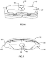
Figures 4-7 are photographs of a brake pad and shim assembly. -
Figures 8-10 are photographs of a brake shim. -
Figures 1 and 3 illustrate a brake backing plate andshim assembly 210 according to one possible embodiment of the present invention.Figure 2 illustrates theassembly 10 of a finished brake pad with shim. The outline of the backing plate is preferably in accordance with the conventional shapes used in disc brake systems (according to standards set by manufacturers for each vehicle make and model). - The
plate 50 is intended to be attached to afriction material 80 to form a brake pad. The plate has ashim facing side 180 and afriction facing side 170.Side 170 of the plate is exposed metal (not covered by friction material), and is substantially flat. The backing plate may haveabutment portions 130 that stick out at the sides to allow the plate (as part of the finished brake pad) to be retained in certain brake calipers (not shown). - The
shim 20, a sheet of thin metal, may be shaped to approximate the shape of the backing plate, as shown inFigure 1 , or it may be somewhat narrower, just covering the central part of the plate. Theshim 20 has a smaller outside periphery than the backing plate. The shim may also be provided with other surface features (including holes or cut-outs 60, as shown inFig. 1 ) to reduce heat or provide other lubricant retaining/distributing areas. - The
shim 20 is retained against theplate 50 bybent tabs 40 on the shim which grip the edges of the plate and hold onto the plate by friction. Thetabs 40 are preferably somewhat flexible allowing theshim 20 to be removed by prying it up and off the backing plate. As shown inFigures 4-7 , the tabs of the shim may hook slightly inwards to better grip the plate. While retained, the shim can also move to a certain extent across the surface ofside 180 of thebacking plate 50, when under braking force, as the tabs are somewhat flexible and springy. - In order to reduce heat buildup and prevent noise and vibration due to the relative movement of the
shim 20 and thebacking plate 50 of thebrake pad assembly 10, lubricant needs to be provided between these components. - Various lubricant types and formulations can be used. The viscosity and formulation should be selected to be suitable for lubricating a brake system (and may be, for example, a high heat bearing automotive lubricant).
- The
shim 20 has a (preferably centrally-located) raised area (or "bubble") 30 that provides an openinterior compartment 120 to accommodate the lubricant. Thebubble 30 may be domed as shown inFigures 4-10 , or may be of another configuration (such as the generally flat-toppedbubble 30 shown inFigures 1-3 ). Portions of theshim 20 beyond the edge of thebubble 30 preferably lie substantially flat against thebacking plate 50, while the bubble stands slightly spaced away from thebacking plate 50 to allow the lubricant to be received in between the two surfaces. The height of the bubble is preferably in the range of about 0.05" to about 0.1", although the selected height and other dimensions of the bubble will necessarily depend on the physical limitations and requirements of the particular application (including, for example the structure of the piston and caliper in the particular vehicle). In one possible embodiment, thebubble 30 may have a substantially flattop surface 150 and sloped or beveled side portions 160 (seeFigure 3 ). - The outside of the
bubble 30 may be any convenient shape - rounded, square, rectangular, triangular. Thepiston 110 should strike on the generallyflat areas 140 of the shim around thebubble 30 and not directly contact thebubble 30. - To
bubble 30 has a (preferably centrally-disposed)access port 90. Theaccess port 90 allows administration oflubricant 70 into thecompartment 120 while theshim 20 is installed in position in thebrake pad assembly 10.Lubricant 70 may be delivered by a service technician using a grease gun 100 (or other lubricant applicator), as understood by persons skilled in the art. One ormore access port 90 openings may be provided in the shim. Oneaccess port 90 may be sufficient for most applications, and may be preferred to best contain the lubricant withincompartment 120. - The
lubricant 70 from thegrease gun 100 flows through theaccess port 90 into thecompartment 120 underbubble portion 30 of the shim. The access port may have turned edges as seen inFig. 3 andFig. 10 in order to guide the flow of lubricant into thecompartment 120 and prevent loss of lubricant through that opening. This can be thought of as an "inverse nipple" shape. Alternatively, the edges of theaccess port 90 could be turned outward ("nipple" shape) as another way of guiding lubricant into the compartment. - The shim and backing plate are not sealed to each other. Accordingly, the lubricant that accumulates in the
compartment 120 seeps out over time to coat the plate-facing side of the shim and the shim-facing side of the backing plate providing a greasy intermediate layer between the shim and backing plate that serves as a noise damping layer. The action of the piston on the slightlyspringy shim 20 may also drive (push) the lubricant out and across the surface of the backing plate. - As needed, the lubricant can be re-applied or topped up to prolong the life of the shim and backing plate. Because of the
convenient access port 90, the shim need not be removed in order to apply fresh lubricant. This facilitates servicing the parts to keep them in good order, and ensures optimal performance over their life-cycle. - The bubble portion of the shim can be press-formed at the same time as the other features (e.g. side tabs) of the shim are formed. This avoids the need to make a second shim in order to create voids in which lubricant can collect. The access port can be formed by drilling or punching the metal of the shim blank, all processes well-understood in the art.
- The foregoing description illustrates only certain preferred embodiments of the invention. The invention is not limited to the foregoing examples. That is, persons skilled in the art will appreciate and understand that modifications and variations are, or will be, possible to utilize and carry out the teachings of the invention described herein. Accordingly, all suitable modifications, variations and equivalents may be resorted to, and such modifications, variations and equivalents are intended to fall within the scope of the invention as described and within the scope of the claims.
Claims (14)
- A shim (20) for a disc brake pad (10), the shim (20) comprising:a generally planar metal sheet, having a plurality of curved or bent edge tabs (40) extending out from the edges thereof for engaging the brake pad (10);characterized in that the sheet has a centrally disposed raised area (30) in which is defined at least one lubricant access port (90); andthe raised area (30) serves as a compartment for a lubricant (70) introduced via the at least one access port (90) while the shim (20) is retained on the brake pad (10).
- The shim of claim 1, wherein the raised area has a flat top surface.
- The shim of claim 1, wherein the raised area has sloped side surfaces.
- The shim of claim 1, wherein the raised area has a generally circular, oval or elliptical shape.
- The shim of claim 1, wherein the raised area has a generally square or rectangular shape.
- The shim of claim 1, wherein the raised area (30) has a domed shape.
- The shim of claim 1, wherein the raised area with the at least one access port has a nipple shape.
- The shim of claim 1, wherein the raised area with the at least one access port has an inverted nipple shape.
- The shim of claim 1, wherein the raised area (30) has exactly one access port (90).
- The shim of claim 1, wherein the at least one access port (90) is circular.
- The shim of claim 1, wherein the at least one access port (90) has edges that are slightly turned in for better retention of lubricant (70).
- The shim of claim 1, wherein the raised area (30) is disposed such that when the shim (20) is installed in a brake assembly having a brake piston, the piston strikes an area of the shim (20) around the raised area (30), and the piston does not contact the raised area (30).
- A shim and brake pad assembly comprising:a shim (20) comprising a generally planar metal sheet, having a plurality of curved or bent edge tabs (40) extending out from the edges thereof; the sheet having a centrally disposed raised area (30) in which is defined at least one lubricant access port (90);a brake pad comprising a backing plate (180) attached to a friction material (80), wherein the edge tabs (40) of the shim (20) grip corresponding edges of the backing plate (180) opposite the friction material (80) to retain the brake pad (10) and shim (20) together in a sandwich;characterized in that the raised area (30) of the shim (20) serves as a compartment for receiving a lubricant (70) introduced via the at least one access port (90), the lubricant (70) being permitted to gradually disperse in the space between the shim (20) and the backing plate (180).
- A method of lubricating a brake pad assembly having an attached tab-type shim, characterized by the steps of:introducing an amount of lubricant via at least one access port defined in a raised area of the shim without removing the shim from the brake pad;the raised area of the shim serving as a compartment for receiving the lubricant and permitting it to gradually disperse in the space between the shim and the brake pad.
Applications Claiming Priority (1)
| Application Number | Priority Date | Filing Date | Title |
|---|---|---|---|
| CA2752900A CA2752900C (en) | 2011-09-19 | 2011-09-19 | Brake shim having lubricant compartment |
Publications (2)
| Publication Number | Publication Date |
|---|---|
| EP2570690A1 EP2570690A1 (en) | 2013-03-20 |
| EP2570690B1 true EP2570690B1 (en) | 2016-01-20 |
Family
ID=46888938
Family Applications (1)
| Application Number | Title | Priority Date | Filing Date |
|---|---|---|---|
| EP12184749.5A Active EP2570690B1 (en) | 2011-09-19 | 2012-09-17 | Brake shim having lubricant compartment |
Country Status (7)
| Country | Link |
|---|---|
| US (1) | US8887876B2 (en) |
| EP (1) | EP2570690B1 (en) |
| JP (1) | JP6169833B2 (en) |
| CN (1) | CN103016575B (en) |
| BR (1) | BR102012023667A2 (en) |
| CA (1) | CA2752900C (en) |
| ES (1) | ES2562160T3 (en) |
Families Citing this family (12)
| Publication number | Priority date | Publication date | Assignee | Title |
|---|---|---|---|---|
| JP5454352B2 (en) * | 2010-05-20 | 2014-03-26 | 株式会社アドヴィックス | Disc brake device |
| CA146223S (en) * | 2012-06-21 | 2013-01-11 | Ray Arbesman | Brake shim |
| CA146221S (en) * | 2012-06-21 | 2013-01-11 | Ray Arbesman | Brake shim |
| CA146220S (en) * | 2012-06-21 | 2013-01-11 | Ray Arbesman | Brake shim |
| CA146222S (en) * | 2012-06-21 | 2013-01-11 | Ray Arbesman | Brake shim |
| CA146224S (en) * | 2012-06-21 | 2013-01-11 | Ray Arbesman | Brake shim |
| JP5845153B2 (en) * | 2012-08-06 | 2016-01-20 | Kyb株式会社 | Caliper brake device |
| US9441687B2 (en) | 2014-03-25 | 2016-09-13 | Wolverine Advanced Materials, Llc | Brake pad assembly with universal shim |
| CN104455098A (en) * | 2014-11-14 | 2015-03-25 | 洪建栋 | Method for reducing braking noise of motor vehicle and noise reducing device using same |
| JP6433262B2 (en) * | 2014-11-21 | 2018-12-05 | 曙ブレーキ工業株式会社 | Shim assembly for disc brake |
| JP6424782B2 (en) * | 2015-09-16 | 2018-11-21 | 株式会社アドヴィックス | Electric parking brake device |
| USD836506S1 (en) | 2016-08-08 | 2018-12-25 | Nucap Industries Inc. | Brake shim |
Family Cites Families (9)
| Publication number | Priority date | Publication date | Assignee | Title |
|---|---|---|---|---|
| JPS5626108Y2 (en) * | 1976-05-19 | 1981-06-20 | ||
| US4155430A (en) * | 1976-05-19 | 1979-05-22 | Toyota Jidosha Kogyo Kabushiki Kaisha | Noise preventing means for disc brakes |
| JPS6058938U (en) * | 1983-09-29 | 1985-04-24 | 住友電気工業株式会社 | Assembly of brake pad and anti-squeal shim in disc brake |
| JPH0714666Y2 (en) * | 1989-12-28 | 1995-04-10 | エヌオーケー株式会社 | Brake pad shims |
| JPH10184744A (en) * | 1996-12-27 | 1998-07-14 | Sumitomo Electric Ind Ltd | Disc brake |
| JP4126962B2 (en) * | 2002-05-31 | 2008-07-30 | 国産部品工業株式会社 | Disc brake |
| JP4715124B2 (en) * | 2004-08-06 | 2011-07-06 | 株式会社アドヴィックス | Laminated shim for disc brake and pad unit having the laminated shim |
| FR2905743B1 (en) * | 2006-09-13 | 2008-12-05 | Bosch Gmbh Robert | BRAKE PAD COMPRISING A GREASE TANK. |
| JP2008256131A (en) * | 2007-04-06 | 2008-10-23 | Advics:Kk | Shim for disk brake pads |
-
2011
- 2011-09-19 CA CA2752900A patent/CA2752900C/en active Active
-
2012
- 2012-09-17 ES ES12184749.5T patent/ES2562160T3/en active Active
- 2012-09-17 EP EP12184749.5A patent/EP2570690B1/en active Active
- 2012-09-17 US US13/621,807 patent/US8887876B2/en active Active
- 2012-09-19 BR BR102012023667A patent/BR102012023667A2/en not_active IP Right Cessation
- 2012-09-19 JP JP2012205913A patent/JP6169833B2/en not_active Expired - Fee Related
- 2012-09-19 CN CN201210350848.8A patent/CN103016575B/en active Active
Also Published As
| Publication number | Publication date |
|---|---|
| CN103016575B (en) | 2017-03-01 |
| CA2752900A1 (en) | 2013-03-19 |
| JP2013064503A (en) | 2013-04-11 |
| US8887876B2 (en) | 2014-11-18 |
| ES2562160T3 (en) | 2016-03-02 |
| BR102012023667A2 (en) | 2014-12-02 |
| CN103016575A (en) | 2013-04-03 |
| CA2752900C (en) | 2017-10-10 |
| EP2570690A1 (en) | 2013-03-20 |
| JP6169833B2 (en) | 2017-07-26 |
| US20130068574A1 (en) | 2013-03-21 |
Similar Documents
| Publication | Publication Date | Title |
|---|---|---|
| CA2752900C (en) | Brake shim having lubricant compartment | |
| US7370736B2 (en) | Laminated shim for disc brake and pad unit having the laminated shim | |
| US6213257B1 (en) | Squeak preventing shim | |
| EP2350489B1 (en) | Piston-side brake shim | |
| JP5855397B2 (en) | Disc brake pad assembly | |
| RU2758167C1 (en) | Floating brake pad | |
| US10054177B2 (en) | Drum brake device and method of assembly | |
| KR20140059144A (en) | Railway vehicle disk brake pad | |
| EP2811195A1 (en) | Railway vehicle disk brake pad | |
| JP2578493Y2 (en) | Disc brake | |
| CN101793298A (en) | Disc brake | |
| CN106133377B (en) | brake pad assembly with universal shim | |
| US8079449B2 (en) | Brake pad comprising a grease reservoir | |
| CN106795926A (en) | Disc brakes | |
| EP0003889A1 (en) | Disc brake caliper assembly | |
| JP2009216121A (en) | Disc brake | |
| US20180172095A1 (en) | Noise reduction clip for brake | |
| US7051848B2 (en) | Temperature specific mechanism retaining brake pads in a caliper assembly during shipping | |
| EP1780437A2 (en) | Flat spring for brake pads used in disc brakes, in particular for industrial vehicles | |
| JP2008256131A (en) | Shim for disk brake pads | |
| CN207278744U (en) | A kind of new and effective brake block | |
| CN107429769B (en) | Multilayer Shims for Disc Brakes |
Legal Events
| Date | Code | Title | Description |
|---|---|---|---|
| PUAI | Public reference made under article 153(3) epc to a published international application that has entered the european phase |
Free format text: ORIGINAL CODE: 0009012 |
|
| AK | Designated contracting states |
Kind code of ref document: A1 Designated state(s): AL AT BE BG CH CY CZ DE DK EE ES FI FR GB GR HR HU IE IS IT LI LT LU LV MC MK MT NL NO PL PT RO RS SE SI SK SM TR |
|
| AX | Request for extension of the european patent |
Extension state: BA ME |
|
| 17P | Request for examination filed |
Effective date: 20130802 |
|
| RBV | Designated contracting states (corrected) |
Designated state(s): AL AT BE BG CH CY CZ DE DK EE ES FI FR GB GR HR HU IE IS IT LI LT LU LV MC MK MT NL NO PL PT RO RS SE SI SK SM TR |
|
| RIC1 | Information provided on ipc code assigned before grant |
Ipc: F16D 65/097 20060101ALI20150512BHEP Ipc: F16D 65/00 20060101AFI20150512BHEP |
|
| GRAP | Despatch of communication of intention to grant a patent |
Free format text: ORIGINAL CODE: EPIDOSNIGR1 |
|
| GRAJ | Information related to disapproval of communication of intention to grant by the applicant or resumption of examination proceedings by the epo deleted |
Free format text: ORIGINAL CODE: EPIDOSDIGR1 |
|
| GRAP | Despatch of communication of intention to grant a patent |
Free format text: ORIGINAL CODE: EPIDOSNIGR1 |
|
| INTG | Intention to grant announced |
Effective date: 20150625 |
|
| INTG | Intention to grant announced |
Effective date: 20150717 |
|
| GRAS | Grant fee paid |
Free format text: ORIGINAL CODE: EPIDOSNIGR3 |
|
| RAP1 | Party data changed (applicant data changed or rights of an application transferred) |
Owner name: NUCAP INDUSTRIES INC. |
|
| RIN1 | Information on inventor provided before grant (corrected) |
Inventor name: ARBESMAN, RAY |
|
| GRAA | (expected) grant |
Free format text: ORIGINAL CODE: 0009210 |
|
| AK | Designated contracting states |
Kind code of ref document: B1 Designated state(s): AL AT BE BG CH CY CZ DE DK EE ES FI FR GB GR HR HU IE IS IT LI LT LU LV MC MK MT NL NO PL PT RO RS SE SI SK SM TR |
|
| REG | Reference to a national code |
Ref country code: GB Ref legal event code: FG4D |
|
| REG | Reference to a national code |
Ref country code: CH Ref legal event code: EP |
|
| REG | Reference to a national code |
Ref country code: IE Ref legal event code: FG4D |
|
| REG | Reference to a national code |
Ref country code: AT Ref legal event code: REF Ref document number: 771880 Country of ref document: AT Kind code of ref document: T Effective date: 20160215 |
|
| REG | Reference to a national code |
Ref country code: ES Ref legal event code: FG2A Ref document number: 2562160 Country of ref document: ES Kind code of ref document: T3 Effective date: 20160302 |
|
| REG | Reference to a national code |
Ref country code: DE Ref legal event code: R096 Ref document number: 602012014062 Country of ref document: DE |
|
| REG | Reference to a national code |
Ref country code: LT Ref legal event code: MG4D Ref country code: NL Ref legal event code: MP Effective date: 20160120 |
|
| REG | Reference to a national code |
Ref country code: AT Ref legal event code: MK05 Ref document number: 771880 Country of ref document: AT Kind code of ref document: T Effective date: 20160120 |
|
| PG25 | Lapsed in a contracting state [announced via postgrant information from national office to epo] |
Ref country code: NL Free format text: LAPSE BECAUSE OF FAILURE TO SUBMIT A TRANSLATION OF THE DESCRIPTION OR TO PAY THE FEE WITHIN THE PRESCRIBED TIME-LIMIT Effective date: 20160120 |
|
| PG25 | Lapsed in a contracting state [announced via postgrant information from national office to epo] |
Ref country code: HR Free format text: LAPSE BECAUSE OF FAILURE TO SUBMIT A TRANSLATION OF THE DESCRIPTION OR TO PAY THE FEE WITHIN THE PRESCRIBED TIME-LIMIT Effective date: 20160120 Ref country code: FI Free format text: LAPSE BECAUSE OF FAILURE TO SUBMIT A TRANSLATION OF THE DESCRIPTION OR TO PAY THE FEE WITHIN THE PRESCRIBED TIME-LIMIT Effective date: 20160120 Ref country code: GR Free format text: LAPSE BECAUSE OF FAILURE TO SUBMIT A TRANSLATION OF THE DESCRIPTION OR TO PAY THE FEE WITHIN THE PRESCRIBED TIME-LIMIT Effective date: 20160421 Ref country code: NO Free format text: LAPSE BECAUSE OF FAILURE TO SUBMIT A TRANSLATION OF THE DESCRIPTION OR TO PAY THE FEE WITHIN THE PRESCRIBED TIME-LIMIT Effective date: 20160420 |
|
| PG25 | Lapsed in a contracting state [announced via postgrant information from national office to epo] |
Ref country code: SE Free format text: LAPSE BECAUSE OF FAILURE TO SUBMIT A TRANSLATION OF THE DESCRIPTION OR TO PAY THE FEE WITHIN THE PRESCRIBED TIME-LIMIT Effective date: 20160120 Ref country code: PT Free format text: LAPSE BECAUSE OF FAILURE TO SUBMIT A TRANSLATION OF THE DESCRIPTION OR TO PAY THE FEE WITHIN THE PRESCRIBED TIME-LIMIT Effective date: 20160520 Ref country code: PL Free format text: LAPSE BECAUSE OF FAILURE TO SUBMIT A TRANSLATION OF THE DESCRIPTION OR TO PAY THE FEE WITHIN THE PRESCRIBED TIME-LIMIT Effective date: 20160120 Ref country code: LV Free format text: LAPSE BECAUSE OF FAILURE TO SUBMIT A TRANSLATION OF THE DESCRIPTION OR TO PAY THE FEE WITHIN THE PRESCRIBED TIME-LIMIT Effective date: 20160120 Ref country code: IS Free format text: LAPSE BECAUSE OF FAILURE TO SUBMIT A TRANSLATION OF THE DESCRIPTION OR TO PAY THE FEE WITHIN THE PRESCRIBED TIME-LIMIT Effective date: 20160520 Ref country code: RS Free format text: LAPSE BECAUSE OF FAILURE TO SUBMIT A TRANSLATION OF THE DESCRIPTION OR TO PAY THE FEE WITHIN THE PRESCRIBED TIME-LIMIT Effective date: 20160120 Ref country code: LT Free format text: LAPSE BECAUSE OF FAILURE TO SUBMIT A TRANSLATION OF THE DESCRIPTION OR TO PAY THE FEE WITHIN THE PRESCRIBED TIME-LIMIT Effective date: 20160120 Ref country code: AT Free format text: LAPSE BECAUSE OF FAILURE TO SUBMIT A TRANSLATION OF THE DESCRIPTION OR TO PAY THE FEE WITHIN THE PRESCRIBED TIME-LIMIT Effective date: 20160120 |
|
| REG | Reference to a national code |
Ref country code: FR Ref legal event code: PLFP Year of fee payment: 5 |
|
| REG | Reference to a national code |
Ref country code: DE Ref legal event code: R097 Ref document number: 602012014062 Country of ref document: DE |
|
| PG25 | Lapsed in a contracting state [announced via postgrant information from national office to epo] |
Ref country code: EE Free format text: LAPSE BECAUSE OF FAILURE TO SUBMIT A TRANSLATION OF THE DESCRIPTION OR TO PAY THE FEE WITHIN THE PRESCRIBED TIME-LIMIT Effective date: 20160120 Ref country code: DK Free format text: LAPSE BECAUSE OF FAILURE TO SUBMIT A TRANSLATION OF THE DESCRIPTION OR TO PAY THE FEE WITHIN THE PRESCRIBED TIME-LIMIT Effective date: 20160120 |
|
| PLBE | No opposition filed within time limit |
Free format text: ORIGINAL CODE: 0009261 |
|
| STAA | Information on the status of an ep patent application or granted ep patent |
Free format text: STATUS: NO OPPOSITION FILED WITHIN TIME LIMIT |
|
| PG25 | Lapsed in a contracting state [announced via postgrant information from national office to epo] |
Ref country code: CZ Free format text: LAPSE BECAUSE OF FAILURE TO SUBMIT A TRANSLATION OF THE DESCRIPTION OR TO PAY THE FEE WITHIN THE PRESCRIBED TIME-LIMIT Effective date: 20160120 Ref country code: SM Free format text: LAPSE BECAUSE OF FAILURE TO SUBMIT A TRANSLATION OF THE DESCRIPTION OR TO PAY THE FEE WITHIN THE PRESCRIBED TIME-LIMIT Effective date: 20160120 Ref country code: SK Free format text: LAPSE BECAUSE OF FAILURE TO SUBMIT A TRANSLATION OF THE DESCRIPTION OR TO PAY THE FEE WITHIN THE PRESCRIBED TIME-LIMIT Effective date: 20160120 Ref country code: RO Free format text: LAPSE BECAUSE OF FAILURE TO SUBMIT A TRANSLATION OF THE DESCRIPTION OR TO PAY THE FEE WITHIN THE PRESCRIBED TIME-LIMIT Effective date: 20160120 |
|
| 26N | No opposition filed |
Effective date: 20161021 |
|
| PG25 | Lapsed in a contracting state [announced via postgrant information from national office to epo] |
Ref country code: BE Free format text: LAPSE BECAUSE OF FAILURE TO SUBMIT A TRANSLATION OF THE DESCRIPTION OR TO PAY THE FEE WITHIN THE PRESCRIBED TIME-LIMIT Effective date: 20160120 |
|
| PG25 | Lapsed in a contracting state [announced via postgrant information from national office to epo] |
Ref country code: SI Free format text: LAPSE BECAUSE OF FAILURE TO SUBMIT A TRANSLATION OF THE DESCRIPTION OR TO PAY THE FEE WITHIN THE PRESCRIBED TIME-LIMIT Effective date: 20160120 Ref country code: BG Free format text: LAPSE BECAUSE OF FAILURE TO SUBMIT A TRANSLATION OF THE DESCRIPTION OR TO PAY THE FEE WITHIN THE PRESCRIBED TIME-LIMIT Effective date: 20160420 |
|
| PG25 | Lapsed in a contracting state [announced via postgrant information from national office to epo] |
Ref country code: MC Free format text: LAPSE BECAUSE OF FAILURE TO SUBMIT A TRANSLATION OF THE DESCRIPTION OR TO PAY THE FEE WITHIN THE PRESCRIBED TIME-LIMIT Effective date: 20160120 |
|
| REG | Reference to a national code |
Ref country code: CH Ref legal event code: PL |
|
| REG | Reference to a national code |
Ref country code: IE Ref legal event code: MM4A |
|
| PG25 | Lapsed in a contracting state [announced via postgrant information from national office to epo] |
Ref country code: CH Free format text: LAPSE BECAUSE OF NON-PAYMENT OF DUE FEES Effective date: 20160930 Ref country code: LI Free format text: LAPSE BECAUSE OF NON-PAYMENT OF DUE FEES Effective date: 20160930 Ref country code: IE Free format text: LAPSE BECAUSE OF NON-PAYMENT OF DUE FEES Effective date: 20160917 |
|
| PG25 | Lapsed in a contracting state [announced via postgrant information from national office to epo] |
Ref country code: LU Free format text: LAPSE BECAUSE OF NON-PAYMENT OF DUE FEES Effective date: 20160917 |
|
| REG | Reference to a national code |
Ref country code: FR Ref legal event code: PLFP Year of fee payment: 6 |
|
| PGFP | Annual fee paid to national office [announced via postgrant information from national office to epo] |
Ref country code: FR Payment date: 20170926 Year of fee payment: 6 Ref country code: IT Payment date: 20170911 Year of fee payment: 6 |
|
| PGFP | Annual fee paid to national office [announced via postgrant information from national office to epo] |
Ref country code: ES Payment date: 20171024 Year of fee payment: 6 |
|
| PG25 | Lapsed in a contracting state [announced via postgrant information from national office to epo] |
Ref country code: CY Free format text: LAPSE BECAUSE OF FAILURE TO SUBMIT A TRANSLATION OF THE DESCRIPTION OR TO PAY THE FEE WITHIN THE PRESCRIBED TIME-LIMIT Effective date: 20160120 Ref country code: HU Free format text: LAPSE BECAUSE OF FAILURE TO SUBMIT A TRANSLATION OF THE DESCRIPTION OR TO PAY THE FEE WITHIN THE PRESCRIBED TIME-LIMIT; INVALID AB INITIO Effective date: 20120917 |
|
| PG25 | Lapsed in a contracting state [announced via postgrant information from national office to epo] |
Ref country code: TR Free format text: LAPSE BECAUSE OF FAILURE TO SUBMIT A TRANSLATION OF THE DESCRIPTION OR TO PAY THE FEE WITHIN THE PRESCRIBED TIME-LIMIT Effective date: 20160120 Ref country code: MK Free format text: LAPSE BECAUSE OF FAILURE TO SUBMIT A TRANSLATION OF THE DESCRIPTION OR TO PAY THE FEE WITHIN THE PRESCRIBED TIME-LIMIT Effective date: 20160120 Ref country code: MT Free format text: LAPSE BECAUSE OF NON-PAYMENT OF DUE FEES Effective date: 20160930 |
|
| PG25 | Lapsed in a contracting state [announced via postgrant information from national office to epo] |
Ref country code: AL Free format text: LAPSE BECAUSE OF FAILURE TO SUBMIT A TRANSLATION OF THE DESCRIPTION OR TO PAY THE FEE WITHIN THE PRESCRIBED TIME-LIMIT Effective date: 20160120 |
|
| PG25 | Lapsed in a contracting state [announced via postgrant information from national office to epo] |
Ref country code: IT Free format text: LAPSE BECAUSE OF NON-PAYMENT OF DUE FEES Effective date: 20180917 |
|
| PG25 | Lapsed in a contracting state [announced via postgrant information from national office to epo] |
Ref country code: FR Free format text: LAPSE BECAUSE OF NON-PAYMENT OF DUE FEES Effective date: 20180930 |
|
| REG | Reference to a national code |
Ref country code: ES Ref legal event code: FD2A Effective date: 20191030 |
|
| PG25 | Lapsed in a contracting state [announced via postgrant information from national office to epo] |
Ref country code: ES Free format text: LAPSE BECAUSE OF NON-PAYMENT OF DUE FEES Effective date: 20180918 |
|
| PGFP | Annual fee paid to national office [announced via postgrant information from national office to epo] |
Ref country code: DE Payment date: 20250923 Year of fee payment: 14 |
|
| PGFP | Annual fee paid to national office [announced via postgrant information from national office to epo] |
Ref country code: GB Payment date: 20250903 Year of fee payment: 14 |