EP2570687A1 - Ball bearing with both sides sealed - Google Patents
Ball bearing with both sides sealed Download PDFInfo
- Publication number
- EP2570687A1 EP2570687A1 EP11780474A EP11780474A EP2570687A1 EP 2570687 A1 EP2570687 A1 EP 2570687A1 EP 11780474 A EP11780474 A EP 11780474A EP 11780474 A EP11780474 A EP 11780474A EP 2570687 A1 EP2570687 A1 EP 2570687A1
- Authority
- EP
- European Patent Office
- Prior art keywords
- seal
- bearing
- ball bearing
- groove
- inwardly extending
- Prior art date
- Legal status (The legal status is an assumption and is not a legal conclusion. Google has not performed a legal analysis and makes no representation as to the accuracy of the status listed.)
- Withdrawn
Links
- 229920001971 elastomer Polymers 0.000 claims abstract description 28
- 229920005989 resin Polymers 0.000 claims abstract description 22
- 239000011347 resin Substances 0.000 claims abstract description 22
- 238000000465 moulding Methods 0.000 claims abstract description 14
- 238000007789 sealing Methods 0.000 claims abstract description 4
- 230000005540 biological transmission Effects 0.000 claims description 12
- 229920000459 Nitrile rubber Polymers 0.000 claims description 9
- 229920000800 acrylic rubber Polymers 0.000 claims description 3
- 229920001973 fluoroelastomer Polymers 0.000 claims description 3
- 229920000058 polyacrylate Polymers 0.000 claims description 3
- XLYOFNOQVPJJNP-UHFFFAOYSA-N water Substances O XLYOFNOQVPJJNP-UHFFFAOYSA-N 0.000 description 9
- 239000004519 grease Substances 0.000 description 5
- 230000001050 lubricating effect Effects 0.000 description 4
- 239000000428 dust Substances 0.000 description 2
- 238000002347 injection Methods 0.000 description 2
- 239000007924 injection Substances 0.000 description 2
- 238000011156 evaluation Methods 0.000 description 1
- 238000001746 injection moulding Methods 0.000 description 1
- 239000002184 metal Substances 0.000 description 1
- 229920003002 synthetic resin Polymers 0.000 description 1
- 239000000057 synthetic resin Substances 0.000 description 1
Images

Classifications
-
- F—MECHANICAL ENGINEERING; LIGHTING; HEATING; WEAPONS; BLASTING
- F16—ENGINEERING ELEMENTS AND UNITS; GENERAL MEASURES FOR PRODUCING AND MAINTAINING EFFECTIVE FUNCTIONING OF MACHINES OR INSTALLATIONS; THERMAL INSULATION IN GENERAL
- F16C—SHAFTS; FLEXIBLE SHAFTS; ELEMENTS OR CRANKSHAFT MECHANISMS; ROTARY BODIES OTHER THAN GEARING ELEMENTS; BEARINGS
- F16C33/00—Parts of bearings; Special methods for making bearings or parts thereof
- F16C33/72—Sealings
- F16C33/76—Sealings of ball or roller bearings
- F16C33/78—Sealings of ball or roller bearings with a diaphragm, disc, or ring, with or without resilient members
- F16C33/7816—Details of the sealing or parts thereof, e.g. geometry, material
- F16C33/782—Details of the sealing or parts thereof, e.g. geometry, material of the sealing region
- F16C33/7823—Details of the sealing or parts thereof, e.g. geometry, material of the sealing region of sealing lips
-
- F—MECHANICAL ENGINEERING; LIGHTING; HEATING; WEAPONS; BLASTING
- F16—ENGINEERING ELEMENTS AND UNITS; GENERAL MEASURES FOR PRODUCING AND MAINTAINING EFFECTIVE FUNCTIONING OF MACHINES OR INSTALLATIONS; THERMAL INSULATION IN GENERAL
- F16C—SHAFTS; FLEXIBLE SHAFTS; ELEMENTS OR CRANKSHAFT MECHANISMS; ROTARY BODIES OTHER THAN GEARING ELEMENTS; BEARINGS
- F16C33/00—Parts of bearings; Special methods for making bearings or parts thereof
- F16C33/72—Sealings
- F16C33/726—Sealings with means to vent the interior of the bearing
-
- F—MECHANICAL ENGINEERING; LIGHTING; HEATING; WEAPONS; BLASTING
- F16—ENGINEERING ELEMENTS AND UNITS; GENERAL MEASURES FOR PRODUCING AND MAINTAINING EFFECTIVE FUNCTIONING OF MACHINES OR INSTALLATIONS; THERMAL INSULATION IN GENERAL
- F16C—SHAFTS; FLEXIBLE SHAFTS; ELEMENTS OR CRANKSHAFT MECHANISMS; ROTARY BODIES OTHER THAN GEARING ELEMENTS; BEARINGS
- F16C33/00—Parts of bearings; Special methods for making bearings or parts thereof
- F16C33/72—Sealings
- F16C33/76—Sealings of ball or roller bearings
- F16C33/78—Sealings of ball or roller bearings with a diaphragm, disc, or ring, with or without resilient members
- F16C33/784—Sealings of ball or roller bearings with a diaphragm, disc, or ring, with or without resilient members mounted to a groove in the inner surface of the outer race and extending toward the inner race
- F16C33/7843—Sealings of ball or roller bearings with a diaphragm, disc, or ring, with or without resilient members mounted to a groove in the inner surface of the outer race and extending toward the inner race with a single annular sealing disc
- F16C33/7853—Sealings of ball or roller bearings with a diaphragm, disc, or ring, with or without resilient members mounted to a groove in the inner surface of the outer race and extending toward the inner race with a single annular sealing disc with one or more sealing lips to contact the inner race
- F16C33/7856—Sealings of ball or roller bearings with a diaphragm, disc, or ring, with or without resilient members mounted to a groove in the inner surface of the outer race and extending toward the inner race with a single annular sealing disc with one or more sealing lips to contact the inner race with a single sealing lip
-
- F—MECHANICAL ENGINEERING; LIGHTING; HEATING; WEAPONS; BLASTING
- F16—ENGINEERING ELEMENTS AND UNITS; GENERAL MEASURES FOR PRODUCING AND MAINTAINING EFFECTIVE FUNCTIONING OF MACHINES OR INSTALLATIONS; THERMAL INSULATION IN GENERAL
- F16J—PISTONS; CYLINDERS; SEALINGS
- F16J15/00—Sealings
- F16J15/16—Sealings between relatively-moving surfaces
- F16J15/164—Sealings between relatively-moving surfaces the sealing action depending on movements; pressure difference, temperature or presence of leaking fluid
-
- F—MECHANICAL ENGINEERING; LIGHTING; HEATING; WEAPONS; BLASTING
- F16—ENGINEERING ELEMENTS AND UNITS; GENERAL MEASURES FOR PRODUCING AND MAINTAINING EFFECTIVE FUNCTIONING OF MACHINES OR INSTALLATIONS; THERMAL INSULATION IN GENERAL
- F16J—PISTONS; CYLINDERS; SEALINGS
- F16J15/00—Sealings
- F16J15/16—Sealings between relatively-moving surfaces
- F16J15/34—Sealings between relatively-moving surfaces with slip-ring pressed against a more or less radial face on one member
- F16J15/3436—Pressing means
- F16J15/3456—Pressing means without external means for pressing the ring against the face, e.g. slip-ring with a resilient lip
-
- F—MECHANICAL ENGINEERING; LIGHTING; HEATING; WEAPONS; BLASTING
- F16—ENGINEERING ELEMENTS AND UNITS; GENERAL MEASURES FOR PRODUCING AND MAINTAINING EFFECTIVE FUNCTIONING OF MACHINES OR INSTALLATIONS; THERMAL INSULATION IN GENERAL
- F16C—SHAFTS; FLEXIBLE SHAFTS; ELEMENTS OR CRANKSHAFT MECHANISMS; ROTARY BODIES OTHER THAN GEARING ELEMENTS; BEARINGS
- F16C19/00—Bearings with rolling contact, for exclusively rotary movement
- F16C19/02—Bearings with rolling contact, for exclusively rotary movement with bearing balls essentially of the same size in one or more circular rows
- F16C19/04—Bearings with rolling contact, for exclusively rotary movement with bearing balls essentially of the same size in one or more circular rows for radial load mainly
- F16C19/06—Bearings with rolling contact, for exclusively rotary movement with bearing balls essentially of the same size in one or more circular rows for radial load mainly with a single row or balls
-
- F—MECHANICAL ENGINEERING; LIGHTING; HEATING; WEAPONS; BLASTING
- F16—ENGINEERING ELEMENTS AND UNITS; GENERAL MEASURES FOR PRODUCING AND MAINTAINING EFFECTIVE FUNCTIONING OF MACHINES OR INSTALLATIONS; THERMAL INSULATION IN GENERAL
- F16C—SHAFTS; FLEXIBLE SHAFTS; ELEMENTS OR CRANKSHAFT MECHANISMS; ROTARY BODIES OTHER THAN GEARING ELEMENTS; BEARINGS
- F16C2226/00—Joining parts; Fastening; Assembling or mounting parts
- F16C2226/30—Material joints
-
- F—MECHANICAL ENGINEERING; LIGHTING; HEATING; WEAPONS; BLASTING
- F16—ENGINEERING ELEMENTS AND UNITS; GENERAL MEASURES FOR PRODUCING AND MAINTAINING EFFECTIVE FUNCTIONING OF MACHINES OR INSTALLATIONS; THERMAL INSULATION IN GENERAL
- F16C—SHAFTS; FLEXIBLE SHAFTS; ELEMENTS OR CRANKSHAFT MECHANISMS; ROTARY BODIES OTHER THAN GEARING ELEMENTS; BEARINGS
- F16C2240/00—Specified values or numerical ranges of parameters; Relations between them
- F16C2240/40—Linear dimensions, e.g. length, radius, thickness, gap
- F16C2240/42—Groove sizes
-
- F—MECHANICAL ENGINEERING; LIGHTING; HEATING; WEAPONS; BLASTING
- F16—ENGINEERING ELEMENTS AND UNITS; GENERAL MEASURES FOR PRODUCING AND MAINTAINING EFFECTIVE FUNCTIONING OF MACHINES OR INSTALLATIONS; THERMAL INSULATION IN GENERAL
- F16C—SHAFTS; FLEXIBLE SHAFTS; ELEMENTS OR CRANKSHAFT MECHANISMS; ROTARY BODIES OTHER THAN GEARING ELEMENTS; BEARINGS
- F16C2361/00—Apparatus or articles in engineering in general
- F16C2361/63—Gears with belts and pulleys
-
- F—MECHANICAL ENGINEERING; LIGHTING; HEATING; WEAPONS; BLASTING
- F16—ENGINEERING ELEMENTS AND UNITS; GENERAL MEASURES FOR PRODUCING AND MAINTAINING EFFECTIVE FUNCTIONING OF MACHINES OR INSTALLATIONS; THERMAL INSULATION IN GENERAL
- F16C—SHAFTS; FLEXIBLE SHAFTS; ELEMENTS OR CRANKSHAFT MECHANISMS; ROTARY BODIES OTHER THAN GEARING ELEMENTS; BEARINGS
- F16C33/00—Parts of bearings; Special methods for making bearings or parts thereof
- F16C33/72—Sealings
- F16C33/76—Sealings of ball or roller bearings
- F16C33/80—Labyrinth sealings
- F16C33/805—Labyrinth sealings in addition to other sealings, e.g. dirt guards to protect sealings with sealing lips
-
- F—MECHANICAL ENGINEERING; LIGHTING; HEATING; WEAPONS; BLASTING
- F16—ENGINEERING ELEMENTS AND UNITS; GENERAL MEASURES FOR PRODUCING AND MAINTAINING EFFECTIVE FUNCTIONING OF MACHINES OR INSTALLATIONS; THERMAL INSULATION IN GENERAL
- F16C—SHAFTS; FLEXIBLE SHAFTS; ELEMENTS OR CRANKSHAFT MECHANISMS; ROTARY BODIES OTHER THAN GEARING ELEMENTS; BEARINGS
- F16C35/00—Rigid support of bearing units; Housings, e.g. caps, covers
- F16C35/04—Rigid support of bearing units; Housings, e.g. caps, covers in the case of ball or roller bearings
- F16C35/06—Mounting or dismounting of ball or roller bearings; Fixing them onto shaft or in housing
- F16C35/067—Fixing them in a housing
-
- F—MECHANICAL ENGINEERING; LIGHTING; HEATING; WEAPONS; BLASTING
- F16—ENGINEERING ELEMENTS AND UNITS; GENERAL MEASURES FOR PRODUCING AND MAINTAINING EFFECTIVE FUNCTIONING OF MACHINES OR INSTALLATIONS; THERMAL INSULATION IN GENERAL
- F16H—GEARING
- F16H55/00—Elements with teeth or friction surfaces for conveying motion; Worms, pulleys or sheaves for gearing mechanisms
- F16H55/32—Friction members
- F16H55/36—Pulleys
Definitions
- This invention relates to ball bearing with seals on both sides which includes a torque transmission member formed on the outer race by resin molding, such as a resin pulley for guiding a timing belt for driving camshafts in an automotive engine or a belt for driving engine accessories.
- One known pulley for guiding a timing belt for driving camshafts is a resin pulley as disclosed in Patent document 1, which includes a ball bearing, and a belt guide ring made of a synthetic resin and formed on the radially outer surface of the outer race of the ball bearing by e.g. injection molding.
- the ball bearing Since this resin pulley is exposed to the atmosphere around the engine, the ball bearing has seals on both sides to prevent entry of splashed muddy water into the bearing and to prevent lubricating grease from leaking out.
- a rubber seal has its radially outer portion fitted in each of seal engaging grooves formed on the radially inner surface of the outer race at its respective ends, and includes an inwardly extending lip formed at the radially inner portion of the rubber seal with its tip elastically pressed against the inner side surface of one of seal grooves formed on the radially outer surface of the inner race at its respective ends.
- the increased inner pressure also increases the contact pressure of the inwardly extending lips and thus accelerates wear of the contact portions of the lips, which deteriorates the durability of the seals.
- An object of this invention is to provide a ball bearing with seals on both sides which is configured such that the pressure in the bearing interior is less likely to drop when the torque transmission member such as the belt guide ring cools after it has been formed by resin molding, thus preventing the inwardly extending lip of each rubber seal from being pressed against the inner side surface of the seal groove, and which is high in sealability.
- the present invention provides a ball bearing with seals on both sides, comprising an outer race formed with two seal fitting grooves on a radially inner surface of the outer race, each at one of two end portions of the outer race, a torque transmission member formed on a radially outer surface of the outer race by resin molding, an inner race provided radially inwardly of the outer race and formed with two seal grooves on a radially outer surface of the inner race, each at one of two end portions of the inner race, and rubber seals each having a radially outer portion fitted in the corresponding seal fitting groove, and having an inwardly extending lip having a tip which is kept in elastic contact with an inner side surface of the corresponding seal groove, thereby sealing the bearing interior, wherein a contact surface of the inwardly extending seal lip which is in elastic contact with the inner side surface of the seal groove is formed with a recess extending a limited circumferential range of the contact surface and defining a minute gap in cooperation with the inner side surface of the seal
- the recess By forming the recess in the contact surface of the inwardly extending lip that is brought into elastic contact with the inner side surface of the seal groove, the recess defines the above-mentioned gap, through which bearing interior communicates with the exterior of the bearing.
- the recess formed in the inwardly extending lip is not limited in shape, and may be an arcuate groove or a rectangular groove. The deeper this groove, the more likely foreign matter such as dust and water is to enter the bearing and also the more likely bearing lubricating grease is to leak out. But if the groove is too shallow, the groove may not serve as a vent passage for equalizing the pressure between the interior and exterior of the bearing. All considered, the recess has preferably a depth h of 0.01 to 0.08 mm.
- the rubber seals of the ball bearing according to the present invention are heated when the rubber seals are in contact with the bearing lubricating grease or the torque transmission member is formed by resin molding, the rubber seals are preferably made of a rubber which is resistant to oil and heat, such as nitrile rubber, heat-resistant nitrile rubber, hydrogenated nitrile rubber, acrylic rubber, or fluororubber.
- the torque transmission member formed on the radially outer surface of the outer race may be a pulley or a roller.
- each rubber seal has an inwardly extending lip at its radially inner portion, the lip having a contact surface which is in elastic contact with the inner side surface of a seal groove of the inner race and which is formed with a recess extending a limited circumferential range of the contact surface and defining a minute gap in cooperation with the inner side surface of the seal groove.
- the recess minimizes reduction in pressure in the bearing interior when the bearing cools down after resin molding. This prevents the inwardly extending lips from being pressed against the inner side surfaces of the respective seal grooves of the inner race, which in turn prevents an increase in torque loss.
- the gap defined by the recess and the inner side surface of the seal groove is so small that the gap never impairs sealability of the bearing.
- the recess eventually disappears, allowing the tip of the inwardly extending lip to come into contact with the inner side surface of the seal groove over the entire surface of the tip of the lip.
- the sealability improves gradually with the passage of time.
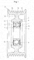
- Fig. 1 shows a resin pulley including the ball bearing with seals on both sides according to the present invention.
- the resin pulley includes, besides the ball bearing 1, a belt guiding ring 21 formed on the radially outer surface of the ball bearing 1 as a torque transmission member.
- the belt guiding ring 21 comprises a boss portion 22 enclosing the radially outer portions of the respective side surfaces of the ball bearing 1 and its radially outer surface, a disk portion 23 extending radially outwardly from the radially outer surface of the boss portion 22, and a rim portion 24 extending in both axial directions from the radially outer portion of the disk portion 23.
- the rim portion 24 has a plurality of rows of V-shaped grooves on its radially outer surface.
- the belt guiding ring 21 is formed by injecting molten resin into a cavity of a mold with the ball bearing 1 fixed in position in the mold such that the cavity is located radially outwardly of the ball bearing 1.
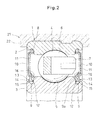
- the ball bearing 1 comprises an outer race 2 having a raceway 4 formed on its radially inner surface, an inner race 3 having a raceway 5 formed on its radially outer surface, a plurality of balls 6 mounted between the raceways 4 and 5, and a retainer 7 retaining the balls 6.
- Two seal fitting grooves 8 are formed on the radially inner surface of the outer race 2 at the respective axial end portions.
- Two seal grooves 9 are formed on the radially outer surface of the inner race 3 that are radially opposed to the respective seal fitting grooves 8.
- a rubber seal 10 is fitted at its radially outer portion in each of the two seal fitting grooves 8 formed on the outer race 2.
- the rubber seals 10 are made of an oil-resistant and heat-resistant rubber such as nitrile rubber, heat-resistant nitrile rubber, hydrogenated nitrile rubber, acrylic rubber and fluororubber, and each reinforced by a metal core 11.
- the rubber seals 10 each include an inwardly extending lip 12 and an outwardly extending lip 13, at its radially inner portion.
- the outwardly extending lip 13 defines a labyrinth 15 in cooperation with a small-diameter cylindrical surface 14 formed on the axially outer portion of the seal groove 9.
- the rubber seals 10 each further include an annular protrusion 16 on its axially inner surface at its radially inner portion.
- the protrusion 16 defines a labyrinth 17 in cooperation with shoulder 9b formed on the inner side surface 9a of seal groove 9 at its radially outer portion.
- the inwardly extending lip 12 has its tip elastically in contact with the inner side surface 9a of the seal groove 9, and is formed with a recess 18 in its contact surface so as to extend a limited circumferential range.
- the recess 18 defines a minute gap in cooperation with the inner side surface 9a through which the bearing interior communicates with the exterior of the bearing.
- the recess may be an arcuate groove as shown in Fig. 4(I) or a rectangular groove as shown in Fig. 4(II) .
- the recess 18 If the recess 18 is too deep and too wide in the circumferential direction, sealability deteriorates, allowing entry of foreign matter such as dust and water into the bearing, or leakage of bearing lubricating grease in the bearing to the outside of the bearing. If the recess 18 is smaller than necessary, the recess 18 will not serve the purpose as a passage for equalizing the pressures in and out of the bearing.
- the recess 18 is an arcuate groove, the recess 18 has a depth h of 0.01 to 0.08 mm at its circumferential center, and a width W of 0.2 to 0.8 mm. If the recess 18 is a rectangular groove, the recess 18 has a depth h of 0.01 to 0.08 mm and a width W of 0.2 to 0.8 mm.
- the bearing interior communicates with the exterior of the bearing through the gap defined by the recess 18. If the temperature and thus the pressure in the bearing interior rises when forming the belt guiding ring 21 on the radially outer surface of the outer race 2 by resin molding, the pressure is released to the outside through the gap defined by the recess 18.
- the pressure in the bearing interior never rises and is kept at a constant level.
- the pressure in the bearing interior is kept at the constant level. This prevents the inwardly extending lip 12 of the rubber seal 10 from getting sucked onto the inner side surface 9a of the seal groove 9, which in turn prevents an increase in torque loss while the bearing is rotating.
- Revolving speed 1500 rpm Radial load: 294 N Water injection rate: 200 ml/minute Operating period: 5 minutes [Table 1] Muddy water test Bearing No. Seal No, Depth of slit Water content in grease Evaluation A A-1 0.06 0.11 ⁇ A-2 0.06 B B-1 0.1 5.9 ⁇ B-2 0.1 C C-1 0.06 0.04 ⁇ C-2 0.06 D D-1 0.06 0.04 ⁇ D-2 0.06 E E-1 0.08 0.04 ⁇ E-2 0.08 [Test conditions] Revolving speed: 1500 rpm; Radial load: 294 N; Water injection rate: 200 ml/min; Operating period: 5 min
- test results show that by setting the depth h of the recess 18 at 0.08 mm or less, it is possible to prevent entry of water, and thus ensure enough sealability.
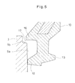
- the depth h of the recess 18 By setting the depth h of the recess 18 at 0.08 mm or less, when the tip of the inwardly extending lip 12 gradually becomes worn while the bearing is rotating due to contact with the inner side surface 9a of the seal groove 9, the recess 18 disappears as shown in Fig. 5 , allowing the tip of the inwardly extending lip 12 to come into contact with the inner side surface 9a of the seal groove 9 over the entire surface of the tip of the lip 12. This means that the sealability improves gradually with the passage of time.
- the torque transmission member formed on the radially outer surface of the outer race 2 by resin molding is the belt guiding ring 21.
- the torque transmission member according to the invention is not limited to the belt guiding ring 21 but may be e.g. a roller.
Landscapes
- Engineering & Computer Science (AREA)
- General Engineering & Computer Science (AREA)
- Mechanical Engineering (AREA)
- Sealing Of Bearings (AREA)
- Rolling Contact Bearings (AREA)
- Pulleys (AREA)
Abstract
A ball bearing with seals on both sides is provided which is configured such that the pressure in the bearing interior is less likely to drop when a belt guide ring cools after it has been formed by resin molding, thus preventing the inwardly extending lip of each rubber seal from being pressed against the inner side surface of the seal groove. The belt guide ring (21) is formed on the radially outer surface of an outer race (2) of the bearing. Seal fitting grooves (8) are formed on the radially inner surface of the outer race (2) at its respective end portions. A rubber seal (10) has its radially outer portion fitted in each seal fitting groove (8). The rubber seal (10) has an inwardly extending lip (12) formed at its radially inner portion and having its tip elastically kept in contact with an inner side surface of one of two seal grooves (9) formed on the radially inner surface of an inner race (3) of the bearing, thereby sealing the bearing interior, and having an inwardly extending lip (12) having a tip which is kept in elastic contact with an inner side surface (9a) of the corresponding seal groove (9), thereby sealing the bearing interior. The contact surface of the inwardly extending seal lip (12) which is in elastic contact with the inner side surface (9a) of the seal groove (9) is formed with a recess (18) extending a limited circumferential range of the contact surface and defining a minute gap in cooperation with the inner side surface (9a) of the seal groove (9). With this arrangement, when the temperature and thus the pressure in the bearing interior rises when the belt guide ring (21) is formed by resin molding, the pressure is released to the exterior of the bearing through the gap defined by the recess (18). The pressure in the bearing interior is thus kept constant when the guide ring cools down after resin molding. This prevents the inwardly extending lip (12) from being pressed hard against the inner side surface (9a) of the seal groove (9) of the inner race (3).
Description
- This invention relates to ball bearing with seals on both sides which includes a torque transmission member formed on the outer race by resin molding, such as a resin pulley for guiding a timing belt for driving camshafts in an automotive engine or a belt for driving engine accessories.
- One known pulley for guiding a timing belt for driving camshafts is a resin pulley as disclosed in
Patent document 1, which includes a ball bearing, and a belt guide ring made of a synthetic resin and formed on the radially outer surface of the outer race of the ball bearing by e.g. injection molding. - Since this resin pulley is exposed to the atmosphere around the engine, the ball bearing has seals on both sides to prevent entry of splashed muddy water into the bearing and to prevent lubricating grease from leaking out.
-
- Patent document 1:
JP Patent Publication 2008-151258A - With such conventional ball bearings with seals on both sides, a rubber seal has its radially outer portion fitted in each of seal engaging grooves formed on the radially inner surface of the outer race at its respective ends, and includes an inwardly extending lip formed at the radially inner portion of the rubber seal with its tip elastically pressed against the inner side surface of one of seal grooves formed on the radially outer surface of the inner race at its respective ends. In this arrangement, since the bearing interior is completely sealed, when the belt guiding ring is formed on the outer race by resin molding, the temperature and thus the pressure in the bearing interior rise, and then when the resin cools, the pressure in the bearing interior drops. When the pressure in the bearing interior drops, the rubber seals are elastically deformed inwardly. This could cause the inwardly extending lip of each rubber seal to be elastically pressed hard against the inner side surface of the seal groove, which could in turn increase torque loss.
- The increased inner pressure also increases the contact pressure of the inwardly extending lips and thus accelerates wear of the contact portions of the lips, which deteriorates the durability of the seals.
- An object of this invention is to provide a ball bearing with seals on both sides which is configured such that the pressure in the bearing interior is less likely to drop when the torque transmission member such as the belt guide ring cools after it has been formed by resin molding, thus preventing the inwardly extending lip of each rubber seal from being pressed against the inner side surface of the seal groove, and which is high in sealability.
- In order to achieve the above object, the present invention provides a ball bearing with seals on both sides, comprising an outer race formed with two seal fitting grooves on a radially inner surface of the outer race, each at one of two end portions of the outer race, a torque transmission member formed on a radially outer surface of the outer race by resin molding, an inner race provided radially inwardly of the outer race and formed with two seal grooves on a radially outer surface of the inner race, each at one of two end portions of the inner race, and rubber seals each having a radially outer portion fitted in the corresponding seal fitting groove, and having an inwardly extending lip having a tip which is kept in elastic contact with an inner side surface of the corresponding seal groove, thereby sealing the bearing interior, wherein a contact surface of the inwardly extending seal lip which is in elastic contact with the inner side surface of the seal groove is formed with a recess extending a limited circumferential range of the contact surface and defining a minute gap in cooperation with the inner side surface of the seal groove.
- By forming the recess in the contact surface of the inwardly extending lip that is brought into elastic contact with the inner side surface of the seal groove, the recess defines the above-mentioned gap, through which bearing interior communicates with the exterior of the bearing. Thus, when the temperature and thus the pressure in the bearing interior rises when the torque transmission member is formed on the radially outer surface of the outer race, the pressure is released to the exterior of the bearing through the gap.
- This prevents an increase in pressure in the bearing interior, and the pressure in the bearing interior is kept constant even when the bearing cools down after resin molding, thus preventing the inwardly extending lip of each rubber seal from being attracted to and pressed against the inner side surface of the seal groove of the inner race. This in turn prevents increase in torque loss during operation of the bearing.
- The recess formed in the inwardly extending lip is not limited in shape, and may be an arcuate groove or a rectangular groove. The deeper this groove, the more likely foreign matter such as dust and water is to enter the bearing and also the more likely bearing lubricating grease is to leak out. But if the groove is too shallow, the groove may not serve as a vent passage for equalizing the pressure between the interior and exterior of the bearing. All considered, the recess has preferably a depth h of 0.01 to 0.08 mm.
- Since the rubber seals of the ball bearing according to the present invention are heated when the rubber seals are in contact with the bearing lubricating grease or the torque transmission member is formed by resin molding, the rubber seals are preferably made of a rubber which is resistant to oil and heat, such as nitrile rubber, heat-resistant nitrile rubber, hydrogenated nitrile rubber, acrylic rubber, or fluororubber.
- The torque transmission member formed on the radially outer surface of the outer race may be a pulley or a roller.
- According to the present invention, each rubber seal has an inwardly extending lip at its radially inner portion, the lip having a contact surface which is in elastic contact with the inner side surface of a seal groove of the inner race and which is formed with a recess extending a limited circumferential range of the contact surface and defining a minute gap in cooperation with the inner side surface of the seal groove. The recess minimizes reduction in pressure in the bearing interior when the bearing cools down after resin molding. This prevents the inwardly extending lips from being pressed against the inner side surfaces of the respective seal grooves of the inner race, which in turn prevents an increase in torque loss.
- The gap defined by the recess and the inner side surface of the seal groove is so small that the gap never impairs sealability of the bearing. As the tip of the inwardly extending lip gradually becomes worn while the bearing is rotating due to contact with the inner side surface of the seal groove, the recess eventually disappears, allowing the tip of the inwardly extending lip to come into contact with the inner side surface of the seal groove over the entire surface of the tip of the lip. Thus, the sealability improves gradually with the passage of time.
-
-
Fig. 1 is a vertical sectional front view of a resin pulley including a ball bearing with seals on both sides according to the present invention. -
Fig. 2 is a partial enlarged sectional view of the ball bearing ofFig. 1 . -
Fig. 3 is an enlarged sectional view of an inwardly extending lip shown inFig. 2 . -
Fig. 4(I) is a sectional view taken along line IV-IV ofFig. 3; and Fig. 4(II) is a similar sectional view showing a different recess. -
Fig. 5 is a sectional view of the inwardly extending lip after the recess has disappeared. - The embodiment of the present invention is described with reference to the drawings.
Fig. 1 shows a resin pulley including the ball bearing with seals on both sides according to the present invention. The resin pulley includes, besides the ball bearing 1, abelt guiding ring 21 formed on the radially outer surface of the ball bearing 1 as a torque transmission member. - The
belt guiding ring 21 comprises aboss portion 22 enclosing the radially outer portions of the respective side surfaces of the ball bearing 1 and its radially outer surface, adisk portion 23 extending radially outwardly from the radially outer surface of theboss portion 22, and arim portion 24 extending in both axial directions from the radially outer portion of thedisk portion 23. Therim portion 24 has a plurality of rows of V-shaped grooves on its radially outer surface. - The
belt guiding ring 21 is formed by injecting molten resin into a cavity of a mold with the ball bearing 1 fixed in position in the mold such that the cavity is located radially outwardly of the ball bearing 1. - The ball bearing 1 comprises an
outer race 2 having araceway 4 formed on its radially inner surface, aninner race 3 having a raceway 5 formed on its radially outer surface, a plurality ofballs 6 mounted between theraceways 4 and 5, and aretainer 7 retaining theballs 6. - Two seal fitting grooves 8 are formed on the radially inner surface of the
outer race 2 at the respective axial end portions. Twoseal grooves 9 are formed on the radially outer surface of theinner race 3 that are radially opposed to the respective seal fitting grooves 8. - A
rubber seal 10 is fitted at its radially outer portion in each of the two seal fitting grooves 8 formed on theouter race 2. Therubber seals 10 are made of an oil-resistant and heat-resistant rubber such as nitrile rubber, heat-resistant nitrile rubber, hydrogenated nitrile rubber, acrylic rubber and fluororubber, and each reinforced by ametal core 11. - As shown in
Figs. 2 and3 , therubber seals 10 each include an inwardly extendinglip 12 and an outwardly extendinglip 13, at its radially inner portion. The outwardly extendinglip 13 defines alabyrinth 15 in cooperation with a small-diametercylindrical surface 14 formed on the axially outer portion of theseal groove 9. Therubber seals 10 each further include anannular protrusion 16 on its axially inner surface at its radially inner portion. Theprotrusion 16 defines alabyrinth 17 in cooperation withshoulder 9b formed on theinner side surface 9a ofseal groove 9 at its radially outer portion. - As shown in
Fig. 3 , the inwardly extendinglip 12 has its tip elastically in contact with theinner side surface 9a of theseal groove 9, and is formed with arecess 18 in its contact surface so as to extend a limited circumferential range. Therecess 18 defines a minute gap in cooperation with theinner side surface 9a through which the bearing interior communicates with the exterior of the bearing. - The recess may be an arcuate groove as shown in
Fig. 4(I) or a rectangular groove as shown inFig. 4(II) . - If the
recess 18 is too deep and too wide in the circumferential direction, sealability deteriorates, allowing entry of foreign matter such as dust and water into the bearing, or leakage of bearing lubricating grease in the bearing to the outside of the bearing. If therecess 18 is smaller than necessary, therecess 18 will not serve the purpose as a passage for equalizing the pressures in and out of the bearing. - In order to avoid these problems, if the
recess 18 is an arcuate groove, therecess 18 has a depth h of 0.01 to 0.08 mm at its circumferential center, and a width W of 0.2 to 0.8 mm. If therecess 18 is a rectangular groove, therecess 18 has a depth h of 0.01 to 0.08 mm and a width W of 0.2 to 0.8 mm. - By forming the
recess 18 in the contact surface of the inwardly extendinglip 12 that is in elastic contact with theinner side surface 9a of theseal groove 9, the bearing interior communicates with the exterior of the bearing through the gap defined by therecess 18. If the temperature and thus the pressure in the bearing interior rises when forming thebelt guiding ring 21 on the radially outer surface of theouter race 2 by resin molding, the pressure is released to the outside through the gap defined by therecess 18. - The pressure in the bearing interior never rises and is kept at a constant level. When the bearing is cooled down after resin molding, too, the pressure in the bearing interior is kept at the constant level. This prevents the inwardly extending
lip 12 of therubber seal 10 from getting sucked onto theinner side surface 9a of theseal groove 9, which in turn prevents an increase in torque loss while the bearing is rotating. - In order to determine the influence of the depth h of the
recess 18, bearing samples having recesses whose depths differ from one another were prepared and subjected to a water resistance test. Table 1 shows the results of the test. The test conditions are shown below: -
Revolving speed: 1500 rpm
Radial load: 294 N
Water injection rate: 200 ml/minute
Operating period: 5 minutes[Table 1] Muddy water test Bearing No. Seal No, Depth of slit Water content in grease Evaluation A A-1 0.06 0.11 ○ A-2 0.06 B B-1 0.1 5.9 × B-2 0.1 C C-1 0.06 0.04 ○ C-2 0.06 D D-1 0.06 0.04 ○ D-2 0.06 E E-1 0.08 0.04 ○ E-2 0.08
[Test conditions] Revolving speed: 1500 rpm; Radial load: 294 N; Water injection rate: 200 ml/min; Operating period: 5 min - The test results show that by setting the depth h of the
recess 18 at 0.08 mm or less, it is possible to prevent entry of water, and thus ensure enough sealability. - By setting the depth h of the
recess 18 at 0.08 mm or less, when the tip of the inwardly extendinglip 12 gradually becomes worn while the bearing is rotating due to contact with theinner side surface 9a of theseal groove 9, therecess 18 disappears as shown inFig. 5 , allowing the tip of the inwardly extendinglip 12 to come into contact with theinner side surface 9a of theseal groove 9 over the entire surface of the tip of thelip 12. This means that the sealability improves gradually with the passage of time. - In the embodiment, the torque transmission member formed on the radially outer surface of the
outer race 2 by resin molding is thebelt guiding ring 21. But the torque transmission member according to the invention is not limited to thebelt guiding ring 21 but may be e.g. a roller. -
- 2. Outer race
- 3. Inner race
- 8. Seal fitting groove
- 9. Seal groove
- 9a. Inner side surface
- 10. Rubber seal
- 12. Inwardly extending lip
- 18. Recess
- 21. Belt guiding ring (torque transmission member)
Claims (9)
- A ball bearing with seals on both sides, comprising an outer race formed with two seal fitting grooves on a radially inner surface of the outer race, each at one of two end portions of the outer race, a torque transmission member formed on a radially outer surface of the outer race by resin molding, an inner race provided radially inwardly of the outer race and formed with two seal grooves on a radially outer surface of the inner race, each at one of two end portions of the inner race, and rubber seals each having a radially outer portion fitted in the corresponding seal fitting groove, and having an inwardly extending lip having a tip which is kept in elastic contact with an inner side surface of the corresponding seal groove, thereby sealing the bearing interior, characterized in that a contact surface of the inwardly extending seal lip which is in elastic contact with the inner side surface of the seal groove is formed with a recess extending a limited circumferential range of the contact surface and defining a minute gap in cooperation with the inner side surface of the seal groove.
- The ball bearing of claim 1, wherein the recess is an arcuate groove having a depth h of 0.01 to 0.08 mm at a circumferential center of the groove.
- The ball bearing of claim 1, wherein the recess is a rectangular groove having a depth h of 0.01 to 0.08 mm.
- The ball bearing of any of claims 1 to 3, wherein the rubber seals are made of nitrile rubber.
- The ball bearing of any of claims 1 to 3, wherein the rubber seals are made of heat-resistant nitrile rubber.
- The ball bearing of any of claims 1 to 3, wherein the rubber seals are made of hydrogenated nitrile rubber.
- The ball bearing of any of claims 1 to 3, wherein the rubber seals are made of acrylic rubber.
- The ball bearing of any of claims 1 to 3, wherein the rubber seals are made of fluororubber.
- The ball bearing of any of claims 1 to 3, wherein the torque transmission member is a pulley.
Applications Claiming Priority (2)
| Application Number | Priority Date | Filing Date | Title |
|---|---|---|---|
| JP2010109349A JP2011236983A (en) | 2010-05-11 | 2010-05-11 | Ball bearing with both sides sealed |
| PCT/JP2011/059593 WO2011142217A1 (en) | 2010-05-11 | 2011-04-19 | Ball bearing with both sides sealed |
Publications (1)
| Publication Number | Publication Date |
|---|---|
| EP2570687A1 true EP2570687A1 (en) | 2013-03-20 |
Family
ID=44914273
Family Applications (1)
| Application Number | Title | Priority Date | Filing Date |
|---|---|---|---|
| EP11780474A Withdrawn EP2570687A1 (en) | 2010-05-11 | 2011-04-19 | Ball bearing with both sides sealed |
Country Status (5)
| Country | Link |
|---|---|
| US (1) | US20130051718A1 (en) |
| EP (1) | EP2570687A1 (en) |
| JP (1) | JP2011236983A (en) |
| CN (1) | CN102906434A (en) |
| WO (1) | WO2011142217A1 (en) |
Families Citing this family (3)
| Publication number | Priority date | Publication date | Assignee | Title |
|---|---|---|---|---|
| US10550893B2 (en) * | 2017-04-19 | 2020-02-04 | Seiko Instruments Inc. | Rolling bearing |
| JP7269048B2 (en) * | 2019-03-22 | 2023-05-08 | 株式会社栗本鐵工所 | Seal structure of rotating shaft of magneto-rheological fluid device |
| CN111520399A (en) * | 2020-04-20 | 2020-08-11 | 人本集团有限公司 | Novel deep groove ball bearing |
Family Cites Families (16)
| Publication number | Priority date | Publication date | Assignee | Title |
|---|---|---|---|---|
| GB2114682B (en) * | 1982-02-09 | 1985-09-11 | Skf Svenska Kullagerfab Ab | Rolling bearing assemblies fitted with seals |
| JPH0419423A (en) * | 1990-05-14 | 1992-01-23 | Ntn Corp | Seal device for rolling bearing |
| JPH11193795A (en) * | 1997-12-26 | 1999-07-21 | Nippon Seiko Kk | Bearing seal device for water pump |
| JP2000179560A (en) * | 1998-12-18 | 2000-06-27 | Ntn Corp | Bearing for flywheel damper |
| JP2002372131A (en) * | 2001-06-18 | 2002-12-26 | Koyo Seiko Co Ltd | Bearing with resin pulley |
| US7325974B2 (en) * | 2001-09-18 | 2008-02-05 | Nsk Ltd. | Pulley rotation support apparatus |
| EP1429042A4 (en) * | 2001-09-18 | 2004-12-15 | Nsk Ltd | Pulley rotatingly supporting device |
| EP1553316B1 (en) * | 2002-07-12 | 2011-07-27 | Nsk Ltd. | Pulley support double row ball bearing |
| JP2007146869A (en) * | 2005-11-24 | 2007-06-14 | Nachi Fujikoshi Corp | Rolling bearing and bearing device |
| WO2008059790A1 (en) * | 2006-11-14 | 2008-05-22 | Ntn Corporation | Sealed rolling bearing |
| JP2008151258A (en) * | 2006-12-18 | 2008-07-03 | Ntn Corp | Resin pulley |
| JP2009024719A (en) * | 2007-07-17 | 2009-02-05 | Nsk Ltd | Rolling bearing and rolling bearing processing method |
| JP2009041584A (en) * | 2007-08-06 | 2009-02-26 | Nsk Ltd | Manufacturing method of resin pulley with rolling bearing, resin pulley with rolling bearing, and molding die |
| JP2009174560A (en) * | 2008-01-21 | 2009-08-06 | Ntn Corp | Ball bearing for clutch-release bearing device |
| JP2009180284A (en) * | 2008-01-30 | 2009-08-13 | Ntn Corp | Clutch release bearing and clutch release bearing device having the same |
| CN201301907Y (en) * | 2008-11-26 | 2009-09-02 | 瓦房店轴承集团有限责任公司 | Sealing device special for railway bearing |
-
2010
- 2010-05-11 JP JP2010109349A patent/JP2011236983A/en active Pending
-
2011
- 2011-04-19 WO PCT/JP2011/059593 patent/WO2011142217A1/en not_active Ceased
- 2011-04-19 CN CN2011800231655A patent/CN102906434A/en active Pending
- 2011-04-19 US US13/696,087 patent/US20130051718A1/en not_active Abandoned
- 2011-04-19 EP EP11780474A patent/EP2570687A1/en not_active Withdrawn
Non-Patent Citations (1)
| Title |
|---|
| See references of WO2011142217A1 * |
Also Published As
| Publication number | Publication date |
|---|---|
| US20130051718A1 (en) | 2013-02-28 |
| CN102906434A (en) | 2013-01-30 |
| JP2011236983A (en) | 2011-11-24 |
| WO2011142217A1 (en) | 2011-11-17 |
Similar Documents
| Publication | Publication Date | Title |
|---|---|---|
| EP2386772B1 (en) | Rolling bearing with internal lubrication | |
| JP6523994B2 (en) | Sealed bearing | |
| JP6740576B2 (en) | Ball bearing | |
| US10539190B2 (en) | Rolling bearing with improved sealing device | |
| US20150152920A1 (en) | Outer race rotation bearing | |
| WO2016143786A1 (en) | Sealed bearing | |
| US20160017926A1 (en) | Bearing device with sealing device | |
| US20130051718A1 (en) | Ball bearing with seals on both sides | |
| JP6490348B2 (en) | Pulley unit | |
| JP2017155930A (en) | Sealed bearing | |
| JP2010261545A (en) | Bearing with seal | |
| JP6745609B2 (en) | Bearing with seal | |
| JP2015209954A (en) | Pulley unit | |
| JP2015194175A (en) | pulley unit | |
| JP2010281386A (en) | Sealing device, rolling bearing, and rolling bearing for wheel | |
| JP2012163148A (en) | Rolling bearing | |
| JP6878052B2 (en) | Rolling bearing with seal | |
| JP2012233548A (en) | Rolling bearing | |
| JP2011043199A (en) | Sealing device and rolling bearing | |
| JP2006022904A (en) | Rolling bearing | |
| CN105545961A (en) | Low-noise deep groove ball bearing | |
| JP2007010008A (en) | Sealed rolling bearing | |
| EP2093442A1 (en) | Sealed rolling bearing | |
| JP2005121194A (en) | Polymer lubricant bearing | |
| JP2005121196A (en) | Polymer lubricant-sealed bearing |
Legal Events
| Date | Code | Title | Description |
|---|---|---|---|
| PUAI | Public reference made under article 153(3) epc to a published international application that has entered the european phase |
Free format text: ORIGINAL CODE: 0009012 |
|
| 17P | Request for examination filed |
Effective date: 20121211 |
|
| AK | Designated contracting states |
Kind code of ref document: A1 Designated state(s): AL AT BE BG CH CY CZ DE DK EE ES FI FR GB GR HR HU IE IS IT LI LT LU LV MC MK MT NL NO PL PT RO RS SE SI SK SM TR |
|
| DAX | Request for extension of the european patent (deleted) | ||
| STAA | Information on the status of an ep patent application or granted ep patent |
Free format text: STATUS: THE APPLICATION HAS BEEN WITHDRAWN |
|
| 18W | Application withdrawn |
Effective date: 20141105 |