EP2570587B1 - Annular barrier with safety metal sleeve - Google Patents
Annular barrier with safety metal sleeve Download PDFInfo
- Publication number
- EP2570587B1 EP2570587B1 EP11181068.5A EP11181068A EP2570587B1 EP 2570587 B1 EP2570587 B1 EP 2570587B1 EP 11181068 A EP11181068 A EP 11181068A EP 2570587 B1 EP2570587 B1 EP 2570587B1
- Authority
- EP
- European Patent Office
- Prior art keywords
- metal sleeve
- safety
- annular barrier
- expandable
- sleeve
- Prior art date
- Legal status (The legal status is an assumption and is not a legal conclusion. Google has not performed a legal analysis and makes no representation as to the accuracy of the status listed.)
- Revoked
Links
Images


Classifications
-
- E—FIXED CONSTRUCTIONS
- E21—EARTH DRILLING; MINING
- E21B—EARTH DRILLING, e.g. DEEP DRILLING; OBTAINING OIL, GAS, WATER, SOLUBLE OR MELTABLE MATERIALS OR A SLURRY OF MINERALS FROM WELLS
- E21B33/00—Sealing or packing boreholes or wells
- E21B33/10—Sealing or packing boreholes or wells in the borehole
- E21B33/12—Packers; Plugs
- E21B33/127—Packers; Plugs with inflatable sleeve
- E21B33/1277—Packers; Plugs with inflatable sleeve characterised by the construction or fixation of the sleeve
Description
- The present invention relates to an annular barrier to be expanded in an annulus between a well tubular structure and an inside wall of a borehole downhole for providing zone isolation between a first zone and a second zone of the borehole.
- In wellbores, annular barriers are used for different purposes, such as for providing an isolation barrier. An annular barrier has a tubular part mounted as part of the well tubular structure, such as the production casing, which is surrounded by an annular expandable sleeve. The expandable sleeve is typically made of an elastomeric material or metal. The sleeve Is fastened at its ends to the tubular part of the annular barrier.
- A well packer seal element is known from
US 2005/072579 A1 , which comprises an energising element and a support sleeve. The well packer seal element, is set by compressing the energising element from either side, forcing the element radially outwards towards the wall, which also pushes the support sleeve towards the wall. - In order to seal off a zone between a well tubular structure and the borehole or an inner and an outer tubular structure, a second annular barrier is used. The first annular barrier is expanded on one side of the zone to be sealed off, and the second annular barrier is expanded on the other side of that zone, and in this way, the zone is sealed off.
- The pressure envelope of a well is governed by the burst rating of the tubular and the well hardware etc. used within the well construction. In some circumstances, the expandable sleeve of an annular barrier may be expanded by increasing the pressure within the well, which is the most cost-efficient way of expanding the sleeve.
- Expanding the expandable sleeve by increasing the pressure within the well requires a high expansion pressure. Using such a high expansion pressure applies great stressing forces to the expandable sleeve, and the expandable sleeve may rupture during expansion. The rupture of an expandable sleeve is very undesirable since the outside of the well casing, i.e. the borehole environment, becomes fluidly connected with the inside of the well casing, thereby polluting the production fluid, e.g. crude oil, with fluids containing less oil, e.g. drilling mud.
- Closest prior art document
US2006/0027371 A1 discloses a packer comprising a means of securing a sleeve member against an exterior of a tubular member which may be a casing section or liner wall, the sleeve member providing a means of creating a reliable hydraulic seal to isolate the annulus by means of an expandable metal element. - Expanded annular barriers may be subjected to a continuous pressure or a periodic high pressure from the outside, either in the form of hydraulic pressure within the well environment or in the form of formation pressure. In some circumstances, such pressure may cause the annular barrier to collapse, which may have consequences for the area which is to be sealed off by the barrier as the sealing properties are lost due to the collapse. Therefore, annular barriers are designed to withstand large pressure to avoid collapse. The ability of the expanded sleeve of an annular barrier to withstand the collapse pressure is referred to as the collapse rating.
- The ability of the expanded sleeve of an annular barrier to withstand both the expansion pressure during expansion of the annular barrier and withstand the collapse pressure during the lifetime of the annular barrier, which may easily exceed 20 years, is thus affected by many variables, such as strength of material, wall thickness, surface area exposed to the collapse pressure, temperature, well fluids, etc. To increase resistance against rupture and collapse of the annular barrier, expandable sleeves are therefore conventionally made thicker and even braced with bracing elements to avoid collapse. However, rupture of the expandable sleeve typically arises due to irregularities in the material leading to a "weak area" on the expandable sleeve, and therefore even the strongest expandable sleeves being expandable by an available expansion pressure in the well may rupture due to these "weak areas". Producing a "perfect" expandable sleeve without any "weak areas" is practically impossible even with modern high standard material synthesis techniques, at least in a scaled production facility producing bulk annular barriers for the oil producing industry.
- It is thus desirable to provide a solution wherein the annular barrier is improved so that it does not rupture during expansion or collapse when expanded, without having to increase the thickness of the expandable sleeve to levels where the expandable sleeve cannot be inflated by the available expansion pressure in the well.
- It is an object of the present invention to wholly or partly overcome the above disadvantages and drawbacks of the prior art. More specifically, it is an object to provide an improved annular barrier solution which does not rupture during expansion while still maintaining a required collapse rating.
- The above objects, together with numerous other objects, advantages, and features, which will become evident from the below description, are accomplished by a solution in accordance with the present invention by an annular barrier to be expanded in an annulus between a well tubular structure and an inside wall of a borehole downhole for providing zone isolation between a first zone and a second zone of the borehole, comprising
- a tubular part for mounting as part of the well tubular structure,
- an expandable metal sleeve surrounding the tubular part and having an inner face facing the tubular part and an outer face facing towards the inside wall of the borehole, each end of the expandable metal sleeve being connected with a connection part which is connected with the tubular part, and
- a space between the Inner face of the expandable metal sleeve and the tubular part, and
- an expansion opening In the tubular part through which fluid may enter into the space in order to expand the expandable metal sleeve,
- In one embodiment, the sleeves may have a length, and the first face of the first safety metal sleeve may abut the face of the expandable metal sleeve along the whole length of the expandable metal sleeve.
- Moreover, the first safety metal sleeve may have a first inner face abutting the outer face of the expandable metal sleeve.
- The annular barrier as described above may further comprise a second safety metal sleeve surrounding the tubular part, said second safety metal sleeve having a second inner face facing the safety metal sleeve, each end of the second safety metal sleeve being connected with the connection part which is connected with the tubular part.
- Also, the annular barrier as described above may comprise a third safety metal sleeve, said third safety metal sleeve having a third inner face facing the second outer face of the second safety metal sleeve, each end of the third safety metal sleeve being connected with the connection part which is connected with the tubular part.
- Further, the annular barrier as described above may comprise a plurality of additional safety metal sleeves surrounding the tubular part and the first and second safety metal sleeves and being connected with the connection part which is connected with the tubular part.
- In addition, the expandable metal sleeve and safety metal sleeve(s) may have different required expansion pressures, i.e. the pressure required to expand one sleeve may be different from sleeve to sleeve.
- Moreover, the expandable metal sleeve and safety metal sleeve(s) may be made from different materials.
- Said sleeves may have a thickness and the thickness of the expandable metal sleeve may be greater than the thickness of the safety metal sleeve.
- Also, the sleeves may have a thickness, the thickness of the first safety metal sleeve being smaller than the thickness of the expandable metal sleeve and greater than the thickness of the second sleeve.
- Additionally, the sleeves may have a thickness, the thickness of the first safety metal sleeve being smaller than the thickness of the expandable metal sleeve and smaller than the thickness of the second saftey sleeve.
- Furthermore, the safety metal sleeve may have a higher ductility than the expandable metal sleeve.
- The expandable metal sleeve may have a higher yield strength than the safety metal sleeve.
- More specifically, the thickness of the expandable metal sleeve may be at least 10% greater than the thickness of the safety metal sleeve(s), preferably at least 15% greater than the thickness of the safety metal sleeve(s), and more preferably at least 20% greater than the thickness of the safety metal sleeve(s).
- In an embodiment, the first safety metal sleeve may be made of a material having an elongation of more than 10% of an elongation of the material of the expandable metal sleeve.
- Also, one of the safety metal sleeves may be made of a material more ductile than a material of the expandable metal sleeve.
- Said expandable metal sleeve may have a length which Is substantially equal to a length of the first and second sleeves in an unexpanded condition of the annular barrier.
- Further, the expandable metal sleeve may be made of a material having a yield strength which is higher than a yield strength of a material of the first and/or second safety metal sleeve.
- In addition, the expandable metal sleeve may be made of a material having a yield strength which is at least 10% higher than a yield strength of a material of the first and/or second sleeve, preferably at least 15% higher and more preferably at least 20% higher than a yield strength of the material of the first and/or second sleeve.
- Moreover, the expandable metal sleeve may have an unexpanded outside diameter and an expanded outside diameter, the expanded diameter of the expandable metal sleeve being at least 10% larger than the unexpanded diameter, preferably at least 15% larger than the unexpanded diameter, more preferably at least 30% larger than the unexpanded diameter.
- The second sleeve may have circumferential elements restricting a free expansion of at least the second saftey sleeve.
- In an embodiment, the additional sealing element surrounding an outermost saftey sleeve may comprise an intermediate layer of elastomer, rubber or polymer arranged between the outermost safety metal sleeve and a sealing element sleeve.
- Furthermore, the safety metal sleeve closest to the inside wall of the borehole may be made from a sealing metal material.
- Also, the safety metal sleeve closest to the Inside wall of the borehole may comprise at least one sealing element.
- Finally, the annular barrier according to the present Invention may further comprise a protective layer of lames on the outer face of the safety metal sleeve closest to the inside wall of the borehole.
- The Invention and its many advantages will be described in more detail below with reference to the accompanying schematic drawings, which for the purpose of illustration show some non-limiting embodiments and in which
-
Fig. 1 shows a cross-sectional view along a longitudinal extension of an annular barrier in its unexpanded condition, -
Fig. 2 shows the annular barrier ofFig. 1 in its expanded condition, -
Fig. 3 shows a cross-sectional view along a longitudinal extension of another embodiment of the annular barrier in its unexpanded condition comprising a second safety metal sleeve, -
Fig. 4 shows the annular barrier ofFig. 3 in its expanded condition, -
Fig. 5 shows a cross-sectional view along a longitudinal extension of another embodiment of the annular barrier in its unexpanded condition further comprising a third safety metal sleeve, -
Fig. 6a shows a cross-sectional view along a longitudinal extension of a known annular barrier comprising one expandable metal sleeve in its unexpanded condition, -
Fig. 6b shows the known annular barrier ofFig. 6a in an intermediate condition during expansion of the annular barrier, -
Fig. 6c shows the known annular barrier ofFigs. 6a and 6b in an expanded condition comprising a ruptured expandable metal sleeve, -
Fig. 7a shows a cross-sectional view along a longitudinal extension of another embodiment of the annular barrier comprising an expandable metal sleeve and a first saftey sleeve in its unexpanded condition, -
Fig. 7b shows the annular barrier ofFig. 7a in an intermediate condition during expansion of the annular barrier, -
Fig. 7c shows the annular barrier ofFigs. 7a and 7b in an expanded condition, -
Fig. 8a shows a cross-sectional view along a longitudinal extension of another embodiment of the annular barrier comprising an expandable metal sleeve, a first saftey sleeve and a second safety metal sleeve in its unexpanded condition, -
Fig. 8b shows the annular barrier ofFig. 8a in an intermediate condition during expansion of the annular barrier, -
Fig. 8c shows the annular barrier ofFigs. 8a and 8b in an expanded condition, and -
Fig. 9 shows a known annular barrier comprising a sealing element. - All the figures are highly schematic and not necessarily to scale, and they show only those parts which are necessary in order to elucidate the invention, other parts being omitted or merely suggested.
-
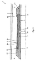
Fig. 1 shows a cross-sectional view along a longitudinal extension of anannular barrier 1 in its unexpanded condition. Theannular barrier 1 is rotationally symmetric around a centre axis of rotation. The annular barrier is to be expanded in anannulus 2 between a well tubular structure 3 and aninside wall 4 of aborehole 5 downhole.Fig. 2 shows the annular barrier ofFig. 1 In its expanded condition, providing zone isolation between a first zone and a second zone of theborehole 5. Theannular barrier 1 comprises atubular part 6 for mounting as part of the well tubular structure and anexpandable metal sleeve 7 surrounding thetubular part 6. The expandable metal sleeve has aninner face 7a facing the tubular part, and eachend connection part 12 which is connected with the tubular part, thereby defining aspace 13 between the inner face of theexpandable metal sleeve 7 and the tubular part. Thespace 13 is defined by the expandable metal sleeve, theconnection parts 12 and thetubular part 6. The annular barrier further comprises a firstsafety metal sleeve 8 surrounding the tubular part and abutting theexpandable metal sleeve 7. The first safety metal sleeve has a firstinner face 8a abutting anouter face 7b of the expandable metal sleeve, and eachend connection part 12 which is connected with the tubular part. Thetubular part 6 comprises anexpansion opening 11 for allowing fluid to enter thespace 13 during expansion of theannular barrier 1. The inner face of the firstsafety metal sleeve 8 abuts and contacts the face of the expandable metal sleeve along the whole length of the expandable metal sleeve in its unexpanded condition. In the expanded and unexpanded condition, theouter face 8b of the first safety metal sleeve abuts the inner wall of the borehole and during expansion, and the safety metal sleeve. limits the free movement of the expandable metal sleeve. Furthermore, the force applied to theexpandable metal sleeve 7 is transferred to thesafety metal sleeve 8 by means of the expandable metal sleeve, resulting in a more even distribution of the force applied on the safety metal sleeve than when applied on the expandable metal sleeve. -
Fig. 3 shows a cross-sectional view along a longitudinal extension of anannular barrier 1 condition further comprising a secondsafety metal sleeve 9 surrounding the tubular part, theexpandable metal sleeve 7 and the firstsafety metal sleeve 8. The secondsafety metal sleeve 9 has a secondInner face 9a facing the firstsafety metal sleeve 8, and eachend safety metal sleeve 9 is connected with theconnection part 12 which again is connected with the tubular part. Thetubular part 6 comprises anexpansion opening 11 for allowing fluid to enter thespace 13 during expansion of theannular barrier 1.Fig. 4 shows the annular barrier ofFig. 3 in its expanded condition, providing zone Isolation between a first zone and a second zone of theborehole 5. -
Fig. 5 shows an annular barrier further comprising an additionalsafety metal sleeve 10. Theannular barrier 1 shown inFig. 5 comprises one additionalsafety metal sleeve 10, the first and secondsafety metal sleeve expandable metal sleeve 7, but even more additional safety metal sleeves may be added to avoid ruptures of the annular barrier. - When using several additional safety metal sleeves such as shown in
Fig. 5 , the annular barrier may be optimised by using safety metal sleeves with different required expansion pressures, such that peripheral sleeves have lower required expansion pressures than more central sleeves. If the safety metal sleeves have lower required expansion pressures, e.g. because they are thinner than the expandable metal sleeve such as shown inFigs. 1 and2 , the pressure required to expand the annular barrier may be lowered. Instead of changing the thickness of the safety metal sleeves and the expandable metal sleeve, the sleeves may be made from different materials to provide a difference in required expansion pressure, e.g. one sleeve may be designed to require a smaller expansion pressure than another sleeve by using two different materials. Furthermore, the use of different materials may be used to provide a very ductile material in the outermost sleeves to inhibit necking in the outermost sleeves during expansion. On the other hand, the innermost sleeves, such as the expandable metal sleeve and the first safety metal sleeve, may be be made from a less ductile material, which may resist a larger external pressure from the outside of the annular barrier, e.g. sudden changes in the borehole pressure. Since the outermost sleeves are supported by the innermost sleeves when a pressure is applied from the outside, the ability of the innermost sleeves to resist such pressures is important when requiring an annular barrier with a high collapse pressure. - The thickness of the expandable metal sleeve shown in
Fig. 5 is substantially reduced compared to the expandable metal sleeves shown inFigs. 1-4 . When the number of safety metal sleeves is increased, the overall strength of the annular barrier is increased, and the thickness of theexpandable metal sleeve 7 may be decreased in order to reduce the total thickness of the sleeves. - An annular barrier may comprise several additional
safety metal sleeves 10, such as three additionalsafety metal sleeves 10, such as four additionalsafety metal sleeves 10, such as five additionalsafety metal sleeves 10, or even more additional safety metal sleeves. -
Figs. 6a-6c show a known annular barrier comprising anexpandable metal sleeve 7 with no safety metal sleeves. Theexpandable metal sleeve 7 has aweak area 17a, e.g. a thinning, an area with one or more fractures, an area with reduced strength due to material composition, an area with impurities. When the annular barrier having such a weak area is expanded, the expandable metal sleeve starts to deform more rapidly around theweak area 17a and bulge due to the reduced strength in this weak area, as shown inFig. 6b . The more rapid expansion of the material around the weak area leads to the creation of a "bubble" oh theexpandable metal sleeve 7 near the weak area. Since the material around the weak area expands more rapidly than the rest of the material of the expandable metal sleeve, the expandable metal sleeve thins in this area and is more likely to have afracture 20 near theweak area 17a, leading to at least a local rupture if not a circumferential rupture of the annular barrier as illustrated inFig. 6c . -
Figs. 7a-7c show an annular barrier comprising anexpandable metal sleeve 7 and a firstsafety metal sleeve 8. As shown inFig. 7a , theexpandable metal sleeve 7 has aweak area 17a, which is most likely to occur during the manufacturing process of making the expandable metal sleeve. Even though the first safety metal sleeve also has aweak area 17b, it is not likely to be arranged opposite the weak area of the expandable metal sleeve. When the annular barrier shown inFig. 7a is expanded as shown inFig. 7b , thesafety metal sleeve 8 braces and supports theweak area 17a of the expandable metal sleeve such that it cannot bulge and form a bubble, such as the one shown inFig. 6b . In this way, the safety metal sleeve prevents the expandable metal sleeve from moving freely but controls the expansion process of the expandable metal sleeve to occur more evenly. Furthermore, the force from the expansion fluid in thespace 13 will be applied on theinner face 7a of theexpandable metal sleeve 7, and since the safety metal sleeve abuts the expandable metal sleeve, the force on the safety metal sleeve will be applied by the expandable metal sleeve directly. Therefore, should thesafety metal sleeve 8 comprise aweak area 17b, the part of the expandable metal sleeve close to the weak area will brace theweak area 17b of the safety metal sleeve such that a bubble is not formed on the safety metal sleeve as well. The force on the safety metal sleeve is distributed evenly to the safety metal sleeve by means of the expandable metal sleeve, and thus no force will be applied to a part of the safety metal sleeve which is not in contact with the expandable metal sleeve until the expandable metal sleeve is once again in contact with that part of the safety metal sleeve. Thus, no bulging of the safety metal sleeve can occur as no force will be applied to the somewhat bulging part, resulting in a subsequent burst of the safety metal sleeve. - The safety metal sleeve of
Figs. 7a-7b is thinner than the expandable metal sleeve, e.g. the safety metal sleeve may be 0.5-1.0 mm and the expandable metal sleeve may be 5-10 mm and thus, by adding only a thin outer sleeve, the risk of fracturing the expandable metal sleeve during expansion is substantially reduced without substantially increasing the overall thickness of the annular barrier. -
Figs. 8a-8c show an annular barrier comprising anexpandable metal sleeve 7, a firstsafety metal sleeve 8 and a secondsafety metal sleeve 9. As shown inFig. 8a , theexpandable metal sleeve 7 has aweak area 17a, and the firstsafety metal sleeve 8 has aweak area 17b and the secondsafety metal sleeve 9 has aweak area 17c. Increasing the number of safety metal sleeves reduces the risk of all sleeves having a weak area close to each other. If all sleeves have a weak area close to each other, the situation resembles the situation shown inFig. 6a where only one sleeve comprising a weak area constitutes the expandable part of the annular barrier. Therefore, providing a safety metal sleeve substantially reduces the risk of rupturing the expandable metal sleeve during expansion, and the addition of more safety metal sleeves even further minimises this risk. Having an annular barrier, where theexpandable metal sleeve 7 has aweak area 17a close to or even spot on aweak area 17b on the first safety metal sleeve, the two inner sleeves, i.e. the expandable metal sleeve and the first safety metal sleeve, are still braced by the second safety metal sleeve to ensure that a "bubble" is not formed. Since the annular barrier has a large surface area and the weak areas of the sleeves with modem production techniques are typically very small and widely spread on this large surface area, the risk of two overlapping weak areas is very small. However, adding one more safety metal sleeves as shown inFigs. 8a-8c or even a third safety metal sleeve as shown inFig. 5 almost eliminates the risk of overlapping weak areas, since the probability may typically be lowered by several orders of magnitude for every additional safety metal sleeve. -
Fig. 9 shows a knownbarrier 400 comprising anexpandable sleeve member 40 surrounding atubular section 41 and a furtherouter sleeve member 42 partially surrounding theexpandable sleeve member 40 and enclosing a space 43 filled with a sealingmaterial 44 such as a polymeric material. This is a known solution thought to provide better sealing between theinside wall 4 of the borehole and an inside of theproduction casing 46. However, as shown InFig. 9 , If the expandable metal sleeve member comprises aweak area 45, the expandablemetal sleeve member 40 may still rupture during expansion, since a bubble or bulging may start to form within the space 43 and displace the polymeric material and eventually lead to a fracture in the sealing expandablemetal sleeve member 40. The collapse strength of the expandable metal sleeve member is thus substantially reduced. As the polymeric material leaves the space 43 through the opening in the further outer sleeve member, the barrier leaks since the pressurised fluid expanding the expandable metal sleeve member will force its way through the polymeric material and out through the opening, and a seal will never be formed. - The annular barrier of the present invention may be improved with respect to sealing properties towards the
inside wall 4 of the borehole by adding an additional sealing element surrounding an outermost saftey sleeve, which comprises an Intermediate layer of elastomer, rubber or polymer arranged between the outermost safety metal sleeve and a sealing element sleeve. Also, other known sealing elements may be added to the annular barrier surrounding the outermost saftey sleeve to improve sealing properties of the annular barrier. - Also, the outermost safety metal sleeve may be made from or comprise a sealing metal material. If additional sealing elements surrounding the outermost safety metal sleeve is inappropriate for other reasons such as limited space in the annulus, the outermost safety metal sleeve may be made from a material having good sealing properties such as high ductility.
- Also, the annular barrier may comprise restricting a free expansion of the sleeves.
- The
expandable metal sleeve 7 and the additionalsafety metal sleeves - Also, the metal used for the sleeves may have an elongation of 10-35%, preferably 25-35%. The metal may have a yield strength (cold worked) of 500-1000 MPa, preferably 500-700 MPa. The sleeves may be a cold-drawn or hot-drawn tubular structure.
- The thickness of the expandable metal sleeve may preferably be at least 10% greater than the thickness of the safety metal sleeves, and more preferably at least 15% greater than the thickness of the safety metal sleeves, and even more preferably at least 20% greater than the thickness of the safety metal sleeves.
- The thickness of the safety metal sleeve may be 0.5 mm to 5 mm, and the thickness of the expandable metal sleeve may be 5 mm to 20 mm.
- Furthermore, the safety metal sleeves may preferably be made from a material having an elongation of more than 10% of an elongation of the material of the expandable metal sleeve.
- The annular barrier may preferably comprise an expandable metal sleeve made from a material having a yield strength which is at least 10% higher than a yield strength of a material of the first and/or second safety metal sleeve, or more preferably at least 15% higher and even more preferably at least 20% higher than a yield strength of the material of the first and/or second safety metal sleeve.
- Also, the expandable metal sleeve may have an unexpanded outside diameter and an expanded outside diameter, the expanded diameter of the expandable metal sleeve being at least 10% larger than the unexpanded diameter, preferably at least 15% larger than the unexpanded diameter, and more preferably at least 30% larger than the unexpanded diameter.
- Although the invention has been described In the above in connection with preferred embodiments of the invention, it will be evident for a person skilled in the art that several modifications are conceivable without departing from the invention as defined by the following claims.
Claims (14)
- An annular barrier (1) to be expanded in an annulus (2) between a well tubular structure (3) and an inside wall (4) of a borehole (5) downhole for providing zone isolation between a first zone (200) and a second zone (300) of the borehole, comprising- a tubular part (6) for mounting as part of the well tubular structure,- an expandable metal sleeve (7) surrounding the tubular part and having an inner face (7a) facing the tubular part and an outer face (7b) facing towards the inside wall of the borehole, each end (71, 72) of the expandable metal sleeve being connected with a connection part (12) which is connected with the tubular part,- a space (13) between the inner face of the expandable metal sleeve and the tubular part,and- an expansion opening (11) in the tubular part (6) through which fluid may enter info the space (13) in order to expand the expandable metal sleeve (7),wherein the annular barrier further comprises a first safety metal sleeve (8) surrounding the tubular part and abutting the expandable metal sleeve characterised in that said first safety metal sleeve having a first face (8a) abutting the face of the expandable metal sleeve, each end (81, 82) of the first safety metal sleeve being connected with the connection part (12) which is connected with the tubular part.
- An annular barrier according to claim 1, wherein the first safety metal sleeve has a first inner face (8a) abutting the outer face of the expandable metal sleeve.
- An annular barrier according to claim 1 or 2, further comprising a second safety metal sleeve (9) surrounding the tubular part, said second safety metal sleeve having a second inner face (9a) facing the safety metal sleeve, each end (91, 92) of the second safety metal sleeve being connected with the connection part (12) which is connected with the tubular part.
- An annular barrier according to claim 3, further comprising a third safety metal sleeve (10), said third safety metal sleeve having a third inner face (10a) facing the second outer face (9b) of the second safety metal sleeve, each end (101, 102) of the third safety metal sleeve being connected with the connection part (12) which is connected with the tubular part.
- An annular barrier according to claim 1, further comprising a plurality of additional safety metal sleeves surrounding the tubular part and the first safety metal sleeve and being connected with the connection part (12) which is connected with the tubular part.
- An annular barrier according to any of the preceding claims, wherein the expandable metal sleeve and safety metal sleeve(s) have different required expansion pressures.
- An annular barrier according to any of the preceding claims, wherein the expandable metal sleeve and safety metal sleeve(s) are made from different materials.
- An annular barrier according to any of the preceding claims, wherein the sleeves have a thickness and the thickness of the expandable metal sleeve is greater than the thickness of the safety metal sleeve.
- An annular barrier according to any of the preceding claims, wherein the safety metal sleeve has a higher ductility than the expandable metal sleeve.
- An annular barrier according to any of the preceding claims, wherein the expandable metal sleeve has a higher yield strength than the safety metal sleeve.
- An annular barrier according to claim 9, wherein the first safety metal sleeve is made of a material having an elongation of more than 10% of an elongation of the material of the expandable metal sleeve.
- An annular barrier according to any of the preceding claims, wherein an additional sealing element surrounding an outermost saftey sleeve comprises an intermediate layer of elastomer, rubber or polymer arranged between the outermost safety metal sleeve and a sealing element sleeve.
- An annular barrier according to any of claims 3-5, wherein the safety metal sleeve closest to the inside wall (4) of the borehole is made from a sealing metal material.
- An annular barrier according to any of claims 3-5, wherein the safety metal sleeve closest to the inside wall (4) of the borehole comprises at least one sealing element.
Priority Applications (11)
| Application Number | Priority Date | Filing Date | Title |
|---|---|---|---|
| EP11181068.5A EP2570587B1 (en) | 2011-09-13 | 2011-09-13 | Annular barrier with safety metal sleeve |
| DK11181068.5T DK2570587T3 (en) | 2011-09-13 | 2011-09-13 | Ring-shaped barrier with safety metal pipe piece |
| CN201910537373.5A CN110242246A (en) | 2011-09-13 | 2012-09-12 | Annular barrier with safe metal sleeve |
| PCT/EP2012/067819 WO2013037816A1 (en) | 2011-09-13 | 2012-09-12 | Annular barrier with safety metal sleeve |
| MYPI2014000590A MY174721A (en) | 2011-09-13 | 2012-09-12 | Annular barrier with safety metal sleeve |
| MX2014002348A MX344574B (en) | 2011-09-13 | 2012-09-12 | Annular barrier with safety metal sleeve. |
| RU2014111784A RU2630339C2 (en) | 2011-09-13 | 2012-09-12 | Annular barrier with safety metal coupling |
| BR112013020172-0A BR112013020172B1 (en) | 2011-09-13 | 2012-09-12 | annular barrier to be expanded into an annular space between a tubular well structure and an inner wall of a well hole |
| CA2814336A CA2814336C (en) | 2011-09-13 | 2012-09-12 | Annular barrier with safety metal sleeve |
| CN201280041856.2A CN103764943A (en) | 2011-09-13 | 2012-09-12 | Annular barrier with safety metal sleeve |
| US13/878,609 US10844686B2 (en) | 2011-09-13 | 2012-09-12 | Annular barrier with safety metal sleeve |
Applications Claiming Priority (1)
| Application Number | Priority Date | Filing Date | Title |
|---|---|---|---|
| EP11181068.5A EP2570587B1 (en) | 2011-09-13 | 2011-09-13 | Annular barrier with safety metal sleeve |
Publications (2)
| Publication Number | Publication Date |
|---|---|
| EP2570587A1 EP2570587A1 (en) | 2013-03-20 |
| EP2570587B1 true EP2570587B1 (en) | 2013-10-30 |
Family
ID=46826556
Family Applications (1)
| Application Number | Title | Priority Date | Filing Date |
|---|---|---|---|
| EP11181068.5A Revoked EP2570587B1 (en) | 2011-09-13 | 2011-09-13 | Annular barrier with safety metal sleeve |
Country Status (10)
| Country | Link |
|---|---|
| US (1) | US10844686B2 (en) |
| EP (1) | EP2570587B1 (en) |
| CN (2) | CN110242246A (en) |
| BR (1) | BR112013020172B1 (en) |
| CA (1) | CA2814336C (en) |
| DK (1) | DK2570587T3 (en) |
| MX (1) | MX344574B (en) |
| MY (1) | MY174721A (en) |
| RU (1) | RU2630339C2 (en) |
| WO (1) | WO2013037816A1 (en) |
Families Citing this family (18)
| Publication number | Priority date | Publication date | Assignee | Title |
|---|---|---|---|---|
| US9267368B2 (en) * | 2013-04-29 | 2016-02-23 | Baker Hughes Incorporated | Fracturing multiple zones with inflatables |
| FR3012512A1 (en) | 2013-10-30 | 2015-05-01 | Saltel Ind | EXPANDABLE METAL SHIRT AND DEVICE USING THE SAME |
| US20160369603A1 (en) * | 2015-06-16 | 2016-12-22 | Welltec A/S | Redressing method and redressed completion system |
| CN105587287A (en) * | 2016-03-07 | 2016-05-18 | 威海丰泰新材料科技股份有限公司 | Expansion type packer |
| AU2018308919B2 (en) * | 2017-07-27 | 2021-05-27 | Welltec Oilfield Solutions Ag | Annular barrier for small diameter wells |
| GB2565778B (en) * | 2017-08-21 | 2019-12-04 | Morphpackers Ltd | Improved isolation barrier |
| GB2572449B (en) * | 2018-03-30 | 2020-09-16 | Morphpackers Ltd | Improved isolation barrier |
| EP3584403A1 (en) * | 2018-06-19 | 2019-12-25 | Welltec Oilfield Solutions AG | An annular barrier |
| EP3914803A1 (en) | 2019-01-23 | 2021-12-01 | Saltel Industries | Expandable metal packer system with pressure control device |
| US11802455B2 (en) * | 2019-01-23 | 2023-10-31 | Schlumberger Technology Corporation | Expandable metal packer with anchoring system |
| US11773681B2 (en) | 2019-09-14 | 2023-10-03 | Vertice Oil Tools Inc. | Methods and systems associated with developing a metal deformable packer |
| US10662734B1 (en) * | 2019-09-14 | 2020-05-26 | Vertice Oil Tools | Methods and systems for preventing hydrostatic head within a well |
| TWI739530B (en) * | 2020-07-27 | 2021-09-11 | 昶城有限公司 | Sealing device for telescopic pipe fitting |
| EP4015763A1 (en) * | 2020-12-18 | 2022-06-22 | Welltec Oilfield Solutions AG | Downhole completion system |
| EP4043691A1 (en) * | 2021-02-12 | 2022-08-17 | Welltec Oilfield Solutions AG | Annular barrier and downhole system |
| US11598472B2 (en) | 2021-04-15 | 2023-03-07 | Halliburton Energy Services, Inc. | Clamp on seal for water leaks |
| US11692411B2 (en) * | 2021-04-16 | 2023-07-04 | Welltec Oilfield Solutions Ag | Annular barrier and downhole system |
| CN114689128B (en) * | 2022-05-31 | 2022-08-19 | 青岛道万科技有限公司 | Special temperature and pressure measuring instrument and method thereof |
Citations (1)
| Publication number | Priority date | Publication date | Assignee | Title |
|---|---|---|---|---|
| US20060027371A1 (en) * | 2004-08-04 | 2006-02-09 | Read Well Services Limited | Apparatus and method |
Family Cites Families (22)
| Publication number | Priority date | Publication date | Assignee | Title |
|---|---|---|---|---|
| US2098484A (en) * | 1936-04-21 | 1937-11-09 | Brundred Oil Corp | Packer |
| US4967846A (en) * | 1984-04-04 | 1990-11-06 | Completion Tool Company | Progressively inflated packers |
| US4768590A (en) * | 1986-07-29 | 1988-09-06 | Tam International, Inc. | Inflatable well packer |
| GB9117683D0 (en) * | 1991-08-16 | 1991-10-02 | Head Philip F | Well packer |
| US5507345A (en) * | 1994-11-23 | 1996-04-16 | Chevron U.S.A. Inc. | Methods for sub-surface fluid shut-off |
| RU6406U1 (en) * | 1995-04-19 | 1998-04-16 | Клявин Рим Мусеевич | PACKING DEVICE |
| RU2128279C1 (en) | 1997-06-16 | 1999-03-27 | Закрытое акционерное общество "ЮКСОН" | Inflatable hydraulic packer |
| FR2791732B1 (en) * | 1999-03-29 | 2001-08-10 | Cooperation Miniere Et Ind Soc | BLOCKING DEVICE OF A WELLBORE |
| RU2224872C1 (en) * | 2002-07-29 | 2004-02-27 | Государственное унитарное предприятие Научно-производственное объединение "Гидротрубопровод" | Packer |
| GB0227206D0 (en) | 2002-11-21 | 2002-12-24 | Qinetiq Ltd | Electrical transmission system |
| RU2249669C1 (en) * | 2003-08-14 | 2005-04-10 | Общество с ограниченной ответственностью "ЛУКОЙЛ-ПЕРМЬ" | Two-packer device |
| US7234533B2 (en) * | 2003-10-03 | 2007-06-26 | Schlumberger Technology Corporation | Well packer having an energized sealing element and associated method |
| CN1624293A (en) * | 2003-12-04 | 2005-06-08 | 中国石油天然气股份有限公司 | Natural split-flow balancing squeeze in water-stop technology |
| US7347274B2 (en) | 2004-01-27 | 2008-03-25 | Schlumberger Technology Corporation | Annular barrier tool |
| US20060042801A1 (en) | 2004-08-24 | 2006-03-02 | Hackworth Matthew R | Isolation device and method |
| WO2008033115A1 (en) * | 2006-09-11 | 2008-03-20 | Halliburton Energy Services, Inc. | Swellable packer construction |
| CN101532600B (en) * | 2008-03-13 | 2013-03-13 | 中国石化集团胜利石油管理局钻井工艺研究院 | Method for leak stoppage of solid expansion pipe |
| US20090255691A1 (en) * | 2008-04-10 | 2009-10-15 | Baker Hughes Incorporated | Permanent packer using a slurry inflation medium |
| WO2009143461A2 (en) * | 2008-05-23 | 2009-11-26 | Halliburton Energy Services, Inc. | Downhole cable |
| EP2206879B1 (en) | 2009-01-12 | 2014-02-26 | Welltec A/S | Annular barrier and annular barrier system |
| EP2312119A1 (en) | 2009-10-07 | 2011-04-20 | Welltec A/S | An annular barrier |
| EP2706189B1 (en) | 2011-01-25 | 2017-10-18 | Welltec A/S | An annular barrier with a diaphragm |
-
2011
- 2011-09-13 EP EP11181068.5A patent/EP2570587B1/en not_active Revoked
- 2011-09-13 DK DK11181068.5T patent/DK2570587T3/en active
-
2012
- 2012-09-12 WO PCT/EP2012/067819 patent/WO2013037816A1/en active Application Filing
- 2012-09-12 MY MYPI2014000590A patent/MY174721A/en unknown
- 2012-09-12 US US13/878,609 patent/US10844686B2/en active Active
- 2012-09-12 BR BR112013020172-0A patent/BR112013020172B1/en not_active IP Right Cessation
- 2012-09-12 RU RU2014111784A patent/RU2630339C2/en active
- 2012-09-12 MX MX2014002348A patent/MX344574B/en active IP Right Grant
- 2012-09-12 CN CN201910537373.5A patent/CN110242246A/en active Pending
- 2012-09-12 CA CA2814336A patent/CA2814336C/en not_active Expired - Fee Related
- 2012-09-12 CN CN201280041856.2A patent/CN103764943A/en active Pending
Patent Citations (1)
| Publication number | Priority date | Publication date | Assignee | Title |
|---|---|---|---|---|
| US20060027371A1 (en) * | 2004-08-04 | 2006-02-09 | Read Well Services Limited | Apparatus and method |
Also Published As
| Publication number | Publication date |
|---|---|
| WO2013037816A1 (en) | 2013-03-21 |
| BR112013020172B1 (en) | 2020-11-03 |
| MX2014002348A (en) | 2014-04-14 |
| US20140196887A1 (en) | 2014-07-17 |
| EP2570587A1 (en) | 2013-03-20 |
| RU2630339C2 (en) | 2017-09-07 |
| US10844686B2 (en) | 2020-11-24 |
| DK2570587T3 (en) | 2013-11-11 |
| CN103764943A (en) | 2014-04-30 |
| CN110242246A (en) | 2019-09-17 |
| RU2014111784A (en) | 2015-10-20 |
| CA2814336A1 (en) | 2013-03-21 |
| BR112013020172A2 (en) | 2016-11-08 |
| CA2814336C (en) | 2014-08-12 |
| MY174721A (en) | 2020-05-10 |
| MX344574B (en) | 2016-12-20 |
Similar Documents
| Publication | Publication Date | Title |
|---|---|---|
| EP2570587B1 (en) | Annular barrier with safety metal sleeve | |
| US11473392B2 (en) | Downhole expandable metal tubular | |
| EP2246522B1 (en) | Improvements to swellable apparatus | |
| US9359860B2 (en) | Annular barrier | |
| US8997854B2 (en) | Swellable packer anchors | |
| US9217308B2 (en) | Active external casing packer (ECP) for frac operations in oil and gas wells | |
| US3542127A (en) | Reinforced inflatable packer with expansible back-up skirts for end portions | |
| CN102575508B (en) | Annular blocking device | |
| EP2538018A1 (en) | An annular barrier with external seal | |
| EP2706188B1 (en) | Annular barrier with a diaphragm | |
| US10151168B2 (en) | Downhole expandable tubular | |
| WO2010135644A2 (en) | High expansion metal seal system | |
| US20160348463A1 (en) | Annular barrier having a downhole expandable tubular | |
| WO2020104671A1 (en) | An annular barrier | |
| US20140014374A1 (en) | Swellable packer | |
| AU2013100364A4 (en) | Annular barrier with safety metal sleeve | |
| EP2625375B1 (en) | An annular barrier | |
| WO2015177546A1 (en) | Improved isolation barrier | |
| AU2013100388B4 (en) | Annular barrier |
Legal Events
| Date | Code | Title | Description |
|---|---|---|---|
| PUAI | Public reference made under article 153(3) epc to a published international application that has entered the european phase |
Free format text: ORIGINAL CODE: 0009012 |
|
| AK | Designated contracting states |
Kind code of ref document: A1 Designated state(s): AL AT BE BG CH CY CZ DE DK EE ES FI FR GB GR HR HU IE IS IT LI LT LU LV MC MK MT NL NO PL PT RO RS SE SI SK SM TR |
|
| AX | Request for extension of the european patent |
Extension state: BA ME |
|
| 17P | Request for examination filed |
Effective date: 20130327 |
|
| 17Q | First examination report despatched |
Effective date: 20130514 |
|
| GRAP | Despatch of communication of intention to grant a patent |
Free format text: ORIGINAL CODE: EPIDOSNIGR1 |
|
| GRAS | Grant fee paid |
Free format text: ORIGINAL CODE: EPIDOSNIGR3 |
|
| INTG | Intention to grant announced |
Effective date: 20130716 |
|
| GRAP | Despatch of communication of intention to grant a patent |
Free format text: ORIGINAL CODE: EPIDOSNIGR1 |
|
| GRAJ | Information related to disapproval of communication of intention to grant by the applicant or resumption of examination proceedings by the epo deleted |
Free format text: ORIGINAL CODE: EPIDOSDIGR1 |
|
| GRAS | Grant fee paid |
Free format text: ORIGINAL CODE: EPIDOSNIGR3 |
|
| INTG | Intention to grant announced |
Effective date: 20130816 |
|
| GRAP | Despatch of communication of intention to grant a patent |
Free format text: ORIGINAL CODE: EPIDOSNIGR1 |
|
| GRAA | (expected) grant |
Free format text: ORIGINAL CODE: 0009210 |
|
| STAA | Information on the status of an ep patent application or granted ep patent |
Free format text: STATUS: THE PATENT HAS BEEN GRANTED |
|
| TPAC | Observations filed by third parties |
Free format text: ORIGINAL CODE: EPIDOSNTIPA |
|
| INTG | Intention to grant announced |
Effective date: 20130917 |
|
| AK | Designated contracting states |
Kind code of ref document: B1 Designated state(s): AL AT BE BG CH CY CZ DE DK EE ES FI FR GB GR HR HU IE IS IT LI LT LU LV MC MK MT NL NO PL PT RO RS SE SI SK SM TR |
|
| REG | Reference to a national code |
Ref country code: GB Ref legal event code: FG4D |
|
| REG | Reference to a national code |
Ref country code: CH Ref legal event code: EP |
|
| REG | Reference to a national code |
Ref country code: NL Ref legal event code: T3 |
|
| REG | Reference to a national code |
Ref country code: DK Ref legal event code: T3 Effective date: 20131106 |
|
| REG | Reference to a national code |
Ref country code: AT Ref legal event code: REF Ref document number: 638549 Country of ref document: AT Kind code of ref document: T Effective date: 20131115 |
|
| REG | Reference to a national code |
Ref country code: IE Ref legal event code: FG4D |
|
| REG | Reference to a national code |
Ref country code: NO Ref legal event code: T2 Effective date: 20131030 |
|
| REG | Reference to a national code |
Ref country code: DE Ref legal event code: R096 Ref document number: 602011003548 Country of ref document: DE Effective date: 20131224 |
|
| REG | Reference to a national code |
Ref country code: AT Ref legal event code: MK05 Ref document number: 638549 Country of ref document: AT Kind code of ref document: T Effective date: 20131030 |
|
| REG | Reference to a national code |
Ref country code: LT Ref legal event code: MG4D |
|
| PG25 | Lapsed in a contracting state [announced via postgrant information from national office to epo] |
Ref country code: IS Free format text: LAPSE BECAUSE OF FAILURE TO SUBMIT A TRANSLATION OF THE DESCRIPTION OR TO PAY THE FEE WITHIN THE PRESCRIBED TIME-LIMIT Effective date: 20140228 Ref country code: HR Free format text: LAPSE BECAUSE OF FAILURE TO SUBMIT A TRANSLATION OF THE DESCRIPTION OR TO PAY THE FEE WITHIN THE PRESCRIBED TIME-LIMIT Effective date: 20131030 Ref country code: LT Free format text: LAPSE BECAUSE OF FAILURE TO SUBMIT A TRANSLATION OF THE DESCRIPTION OR TO PAY THE FEE WITHIN THE PRESCRIBED TIME-LIMIT Effective date: 20131030 Ref country code: SE Free format text: LAPSE BECAUSE OF FAILURE TO SUBMIT A TRANSLATION OF THE DESCRIPTION OR TO PAY THE FEE WITHIN THE PRESCRIBED TIME-LIMIT Effective date: 20131030 Ref country code: FI Free format text: LAPSE BECAUSE OF FAILURE TO SUBMIT A TRANSLATION OF THE DESCRIPTION OR TO PAY THE FEE WITHIN THE PRESCRIBED TIME-LIMIT Effective date: 20131030 Ref country code: BE Free format text: LAPSE BECAUSE OF FAILURE TO SUBMIT A TRANSLATION OF THE DESCRIPTION OR TO PAY THE FEE WITHIN THE PRESCRIBED TIME-LIMIT Effective date: 20131030 |
|
| PG25 | Lapsed in a contracting state [announced via postgrant information from national office to epo] |
Ref country code: LV Free format text: LAPSE BECAUSE OF FAILURE TO SUBMIT A TRANSLATION OF THE DESCRIPTION OR TO PAY THE FEE WITHIN THE PRESCRIBED TIME-LIMIT Effective date: 20131030 Ref country code: AT Free format text: LAPSE BECAUSE OF FAILURE TO SUBMIT A TRANSLATION OF THE DESCRIPTION OR TO PAY THE FEE WITHIN THE PRESCRIBED TIME-LIMIT Effective date: 20131030 Ref country code: RS Free format text: LAPSE BECAUSE OF FAILURE TO SUBMIT A TRANSLATION OF THE DESCRIPTION OR TO PAY THE FEE WITHIN THE PRESCRIBED TIME-LIMIT Effective date: 20131030 Ref country code: CY Free format text: LAPSE BECAUSE OF FAILURE TO SUBMIT A TRANSLATION OF THE DESCRIPTION OR TO PAY THE FEE WITHIN THE PRESCRIBED TIME-LIMIT Effective date: 20131030 Ref country code: ES Free format text: LAPSE BECAUSE OF FAILURE TO SUBMIT A TRANSLATION OF THE DESCRIPTION OR TO PAY THE FEE WITHIN THE PRESCRIBED TIME-LIMIT Effective date: 20131030 |
|
| PG25 | Lapsed in a contracting state [announced via postgrant information from national office to epo] |
Ref country code: PT Free format text: LAPSE BECAUSE OF FAILURE TO SUBMIT A TRANSLATION OF THE DESCRIPTION OR TO PAY THE FEE WITHIN THE PRESCRIBED TIME-LIMIT Effective date: 20140228 |
|
| REG | Reference to a national code |
Ref country code: DE Ref legal event code: R026 Ref document number: 602011003548 Country of ref document: DE |
|
| PLBI | Opposition filed |
Free format text: ORIGINAL CODE: 0009260 |
|
| PLAB | Opposition data, opponent's data or that of the opponent's representative modified |
Free format text: ORIGINAL CODE: 0009299OPPO |
|
| PG25 | Lapsed in a contracting state [announced via postgrant information from national office to epo] |
Ref country code: EE Free format text: LAPSE BECAUSE OF FAILURE TO SUBMIT A TRANSLATION OF THE DESCRIPTION OR TO PAY THE FEE WITHIN THE PRESCRIBED TIME-LIMIT Effective date: 20131030 |
|
| 26 | Opposition filed |
Opponent name: SALTEL INDUSTRIES Effective date: 20140710 |
|
| R26 | Opposition filed (corrected) |
Opponent name: SALTEL INDUSTRIES Effective date: 20140710 |
|
| PG25 | Lapsed in a contracting state [announced via postgrant information from national office to epo] |
Ref country code: PL Free format text: LAPSE BECAUSE OF FAILURE TO SUBMIT A TRANSLATION OF THE DESCRIPTION OR TO PAY THE FEE WITHIN THE PRESCRIBED TIME-LIMIT Effective date: 20131030 Ref country code: CZ Free format text: LAPSE BECAUSE OF FAILURE TO SUBMIT A TRANSLATION OF THE DESCRIPTION OR TO PAY THE FEE WITHIN THE PRESCRIBED TIME-LIMIT Effective date: 20131030 Ref country code: SK Free format text: LAPSE BECAUSE OF FAILURE TO SUBMIT A TRANSLATION OF THE DESCRIPTION OR TO PAY THE FEE WITHIN THE PRESCRIBED TIME-LIMIT Effective date: 20131030 Ref country code: IT Free format text: LAPSE BECAUSE OF FAILURE TO SUBMIT A TRANSLATION OF THE DESCRIPTION OR TO PAY THE FEE WITHIN THE PRESCRIBED TIME-LIMIT Effective date: 20131030 Ref country code: RO Free format text: LAPSE BECAUSE OF FAILURE TO SUBMIT A TRANSLATION OF THE DESCRIPTION OR TO PAY THE FEE WITHIN THE PRESCRIBED TIME-LIMIT Effective date: 20131030 |
|
| PLAX | Notice of opposition and request to file observation + time limit sent |
Free format text: ORIGINAL CODE: EPIDOSNOBS2 |
|
| REG | Reference to a national code |
Ref country code: DE Ref legal event code: R026 Ref document number: 602011003548 Country of ref document: DE Effective date: 20140710 |
|
| PLBB | Reply of patent proprietor to notice(s) of opposition received |
Free format text: ORIGINAL CODE: EPIDOSNOBS3 |
|
| PG25 | Lapsed in a contracting state [announced via postgrant information from national office to epo] |
Ref country code: SI Free format text: LAPSE BECAUSE OF FAILURE TO SUBMIT A TRANSLATION OF THE DESCRIPTION OR TO PAY THE FEE WITHIN THE PRESCRIBED TIME-LIMIT Effective date: 20131030 |
|
| PG25 | Lapsed in a contracting state [announced via postgrant information from national office to epo] |
Ref country code: LU Free format text: LAPSE BECAUSE OF FAILURE TO SUBMIT A TRANSLATION OF THE DESCRIPTION OR TO PAY THE FEE WITHIN THE PRESCRIBED TIME-LIMIT Effective date: 20140913 Ref country code: MC Free format text: LAPSE BECAUSE OF FAILURE TO SUBMIT A TRANSLATION OF THE DESCRIPTION OR TO PAY THE FEE WITHIN THE PRESCRIBED TIME-LIMIT Effective date: 20131030 |
|
| REG | Reference to a national code |
Ref country code: CH Ref legal event code: PL |
|
| REG | Reference to a national code |
Ref country code: IE Ref legal event code: MM4A |
|
| PG25 | Lapsed in a contracting state [announced via postgrant information from national office to epo] |
Ref country code: CH Free format text: LAPSE BECAUSE OF NON-PAYMENT OF DUE FEES Effective date: 20140930 Ref country code: LI Free format text: LAPSE BECAUSE OF NON-PAYMENT OF DUE FEES Effective date: 20140930 |
|
| PG25 | Lapsed in a contracting state [announced via postgrant information from national office to epo] |
Ref country code: IE Free format text: LAPSE BECAUSE OF NON-PAYMENT OF DUE FEES Effective date: 20140913 |
|
| PG25 | Lapsed in a contracting state [announced via postgrant information from national office to epo] |
Ref country code: SM Free format text: LAPSE BECAUSE OF FAILURE TO SUBMIT A TRANSLATION OF THE DESCRIPTION OR TO PAY THE FEE WITHIN THE PRESCRIBED TIME-LIMIT Effective date: 20131030 |
|
| PG25 | Lapsed in a contracting state [announced via postgrant information from national office to epo] |
Ref country code: MT Free format text: LAPSE BECAUSE OF FAILURE TO SUBMIT A TRANSLATION OF THE DESCRIPTION OR TO PAY THE FEE WITHIN THE PRESCRIBED TIME-LIMIT Effective date: 20131030 Ref country code: BG Free format text: LAPSE BECAUSE OF FAILURE TO SUBMIT A TRANSLATION OF THE DESCRIPTION OR TO PAY THE FEE WITHIN THE PRESCRIBED TIME-LIMIT Effective date: 20131030 Ref country code: GR Free format text: LAPSE BECAUSE OF FAILURE TO SUBMIT A TRANSLATION OF THE DESCRIPTION OR TO PAY THE FEE WITHIN THE PRESCRIBED TIME-LIMIT Effective date: 20140131 |
|
| PG25 | Lapsed in a contracting state [announced via postgrant information from national office to epo] |
Ref country code: HU Free format text: LAPSE BECAUSE OF FAILURE TO SUBMIT A TRANSLATION OF THE DESCRIPTION OR TO PAY THE FEE WITHIN THE PRESCRIBED TIME-LIMIT; INVALID AB INITIO Effective date: 20110913 Ref country code: TR Free format text: LAPSE BECAUSE OF FAILURE TO SUBMIT A TRANSLATION OF THE DESCRIPTION OR TO PAY THE FEE WITHIN THE PRESCRIBED TIME-LIMIT Effective date: 20131030 |
|
| REG | Reference to a national code |
Ref country code: FR Ref legal event code: PLFP Year of fee payment: 6 |
|
| APAH | Appeal reference modified |
Free format text: ORIGINAL CODE: EPIDOSCREFNO |
|
| APBM | Appeal reference recorded |
Free format text: ORIGINAL CODE: EPIDOSNREFNO |
|
| APBP | Date of receipt of notice of appeal recorded |
Free format text: ORIGINAL CODE: EPIDOSNNOA2O |
|
| REG | Reference to a national code |
Ref country code: FR Ref legal event code: PLFP Year of fee payment: 7 |
|
| APBQ | Date of receipt of statement of grounds of appeal recorded |
Free format text: ORIGINAL CODE: EPIDOSNNOA3O |
|
| PG25 | Lapsed in a contracting state [announced via postgrant information from national office to epo] |
Ref country code: MK Free format text: LAPSE BECAUSE OF FAILURE TO SUBMIT A TRANSLATION OF THE DESCRIPTION OR TO PAY THE FEE WITHIN THE PRESCRIBED TIME-LIMIT Effective date: 20131030 |
|
| REG | Reference to a national code |
Ref country code: FR Ref legal event code: PLFP Year of fee payment: 8 |
|
| PG25 | Lapsed in a contracting state [announced via postgrant information from national office to epo] |
Ref country code: AL Free format text: LAPSE BECAUSE OF FAILURE TO SUBMIT A TRANSLATION OF THE DESCRIPTION OR TO PAY THE FEE WITHIN THE PRESCRIBED TIME-LIMIT Effective date: 20131030 |
|
| RAP2 | Party data changed (patent owner data changed or rights of a patent transferred) |
Owner name: WELLTEC OILFIELD SOLUTIONS AG |
|
| REG | Reference to a national code |
Ref country code: DE Ref legal event code: R082 Ref document number: 602011003548 Country of ref document: DE Representative=s name: SAMSON & PARTNER PATENTANWAELTE MBB, DE Ref country code: DE Ref legal event code: R081 Ref document number: 602011003548 Country of ref document: DE Owner name: WELLTEC OILFIELD SOLUTIONS AG, CH Free format text: FORMER OWNER: WELLTEC A/S, ALLEROED, DK |
|
| REG | Reference to a national code |
Ref country code: NO Ref legal event code: CHAD Owner name: WELLTEC OILFIELD SOLUTIONS AG, CH Ref country code: NO Ref legal event code: CREP Representative=s name: ACAPO AS, POSTBOKS 1880 NORDNES, 5817 BERGEN |
|
| REG | Reference to a national code |
Ref country code: GB Ref legal event code: 732E Free format text: REGISTERED BETWEEN 20190429 AND 20190502 |
|
| REG | Reference to a national code |
Ref country code: NL Ref legal event code: PD Owner name: WELLTEC OILFIELD SOLUTIONS AG; CH Free format text: DETAILS ASSIGNMENT: CHANGE OF OWNER(S), ASSIGNMENT; FORMER OWNER NAME: WELLTEC A/S Effective date: 20190607 |
|
| RAP2 | Party data changed (patent owner data changed or rights of a patent transferred) |
Owner name: WELLTEC OILFIELD SOLUTIONS AG |
|
| APBY | Invitation to file observations in appeal sent |
Free format text: ORIGINAL CODE: EPIDOSNOBA2O |
|
| APBU | Appeal procedure closed |
Free format text: ORIGINAL CODE: EPIDOSNNOA9O |
|
| APCA | Receipt of observations in appeal recorded |
Free format text: ORIGINAL CODE: EPIDOSNOBA4O |
|
| PGFP | Annual fee paid to national office [announced via postgrant information from national office to epo] |
Ref country code: FR Payment date: 20200918 Year of fee payment: 10 Ref country code: NO Payment date: 20200923 Year of fee payment: 10 Ref country code: DK Payment date: 20200916 Year of fee payment: 10 Ref country code: GB Payment date: 20200921 Year of fee payment: 10 Ref country code: NL Payment date: 20200921 Year of fee payment: 10 Ref country code: DE Payment date: 20200922 Year of fee payment: 10 |
|
| RDAF | Communication despatched that patent is revoked |
Free format text: ORIGINAL CODE: EPIDOSNREV1 |
|
| STAA | Information on the status of an ep patent application or granted ep patent |
Free format text: STATUS: THE PATENT HAS BEEN GRANTED |
|
| REG | Reference to a national code |
Ref country code: DE Ref legal event code: R103 Ref document number: 602011003548 Country of ref document: DE Ref country code: DE Ref legal event code: R064 Ref document number: 602011003548 Country of ref document: DE |
|
| RDAG | Patent revoked |
Free format text: ORIGINAL CODE: 0009271 |
|
| STAA | Information on the status of an ep patent application or granted ep patent |
Free format text: STATUS: PATENT REVOKED |
|
| REG | Reference to a national code |
Ref country code: FI Ref legal event code: MGE |
|
| 27W | Patent revoked |
Effective date: 20210722 |
|
| GBPR | Gb: patent revoked under art. 102 of the ep convention designating the uk as contracting state |
Effective date: 20210722 |