EP2570551A2 - A cassette of a floating bridge - Google Patents
A cassette of a floating bridge Download PDFInfo
- Publication number
- EP2570551A2 EP2570551A2 EP12171708A EP12171708A EP2570551A2 EP 2570551 A2 EP2570551 A2 EP 2570551A2 EP 12171708 A EP12171708 A EP 12171708A EP 12171708 A EP12171708 A EP 12171708A EP 2570551 A2 EP2570551 A2 EP 2570551A2
- Authority
- EP
- European Patent Office
- Prior art keywords
- cassette
- coupling
- flat
- socket
- same type
- Prior art date
- Legal status (The legal status is an assumption and is not a legal conclusion. Google has not performed a legal analysis and makes no representation as to the accuracy of the status listed.)
- Granted
Links
Images



Classifications
-
- E—FIXED CONSTRUCTIONS
- E01—CONSTRUCTION OF ROADS, RAILWAYS, OR BRIDGES
- E01D—CONSTRUCTION OF BRIDGES, ELEVATED ROADWAYS OR VIADUCTS; ASSEMBLY OF BRIDGES
- E01D15/00—Movable or portable bridges; Floating bridges
- E01D15/14—Floating bridges, e.g. pontoon bridges
- E01D15/20—Floating bridges, e.g. pontoon bridges collapsible, expandable, inflatable or the like with main load supporting structure consisting only of non-rigid members
Definitions
- the present invention relates to floating bridges comprising individual cassettes of the type that have a fixed portion for accommodating an inflatable pontoon and a movable portion being movable upon expansion of the pontoon.
- Typical cassettes for floating bridges have a fixed configuration, resulting in large dimensions which make them difficult to be transported and assembled.
- the fixed configuration allows to use locking arrangements distributed along a relatively large coupling area between the cassettes, which may be hard to assemble, but provide adequate coupling.
- the typical cassette of a floating bridge has a fixed configuration and constant displacement.
- the object of the invention is a cassette of a floating bridge, the cassette comprising a fixed portion for accommodating an inflatable pontoon and a movable portion being movable upon expansion of the inflatable pontoon, wherein the cassette comprises a locking arrangement for coupling the cassette with other cassettes of the same type by coupling edges to form a floating bridge with side edges.
- the locking arrangement comprises a set of elements mounted at the fixed portion of the cassette and comprising a plurality of main locks positioned at the coupling edges of the cassette, each comprising a socket positioned at one coupling edge for receiving a flat bolt having a tapered end and configured to be slidably extensible from the opposite coupling edge of another cassette of the same type, a pair of side locks positioned at the side edges of the cassette, each comprising a first side socket near one of the coupling edges and configured to receive a head of a pivotable arm being mounted near the opposite coupling edge of another cassette of the same type.
- the main locks comprise at least two vertical flat bolts arranged at the side walls.
- the main locks comprise at least two horizontal flat bolts arranged along and below the edge of the road surface of the cassette.
- the flat bolts have a pair of openings configured to receive a pin to fix the position of the flat bolt in a contracted position, wherein the flat bolt is substantially hidden in the cassette and in an extended position, wherein the flat bolt is extended from the cassette to enable coupling with another cassette of the same type.
- the flat bolts are arranged in the sockets, both having a length equal to the width of the cassette, such that when the flat bolt is extended from the socket it enables the portion of the socket to receive the flat bolt of another cassette of the same type.
- the flat bolts have handles to enable manual sliding of the flat bolts.
- the cassette further comprises a second side socket configured to receive the head of the pivotable arm when the cassette is not coupled with another cassette.
- the first side socket further comprises means to block the head from exiting the socket.
- the movable portion comprises a bottom plate mounted to the fixed portion via telescopic arms, each telescopic arm comprising a spring configured to be stretched upon inflation of the inflatable pontoon and its extension beyond the fixed portion.
- the cassette further comprises a pivotable plate mounted via a hinge to the side edge of the cassette and supported by rollers on the bottom plate.
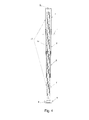
- the main elements of the cassette according to the invention are shown in Fig. 1 .
- the cassette comprises a fixed portion 21 for accommodating an inflatable pontoon (not shown in the drawing) and a movable portion 22 being movable upon expansion of the inflatable pontoon.
- a road surface is formed on top of the fixed portion 21.
- the cassette is intended to be coupled with other cassettes of the same type by coupling edges 31, 32 to form a floating bridge with side edges.
- the pontoon is preferably made of highly durable and highly resistant material.
- the pontoon is preferably inflatable by compressed air.
- the locking arrangement for coupling the cassettes comprises elements, which are all mounted at the fixed portion 21 of the cassette.
- That mechanical locking arrangement comprises main locks and side locks, which will be described in details below.
- the main locks are intended to mainly carry the load of the bridge.
- the main locks of the embodiment shown in Fig. 1 comprise two vertical flat bolts 1, arranged at the side walls 33, and two horizontal flat bolts 2, arranged along and below the edge of the road surface, that extend from one coupling edge 32 of the cassette.
- At the opposite edge 31 of the cassette there are formed corresponding sockets 4, 5 to accommodate the flat bolts 1, 2 of another cassette of the same type.
- the flat bolts 1, 2 have tapered ends to facilitate insertion of the bolts 1, 2 to the sockets 4, 5.
- the flat bolts 1, 2 are slidably extensible from the coupling edge 32. The manual manipulation, i.e. sliding in and out, of the flat bolts 1, 2 is facilitated by handles 6.
- the flat bolts may be positioned in a contracted position, when they are substantially hidden inside the body of the cassette, to optimize the cassette size for transportation.
- the flat bolts may be positioned in an extended position, as shown in Fig. 1 , when they are partially extended outside the body of the cassette, to enable coupling with another cassette.
- the length of the flat bolt 1, 2 which remains inside the cassette is at least equal to the length of the flat bolt 1, 2 extended outside the cassette.
- the flat bolts 1, 2 may have a length equal substantially to the width of the cassette and they are positioned slidably inside the sockets 4, 5, which also have the width of the cassette.
- the flat bolt 1, 2 when the flat bolt 1, 2 is extended from the socket 4, 5, it frees a portion of the socket and enables that portion to receive the extended portion of the flat bolt 1, 2 of another cassette of the same type.
- Such whole-width bolts and sockets may form part of the load-bearing structure of the cassette.
- the flat bolts 1, 2 may have a pair of openings 8A, 8B configured to receive a pin 7 to fix the position of the flat bolt 1, 2 in the extended position and in the contracted position. If the bolt is positioned in the socket 4, 5, then the socket also has an opening 8C to enable insertion of the pin 7 to the openings 8A, 8B of the flat bolt 1, 2.
- the side locks shown in details in Fig. 3A and 3B in an open and closed configuration, respectively, are intended to mainly hold the cassettes together and define the play between the cassettes.
- the cassette comprises one side lock at each side 31.
- the side lock comprises a pivotable arm 3, preferably rotatable by 180°, mounted at the side walls 33 near one of the coupling edges 32.
- the arm 3 can be rotated such that it extends beyond the coupling edge 32 to fit into a first side socket 10 near the opposite coupling edge 31 of another cassette of the same type, when the flat bolts 1, 2 are inserted to sockets 4, 5 and the coupling edges 31, 32 of the cassettes are brought adjacently together.
- the head 9 at the end of the arm has a trapezoid shape and the first side socket 10 has a slightly larger trapezoid shape, so that some play exists between the head 9 and the socket 10, so as to enable some relative movement between the cassettes.
- the first side socket 10 has means 11 to block the head 9 from exiting the socket 10, such as a slidable pin that has to be opened to enable insertion of the head 9 and closed to enable blocking of the head in the closed configuration. In the open configuration, when the cassettes are not coupled, the head 9 may rest in a second side socket 12 to be protected from accidental damage during transport.
- the movable portion 22 of the cassette comprises a mechanism for opening the cassette, which comprises a profiled bottom plate 15 mounted to the fixed portion 21 via telescopic arms 13, shown in a cross-section on fig. 4 .
- Each telescopic arm 13 comprises a spring 14 configured to be stretched upon inflation of the inflatable pontoon and its extension beyond the fixed portion, as in the transport configuration and before deployment, the pontoon is compressed in the fixed part chamber below the road surface.
- the telescopic arms 13 comprise four coaxial cylinders c, d, e, f of decreasing diameters and separated by centering rings.
- the spring 14 is mounted coaxially with the cylinders and attached to the terminal cylinders via fasteners g.
- the springs 14 force the telescopic arms 13 to contract and therefore move the bottom plate 15 upwards, to close the cassette and fold the pontoon back into the chamber in the fixed portion of the cassette, as shown in Fig. 6 .
- the cassette may further comprise a pivotable protective plate 16 mounted via one or more hinges 17 to the side edge 33 of the cassette.
- the protective plate 16 is supported by rollers 18 on the bottom plate 15. When the bottom plate 15 moves downwards, the pivotable protective plate 16 moves by rollers 18 along the bottom plate.
- the pivotable protective plate 16 protects the pontoon and the internal mechanisms of the cassette.
- the plate 16 may be mounted at one or both side edges 33 of the cassette.
- the cassette according to the invention has a number of advantages.
- the tapered-end flat bolts allow easy connection of the cassettes when assembled on water and can carry high bending forces of the load when the cassettes are assembled into a floating bridge.
- the side locks protect the cassettes from decoupling,, even under strong water current, and define appropriate distance and play between cassettes.
- the movable portion of the cassette provides support and protection for the inflatable pontoon. It enables automatic folding of the pontoon inside the chamber of the fixed portion of the cassette upon deflation of the pontoon.
- the pivotable protecting plate protects the pontoons and other elements of the floating bridge along its side edges. It also reduces the pressure of water to the side edge of the bridge.
- the mechanisms employed have a simple construction and therefore allow for a low cost of production of the cassette.
- the cassettes can be reused in different exploitation fields.
- the cassette has a compact construction and can be easily transported on limited cargo space.
- the cassettes can be used to form a fully functional floating object by a small crew of personnel without any special training, which reduces the cost of exploitation of the system.
Landscapes
- Engineering & Computer Science (AREA)
- Architecture (AREA)
- Civil Engineering (AREA)
- Structural Engineering (AREA)
- Bridges Or Land Bridges (AREA)
- Automatic Tape Cassette Changers (AREA)
- Magnetic Resonance Imaging Apparatus (AREA)
Abstract
Description
- The present invention relates to floating bridges comprising individual cassettes of the type that have a fixed portion for accommodating an inflatable pontoon and a movable portion being movable upon expansion of the pontoon.
- Typical cassettes for floating bridges have a fixed configuration, resulting in large dimensions which make them difficult to be transported and assembled. However, the fixed configuration allows to use locking arrangements distributed along a relatively large coupling area between the cassettes, which may be hard to assemble, but provide adequate coupling.
- Coupling of individual cassettes should provide durability and allow for a relative limited movement between the modules. This issue has been addressed by the following patent publications:
PL158579B2 PL297453B2 - The typical cassette of a floating bridge has a fixed configuration and constant displacement. There are known pontoon systems with additional air-inflatable pontoons, but they have a fixed configuration as well.
- There are also know, but currently much less popular, floating bridge cassettes of a regulated displacement and variable configuration. For example, a cassette described in
EP2251255 has a two-part split bottom which opens upon extension of the inflatable pontoon. Cassettes of this type are much easier to be transported and assembled due to small dimensions in their contracted, transport configuration. However, the locking arrangements for coupling the cassettes of the fixed, bulky type, are not applicable to the variable configuration cassettes. The locking arrangements used in variable configuration cassettes so far do not provide the expected durability and ease of assembly. - There is therefore a need to provide a locking arrangement to couple cassettes of a variable configuration which will be durable and which will facilitate assembly of the cassettes into a floating bridge.
- The object of the invention is a cassette of a floating bridge, the cassette comprising a fixed portion for accommodating an inflatable pontoon and a movable portion being movable upon expansion of the inflatable pontoon, wherein the cassette comprises a locking arrangement for coupling the cassette with other cassettes of the same type by coupling edges to form a floating bridge with side edges. The locking arrangement comprises a set of elements mounted at the fixed portion of the cassette and comprising a plurality of main locks positioned at the coupling edges of the cassette, each comprising a socket positioned at one coupling edge for receiving a flat bolt having a tapered end and configured to be slidably extensible from the opposite coupling edge of another cassette of the same type, a pair of side locks positioned at the side edges of the cassette, each comprising a first side socket near one of the coupling edges and configured to receive a head of a pivotable arm being mounted near the opposite coupling edge of another cassette of the same type.
- Preferably, the main locks comprise at least two vertical flat bolts arranged at the side walls.
- Preferably, the main locks comprise at least two horizontal flat bolts arranged along and below the edge of the road surface of the cassette.
- Preferably, the flat bolts have a pair of openings configured to receive a pin to fix the position of the flat bolt in a contracted position, wherein the flat bolt is substantially hidden in the cassette and in an extended position, wherein the flat bolt is extended from the cassette to enable coupling with another cassette of the same type.
- Preferably, the flat bolts are arranged in the sockets, both having a length equal to the width of the cassette, such that when the flat bolt is extended from the socket it enables the portion of the socket to receive the flat bolt of another cassette of the same type.
- Preferably, the flat bolts have handles to enable manual sliding of the flat bolts.
- Preferably, the cassette further comprises a second side socket configured to receive the head of the pivotable arm when the cassette is not coupled with another cassette.
- Preferably, the first side socket further comprises means to block the head from exiting the socket.
- Preferably, the movable portion comprises a bottom plate mounted to the fixed portion via telescopic arms, each telescopic arm comprising a spring configured to be stretched upon inflation of the inflatable pontoon and its extension beyond the fixed portion.
- Preferably, the cassette further comprises a pivotable plate mounted via a hinge to the side edge of the cassette and supported by rollers on the bottom plate.
- The object of the invention is shown by means of exemplary embodiments on a drawing, in which:
-
Fig. 1 shows the main elements of the cassette in an open configuration, -
Fig. 2 shows the details of a bolt and a socket of the main lock. -
Figs. 3A and 3B show the details of the side lock. -
Fig. 4 shows a cross-section of a telescopic arm. -
Fig. 5 shows details of a pivotable plate. -
Fig. 6 shows the main elements of the cassette in a closed configuration. - The main elements of the cassette according to the invention are shown in
Fig. 1 . The cassette comprises afixed portion 21 for accommodating an inflatable pontoon (not shown in the drawing) and a movable portion 22 being movable upon expansion of the inflatable pontoon. A road surface is formed on top of the fixedportion 21. The cassette is intended to be coupled with other cassettes of the same type bycoupling edges - The locking arrangement for coupling the cassettes comprises elements, which are all mounted at the
fixed portion 21 of the cassette. That mechanical locking arrangement comprises main locks and side locks, which will be described in details below. - The main locks are intended to mainly carry the load of the bridge. The main locks of the embodiment shown in
Fig. 1 comprise two verticalflat bolts 1, arranged at theside walls 33, and two horizontalflat bolts 2, arranged along and below the edge of the road surface, that extend from onecoupling edge 32 of the cassette. At theopposite edge 31 of the cassette there are formedcorresponding sockets flat bolts flat bolts bolts sockets flat bolts coupling edge 32. The manual manipulation, i.e. sliding in and out, of theflat bolts handles 6. The flat bolts may be positioned in a contracted position, when they are substantially hidden inside the body of the cassette, to optimize the cassette size for transportation. The flat bolts may be positioned in an extended position, as shown inFig. 1 , when they are partially extended outside the body of the cassette, to enable coupling with another cassette. Preferably, in the extended position, the length of theflat bolt flat bolt flat bolts sockets flat bolt socket flat bolt Fig. 2 , theflat bolts openings pin 7 to fix the position of theflat bolt socket pin 7 to theopenings flat bolt - The side locks, shown in details in
Fig. 3A and 3B in an open and closed configuration, respectively, are intended to mainly hold the cassettes together and define the play between the cassettes. As shown inFig. 1 , the cassette comprises one side lock at eachside 31. The side lock comprises apivotable arm 3, preferably rotatable by 180°, mounted at theside walls 33 near one of thecoupling edges 32. Thearm 3 can be rotated such that it extends beyond thecoupling edge 32 to fit into afirst side socket 10 near theopposite coupling edge 31 of another cassette of the same type, when theflat bolts sockets coupling edges head 9 at the end of the arm has a trapezoid shape and thefirst side socket 10 has a slightly larger trapezoid shape, so that some play exists between thehead 9 and thesocket 10, so as to enable some relative movement between the cassettes. Thefirst side socket 10 has means 11 to block thehead 9 from exiting thesocket 10, such as a slidable pin that has to be opened to enable insertion of thehead 9 and closed to enable blocking of the head in the closed configuration. In the open configuration, when the cassettes are not coupled, thehead 9 may rest in asecond side socket 12 to be protected from accidental damage during transport. - The movable portion 22 of the cassette comprises a mechanism for opening the cassette, which comprises a profiled
bottom plate 15 mounted to the fixedportion 21 viatelescopic arms 13, shown in a cross-section onfig. 4 . Eachtelescopic arm 13 comprises aspring 14 configured to be stretched upon inflation of the inflatable pontoon and its extension beyond the fixed portion, as in the transport configuration and before deployment, the pontoon is compressed in the fixed part chamber below the road surface. Thetelescopic arms 13 comprise four coaxial cylinders c, d, e, f of decreasing diameters and separated by centering rings. Thespring 14 is mounted coaxially with the cylinders and attached to the terminal cylinders via fasteners g. When air is deflated from the pontoon, thesprings 14 force thetelescopic arms 13 to contract and therefore move thebottom plate 15 upwards, to close the cassette and fold the pontoon back into the chamber in the fixed portion of the cassette, as shown inFig. 6 . - The cassette may further comprise a pivotable
protective plate 16 mounted via one or more hinges 17 to theside edge 33 of the cassette. Theprotective plate 16 is supported by rollers 18 on thebottom plate 15. When thebottom plate 15 moves downwards, the pivotableprotective plate 16 moves by rollers 18 along the bottom plate. The pivotableprotective plate 16 protects the pontoon and the internal mechanisms of the cassette. Theplate 16 may be mounted at one or both side edges 33 of the cassette. - The cassette according to the invention has a number of advantages. The tapered-end flat bolts allow easy connection of the cassettes when assembled on water and can carry high bending forces of the load when the cassettes are assembled into a floating bridge. The side locks protect the cassettes from decoupling,, even under strong water current, and define appropriate distance and play between cassettes. The movable portion of the cassette provides support and protection for the inflatable pontoon. It enables automatic folding of the pontoon inside the chamber of the fixed portion of the cassette upon deflation of the pontoon. The pivotable protecting plate protects the pontoons and other elements of the floating bridge along its side edges. It also reduces the pressure of water to the side edge of the bridge.
- The mechanisms employed have a simple construction and therefore allow for a low cost of production of the cassette. The cassettes can be reused in different exploitation fields. The cassette has a compact construction and can be easily transported on limited cargo space. The cassettes can be used to form a fully functional floating object by a small crew of personnel without any special training, which reduces the cost of exploitation of the system.
Claims (10)
- A cassette of a floating bridge, the cassette comprising a fixed portion (21) for accommodating an inflatable pontoon and a movable portion (22) being movable upon expansion of the inflatable pontoon, wherein the cassette comprises a locking arrangement for coupling the cassette with other cassettes of the same type by coupling edges (31, 32) to form a floating bridge with side edges (33), characterized in that the locking arrangement comprises a set of elements mounted at the fixed portion (21) of the cassette and comprising:- a plurality of main locks positioned at the coupling edges (31, 32) of the cassette, each comprising a socket (4, 5) positioned at one coupling edge (31) for receiving a flat bolt (1, 2) having a tapered end and configured to be slidably extensible from the opposite coupling edge (32) of another cassette of the same type,- a pair of side locks positioned at the side edges (33) of the cassette, each comprising a first side socket (10) near one of the coupling edges (31) and configured to receive a head (9) of a pivotable arm (3) being mounted near the opposite coupling edge (32) of another cassette of the same type.
- The cassette according to claim 1, wherein the main locks comprise at least two vertical flat bolts (1) arranged at the side walls.
- The cassette according to any of previous claims, wherein the main locks comprise at least two horizontal flat bolts (2) arranged along and below the edge of the road surface of the cassette.
- The cassette according to any of previous claims, wherein the flat bolts (1, 2) have a pair of openings (8A, 8B) configured to receive a pin (7) to fix the position of the flat bolt (1, 2) in a contracted position, wherein the flat bolt (1, 2) is substantially hidden in the cassette and in an extended position, wherein the flat bolt (1, 2) is extended from the cassette to enable coupling with another cassette of the same type.
- The cassette according to any of previous claims, wherein the flat bolts (1, 2) are arranged in the sockets (4, 5), both having a length equal to the width of the cassette, such that when the flat bolt (1, 2) is extended from the socket (4, 5) it enables the portion of the socket to receive the flat bolt (1, 2) of another cassette of the same type.
- The cassette according to any of previous claims, wherein the flat bolts (1, 2) have handles (6) to enable manual sliding of the flat bolts (1, 2).
- The cassette according to any of previous claims, further comprising a second side socket (12) configured to receive the head (9) of the pivotable arm (3) when the cassette is not coupled with another cassette.
- The cassette according to any of previous claims, wherein the first side socket (10) further comprises means (11) to block the head (9) from exiting the socket (10).
- The cassette according to any of previous claims, wherein the movable portion (22) comprises a bottom plate (15) mounted to the fixed portion (21) via telescopic arms (13), each telescopic arm (13) comprising a spring (14) configured to be stretched upon inflation of the inflatable pontoon and its extension beyond the fixed portion.
- The cassette according to claim 9, further comprising a pivotable plate (16) mounted via a hinge (17) to the side edge (33) of the cassette and supported by rollers (18) on the bottom plate (15).
Applications Claiming Priority (1)
| Application Number | Priority Date | Filing Date | Title |
|---|---|---|---|
| PL395311A PL223689B1 (en) | 2011-06-17 | 2011-06-17 | Set of mechanical locks to connect the floating bridge cassettes and the cassette opening mechanism |
Publications (3)
| Publication Number | Publication Date |
|---|---|
| EP2570551A2 true EP2570551A2 (en) | 2013-03-20 |
| EP2570551A3 EP2570551A3 (en) | 2016-07-20 |
| EP2570551B1 EP2570551B1 (en) | 2018-11-28 |
Family
ID=47624571
Family Applications (1)
| Application Number | Title | Priority Date | Filing Date |
|---|---|---|---|
| EP12171708.6A Not-in-force EP2570551B1 (en) | 2011-06-17 | 2012-06-12 | A cassette of a floating bridge |
Country Status (2)
| Country | Link |
|---|---|
| EP (1) | EP2570551B1 (en) |
| PL (1) | PL223689B1 (en) |
Cited By (3)
| Publication number | Priority date | Publication date | Assignee | Title |
|---|---|---|---|---|
| CN115976934A (en) * | 2022-12-27 | 2023-04-18 | 武汉理工大学 | a folding float |
| CN116397511A (en) * | 2023-03-10 | 2023-07-07 | 武汉船用机械有限责任公司 | A multi-bolt balanced load adjustment device suitable for the connection of multiple pontoon bridges at sea |
| CN116732862A (en) * | 2023-05-25 | 2023-09-12 | 中国电建集团西北勘测设计研究院有限公司 | Construction device and construction method for landscape ecological floating bridge |
Family Cites Families (3)
| Publication number | Priority date | Publication date | Assignee | Title |
|---|---|---|---|---|
| SG109504A1 (en) * | 2002-09-13 | 2005-03-30 | Defence Science & Technology A | A system for connecting buoyant marine bodies |
| CA2541632C (en) * | 2006-03-20 | 2013-01-15 | On-Trux Ltd. | Removable truck deck |
| PL388739A1 (en) * | 2009-05-06 | 2010-05-24 | Wojskowa Akademia Techniczna | Caisson pontoon bridge |
-
2011
- 2011-06-17 PL PL395311A patent/PL223689B1/en unknown
-
2012
- 2012-06-12 EP EP12171708.6A patent/EP2570551B1/en not_active Not-in-force
Cited By (3)
| Publication number | Priority date | Publication date | Assignee | Title |
|---|---|---|---|---|
| CN115976934A (en) * | 2022-12-27 | 2023-04-18 | 武汉理工大学 | a folding float |
| CN116397511A (en) * | 2023-03-10 | 2023-07-07 | 武汉船用机械有限责任公司 | A multi-bolt balanced load adjustment device suitable for the connection of multiple pontoon bridges at sea |
| CN116732862A (en) * | 2023-05-25 | 2023-09-12 | 中国电建集团西北勘测设计研究院有限公司 | Construction device and construction method for landscape ecological floating bridge |
Also Published As
| Publication number | Publication date |
|---|---|
| EP2570551B1 (en) | 2018-11-28 |
| PL223689B1 (en) | 2016-10-31 |
| EP2570551A3 (en) | 2016-07-20 |
| PL395311A1 (en) | 2013-01-07 |
Similar Documents
| Publication | Publication Date | Title |
|---|---|---|
| EP2251255B1 (en) | A sectional pontoon bridge | |
| US9660351B2 (en) | Deployable antenna frame | |
| EP0408826B1 (en) | Extendable mast | |
| US6430879B1 (en) | Collapsible housing | |
| US8327486B2 (en) | Deployable ramp assembly | |
| US20080283670A1 (en) | K-truss deployable boom system | |
| US5069238A (en) | Pivotable joint and joint locking mechanism for a foldable frame | |
| JP6147732B2 (en) | Structural module with a stop, foldable structure, and method of assembling a foldable structure | |
| EP2570551B1 (en) | A cassette of a floating bridge | |
| CA2610469A1 (en) | Fold-out playsets with pop-up structures | |
| US9709793B1 (en) | Deployable structure | |
| US9242803B2 (en) | Folding mechanism | |
| US12183219B2 (en) | Digital kakemono | |
| US20140183186A1 (en) | Collapsible transport container, connecting member and method to fold a collapsible transport container | |
| US20070145195A1 (en) | Deployable array support structure | |
| US11104559B2 (en) | Foldable personnel basket for a crane | |
| US20140360125A1 (en) | Truss Hinge with Angular Variability | |
| CN106379556B (en) | It is a kind of to repeat the extension sleeve that exhibition is received automatically | |
| CN101784445A (en) | Be used to connect first assembly that can relative to each other move and the coupling device of second assembly | |
| EP0433356B1 (en) | Folding transportable bridge | |
| CN113832831B (en) | Modularized gas-supporting rut type bridge | |
| EP1914364A2 (en) | Foldable structure for the assembly of a tent | |
| US7207519B2 (en) | Blade restraint system | |
| US20090199503A1 (en) | Deployable structures | |
| US20080017232A1 (en) | Folding frame system with cantilever arrangement |
Legal Events
| Date | Code | Title | Description |
|---|---|---|---|
| PUAI | Public reference made under article 153(3) epc to a published international application that has entered the european phase |
Free format text: ORIGINAL CODE: 0009012 |
|
| AK | Designated contracting states |
Kind code of ref document: A2 Designated state(s): AL AT BE BG CH CY CZ DE DK EE ES FI FR GB GR HR HU IE IS IT LI LT LU LV MC MK MT NL NO PL PT RO RS SE SI SK SM TR |
|
| AX | Request for extension of the european patent |
Extension state: BA ME |
|
| 17P | Request for examination filed |
Effective date: 20150203 |
|
| RBV | Designated contracting states (corrected) |
Designated state(s): AL AT BE BG CH CY CZ DE DK EE ES FI FR GB GR HR HU IE IS IT LI LT LU LV MC MK MT NL NO PL PT RO RS SE SI SK SM TR |
|
| PUAL | Search report despatched |
Free format text: ORIGINAL CODE: 0009013 |
|
| AK | Designated contracting states |
Kind code of ref document: A3 Designated state(s): AL AT BE BG CH CY CZ DE DK EE ES FI FR GB GR HR HU IE IS IT LI LT LU LV MC MK MT NL NO PL PT RO RS SE SI SK SM TR |
|
| AX | Request for extension of the european patent |
Extension state: BA ME |
|
| RIC1 | Information provided on ipc code assigned before grant |
Ipc: E01D 15/20 20060101AFI20160610BHEP Ipc: B63B 35/38 20060101ALI20160610BHEP |
|
| STAA | Information on the status of an ep patent application or granted ep patent |
Free format text: STATUS: EXAMINATION IS IN PROGRESS |
|
| 17Q | First examination report despatched |
Effective date: 20170802 |
|
| GRAP | Despatch of communication of intention to grant a patent |
Free format text: ORIGINAL CODE: EPIDOSNIGR1 |
|
| STAA | Information on the status of an ep patent application or granted ep patent |
Free format text: STATUS: GRANT OF PATENT IS INTENDED |
|
| GRAS | Grant fee paid |
Free format text: ORIGINAL CODE: EPIDOSNIGR3 |
|
| INTG | Intention to grant announced |
Effective date: 20180619 |
|
| GRAA | (expected) grant |
Free format text: ORIGINAL CODE: 0009210 |
|
| STAA | Information on the status of an ep patent application or granted ep patent |
Free format text: STATUS: THE PATENT HAS BEEN GRANTED |
|
| AK | Designated contracting states |
Kind code of ref document: B1 Designated state(s): AL AT BE BG CH CY CZ DE DK EE ES FI FR GB GR HR HU IE IS IT LI LT LU LV MC MK MT NL NO PL PT RO RS SE SI SK SM TR |
|
| REG | Reference to a national code |
Ref country code: GB Ref legal event code: FG4D |
|
| REG | Reference to a national code |
Ref country code: CH Ref legal event code: EP |
|
| REG | Reference to a national code |
Ref country code: AT Ref legal event code: REF Ref document number: 1070383 Country of ref document: AT Kind code of ref document: T Effective date: 20181215 |
|
| REG | Reference to a national code |
Ref country code: DE Ref legal event code: R096 Ref document number: 602012053988 Country of ref document: DE |
|
| REG | Reference to a national code |
Ref country code: IE Ref legal event code: FG4D |
|
| REG | Reference to a national code |
Ref country code: NL Ref legal event code: MP Effective date: 20181128 |
|
| REG | Reference to a national code |
Ref country code: LT Ref legal event code: MG4D |
|
| REG | Reference to a national code |
Ref country code: AT Ref legal event code: MK05 Ref document number: 1070383 Country of ref document: AT Kind code of ref document: T Effective date: 20181128 |
|
| PG25 | Lapsed in a contracting state [announced via postgrant information from national office to epo] |
Ref country code: NO Free format text: LAPSE BECAUSE OF FAILURE TO SUBMIT A TRANSLATION OF THE DESCRIPTION OR TO PAY THE FEE WITHIN THE PRESCRIBED TIME-LIMIT Effective date: 20190228 Ref country code: LT Free format text: LAPSE BECAUSE OF FAILURE TO SUBMIT A TRANSLATION OF THE DESCRIPTION OR TO PAY THE FEE WITHIN THE PRESCRIBED TIME-LIMIT Effective date: 20181128 Ref country code: IS Free format text: LAPSE BECAUSE OF FAILURE TO SUBMIT A TRANSLATION OF THE DESCRIPTION OR TO PAY THE FEE WITHIN THE PRESCRIBED TIME-LIMIT Effective date: 20190328 Ref country code: FI Free format text: LAPSE BECAUSE OF FAILURE TO SUBMIT A TRANSLATION OF THE DESCRIPTION OR TO PAY THE FEE WITHIN THE PRESCRIBED TIME-LIMIT Effective date: 20181128 Ref country code: AT Free format text: LAPSE BECAUSE OF FAILURE TO SUBMIT A TRANSLATION OF THE DESCRIPTION OR TO PAY THE FEE WITHIN THE PRESCRIBED TIME-LIMIT Effective date: 20181128 Ref country code: LV Free format text: LAPSE BECAUSE OF FAILURE TO SUBMIT A TRANSLATION OF THE DESCRIPTION OR TO PAY THE FEE WITHIN THE PRESCRIBED TIME-LIMIT Effective date: 20181128 Ref country code: ES Free format text: LAPSE BECAUSE OF FAILURE TO SUBMIT A TRANSLATION OF THE DESCRIPTION OR TO PAY THE FEE WITHIN THE PRESCRIBED TIME-LIMIT Effective date: 20181128 Ref country code: HR Free format text: LAPSE BECAUSE OF FAILURE TO SUBMIT A TRANSLATION OF THE DESCRIPTION OR TO PAY THE FEE WITHIN THE PRESCRIBED TIME-LIMIT Effective date: 20181128 Ref country code: BG Free format text: LAPSE BECAUSE OF FAILURE TO SUBMIT A TRANSLATION OF THE DESCRIPTION OR TO PAY THE FEE WITHIN THE PRESCRIBED TIME-LIMIT Effective date: 20190228 |
|
| PG25 | Lapsed in a contracting state [announced via postgrant information from national office to epo] |
Ref country code: AL Free format text: LAPSE BECAUSE OF FAILURE TO SUBMIT A TRANSLATION OF THE DESCRIPTION OR TO PAY THE FEE WITHIN THE PRESCRIBED TIME-LIMIT Effective date: 20181128 Ref country code: SE Free format text: LAPSE BECAUSE OF FAILURE TO SUBMIT A TRANSLATION OF THE DESCRIPTION OR TO PAY THE FEE WITHIN THE PRESCRIBED TIME-LIMIT Effective date: 20181128 Ref country code: PT Free format text: LAPSE BECAUSE OF FAILURE TO SUBMIT A TRANSLATION OF THE DESCRIPTION OR TO PAY THE FEE WITHIN THE PRESCRIBED TIME-LIMIT Effective date: 20190328 Ref country code: RS Free format text: LAPSE BECAUSE OF FAILURE TO SUBMIT A TRANSLATION OF THE DESCRIPTION OR TO PAY THE FEE WITHIN THE PRESCRIBED TIME-LIMIT Effective date: 20181128 Ref country code: GR Free format text: LAPSE BECAUSE OF FAILURE TO SUBMIT A TRANSLATION OF THE DESCRIPTION OR TO PAY THE FEE WITHIN THE PRESCRIBED TIME-LIMIT Effective date: 20190301 |
|
| PG25 | Lapsed in a contracting state [announced via postgrant information from national office to epo] |
Ref country code: NL Free format text: LAPSE BECAUSE OF FAILURE TO SUBMIT A TRANSLATION OF THE DESCRIPTION OR TO PAY THE FEE WITHIN THE PRESCRIBED TIME-LIMIT Effective date: 20181128 |
|
| PG25 | Lapsed in a contracting state [announced via postgrant information from national office to epo] |
Ref country code: PL Free format text: LAPSE BECAUSE OF FAILURE TO SUBMIT A TRANSLATION OF THE DESCRIPTION OR TO PAY THE FEE WITHIN THE PRESCRIBED TIME-LIMIT Effective date: 20181128 Ref country code: CZ Free format text: LAPSE BECAUSE OF FAILURE TO SUBMIT A TRANSLATION OF THE DESCRIPTION OR TO PAY THE FEE WITHIN THE PRESCRIBED TIME-LIMIT Effective date: 20181128 Ref country code: IT Free format text: LAPSE BECAUSE OF FAILURE TO SUBMIT A TRANSLATION OF THE DESCRIPTION OR TO PAY THE FEE WITHIN THE PRESCRIBED TIME-LIMIT Effective date: 20181128 Ref country code: DK Free format text: LAPSE BECAUSE OF FAILURE TO SUBMIT A TRANSLATION OF THE DESCRIPTION OR TO PAY THE FEE WITHIN THE PRESCRIBED TIME-LIMIT Effective date: 20181128 |
|
| REG | Reference to a national code |
Ref country code: DE Ref legal event code: R097 Ref document number: 602012053988 Country of ref document: DE |
|
| PG25 | Lapsed in a contracting state [announced via postgrant information from national office to epo] |
Ref country code: EE Free format text: LAPSE BECAUSE OF FAILURE TO SUBMIT A TRANSLATION OF THE DESCRIPTION OR TO PAY THE FEE WITHIN THE PRESCRIBED TIME-LIMIT Effective date: 20181128 Ref country code: SM Free format text: LAPSE BECAUSE OF FAILURE TO SUBMIT A TRANSLATION OF THE DESCRIPTION OR TO PAY THE FEE WITHIN THE PRESCRIBED TIME-LIMIT Effective date: 20181128 Ref country code: SK Free format text: LAPSE BECAUSE OF FAILURE TO SUBMIT A TRANSLATION OF THE DESCRIPTION OR TO PAY THE FEE WITHIN THE PRESCRIBED TIME-LIMIT Effective date: 20181128 Ref country code: RO Free format text: LAPSE BECAUSE OF FAILURE TO SUBMIT A TRANSLATION OF THE DESCRIPTION OR TO PAY THE FEE WITHIN THE PRESCRIBED TIME-LIMIT Effective date: 20181128 |
|
| PLBE | No opposition filed within time limit |
Free format text: ORIGINAL CODE: 0009261 |
|
| STAA | Information on the status of an ep patent application or granted ep patent |
Free format text: STATUS: NO OPPOSITION FILED WITHIN TIME LIMIT |
|
| PG25 | Lapsed in a contracting state [announced via postgrant information from national office to epo] |
Ref country code: SI Free format text: LAPSE BECAUSE OF FAILURE TO SUBMIT A TRANSLATION OF THE DESCRIPTION OR TO PAY THE FEE WITHIN THE PRESCRIBED TIME-LIMIT Effective date: 20181128 |
|
| 26N | No opposition filed |
Effective date: 20190829 |
|
| PG25 | Lapsed in a contracting state [announced via postgrant information from national office to epo] |
Ref country code: MC Free format text: LAPSE BECAUSE OF FAILURE TO SUBMIT A TRANSLATION OF THE DESCRIPTION OR TO PAY THE FEE WITHIN THE PRESCRIBED TIME-LIMIT Effective date: 20181128 |
|
| REG | Reference to a national code |
Ref country code: CH Ref legal event code: PL |
|
| GBPC | Gb: european patent ceased through non-payment of renewal fee |
Effective date: 20190612 |
|
| REG | Reference to a national code |
Ref country code: BE Ref legal event code: MM Effective date: 20190630 |
|
| PG25 | Lapsed in a contracting state [announced via postgrant information from national office to epo] |
Ref country code: TR Free format text: LAPSE BECAUSE OF FAILURE TO SUBMIT A TRANSLATION OF THE DESCRIPTION OR TO PAY THE FEE WITHIN THE PRESCRIBED TIME-LIMIT Effective date: 20181128 |
|
| PG25 | Lapsed in a contracting state [announced via postgrant information from national office to epo] |
Ref country code: IE Free format text: LAPSE BECAUSE OF NON-PAYMENT OF DUE FEES Effective date: 20190612 Ref country code: GB Free format text: LAPSE BECAUSE OF NON-PAYMENT OF DUE FEES Effective date: 20190612 |
|
| PG25 | Lapsed in a contracting state [announced via postgrant information from national office to epo] |
Ref country code: BE Free format text: LAPSE BECAUSE OF NON-PAYMENT OF DUE FEES Effective date: 20190630 Ref country code: LU Free format text: LAPSE BECAUSE OF NON-PAYMENT OF DUE FEES Effective date: 20190612 Ref country code: LI Free format text: LAPSE BECAUSE OF NON-PAYMENT OF DUE FEES Effective date: 20190630 Ref country code: CH Free format text: LAPSE BECAUSE OF NON-PAYMENT OF DUE FEES Effective date: 20190630 |
|
| PG25 | Lapsed in a contracting state [announced via postgrant information from national office to epo] |
Ref country code: CY Free format text: LAPSE BECAUSE OF FAILURE TO SUBMIT A TRANSLATION OF THE DESCRIPTION OR TO PAY THE FEE WITHIN THE PRESCRIBED TIME-LIMIT Effective date: 20181128 |
|
| PG25 | Lapsed in a contracting state [announced via postgrant information from national office to epo] |
Ref country code: MT Free format text: LAPSE BECAUSE OF FAILURE TO SUBMIT A TRANSLATION OF THE DESCRIPTION OR TO PAY THE FEE WITHIN THE PRESCRIBED TIME-LIMIT Effective date: 20181128 Ref country code: HU Free format text: LAPSE BECAUSE OF FAILURE TO SUBMIT A TRANSLATION OF THE DESCRIPTION OR TO PAY THE FEE WITHIN THE PRESCRIBED TIME-LIMIT; INVALID AB INITIO Effective date: 20120612 |
|
| PGFP | Annual fee paid to national office [announced via postgrant information from national office to epo] |
Ref country code: FR Payment date: 20210430 Year of fee payment: 10 Ref country code: DE Payment date: 20210504 Year of fee payment: 10 |
|
| PG25 | Lapsed in a contracting state [announced via postgrant information from national office to epo] |
Ref country code: MK Free format text: LAPSE BECAUSE OF FAILURE TO SUBMIT A TRANSLATION OF THE DESCRIPTION OR TO PAY THE FEE WITHIN THE PRESCRIBED TIME-LIMIT Effective date: 20181128 |
|
| REG | Reference to a national code |
Ref country code: DE Ref legal event code: R119 Ref document number: 602012053988 Country of ref document: DE |
|
| PG25 | Lapsed in a contracting state [announced via postgrant information from national office to epo] |
Ref country code: FR Free format text: LAPSE BECAUSE OF NON-PAYMENT OF DUE FEES Effective date: 20220630 |
|
| PG25 | Lapsed in a contracting state [announced via postgrant information from national office to epo] |
Ref country code: DE Free format text: LAPSE BECAUSE OF NON-PAYMENT OF DUE FEES Effective date: 20230103 |