EP2570512B1 - Thin film processing equipment and the processing method thereof - Google Patents
Thin film processing equipment and the processing method thereof Download PDFInfo
- Publication number
- EP2570512B1 EP2570512B1 EP11192247.2A EP11192247A EP2570512B1 EP 2570512 B1 EP2570512 B1 EP 2570512B1 EP 11192247 A EP11192247 A EP 11192247A EP 2570512 B1 EP2570512 B1 EP 2570512B1
- Authority
- EP
- European Patent Office
- Prior art keywords
- thin film
- gas
- gas supplying
- reaction chamber
- processing equipment
- Prior art date
- Legal status (The legal status is an assumption and is not a legal conclusion. Google has not performed a legal analysis and makes no representation as to the accuracy of the status listed.)
- Not-in-force
Links
- 239000010409 thin film Substances 0.000 title claims description 203
- 238000012545 processing Methods 0.000 title claims description 109
- 238000003672 processing method Methods 0.000 title 1
- 239000007789 gas Substances 0.000 claims description 335
- 230000007246 mechanism Effects 0.000 claims description 150
- 238000006243 chemical reaction Methods 0.000 claims description 110
- 239000000758 substrate Substances 0.000 claims description 100
- 239000012495 reaction gas Substances 0.000 claims description 59
- 238000010438 heat treatment Methods 0.000 claims description 46
- 238000000034 method Methods 0.000 claims description 30
- 230000008569 process Effects 0.000 claims description 18
- 238000000151 deposition Methods 0.000 claims description 16
- 238000005507 spraying Methods 0.000 claims description 10
- 238000001816 cooling Methods 0.000 claims description 2
- 230000015572 biosynthetic process Effects 0.000 description 32
- 239000003921 oil Substances 0.000 description 19
- 238000005096 rolling process Methods 0.000 description 18
- XLOMVQKBTHCTTD-UHFFFAOYSA-N Zinc monoxide Chemical compound [Zn]=O XLOMVQKBTHCTTD-UHFFFAOYSA-N 0.000 description 13
- 238000002156 mixing Methods 0.000 description 12
- HSFWRNGVRCDJHI-UHFFFAOYSA-N alpha-acetylene Natural products C#C HSFWRNGVRCDJHI-UHFFFAOYSA-N 0.000 description 10
- 239000011777 magnesium Substances 0.000 description 10
- 239000000203 mixture Substances 0.000 description 9
- 238000005516 engineering process Methods 0.000 description 8
- XLYOFNOQVPJJNP-UHFFFAOYSA-N water Chemical compound O XLYOFNOQVPJJNP-UHFFFAOYSA-N 0.000 description 8
- HQWPLXHWEZZGKY-UHFFFAOYSA-N diethylzinc Chemical compound CC[Zn]CC HQWPLXHWEZZGKY-UHFFFAOYSA-N 0.000 description 7
- 125000002534 ethynyl group Chemical group [H]C#C* 0.000 description 7
- 238000010276 construction Methods 0.000 description 6
- TXEYQDLBPFQVAA-UHFFFAOYSA-N tetrafluoromethane Chemical compound FC(F)(F)F TXEYQDLBPFQVAA-UHFFFAOYSA-N 0.000 description 6
- 239000002912 waste gas Substances 0.000 description 5
- VYPSYNLAJGMNEJ-UHFFFAOYSA-N Silicium dioxide Chemical compound O=[Si]=O VYPSYNLAJGMNEJ-UHFFFAOYSA-N 0.000 description 4
- 230000001276 controlling effect Effects 0.000 description 4
- 238000013461 design Methods 0.000 description 4
- 239000010408 film Substances 0.000 description 4
- 239000000463 material Substances 0.000 description 4
- 229910052751 metal Inorganic materials 0.000 description 4
- 239000002184 metal Substances 0.000 description 4
- 230000035484 reaction time Effects 0.000 description 4
- 238000003860 storage Methods 0.000 description 4
- OKTJSMMVPCPJKN-UHFFFAOYSA-N Carbon Chemical compound [C] OKTJSMMVPCPJKN-UHFFFAOYSA-N 0.000 description 3
- FYYHWMGAXLPEAU-UHFFFAOYSA-N Magnesium Chemical compound [Mg] FYYHWMGAXLPEAU-UHFFFAOYSA-N 0.000 description 3
- 230000008901 benefit Effects 0.000 description 3
- 238000005229 chemical vapour deposition Methods 0.000 description 3
- 150000001875 compounds Chemical class 0.000 description 3
- 230000003247 decreasing effect Effects 0.000 description 3
- 239000002019 doping agent Substances 0.000 description 3
- 230000012447 hatching Effects 0.000 description 3
- 229910052749 magnesium Inorganic materials 0.000 description 3
- PPWWEWQTQCZLMW-UHFFFAOYSA-N magnesium 5-methylcyclopenta-1,3-diene Chemical compound [Mg+2].C[C-]1C=CC=C1.C[C-]1C=CC=C1 PPWWEWQTQCZLMW-UHFFFAOYSA-N 0.000 description 3
- ORUIBWPALBXDOA-UHFFFAOYSA-L magnesium fluoride Chemical compound [F-].[F-].[Mg+2] ORUIBWPALBXDOA-UHFFFAOYSA-L 0.000 description 3
- 238000005086 pumping Methods 0.000 description 3
- 239000004065 semiconductor Substances 0.000 description 3
- 239000011787 zinc oxide Substances 0.000 description 3
- 229910052799 carbon Inorganic materials 0.000 description 2
- 238000011161 development Methods 0.000 description 2
- 230000018109 developmental process Effects 0.000 description 2
- 229910052736 halogen Inorganic materials 0.000 description 2
- 150000002367 halogens Chemical class 0.000 description 2
- WMIYKQLTONQJES-UHFFFAOYSA-N hexafluoroethane Chemical compound FC(F)(F)C(F)(F)F WMIYKQLTONQJES-UHFFFAOYSA-N 0.000 description 2
- 238000004519 manufacturing process Methods 0.000 description 2
- JXTPJDDICSTXJX-UHFFFAOYSA-N n-Triacontane Natural products CCCCCCCCCCCCCCCCCCCCCCCCCCCCCC JXTPJDDICSTXJX-UHFFFAOYSA-N 0.000 description 2
- QKCGXXHCELUCKW-UHFFFAOYSA-N n-[4-[4-(dinaphthalen-2-ylamino)phenyl]phenyl]-n-naphthalen-2-ylnaphthalen-2-amine Chemical compound C1=CC=CC2=CC(N(C=3C=CC(=CC=3)C=3C=CC(=CC=3)N(C=3C=C4C=CC=CC4=CC=3)C=3C=C4C=CC=CC4=CC=3)C3=CC4=CC=CC=C4C=C3)=CC=C21 QKCGXXHCELUCKW-UHFFFAOYSA-N 0.000 description 2
- QYSGYZVSCZSLHT-UHFFFAOYSA-N octafluoropropane Chemical compound FC(F)(F)C(F)(F)C(F)(F)F QYSGYZVSCZSLHT-UHFFFAOYSA-N 0.000 description 2
- 230000001105 regulatory effect Effects 0.000 description 2
- 239000000377 silicon dioxide Substances 0.000 description 2
- PRAKJMSDJKAYCZ-UHFFFAOYSA-N squalane Chemical compound CC(C)CCCC(C)CCCC(C)CCCCC(C)CCCC(C)CCCC(C)C PRAKJMSDJKAYCZ-UHFFFAOYSA-N 0.000 description 2
- 238000000427 thin-film deposition Methods 0.000 description 2
- JOHWNGGYGAVMGU-UHFFFAOYSA-N trifluorochlorine Chemical compound FCl(F)F JOHWNGGYGAVMGU-UHFFFAOYSA-N 0.000 description 2
- LVGUZGTVOIAKKC-UHFFFAOYSA-N 1,1,1,2-tetrafluoroethane Chemical compound FCC(F)(F)F LVGUZGTVOIAKKC-UHFFFAOYSA-N 0.000 description 1
- IJGRMHOSHXDMSA-UHFFFAOYSA-N Atomic nitrogen Chemical compound N#N IJGRMHOSHXDMSA-UHFFFAOYSA-N 0.000 description 1
- AGHSTIMZLTZOAO-UHFFFAOYSA-N C(C)(C)C1(C=CC=C1)[Mg]C1(C=CC=C1)C(C)C Chemical compound C(C)(C)C1(C=CC=C1)[Mg]C1(C=CC=C1)C(C)C AGHSTIMZLTZOAO-UHFFFAOYSA-N 0.000 description 1
- KRHYYFGTRYWZRS-UHFFFAOYSA-N Fluorane Chemical compound F KRHYYFGTRYWZRS-UHFFFAOYSA-N 0.000 description 1
- KRHYYFGTRYWZRS-UHFFFAOYSA-M Fluoride anion Chemical compound [F-] KRHYYFGTRYWZRS-UHFFFAOYSA-M 0.000 description 1
- PXGOKWXKJXAPGV-UHFFFAOYSA-N Fluorine Chemical compound FF PXGOKWXKJXAPGV-UHFFFAOYSA-N 0.000 description 1
- 230000003466 anti-cipated effect Effects 0.000 description 1
- 239000006117 anti-reflective coating Substances 0.000 description 1
- 230000000903 blocking effect Effects 0.000 description 1
- 238000004364 calculation method Methods 0.000 description 1
- 230000008859 change Effects 0.000 description 1
- 230000015271 coagulation Effects 0.000 description 1
- 238000005345 coagulation Methods 0.000 description 1
- 239000002131 composite material Substances 0.000 description 1
- 230000001419 dependent effect Effects 0.000 description 1
- 230000008021 deposition Effects 0.000 description 1
- 239000000428 dust Substances 0.000 description 1
- 229910052731 fluorine Inorganic materials 0.000 description 1
- 239000011737 fluorine Substances 0.000 description 1
- 239000011521 glass Substances 0.000 description 1
- 229910002804 graphite Inorganic materials 0.000 description 1
- 239000010439 graphite Substances 0.000 description 1
- 239000010410 layer Substances 0.000 description 1
- 229910001635 magnesium fluoride Inorganic materials 0.000 description 1
- 238000005259 measurement Methods 0.000 description 1
- 238000012986 modification Methods 0.000 description 1
- 230000004048 modification Effects 0.000 description 1
- 229960004065 perflutren Drugs 0.000 description 1
- 239000000843 powder Substances 0.000 description 1
- 238000000197 pyrolysis Methods 0.000 description 1
- 230000005855 radiation Effects 0.000 description 1
- 238000004062 sedimentation Methods 0.000 description 1
- HBMJWWWQQXIZIP-UHFFFAOYSA-N silicon carbide Chemical compound [Si+]#[C-] HBMJWWWQQXIZIP-UHFFFAOYSA-N 0.000 description 1
- 235000012239 silicon dioxide Nutrition 0.000 description 1
- 239000007921 spray Substances 0.000 description 1
- 229940032094 squalane Drugs 0.000 description 1
- 229910001220 stainless steel Inorganic materials 0.000 description 1
- 239000010935 stainless steel Substances 0.000 description 1
- 239000000126 substance Substances 0.000 description 1
- 238000007740 vapor deposition Methods 0.000 description 1
Images










Classifications
-
- C—CHEMISTRY; METALLURGY
- C23—COATING METALLIC MATERIAL; COATING MATERIAL WITH METALLIC MATERIAL; CHEMICAL SURFACE TREATMENT; DIFFUSION TREATMENT OF METALLIC MATERIAL; COATING BY VACUUM EVAPORATION, BY SPUTTERING, BY ION IMPLANTATION OR BY CHEMICAL VAPOUR DEPOSITION, IN GENERAL; INHIBITING CORROSION OF METALLIC MATERIAL OR INCRUSTATION IN GENERAL
- C23C—COATING METALLIC MATERIAL; COATING MATERIAL WITH METALLIC MATERIAL; SURFACE TREATMENT OF METALLIC MATERIAL BY DIFFUSION INTO THE SURFACE, BY CHEMICAL CONVERSION OR SUBSTITUTION; COATING BY VACUUM EVAPORATION, BY SPUTTERING, BY ION IMPLANTATION OR BY CHEMICAL VAPOUR DEPOSITION, IN GENERAL
- C23C16/00—Chemical coating by decomposition of gaseous compounds, without leaving reaction products of surface material in the coating, i.e. chemical vapour deposition [CVD] processes
- C23C16/44—Chemical coating by decomposition of gaseous compounds, without leaving reaction products of surface material in the coating, i.e. chemical vapour deposition [CVD] processes characterised by the method of coating
- C23C16/455—Chemical coating by decomposition of gaseous compounds, without leaving reaction products of surface material in the coating, i.e. chemical vapour deposition [CVD] processes characterised by the method of coating characterised by the method used for introducing gases into reaction chamber or for modifying gas flows in reaction chamber
- C23C16/45563—Gas nozzles
- C23C16/45576—Coaxial inlets for each gas
-
- C—CHEMISTRY; METALLURGY
- C23—COATING METALLIC MATERIAL; COATING MATERIAL WITH METALLIC MATERIAL; CHEMICAL SURFACE TREATMENT; DIFFUSION TREATMENT OF METALLIC MATERIAL; COATING BY VACUUM EVAPORATION, BY SPUTTERING, BY ION IMPLANTATION OR BY CHEMICAL VAPOUR DEPOSITION, IN GENERAL; INHIBITING CORROSION OF METALLIC MATERIAL OR INCRUSTATION IN GENERAL
- C23C—COATING METALLIC MATERIAL; COATING MATERIAL WITH METALLIC MATERIAL; SURFACE TREATMENT OF METALLIC MATERIAL BY DIFFUSION INTO THE SURFACE, BY CHEMICAL CONVERSION OR SUBSTITUTION; COATING BY VACUUM EVAPORATION, BY SPUTTERING, BY ION IMPLANTATION OR BY CHEMICAL VAPOUR DEPOSITION, IN GENERAL
- C23C16/00—Chemical coating by decomposition of gaseous compounds, without leaving reaction products of surface material in the coating, i.e. chemical vapour deposition [CVD] processes
- C23C16/44—Chemical coating by decomposition of gaseous compounds, without leaving reaction products of surface material in the coating, i.e. chemical vapour deposition [CVD] processes characterised by the method of coating
- C23C16/455—Chemical coating by decomposition of gaseous compounds, without leaving reaction products of surface material in the coating, i.e. chemical vapour deposition [CVD] processes characterised by the method of coating characterised by the method used for introducing gases into reaction chamber or for modifying gas flows in reaction chamber
- C23C16/45587—Mechanical means for changing the gas flow
- C23C16/45589—Movable means, e.g. fans
Definitions
- the present invention relates to a thin film processing equipment and a process of forming the film using the same, and more particularly to a design of a gas supplying mechanism, which enables kinds of reaction gas to be mixed and accelerates the reaction in the thin film processing equipment.
- MOCVD metal organic chemical vapor deposition
- the major method of performing MOCVD is mixing and reacting the organic metal gas with other kinds of gas.
- the different kinds of gas are provided by different gas supplying ports to introduce those kinds of gas into the reaction chamber to be reacted.
- the design of gas supplying port, the relative distance between the gas supplying port and the substrate, and the coordinating heating temperature affect the thin film quality of MOCVD technology and are always considered for designing the reaction chamber.
- Fig. 1a shows a thin film processing equipment according to the conventional prior art.
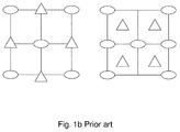
- Fig. 1b shows a gas supplying port according to the conventional prior art.
- the gas 223 and gas 224 are provided by different gas supplying ports respectively, and are sprayed into the reaction chamber 200.
- the gas supplying ports of the gas supplying mechanism 221 are orthogonal or crisscross arranged as shown in Fig. 1b .
- the orthogonal or crisscross arrangement could not make the kinds of reaction gas to be mixed well.
- the diethylzinc (DEZn(g)) gas is mixed with the water vapor (H 2 O (g) ) for reaction, the zinc oxide (ZnO) thin film and acetylene gas (C 2 H 2 ) are generated in the reaction chamber only after the two kinds of gas are mixed well.
- the design of the gas supplying port limits the gas mixing region, as shown in the hatching area in Fig. 1c , such that the efficiency for the gas mixing and the reaction is far from optimum in the reaction chamber.
- the acetylene gas is flammable and needs to be removed. Removing the acetylene gas increases the difficultly of controlling the gas uniformity.
- the construction of gas supplying mechanism in the thin film processing equipment needs to be improved.
- US 4,798,166 A describes an apparatus for thin film deposition including a reaction chamber, a supporting and conveying mechanism for a substrate and a gas supplying equipment for providing three different gases into the reaction chamber.
- the gas supplying equipment is formed like a concentric triplicate conduit.
- US 6,416,292 B1 and WO 2006/20424 A2 describe injectors for vaporous substances.
- US 2010/0092668 A1 discloses a showerhead for vapor deposition wherein in one embodiment, in a gas manifold assembly to be used in a CVD reactor, two concentric channels in a tube are provided for two independent and exclusive gas flow paths. Gas passageways into these two channels are arranged at the sides from two respective chambers surrounding the tube at different levels.
- a further objective of the present invention is to provide a thin film processing equipment provided with a gas supplying mechanism, spraying different kinds of gas to be mixed well, which improves the efficiency of gas mixing and gas reaction such that the quality and uniformity of the thin film become better.
- the distance between the gas supplying mechanism and the substrate can be adjusted to control the formation of the thin film, such that to improve the quality and efficiency of the formation of the thin film.
- the heating device is provided for heating and insulating the tray and for heating the substrate thereon, such that the reaction can be performed successfully.
- the present disclosure provides a thin film processing equipment with the construction described as follows.
- a tray is provided for supporting a substrate.
- a reaction chamber which is also a sealed chamber has a top side and bottom side corresponding to the top side.
- a gas supplying mechanism is disposed in the top side of the reaction chamber and is provided with a pair of gas supplying ports separated from each other for spraying down different kinds of gas.
- a transferring mechanism is disposed in the bottom side of the reaction chamber for transferring the tray and the substrate into the reaction chamber.
- the thin film processing equipment is characterized in that the pair of gas supplying ports of the gas supplying mechanism is in form of a concentric-circles structure.
- a tray if provided for supporting a substrate.
- a reaction chamber which is a sealed chamber has a top side and a bottom side corresponding to the top side.
- a gas supplying mechanism disposed in the top side of the reaction chamber.
- the gas supplying mechanism is provided with a plurality of gas supplying ports in form of a concentric-circles structure, and each of the concentric-circles structure is separated from each other for spraying down different kinds of gas.
- the different kinds of reaction gas are sprayed down through an inner tube and an outer tube of the plurality of gas supplying ports in form of a concentric-circles structure respectively.
- a transferring mechanism disposed in the bottom side of the reaction chamber is provided for transferring the tray and the substrate into the reaction chamber.
- the present disclosure also provides a thin film processing system described as follows.
- a tray is provided for supporting a substrate.
- a first reaction chamber is provided with a heating device.
- a reaction chamber is separated from the first reaction chamber by a first valve.
- the reaction chamber includes a top side and a bottom side corresponding to the top side.
- a second reaction chamber is separated from the reaction chamber by a second valve for providing a cooling environment.
- a transferring mechanism is disposed in the first reaction chamber, the second reaction chamber and the reaction chamber for transferring the tray and the substrate into each of the reaction chambers.
- the thin film processing system is characterized in that: a gas supplying mechanism is disposed in the top side of the reaction chamber, and the gas supplying mechanism is provided with a plurality of gas supplying ports in form of a concentric-circles structure.
- Each of gas supplying ports in form of a concentric-circles structure is separated from each other for spraying down different kinds of gas.
- the different kinds of reaction gas are sprayed down through an inner tube and an outer tube of the gas supplying ports in form of a concentric-circles structure respectively.
- the present disclosure also provides a process for depositing a thin film on a substrate.
- the process includes the step of providing a tray for supporting a substrate.
- the step of providing a reaction chamber which is a sealed chamber has a top side and a bottom side corresponding to the top side.
- the step of providing a gas supplying mechanism disposed in the top side of the reaction chamber.
- the gas supplying mechanism is provided with at least a pair of gas supplying ports in form of a concentric-circles structure and separated from each other for spraying down different kinds of gas. The gas can be sprayed down through each of the gas supplying ports in form of a concentric-circles structure.
- the different kinds of reaction gas are sprayed down through an inner tube and an outer tube of the gas supplying ports in form of a concentric-circles structure respectively.
- the gas supplying mechanism provided with a gas supplying port in form of a concentric-circles structure enables the kinds of reaction gas to be mixed well, regulates the distance between the gas supplying port and the substrate, maintains the temperature of the substrate to control the progress and efficiency of the thin film formation, and suits the formation of various thin films.
- the present invention relates to the construction and the function of a thin film processing equipment 1 and a process for depositing a thin film 2.
- a metal organic chemical vapor deposition technology MOCVD
- MOCVD metal organic chemical vapor deposition technology
- the metal organic chemical vapor deposition technology will be represented with MOCVD subsequently to make the specification readable.
- the construction and the function of the thin film processing equipment 1 based on MOCVD have been known to persons of ordinary skill in the art and need not to be discussed in any length herewith. Thus, only the characteristics of the thin film processing equipment 1 and the process for depositing a thin film 2 are described in detail. Also, the accompanying drawings referred by the following description are intended to show the characteristics of the present invention and are not made to scale.
- Fig. 2a shows the vertical view of a gas supplying port of a gas supplying mechanism in the thin film processing equipment
- Fig. 2b shows the cross-sectional view of the gas supplying port of the gas supplying mechanism in the thin film processing equipment
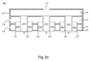
- Fig. 2c shows the cross-sectional view of the gas supplying mechanism which is provided with a plurality of gas supplying ports in the thin film processing equipment.
- the gas supplying port 21 of the gas supplying mechanism 20 is designed to be in form of a concentric-circles structure.
- the gas supplying port 21 includes an inner tube 214 forming a first flow channel 2141, an outer tube 215 forming a second flow channel 2151 and a shell 216 covering the inner tube 214 and the outer tube 215.
- different kinds of gas are sprayed down from the gas supplying mechanism through the first flow channel 2141 and the second flow channel 2151 respectively.
- the diethylzinc (DEZn (g) ) gas is sprayed down through the first flow channel 2141 and the water vapor (H 2 O (g) ) is sprayed down through the second flow channel 2151.
- the present invention does not limit which one of the kinds of the reaction gas is sprayed down through the first flow channel 2141 or the second flow channel 2151.
- the water vapor (H 2 O (g) ) can be sprayed through the first flow channel 2141 and the diethylzinc (DEZn (g) ) gas can be sprayed by the second flow channel 2151.
- the bis (methyl cyclopentadienyl) magnesium ((Mg(CH 3 C 5 H 4 ) 2(g) ) ) gas is sprayed down through the first flow channel 2141 and the tetrafluoromethane (CF 4(g) ) gas is sprayed down thorough the second flow channel 2151 and vice versa.
- the present invention does not limit which one of the kinds of the reaction gas is sprayed down through the first flow channel 2141 or the second flow channel 2151, and does not limit which type of thin film can be formed in this way.
- the source gas of the metal-organic magnesium (metal-organic Mg) includes: bis(cyclopentadientyl)magnesium (Mg(C 5 H 5 ) 2 ), bis(cyclopentadientyl)magnesium in squalane (Mg(C 5 H 5 ) 2 in C 30 H 62 ) , bis(methylcyclopentadienyl) magnesium (Mg(CH 3 C 5 H 4 ) 2 ), and bis(isopropylcyclopentadienyl)magnesium (Mg(i-C 3 H 7 C 5 H 4 ) 2 .
- the source gas of fluoride (F) includes tetrafluoromethane (CF 4 ), tetrafluoroethane (C 2 F 4 ), hexafluoroethane (C 2 F 6 ) , octafluoropropane (C 3 F 8 ), nitrogen trifluoride (NF 3 ), fluorine (F 2 ), hydrogen fluoride (HF), and chlorine trifluoride (C1F 3 ).
- the gas supplying mechanism 20 can increase the gas mixing efficiency as shown in the hatching area in Fig. 3 and obviously improve the drawback of small mixing area in the conventional prior arts. Furthermore, the gas mixing state of the gas supplying port 21 in form of a concentric-circle structure can be anticipated by calculating and adjusting the optimal distance between the gas supplying port 21 of the gas supplying mechanism 20 and the substrate 33, such that the thin film formation efficiency can be improved, and this part will be described subsequently.
- the gas supplying port 21 in form of a concentric-circle structure of the gas supplying mechanism 20 is constructed by two tubes with different length including an inner tube 214 and an outer tube 215.
- the inner tube 214 is longer than the outer tube 215, and the outer diameter of the inner tube 214 is smaller than that of the inner diameter of the outer tube 215.
- the inner diameter of inner tube 214 with is in a range from 0.6 mm to 1.0 mm; the outer diameter of the inner tube 214 is in a range from 1.6 mm to 2.0 mm; the inner diameter of the outer tube 215 is in a range from 3.0 mm to 4.0 mm; and the outer diameter of the outer tube 215 is in a range from 4.0 mm to 5.0 mm.
- the material of the inner tube 214 and the outer tube 215 includes stainless steel (SUS304, SUS316. SUS316L), carbon composite or graphite.
- the surface of the inner tube 214 and the outer tube 215 of the gas supplying mechanism 20 is treated with diamond-like carbon (DLC), silicon dioxide (SiO 2 ) or silicon carbide (SiC) to change the surface characteristic, and make the surface denser and not being corroded by the reaction gas.
- DLC diamond-like carbon
- SiO 2 silicon dioxide
- SiC silicon carbide
- the other outlet of inner tube 214 and the other outlet of the outer tube 215 are connected with the different flow channels, wherein one end of the first flow channel 2141 formed by the inner tube 214 is an ejecting outlet of the gas supplying port 21, and the other end corresponding to the gas supplying port 21 is intercommunicated with a gas containing chamber 211.
- the gas can be introduced into the gas containing chamber 211 via a vent-hole 217.
- the reaction gas is sprayed down from the gas supplying port 21 through the first flow channel 2141.
- the other end of the second flow channel 2151 formed by the inner tube 215 is another ejecting outlet of the gas supplying port 21, and the other end corresponding to the gas supplying port 2 is intercommunicated with the second gas containing chamber 212.
- the reaction gas can be introduced into the second containing chamber 212.
- the reaction gas is sprayed down from the gas supplying port 21 through the second flow channel 2151.
- the different kinds of reaction gas will not contact to each other inside the gas supplying mechanism 20 due to the inner tube 214 is separated from the outer tube 215. Therefore, there is no danger of the gas reaction.
- the kinds of reaction gas introduced through respectively by the separated inner tube 214 and outer tube 215 will mix until those are sprayed down from the first flow channel 2141 and the second flow channel 215 respectively.
- a third gas containing chamber 213 is added into the gas supplying mechanism 20 in the present disclosure to provide a heat source which can be introduced into the third gas containing chamber 213 via a vent-hole 219 if necessary, such that the third gas containing chamber 213 can be kept thermal insulating.
- the third gas containing chamber 213 provides a heat source for the reaction gas passing through the second flow channel 2151, and keeps the temperature of the sprayed reaction gas within a range.
- the temperature of the sprayed reaction gas passing through the second flow channel 2151 is kept in a range from 60 °C to 70°C to prevent the dust sedimentation, coagulation or powder collection at the outlets of the first flow channel 2141 and the second flow channel 2151 of the gas supplying port 21 after the gas reaction which result in the blocking of the outlets of the first flow channel 2141 and the second flow channel 2151, which otherwise affecting the gas spraying efficiency, the thin film formation quality, the thin film uniformity, and the thin film formation rate.
- the methods of providing heat source of the third gas containing chamber 213 include adding the heat sources of higher temperature such as hot steam, hot water, or hot oil, introducing a heating device, and so on.
- the method of providing the heat source in the third gas containing chamber 213 is not limited in the present invention.
- the reaction between the substrate and the kinds of reaction gas will be performed till the temperature of surface of the substrate 33 reaches a specific temperature.
- another method of heating is to heat the substrate 33. The method of heating and maintaining temperature of the substrate 33 will be described in detail subsequently.
- FIG. 2c showing the cross-sectional view of the thin film processing equipment provided with the gas supplying mechanism formed by a plurality of gas supplying ports according to the present disclosure.
- the present disclosure provides a gas supplying mechanism 20 which is provided with a plurality of gas supplying ports 21.
- the gas supplying mechanism 20 is formed by connecting a plurality of gas supplying ports shown in Fig. 2b .
- the gas supplying mechanism 20 provided with a plurality of gas supplying ports 21 is formed by a first gas containing chamber, a plurality of second gas containing chamber 212, and a plurality of third gas containing chamber 213; and is intercommunicated with a plurality of first flow channel 2141 and a plurality of second flow channel 2151 through the first gas containing chamber and a plurality of second gas containing chamber 212.
- each of the second gas containing chambers 212 of the plurality of the gas supplying ports 21 are intercommunicated with each other, and each of the third gas containing chambers 213 are intercommunicated with each other.
- the gas is introduced into each of the second gas containing chamber 212 via the vent-hole 218, and when the second gas containing chamber 212 is full of the gas, the gas is sprayed down from each of the gas supplying ports 21 through each of the second flow channel 2151.
- a heat source is introduced into each of the third gas containing chamber 213 to keep each of the third gas containing chamber 213 thermal insulating and keep the temperature of the sprayed reaction gas passing through the second flow channel 2151 with a range.
- FIG. 3 showing the gas mixing state in the gas supplying port of the gas supplying mechanism.
- the two gas flows are mixed immediately after being sprayed down from the gas supplying port 21 of the gas supplying mechanism 20.
- the gas mixture can be set to become homogeneous once the gas mixture reaches the substrate 33 in favor of the reaction and the thin film formation.
- Fig. 4a shows another embodiment of the gas supplying mechanism in the present disclosure.
- the gas supplying port 21 in form of a plurality of concentric-circles structure is disposed in a carrier substrate 22a to form a bar-type gas supplying mechanism 20a.
- kinds of gas are introduced into the first gas containing chamber 211 via a first vent-hole 217 by designing different gas flow channels of the inner tube 214 and the outer tube 215.
- the reaction gas is sprayed down from the gas supplying port 21 through each of the first flow channel 2141.
- a reaction gas is introduced into the second gas containing chamber 212 via a second vent-hole 218.
- the reaction gas is sprayed down from the gas supplying port 21 through each of the second flow channel 2151.
- the number of gas supplying port 21 is not limited to form a gas supplying mechanism 20a.
- the distance between each of the concentric-circle in the plurality of the concentric-circles structures is not limited, such that a plurality of gas supplying ports with a concentric-circles structure can be arranged as required by the user.
- Fig. 4b shows another embodiment of the gas supplying mechanism in the present disclosure.
- a plurality of gas supplying ports 21 in form of a concentric-circles structure are disposed in a flat surface of the carrier substrate 22b to form a flat-type gas supplying mechanism 20b.
- the structure of the gas supplying port in form of a concentric-circles structure is the same as that of the above-mention, thus, it would not be described again.
- the number of the first vent-hole 217 through which the reaction gas passing the first flow channel 2141 can be one or more than one in the embodiment of Fig. 4a , Fig. 4b and Fig. 4c as required by the user.
- Fig. 4c shows another embodiment of the gas supplying mechanism in the present disclosure.
- a plurality of gas supplying port 21 in form of a concentric-circles structure are disposed in a flat surface of the carrier substrate 22b, to form a flat-type gas supplying mechanism 20b.
- the difference between Fig. 4c and Fig. 4b is the relative position of the gas supplying port 21, but due to the gas supplying port in form of a concentric-circles structure is the same as that of the above-mention, thus, it would not be described again.
- the number of the first vent-hole 217 through which the reaction gas passing the first flow channel 2141 can be one or more than one in the embodiment of Fig. 4a , Fig. 4b and Fig. 4c as required by the user.
- Fig. 5a shows an embodiment of the thin film processing equipment in this present disclosure.
- the thin film processing equipment 1 is used to deposit a thin film on a substrate 33.
- the thin film processing equipment 1 includes a reaction chamber 10, a gas supplying mechanism 20, a transferring mechanism 30 and a tray 31.
- the reaction chamber 10 is a sealed chamber in which kinds of reaction gas are reacted to form a thin film under a vacuum environment.
- the gas supplying mechanism 20 is disposed in the top side of the reaction chamber 10.
- the gas supplying mechanism 20 is provided with a gas supplying port 21 in form of a concentric-circles structure through which the reaction gas is sprayed down.
- the reaction gas can be sprayed down through the gas supplying port 21 in form of a concentric-circles structure of the gas supplying mechanism 20.
- the transferring mechanism 30 is constructed by a plurality of rolling devices 32 (e.g. a roller) disposed in the bottom side of the reaction chamber 10.
- the tray 31 is provided for supporting a substrate 33 and is contacted with the rolling device 32 to drive the tray 31 and the substrate 33 moving toward the A direction into the thin film processing equipment 1.
- the process for depositing a thin film in the thin film processing equipment 1 includes the following steps.
- the substrate 33 is disposed in the tray 31, and the tray 31 is moved toward the A direction by a rolling device 32 to introduce the tray 31 and the substrate 33 into the reaction chamber 10 of the thin film processing equipment 1.
- the valve (not shown in the figures) of the thin film processing equipment 1 is closed tightly.
- a pumping process is performed to make the reaction chamber being under a vacuum environment.
- the kinds of reaction gas is sprayed down from the gas supplying port 21 in form of a concentric-circles structure of the gas supplying mechanism 20, and are reacted to form a thin film on the substrate 33.
- the present embodiment is characterized in that the kinds of reaction gas are sprayed down by the gas supplying port 21 in form of a concentric-circles structure of the gas supplying mechanism 20.
- the diethylzinc (DEZn (g) ) gas is sprayed down through the first flow channel 2141 and the water vapor (H 2 O (g) ) is sprayed down through the second flow channel 2151 .
- the water vapor (H 2 O (g) ) is sprayed down through the first flow channel 2141 and the diethylzinc (DEZn (g) ) gas is sprayed down through the second flow channel 2151.
- the gas supplying mechanism 20 can increase the gas mixing efficiency as shown in the hatching area in Fig. 3 and obviously improve the drawback of small mixing area in the conventional prior art s.
- the design of the rolling device 32 of the transferring mechanism 30 in the thin film processing equipment 1 can be rolled clockwise or counterclockwise.
- the tray 31 and the substrate 33 can be moved toward the A direction or the B direction.
- the speed of the rolling device 32 can be kept to control the gas reaction and thus control the thin film formation rate and the thickness of thin film on the substrate 33. For example, if the thin film formation rate is fast, the speed of the rolling device 32 can be increased to control the thickness of the thin film. In contrast, if the thin film formation rate is slow, the speed of the rolling device 32 can be decreased.
- the gas supplying mechanism 20 in the thin film processing equipment 1 can be moved along the A direction or the B direction in the reaction chamber 10 as shown in Fig. 6a . Meanwhile, the gas supplying mechanism 20 can be moved up and down along the X direction and the Y direction in the reaction chamber 10 as shown in Fig. 6b . A direction and B direction are perpendicular to the X direction and the Y direction. Similarly, the thickness of the thin film and the formation rate can be controlled accurately by controlling the movement of the gas supplying mechanism 20.
- the method of moving the gas supplying mechanism 20 includes a stepper motor (not shown). Obviously, the previous embodiment using the gas supplying mechanism 20a can also be applied to be moved along the A direction or the B direction, or be moved up and down along the X direction or the Y direction in the reaction chamber 10.
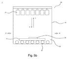
- the thin film processing equipment 1 includes a reaction chamber 10, a gas supplying mechanism 20b, a transferring mechanism 30, and a tray 31.
- the reaction chamber 10 is a sealed chamber in which kinds of the reaction gas can be introduced into the reaction chamber 10 to form the thin film under a vacuum environment.
- the gas supplying mechanism 20b is disposed in the top side of the reaction chamber 10.
- the gas supplying mechanism 20b is a flat carrier substrate 22b provided with a plurality of gas supplying ports 21 in form of a concentric-circles structure through which the reaction gas is sprayed down.
- the transferring mechanism 30 is constructed by a plurality of rolling devices 32 disposed in the bottom side of the reaction chamber 10.
- the tray 31 is provided for supporting a substrate 33 and contacting with the rolling device 32.
- the tray 31 and the substrate 33 are moved toward the A direction into the thin film processing equipment 1 by the rolling device 32.
- the difference between Fig. 5a and Fig. 5b is the gas supplying mechanism 20b, which is a flat carrier substrate 22b provided with a plurality of gas supplying ports 21 in form of a concentric-circles structure.
- the kinds of reaction gas can be sprayed down from the gas supplying port 21 in form of a concentric-circles structure of the gas supplying mechanism 20b to provide an area for forming the thin film.
- the thin film formation rate and the thickness of the thin film can be controlled accurately by moving the gas supplying mechanism 20b up and down along the X direction or the Y direction.
- Other process for depositing the thin film in Fig. 5b is the same as Fig. 5a , thus, it would not be described again.
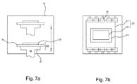
- FIG. 7a shows the moving of a heating device 40 in the thin film processing equipment 1 (rolling device 32 is not shown in Fig. 1a ).
- Fig. 7b is a top view of Fig. 7a .
- the movable heating device 40 is contacted with the tray 31 by the contact between a loading station 41 of the movable heating device 40 and the tray 31.
- the loading station 41 of the heating device 40 is capable of being moved up and down (e.g. being moved along the X direction or the Y direction).
- the tray 31 and the substrate 33 thereon are moved toward the gas supplying port 21 in form of a concentric-circles structure of the gas supplying mechanism 20.
- the distance between the gas supplying port 21 in form of a concentric-circles structure of the gas supplying mechanism 20 and the substrate 33 can be controlled by moving the loading station 41, which controls the thin film formation rate and the thickness of the thin film.
- the tray 31 is transferred forward or backward by the rolling of the rolling device 32.
- the dot line of Fig. 7b indicates the size of the loading station 41, and also shows the contact region between the loading station 41 and the tray 31.
- a heating device 40 is capable of heating, maintaining temperature, and moving up and down.
- the heating device 40 drives the tray 31 and substrate 33 by moving the loading station 41 up and down in the reaction chamber 10, to control the distance between the gas supplying port 21 and the substrate 33 during the thin film formation, such that the thin film formation efficiency can be effectively controlled.
- the heating device 40 is also capable of heating. The structure of the heating device 40 is described as follows.
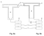
- Fig 8a shows a cross-sectional view of the heating device in the present disclosure.
- the heating device 40 is a hollow structure, and a storage region 42 is formed within the heating device 40.
- the storage region 42 can contain or store the heat source.
- the heat source is a kind of hot oil in this embodiment. After the oil in the oil source region 44 is heated by a heater 43, the hot oil is introduced into the storage region 42, so as to increase the temperature of the loading station 41 of the heating device 40. When the loading station 41 is raised and contacted with the tray 31, the heat is transmitted from the tray 31 to the substrate 33 and the surface temperature of the substrate 33 is increased.
- the surface temperature of the substrate 33 can be maintained in a certain temperature range to make the kinds of reaction gas reacted adjacently to the loading station 41 and then to extend the reaction time of the gas mixture and the substrate 33.
- the oil temperature is controlled by a temperature controller 45. It is emphasized that the reason for controlling the oil temperature to heat the substrate 33 is that the oil temperature can be controlled with accuracy of ⁇ 0.5°C. Meanwhile, the oil can be heated up to 350°C which is suitable for depositing the zinc oxide (ZnO) thin film (The operation temperature for the zinc oxide thin film is in a range from 180°C to 230 °C).
- the surface temperature of the substrate 33 can be accurately controlled, so as to control the thickness of the thin film formation accurately.
- the heating method for heating the oil in the oil source region 44 is not limited in this invention.
- the heating method also includes halogen, radiant heating, or electrical resistance heating.
- Fig 8b shows another embodiment of a vertical-sectional view of the heating device in this disclosure.
- a circulation line 46 is provided in the heating device 40.
- One end of the circulation line 46 is intercommunicated with the oil source region 44, and another end of that is connected with the oil source region 44.
- the embodiment also includes a temperature controller 45 which is used to set and control the temperature to increase the accuracy of temperature. In this way, the heated oil can be circulated in the circulation line 46 to keep the loading station 41 and the substrate 33 thereon at a set temperature.
- Fig. 9 shows the thickness controller and the sensor of the thin film processing equipment in this disclosure.
- the top of the thin film processing equipment 1 is provided with at least one sensor 51.
- the sensor 51 can be arranged to be spaced.
- the sensing method of this embodiment utilizes a laser or a light beam with a specific wavelength (not shown) to illuminate on the substrate 33.
- the sensor 51 detects the reflected light signal from the substrate 33, and the signal is transmitted to the thickness controller 50.
- the thickness or the characteristic of the thin film can be determined by the thickness controller 50. If the determined thickness of the thin film is insufficient, the supply level of the two kinds of reaction gas would be increased to accelerate the thin film formation rate.
- the thickness of the thin film is getting higher, the supply level of the two kinds of reaction gas would be decreased to slow down the thin film formation rate. If the quality of the thin film is changed, the ratio for the supply level of the two kinds of reaction gas, the temperature of the heater tuned by the temperature controller can be adjusted, such that the thin film quality can be tuned to be optimal. User can easily set and control the reaction rate of the thin film formation by setting up the thickness controller 50 and the sensor 51 in the thin film processing equipment 1.
- Fig. 10a shows the lateral view of one embodiment of the thin film processing equipment.
- Fig. 10b is a top view of Fig. 10a .
- the thin film processing equipment 1 includes a reaction chamber 10, a gas supplying mechanism 20, a transferring mechanism 30 and a tray 31.
- the reaction chamber 10 is a sealed chamber in which kinds of reaction gas are reacted to form a thin film under the vacuum environment.
- the gas supplying mechanism 20 is disposed in the top side of the reaction chamber 10.
- the gas supplying mechanism 20 is provided with a gas supplying port 21 in form of a concentric-circles structure through which the reaction gas is sprayed down.
- the reaction gas can be sprayed down through the gas supplying port 21 with concentric-circles structure of the gas supplying mechanism 20.
- the transferring mechanism 30 is constructed by a plurality of rolling devices 32 (e.g. a roller) disposed in the bottom side of the reaction chamber 10.
- the tray 31 is provided for supporting a substrate 33 and is contacted with the rolling device 32 to drive the tray 31 and the substrate 33 moving toward A direction into the thin film processing equipment 1.
- the supplying mechanism 20 e.g. the gas supplying mechanism in Fig. 2a
- the gas supplying mechanism 20a e.g. the gas supplying mechanism in Fig. 4a
- a first driving mechanism 22 such as a stepper motor
- the gas supplying mechanism 20 and the gas supplying mechanism 20a can be moved left and right in a second direction by a second driving mechanism 11 (such as a stepper motor) disposed in the top side of the reaction chamber 10.
- the gas supplying mechanism 20 and the gas supplying mechanism 20a can be moved along the two crisscross directions horizontally on the top side of the reaction chamber 10.
- the gas supplying mechanism 20 and the gas supplying mechanism 20a are can be moved left and right by the driving mechanism 11 and 22, such that the carrier substrate 31 and the substrate 33 can be covered in the moving range.
- a heating device 40 is further provided.
- the loading station 41 of the heating device 40 is contacted with the tray 31.
- the heating device 40 not only heats the substrate 33 disposed on the tray 31 but also raises the tray 31 and the substrate 33 to shorten the distance between the substrate 33 and gas supplying mechanism 20 and the gas supplying mechanism 20a to control the thin film formation.
- the driving mechanism 11 and the driving mechanism 12 in Fig. 10a and Fig. 10b are used in conventional technology, thus, the structure of the driving mechanism 11 and the driving mechanism 22 are not described in detail herein, and it would not affect the main feature of the present invention.
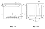
- Fig. 11a shows a lateral view of another embodiment of the thin film processing equipment in this disclosure and Fig. 11b is a top view of Fig. 11a.
- Fig. 11a shows an embodiment that the gas supplying mechanism 20 and the gas supplying mechanism 20a are added in the embodiment of Fig. 10a .
- the gas supplying mechanism 20 and the gas supplying mechanism 20a can be moved along the X direction or the Y direction in the reaction chamber 10, such that the thin film processing equipment 1 is capable of further controlling the thin film formation.
- the driving mechanism 11, 22 and a device driving the gas supplying mechanism 20, and 20a to be moved along the X direction or the Y direction in Fig. 11a and Fig. 11b are used in conventional technology, thus those are not described in detail herein, and it would not affected the main feature of the present invention.
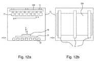
- the thin film processing equipment includes a reaction chamber 10, a gas supplying mechanism 20b, a transferring mechanism 30, and a tray 31.
- the reaction chamber 10 is a sealed chamber in which kinds of the reaction gas can be introduced into the reaction chamber 10 to form a thin film under a vacuum environment.
- the gas supplying mechanism 20b is disposed in the top side of the reaction chamber 10.
- the gas supplying mechanism 20b is a flat carrier substrate 22b provided with a plurality of gas supplying ports 21 in form of a concentric-circles structure through which the reaction gas is sprayed down to provide an area for forming the thin film.
- the transferring mechanism 30 is constructed by a plurality of rolling device 32 disposed in the bottom side of the reaction chamber 10.
- the tray 31 is provided for supporting a substrate 33 and contacting with the rolling device 32.
- the tray 31 and the substrate 33 are moved toward the A direction driving the tray 31 and the substrate 33 moving toward the A direction into the thin film processing equipment 1 by the rolling device 32.
- a heating device 40 is also provided in this embodiment.
- the loading station 41 of the heating device 40 is contacted with the tray 31.
- the heating device 40 not only heats the substrate 33 disposed on the tray 31 but also raises the tray 31 and the substrate 33 to shorten the distance between the substrate 33 and gas supplying mechanism 20 and the gas supplying mechanism 20a to control the thin film formation .
- Fig. 13a shows a lateral view of another embodiment of the thin film processing equipment in the present disclosure
- Fig. 13b shows a top view of Fig. 13a.
- Fig. 13a shows an embodiment that the function of driving the gas supplying mechanism 20b to be moved along the X direction or the Y direction in the reaction chamber 10 to adjust the distance between the substrate 33 and the gas supplying mechanism 20b, and thus decreasing the time for forming the thin film by the thin film processing equipment.
- Fig. 14 shows an embodiment of a thin film processing system.
- a plurality of thin film processing equipments 1 are connected to form the thin film processing system.
- the substrate 33 is disposed in the tray 31.
- the size of the substrate 33 is in a range from 300 mm x 300 mm to 2200 mm x 2500 mm, and the substrate 33 can be a glass substrate.
- the tray 31 and the substrate 33 are introduced into a first thin film processing equipment 1 along the A direction.
- a second thin film processing equipment 1b, a third thin film processing equipment 1c and a fourth thin film processing equipment 1d are pumped to be under the vacuum environment with the pressure lower than 0.01 Torr.
- Each of thin film processing equipments is separated from each other by a valve to well insulate the individual thin film processing equipments. When the valve is closed, the different thin film processing equipments would not be affected by each other, such that the thin film would not be contaminated by each other.
- the formation of zinc oxide (ZnO) thin film is an example to illustrate the operation of the thin film processing system in this embodiment.
- reaction gas diethylzinc (DEZn (g) ) gas and water vapor (H 2 O (g) )
- DEZn (g) diethylzinc
- H 2 O (g) water vapor
- the gas supplying mechanism 20 is a flat-type gas supplying mechanism 20b
- two kinds of reaction gas are sprayed out and mixed to form the thin film after each of the valve of the gas supplying ports 21 are closed.
- the gas flow can be pre-sprayed down from each of the plurality of gas supplying ports 21 over the tray 31 until the gas flow is under steady state, and then the two kinds of reaction gas are sprayed down to form a thin film on the substrate 33.
- the surface of the substrate 33 can be heated by contacting the loading station 41 (as shown in Fig. 7a ) of the heating device 40 with the tray 31 and the surface temperature of the substrate 33 is kept in a range from 140°C to 200°C to form a zinc oxide thin film on the substrate 33.
- the spray of the reaction gas is stopped.
- the tray 31 and the substrate 33 are transferred out from the second thin film processing equipment 1b, and are introduced into the third thin film processing equipment 1c. Meanwhile, based on the kind of reaction gas, the spraying rate, and the setting temperature of the substrate 33 provided by the third thin film processing equipment 1c, different types of thin film can be formed. For example, bis (methyl cyclopentadienyl) magnesium (Mg(CH 3 C 5 H 4 ) 2(g) ) gas is reacted with the tetrafluoromethane (CF 4(g) ) gas to form magnesium fluoride (MgF 2 ) thin film.
- Mg(CH 3 C 5 H 4 ) 2(g) bis (methyl cyclopentadienyl) magnesium
- CF 4(g) tetrafluoromethane
- the tray 31 and the substrate 33 can be further introduced into the fourth thin film processing equipment 1d to form another thin film. Because the thin film processing equipments 1a, 1b, 1c, and 1d are separated from each other and are not affected by each other, the thin film can be formed as the user's requirement.
- the tray 31 and the substrate 33 are introduced into a final thin film processing equipment 1 wherein the nitrogen (N 2 ) gas is provided to decrease the temperature to a range from 30°C to 60 °C to perform a following procedure.
- the gas supplying mechanism 20 of any of the thin film processing equipments 1 can be moved up and down or left and right. Meanwhile, the loading station 41 of the heating device 40 can be raised or descended to set the optimal distance between the gas supplying port 21 of the gas supplying mechanism 20 and the substrate 33 to optimally control the thickness of the thin film, and to finally produce thin films with higher quality.
- a feature of this invention is further illustrated by taking the formation of zinc oxide (ZnO) thin film for example.
- the diethylzinc (DEZn (g) ) gas is reacted with water vapor (H 2 O (g) ) not only to form an zinc oxide (ZnO) thin film, but acetylene (C 2 H 2 ) gas, a waste gas to be removed.
- the strengthened pumping is used in the conventional prior art. Unfortunately, over-strengthened pumping affects the uniformity of the stream of reaction gas.
- the reaction gas can be continuously sprayed down from the gas supplying port 21 to replace the acetylene gas, such that the thin film uniformity is not affected by the removal of acetylene gas.
- easy removal of the waste gas is an advantage of this invention.
- Fig. 15 shows a process flow of the process of depositing the thin film.
- the invention provides a process flow 2 for depositing a thin film on the substrate 33 including the steps below.
- Step 1501 a reaction chamber 10 is provided, which is a sealed chamber, in which the kinds of reaction gas are reacted to form a thin film in the reaction chamber 10.
- Step 1502 a gas supplying mechanism 20 provided with a gas supplying port 21 is provided and is disposed on the top side of the reaction chamber 10. The reaction gas is sprayed down through the gas supplying port 21, and the gas supply port is in form of a concentric-circles structure.
- Step 1503 a transferring mechanism 30 is provided and is disposed on the bottom side of the reaction chamber 10 for transferring the substrate 33.
- Step 1504 a heating device 40 is provided and is disposed under the transferring mechanism 30 with one side contacting with the bottom side of the transferring mechanism 30 to heat the substrate 33.
Landscapes
- Chemical & Material Sciences (AREA)
- General Chemical & Material Sciences (AREA)
- Chemical Kinetics & Catalysis (AREA)
- Engineering & Computer Science (AREA)
- Materials Engineering (AREA)
- Mechanical Engineering (AREA)
- Metallurgy (AREA)
- Organic Chemistry (AREA)
- Chemical Vapour Deposition (AREA)
Description
- The present invention relates to a thin film processing equipment and a process of forming the film using the same, and more particularly to a design of a gas supplying mechanism, which enables kinds of reaction gas to be mixed and accelerates the reaction in the thin film processing equipment.
- With the development of the semiconductor processing technology, the thin film processing equipments for depositing thin film on a substrate are increasingly used in various products. The major methods for forming the thin film include spattering, depositing and a metal organic chemical vapor deposition (MOCVD). MOCVD is generally used in forming the thin film in the solar photovoltaic industry regarding the advantages of the MOCVD described as follows.
- 1. By utilizing MOCVD, the components and dopants for forming the compound semiconductor material are introduced into the reaction chamber in the gaseous state. The gaseous flow and the introducing time can be regulated to accurately control the thin film components, dopant concentrations to form a thin film and ultra-thin film materials.
- 2. The reaction time of gaseous reactions varies from different kinds of gas, thus different reaction times are required in forming the compound semiconductor material. By utilizing MOCVD, the compound components and the dopant concentrations can be controlled and changed in the reaction chamber to suit the formation of heterogeneous structure, superlattice, or quantum-well.
- 3. Because the formation of the thin film is performed by pyrolysis reaction, the thin film uniformity can be controlled by regulating the reaction gaseous stream and the temperature profile in MOCVD. Thus, MOCVD can be applied to form multiple thin films or large-size thin films for the industrial mass production.
- 4. Because of the plasma reaction is not used in MOCVD technology, reaction chamber with lower vacuum degree requirement and simpler construction can fulfill the demand of production. Thus the cost of facility can be reduced.
- According to above advantages of the MOCVD, the development of MCVD-related technologies and equipments is vigorously increasing. The major method of performing MOCVD is mixing and reacting the organic metal gas with other kinds of gas. The different kinds of gas are provided by different gas supplying ports to introduce those kinds of gas into the reaction chamber to be reacted. Thus, the design of gas supplying port, the relative distance between the gas supplying port and the substrate, and the coordinating heating temperature affect the thin film quality of MOCVD technology and are always considered for designing the reaction chamber.
- Please refer to
Fig. 1a andFig 1b .Fig. 1a shows a thin film processing equipment according to the conventional prior art.Fig. 1b shows a gas supplying port according to the conventional prior art. As shown inFig. 1a , the gas 223 andgas 224 are provided by different gas supplying ports respectively, and are sprayed into thereaction chamber 200. In general, the gas supplying ports of thegas supplying mechanism 221 are orthogonal or crisscross arranged as shown inFig. 1b . However, the orthogonal or crisscross arrangement could not make the kinds of reaction gas to be mixed well. For example, when the gas supplying ports are crisscross arranged, the diethylzinc (DEZn(g)) gas is mixed with the water vapor (H2O(g)) for reaction, the zinc oxide (ZnO) thin film and acetylene gas (C2H2) are generated in the reaction chamber only after the two kinds of gas are mixed well. Obviously, the design of the gas supplying port limits the gas mixing region, as shown in the hatching area inFig. 1c , such that the efficiency for the gas mixing and the reaction is far from optimum in the reaction chamber. In addition, the acetylene gas is flammable and needs to be removed. Removing the acetylene gas increases the difficultly of controlling the gas uniformity. Thus, the construction of gas supplying mechanism in the thin film processing equipment needs to be improved. -
US 4,798,166 A describes an apparatus for thin film deposition including a reaction chamber, a supporting and conveying mechanism for a substrate and a gas supplying equipment for providing three different gases into the reaction chamber. The gas supplying equipment is formed like a concentric triplicate conduit.US 6,416,292 B1 andWO 2006/20424 A2 - In order to provide thin films having an improved quality, it is necessary to provide a uniform mixture of the gases for deposition. Thus, starting from the state of the art it is the object of the present application to provide a thin film processing equipment providing a uniform mixture of gases within the reaction chamber. It is a further object of the present invention to provide a method for thin film deposition resulting in improved mixture properties.
-
US 2010/0092668 A1 discloses a showerhead for vapor deposition wherein in one embodiment, in a gas manifold assembly to be used in a CVD reactor, two concentric channels in a tube are provided for two independent and exclusive gas flow paths. Gas passageways into these two channels are arranged at the sides from two respective chambers surrounding the tube at different levels. - The above-mentioned object is solved by the thin film processing equipment according to
claim 1 and the process for depositing a thin film on a substrate according toclaim 10. Advantageous improvements of the invention are described by dependent claims.
In order to solve the above problems in the prior art, a further objective of the present invention is to provide a thin film processing equipment provided with a gas supplying mechanism, spraying different kinds of gas to be mixed well, which improves the efficiency of gas mixing and gas reaction such that the quality and uniformity of the thin film become better. - It is another objective of the present invention to provide a thin film processing equipment provided with a gas supplying mechanism and a tray, in which the gas supplying mechanism can be moved up and down or moved around, and the tray can be moved up and down. Thus, the distance between the gas supplying mechanism and the substrate can be adjusted to control the formation of the thin film, such that to improve the quality and efficiency of the formation of the thin film.
- It is a further objective of the present invention to provide a thin film processing equipment provided with a heating device which can be moved up and down for each thin film processing equipment. The heating device is provided for heating and insulating the tray and for heating the substrate thereon, such that the reaction can be performed successfully.
- It is an objective of the present invention to provide a gas supplying mechanism to remove the waste gas during the gas spraying process, such that the cost of removing the waste gas can be reduced.
It is an objective of the present invention to provide a thin film processing equipment provided with a sensor to monitor the real-time progress of the thin film formation, such that the thin film formation can be maintained well and so as to improve the quality and the efficiency of the thin film formation.
It is an objective of the present invention to provide a process for depositing a thin film on a substrate, such that the efficiency of the thin film formation is improved and simplified in favor of the use by users.
According to above objectives, the present disclosure provides a thin film processing equipment with the construction described as follows. A tray is provided for supporting a substrate. A reaction chamber which is also a sealed chamber has a top side and bottom side corresponding to the top side. A gas supplying mechanism is disposed in the top side of the reaction chamber and is provided with a pair of gas supplying ports separated from each other for spraying down different kinds of gas. A transferring mechanism is disposed in the bottom side of the reaction chamber for transferring the tray and the substrate into the reaction chamber. The thin film processing equipment is characterized in that the pair of gas supplying ports of the gas supplying mechanism is in form of a concentric-circles structure. - The present disclosure then provides a thin film processing equipment with the construction described as follows. A tray if provided for supporting a substrate. A reaction chamber which is a sealed chamber has a top side and a bottom side corresponding to the top side. A gas supplying mechanism disposed in the top side of the reaction chamber. The gas supplying mechanism is provided with a plurality of gas supplying ports in form of a concentric-circles structure, and each of the concentric-circles structure is separated from each other for spraying down different kinds of gas. The different kinds of reaction gas are sprayed down through an inner tube and an outer tube of the plurality of gas supplying ports in form of a concentric-circles structure respectively. A transferring mechanism disposed in the bottom side of the reaction chamber is provided for transferring the tray and the substrate into the reaction chamber.
- The present disclosure also provides a thin film processing system described as follows. A tray is provided for supporting a substrate. A first reaction chamber is provided with a heating device. A reaction chamber is separated from the first reaction chamber by a first valve. The reaction chamber includes a top side and a bottom side corresponding to the top side. A second reaction chamber is separated from the reaction chamber by a second valve for providing a cooling environment. A transferring mechanism is disposed in the first reaction chamber, the second reaction chamber and the reaction chamber for transferring the tray and the substrate into each of the reaction chambers. The thin film processing system is characterized in that: a gas supplying mechanism is disposed in the top side of the reaction chamber, and the gas supplying mechanism is provided with a plurality of gas supplying ports in form of a concentric-circles structure. Each of gas supplying ports in form of a concentric-circles structure is separated from each other for spraying down different kinds of gas. The different kinds of reaction gas are sprayed down through an inner tube and an outer tube of the gas supplying ports in form of a concentric-circles structure respectively.
- The present disclosure also provides a process for depositing a thin film on a substrate. The process includes the step of providing a tray for supporting a substrate. The step of providing a reaction chamber which is a sealed chamber has a top side and a bottom side corresponding to the top side. The step of providing a gas supplying mechanism disposed in the top side of the reaction chamber. The gas supplying mechanism is provided with at least a pair of gas supplying ports in form of a concentric-circles structure and separated from each other for spraying down different kinds of gas. The gas can be sprayed down through each of the gas supplying ports in form of a concentric-circles structure. The different kinds of reaction gas are sprayed down through an inner tube and an outer tube of the gas supplying ports in form of a concentric-circles structure respectively. The step of providing a transferring mechanism disposed in the bottom side of the reaction chamber for transferring the tray and the substrate into the reaction chamber, such that the substrate is reacted with the different kinds of gas sprayed down by the gas supplying ports.
- According to the thin film processing equipment and the process for depositing a thin film on a substrate in the present disclosure, the gas supplying mechanism provided with a gas supplying port in form of a concentric-circles structure enables the kinds of reaction gas to be mixed well, regulates the distance between the gas supplying port and the substrate, maintains the temperature of the substrate to control the progress and efficiency of the thin film formation, and suits the formation of various thin films.
-
-
Fig. 1a schematically illustrates the conventional prior art; -
Fig. 1b schematically illustrates the gas supplying port of the gas supplying mechanism according to the conventional prior art; -
Fig. 1c schematically illustrates the gas mixing in the gas supplying ports of the gas supplying mechanism according to the conventional prior art; -
Fig. 2a schematically illustrates the vertical view of the gas supplying port of the gas supplying mechanism in the thin film processing equipment according to the present invention; -
Fig. 2b schematically illustrates the cross-sectional view of gas supplying port of the gas supplying mechanism in the thin film processing equipment according to the present invention; -
Fig. 2c schematically illustrates the cross-sectional view of the gas supplying mechanism provided with a plurality of gas supplying ports according to the present invention; -
Fig. 3 schematically illustrates the gas mixing in the gas supplying ports of the gas supplying mechanism according to the present invention; -
Fig. 4a schematically illustrates one embodiment of the substrate according to the present invention; -
Fig. 4b schematically illustrates another embodiment of the substrate; -
Fig. 4c schematically illustrates the other embodiment of the substrate; -
Fig. 5a schematically illustrates one embodiment of the thin film processing equipment according to the present disclosure; -
Fig. 5b schematically illustrates another embodiment of the thin film processing equipment according to the present disclosure; -
Fig. 6a schematically illustrates the movement of the gas supplying mechanism according to the present disclosure; -
Fig. 6b schematically illustrates another movement of the gas supplying mechanism according to the present disclosure; -
Fig. 7a schematically illustrates the load station of the heating device according to the present disclosure; -
Fig. 7b schematically illustrates the top view of the heating deviec according to the present disclosure; -
Fig. 8a schematically illustrates the cross-sectional view of one embodiment of the load station of the heating device according to the present disclosure; -
Fig. 8b schematically illustrates the cross-sectional view of another embodiment of the load station of the heating device according to the present disclosure; -
Fig. 9 schematically illustrates the thickness controller and the sensor of the thin film processing equipment according to the present disclosure; -
Fig. 10a schematically illustrates the lateral view of one embodiment of the thin film processing equipment according to the present disclosure; -
Fig. 10b schematically illustrates the top view of one embodiment of the thin film processing equipment according to the present disclosure; -
Fig. 11a schematically illustrates the lateral view of another embodiment of the thin film processing equipment according to the present disclosure; -
Fig. 11b schematically illustrates the top view of another embodiment of the thin film processing equipment according to the present disclosure; -
Fig. 12a schematically illustrates the lateral view of another embodiment of the thin film processing equipment according to the present disclosure; -
Fig. 12b schematically illustrates the top view of another embodiment of the thin film processing equipment according to the thin film processing equipment according to the present disclosure; -
Fig. 13a schematically illustrates the lateral view of another embodiment of the thin film processing equipment according to the present disclosure; -
Fig. 13b schematically illustrates the top view of another embodiment of the thin film processing equipment according to the present disclosure; -
Fig. 14 schematically illustrates one embodiment of the thin film processing system according to the present disclosure; and -
Fig. 15 schematically illustrates the process for depositing the thin film according to the present disclosure. - The present invention relates to the construction and the function of a thin
film processing equipment 1 and a process for depositing a thin film 2. For the illustration of the present invention, a metal organic chemical vapor deposition technology (MOCVD) is described herein. Meanwhile, the metal organic chemical vapor deposition technology will be represented with MOCVD subsequently to make the specification readable. The construction and the function of the thinfilm processing equipment 1 based on MOCVD have been known to persons of ordinary skill in the art and need not to be discussed in any length herewith. Thus, only the characteristics of the thinfilm processing equipment 1 and the process for depositing a thin film 2 are described in detail. Also, the accompanying drawings referred by the following description are intended to show the characteristics of the present invention and are not made to scale. - First, please refer to
Fig. 2a to Fig. 2c .Fig. 2a shows the vertical view of a gas supplying port of a gas supplying mechanism in the thin film processing equipment,Fig. 2b shows the cross-sectional view of the gas supplying port of the gas supplying mechanism in the thin film processing equipment, andFig. 2c shows the cross-sectional view of the gas supplying mechanism which is provided with a plurality of gas supplying ports in the thin film processing equipment. InFig. 2a , thegas supplying port 21 of thegas supplying mechanism 20 is designed to be in form of a concentric-circles structure. Thegas supplying port 21 includes aninner tube 214 forming afirst flow channel 2141, anouter tube 215 forming asecond flow channel 2151 and ashell 216 covering theinner tube 214 and theouter tube 215. Obviously, different kinds of gas are sprayed down from the gas supplying mechanism through thefirst flow channel 2141 and thesecond flow channel 2151 respectively. In one embodiment, to form a Zinc oxide (ZnO) film, the diethylzinc (DEZn(g)) gas is sprayed down through thefirst flow channel 2141 and the water vapor (H2O(g)) is sprayed down through thesecond flow channel 2151. The present invention does not limit which one of the kinds of the reaction gas is sprayed down through thefirst flow channel 2141 or thesecond flow channel 2151. In other words, the water vapor (H2O(g)) can be sprayed through thefirst flow channel 2141 and the diethylzinc (DEZn(g)) gas can be sprayed by thesecond flow channel 2151. - In another embodiment, to form a magnesium fluoride (MgF2) thin film as an anti-reflective coating layer (ARC), the bis (methyl cyclopentadienyl) magnesium ((Mg(CH3C5H4)2(g)) ) gas is sprayed down through the
first flow channel 2141 and the tetrafluoromethane (CF4(g)) gas is sprayed down thorough thesecond flow channel 2151 and vice versa. The present invention does not limit which one of the kinds of the reaction gas is sprayed down through thefirst flow channel 2141 or thesecond flow channel 2151, and does not limit which type of thin film can be formed in this way. For example, to form a the magnesium fluoride thin film as the ARC film, the source gas of the metal-organic magnesium (metal-organic Mg) includes: bis(cyclopentadientyl)magnesium (Mg(C5H5)2), bis(cyclopentadientyl)magnesium in squalane (Mg(C5H5)2 in C30H62) , bis(methylcyclopentadienyl) magnesium (Mg(CH3C5H4)2), and bis(isopropylcyclopentadienyl)magnesium (Mg(i-C3H7C5H4)2. The source gas of fluoride (F) includes tetrafluoromethane (CF4), tetrafluoroethane (C2F4), hexafluoroethane (C2F6) , octafluoropropane (C3F8), nitrogen trifluoride (NF3), fluorine (F2), hydrogen fluoride (HF), and chlorine trifluoride (C1F3). - Provided with
gas supplying ports 21 in form of a concentric-circles structure, thegas supplying mechanism 20 can increase the gas mixing efficiency as shown in the hatching area inFig. 3 and obviously improve the drawback of small mixing area in the conventional prior arts. Furthermore, the gas mixing state of thegas supplying port 21 in form of a concentric-circle structure can be anticipated by calculating and adjusting the optimal distance between thegas supplying port 21 of thegas supplying mechanism 20 and thesubstrate 33, such that the thin film formation efficiency can be improved, and this part will be described subsequently. - Then, according to the cross-sectional view of
Fig. 2b , thegas supplying port 21 in form of a concentric-circle structure of thegas supplying mechanism 20 is constructed by two tubes with different length including aninner tube 214 and anouter tube 215. Theinner tube 214 is longer than theouter tube 215, and the outer diameter of theinner tube 214 is smaller than that of the inner diameter of theouter tube 215. For example, the inner diameter ofinner tube 214 with is in a range from 0.6 mm to 1.0 mm; the outer diameter of theinner tube 214 is in a range from 1.6 mm to 2.0 mm; the inner diameter of theouter tube 215 is in a range from 3.0 mm to 4.0 mm; and the outer diameter of theouter tube 215 is in a range from 4.0 mm to 5.0 mm. In addition, the material of theinner tube 214 and theouter tube 215 includes stainless steel (SUS304, SUS316. SUS316L), carbon composite or graphite. In one preferred embodiment, the surface of theinner tube 214 and theouter tube 215 of thegas supplying mechanism 20 is treated with diamond-like carbon (DLC), silicon dioxide (SiO2) or silicon carbide (SiC) to change the surface characteristic, and make the surface denser and not being corroded by the reaction gas. - Please refer to
Fig. 2b , the other outlet ofinner tube 214 and the other outlet of theouter tube 215 are connected with the different flow channels, wherein one end of thefirst flow channel 2141 formed by theinner tube 214 is an ejecting outlet of thegas supplying port 21, and the other end corresponding to thegas supplying port 21 is intercommunicated with agas containing chamber 211. Thus, the gas can be introduced into thegas containing chamber 211 via a vent-hole 217. When the firstgas containing chamber 211 is full of the reaction gas, the reaction gas is sprayed down from thegas supplying port 21 through thefirst flow channel 2141. The other end of thesecond flow channel 2151 formed by theinner tube 215 is another ejecting outlet of thegas supplying port 21, and the other end corresponding to the gas supplying port 2 is intercommunicated with the secondgas containing chamber 212. Thus, the reaction gas can be introduced into the second containingchamber 212. When the secondgas containing chamber 212 is full of the reaction gas, the reaction gas is sprayed down from thegas supplying port 21 through thesecond flow channel 2151. The different kinds of reaction gas will not contact to each other inside thegas supplying mechanism 20 due to theinner tube 214 is separated from theouter tube 215. Therefore, there is no danger of the gas reaction. Obviously, the kinds of reaction gas introduced through respectively by the separatedinner tube 214 andouter tube 215 will mix until those are sprayed down from thefirst flow channel 2141 and thesecond flow channel 215 respectively. - In addition, a third
gas containing chamber 213 is added into thegas supplying mechanism 20 in the present disclosure to provide a heat source which can be introduced into the thirdgas containing chamber 213 via a vent-hole 219 if necessary, such that the thirdgas containing chamber 213 can be kept thermal insulating. Thus, the thirdgas containing chamber 213 provides a heat source for the reaction gas passing through thesecond flow channel 2151, and keeps the temperature of the sprayed reaction gas within a range. For example, the temperature of the sprayed reaction gas passing through thesecond flow channel 2151 is kept in a range from 60 °C to 70°C to prevent the dust sedimentation, coagulation or powder collection at the outlets of thefirst flow channel 2141 and thesecond flow channel 2151 of thegas supplying port 21 after the gas reaction which result in the blocking of the outlets of thefirst flow channel 2141 and thesecond flow channel 2151, which otherwise affecting the gas spraying efficiency, the thin film formation quality, the thin film uniformity, and the thin film formation rate. In addition, the methods of providing heat source of the thirdgas containing chamber 213 include adding the heat sources of higher temperature such as hot steam, hot water, or hot oil, introducing a heating device, and so on. The method of providing the heat source in the thirdgas containing chamber 213 is not limited in the present invention. The reaction between the substrate and the kinds of reaction gas will be performed till the temperature of surface of thesubstrate 33 reaches a specific temperature. To increase the reaction duration between the surface of thesubstrate 33 and the kinds of reaction gas, another method of heating is to heat thesubstrate 33. The method of heating and maintaining temperature of thesubstrate 33 will be described in detail subsequently. - Please refer to
Fig. 2c , showing the cross-sectional view of the thin film processing equipment provided with the gas supplying mechanism formed by a plurality of gas supplying ports according to the present disclosure. As shown inFig. 2c , the present disclosure provides agas supplying mechanism 20 which is provided with a plurality ofgas supplying ports 21. Thegas supplying mechanism 20 is formed by connecting a plurality of gas supplying ports shown inFig. 2b . Apparently, in this embodiment, thegas supplying mechanism 20 provided with a plurality ofgas supplying ports 21 is formed by a first gas containing chamber, a plurality of secondgas containing chamber 212, and a plurality of thirdgas containing chamber 213; and is intercommunicated with a plurality offirst flow channel 2141 and a plurality ofsecond flow channel 2151 through the first gas containing chamber and a plurality of secondgas containing chamber 212. Wherein each of the secondgas containing chambers 212 of the plurality of thegas supplying ports 21 are intercommunicated with each other, and each of the thirdgas containing chambers 213 are intercommunicated with each other. Such that the gas is introduced into each of the secondgas containing chamber 212 via the vent-hole 218, and when the secondgas containing chamber 212 is full of the gas, the gas is sprayed down from each of thegas supplying ports 21 through each of thesecond flow channel 2151. Similarly, a heat source is introduced into each of the thirdgas containing chamber 213 to keep each of the thirdgas containing chamber 213 thermal insulating and keep the temperature of the sprayed reaction gas passing through thesecond flow channel 2151 with a range. Additionally, another kind of gas is introduced into the firsgas containing chamber 211 via the vent-hole 217, and when the firsgas containing chamber 211 is full of the gas, the gas is sprayed down from each of thegas supplying ports 21 through each of thesecond flow channel 2141. Obviously, a larger thin film processing can be executed in this embodiment. - Please refer to
Fig. 3 showing the gas mixing state in the gas supplying port of the gas supplying mechanism. InFig. 3 , the two gas flows are mixed immediately after being sprayed down from thegas supplying port 21 of thegas supplying mechanism 20. By optimal calculation and measurement, the gas mixture can be set to become homogeneous once the gas mixture reaches thesubstrate 33 in favor of the reaction and the thin film formation. - Then, please refer to
Fig. 4a. Fig. 4a shows another embodiment of the gas supplying mechanism in the present disclosure. - As shown in
Fig. 4a , thegas supplying port 21 in form of a plurality of concentric-circles structure is disposed in acarrier substrate 22a to form a bar-typegas supplying mechanism 20a. Similarly, based on the concentric-circles structure of thegas supplying port 21, kinds of gas are introduced into the firstgas containing chamber 211 via a first vent-hole 217 by designing different gas flow channels of theinner tube 214 and theouter tube 215. When the firstgas containing chamber 211 is full of the reaction gas, the reaction gas is sprayed down from thegas supplying port 21 through each of thefirst flow channel 2141. Meanwhile, a reaction gas is introduced into the secondgas containing chamber 212 via a second vent-hole 218. When the secondgas containing chamber 212 is full of the reaction gas, the reaction gas is sprayed down from thegas supplying port 21 through each of thesecond flow channel 2151. Obviously, the number ofgas supplying port 21 is not limited to form agas supplying mechanism 20a. Meanwhile, the distance between each of the concentric-circle in the plurality of the concentric-circles structures is not limited, such that a plurality of gas supplying ports with a concentric-circles structure can be arranged as required by the user. - Next, please refer to
Fig. 4b. Fig. 4b shows another embodiment of the gas supplying mechanism in the present disclosure. As shown inFig. 4b , a plurality ofgas supplying ports 21 in form of a concentric-circles structure are disposed in a flat surface of thecarrier substrate 22b to form a flat-typegas supplying mechanism 20b. The structure of the gas supplying port in form of a concentric-circles structure is the same as that of the above-mention, thus, it would not be described again. It is emphasized that, the number of the first vent-hole 217 through which the reaction gas passing thefirst flow channel 2141 can be one or more than one in the embodiment ofFig. 4a ,Fig. 4b andFig. 4c as required by the user. - Next, please refer to
Fig. 4c. Fig. 4c shows another embodiment of the gas supplying mechanism in the present disclosure. As shown inFig. 4c , a plurality ofgas supplying port 21 in form of a concentric-circles structure are disposed in a flat surface of thecarrier substrate 22b, to form a flat-typegas supplying mechanism 20b. The difference betweenFig. 4c andFig. 4b is the relative position of thegas supplying port 21, but due to the gas supplying port in form of a concentric-circles structure is the same as that of the above-mention, thus, it would not be described again. It should be emphasized that the number of the first vent-hole 217 through which the reaction gas passing thefirst flow channel 2141 can be one or more than one in the embodiment ofFig. 4a ,Fig. 4b andFig. 4c as required by the user. - Please refer to
Fig. 5a. Fig. 5a shows an embodiment of the thin film processing equipment in this present disclosure. As shown inFig. 5a , the thinfilm processing equipment 1 is used to deposit a thin film on asubstrate 33. The thinfilm processing equipment 1 includes areaction chamber 10, agas supplying mechanism 20, atransferring mechanism 30 and atray 31. Thereaction chamber 10 is a sealed chamber in which kinds of reaction gas are reacted to form a thin film under a vacuum environment. Thegas supplying mechanism 20 is disposed in the top side of thereaction chamber 10. Thegas supplying mechanism 20 is provided with agas supplying port 21 in form of a concentric-circles structure through which the reaction gas is sprayed down. Thus, the reaction gas can be sprayed down through thegas supplying port 21 in form of a concentric-circles structure of thegas supplying mechanism 20. Thetransferring mechanism 30 is constructed by a plurality of rolling devices 32 (e.g. a roller) disposed in the bottom side of thereaction chamber 10. Thetray 31 is provided for supporting asubstrate 33 and is contacted with the rollingdevice 32 to drive thetray 31 and thesubstrate 33 moving toward the A direction into the thinfilm processing equipment 1. - Please refer to
Fig. 5a . The process for depositing a thin film in the thinfilm processing equipment 1 includes the following steps. Thesubstrate 33 is disposed in thetray 31, and thetray 31 is moved toward the A direction by a rollingdevice 32 to introduce thetray 31 and thesubstrate 33 into thereaction chamber 10 of the thinfilm processing equipment 1. The valve (not shown in the figures) of the thinfilm processing equipment 1 is closed tightly. A pumping process is performed to make the reaction chamber being under a vacuum environment. The kinds of reaction gas is sprayed down from thegas supplying port 21 in form of a concentric-circles structure of thegas supplying mechanism 20, and are reacted to form a thin film on thesubstrate 33. Obviously, the present embodiment is characterized in that the kinds of reaction gas are sprayed down by thegas supplying port 21 in form of a concentric-circles structure of thegas supplying mechanism 20. For example, to form of the zinc oxide (ZnO) film, the diethylzinc (DEZn(g)) gas is sprayed down through thefirst flow channel 2141 and the water vapor (H2O(g)) is sprayed down through thesecond flow channel 2151 . Alternatively, the water vapor (H2O(g)) is sprayed down through thefirst flow channel 2141 and the diethylzinc (DEZn(g)) gas is sprayed down through thesecond flow channel 2151. Provided with thegas supplying port 21 in form of a concentric-circles structure, thegas supplying mechanism 20 can increase the gas mixing efficiency as shown in the hatching area inFig. 3 and obviously improve the drawback of small mixing area in the conventional prior art s. - The design of the rolling
device 32 of thetransferring mechanism 30 in the thinfilm processing equipment 1 can be rolled clockwise or counterclockwise. Thus, thetray 31 and thesubstrate 33 can be moved toward the A direction or the B direction. The speed of the rollingdevice 32 can be kept to control the gas reaction and thus control the thin film formation rate and the thickness of thin film on thesubstrate 33. For example, if the thin film formation rate is fast, the speed of the rollingdevice 32 can be increased to control the thickness of the thin film. In contrast, if the thin film formation rate is slow, the speed of the rollingdevice 32 can be decreased. - The
gas supplying mechanism 20 in the thinfilm processing equipment 1 can be moved along the A direction or the B direction in thereaction chamber 10 as shown inFig. 6a . Meanwhile, thegas supplying mechanism 20 can be moved up and down along the X direction and the Y direction in thereaction chamber 10 as shown inFig. 6b . A direction and B direction are perpendicular to the X direction and the Y direction. Similarly, the thickness of the thin film and the formation rate can be controlled accurately by controlling the movement of thegas supplying mechanism 20. In addition, the method of moving thegas supplying mechanism 20 includes a stepper motor (not shown). Obviously, the previous embodiment using thegas supplying mechanism 20a can also be applied to be moved along the A direction or the B direction, or be moved up and down along the X direction or the Y direction in thereaction chamber 10. - Please refer to
Fig. 5b. Fig. 5b shows another embodiment of the thin film processing equipment. As shown inFig. 5b , the thinfilm processing equipment 1 includes areaction chamber 10, agas supplying mechanism 20b, atransferring mechanism 30, and atray 31. Thereaction chamber 10 is a sealed chamber in which kinds of the reaction gas can be introduced into thereaction chamber 10 to form the thin film under a vacuum environment. Thegas supplying mechanism 20b is disposed in the top side of thereaction chamber 10. Thegas supplying mechanism 20b is aflat carrier substrate 22b provided with a plurality ofgas supplying ports 21 in form of a concentric-circles structure through which the reaction gas is sprayed down. Thetransferring mechanism 30 is constructed by a plurality of rollingdevices 32 disposed in the bottom side of thereaction chamber 10. Thetray 31 is provided for supporting asubstrate 33 and contacting with the rollingdevice 32. Thetray 31 and thesubstrate 33 are moved toward the A direction into the thinfilm processing equipment 1 by the rollingdevice 32. The difference betweenFig. 5a andFig. 5b is thegas supplying mechanism 20b, which is aflat carrier substrate 22b provided with a plurality ofgas supplying ports 21 in form of a concentric-circles structure. Thus, the kinds of reaction gas can be sprayed down from thegas supplying port 21 in form of a concentric-circles structure of thegas supplying mechanism 20b to provide an area for forming the thin film. Thus, in this embodiment of theFig. 5b , the thin film formation rate and the thickness of the thin film can be controlled accurately by moving thegas supplying mechanism 20b up and down along the X direction or the Y direction. Other process for depositing the thin film inFig. 5b is the same asFig. 5a , thus, it would not be described again. - Please refer to
Fig. 7a and Fig. 7b showing the thin film processing equipment provided with the heating device.Fig. 7a shows the moving of aheating device 40 in the thin film processing equipment 1 (rollingdevice 32 is not shown inFig. 1a ).Fig. 7b is a top view ofFig. 7a . As shown inFig. 7a , after thetransferring mechanism 30 is introduced into thereaction chamber 10, themovable heating device 40 is contacted with thetray 31 by the contact between a loadingstation 41 of themovable heating device 40 and thetray 31. Wherein theloading station 41 of theheating device 40 is capable of being moved up and down (e.g. being moved along the X direction or the Y direction). Thetray 31 and thesubstrate 33 thereon are moved toward thegas supplying port 21 in form of a concentric-circles structure of thegas supplying mechanism 20. The distance between thegas supplying port 21 in form of a concentric-circles structure of thegas supplying mechanism 20 and thesubstrate 33 can be controlled by moving theloading station 41, which controls the thin film formation rate and the thickness of the thin film. In addition, according toFig. 7b , thetray 31 is transferred forward or backward by the rolling of the rollingdevice 32. The dot line ofFig. 7b indicates the size of theloading station 41, and also shows the contact region between the loadingstation 41 and thetray 31. - Next, the
substrate 33 is heated to increase the reaction time of the gas mixture and the surface of thesubstrate 33. Aheating device 40 is capable of heating, maintaining temperature, and moving up and down. Theheating device 40 drives thetray 31 andsubstrate 33 by moving theloading station 41 up and down in thereaction chamber 10, to control the distance between thegas supplying port 21 and thesubstrate 33 during the thin film formation, such that the thin film formation efficiency can be effectively controlled. Theheating device 40 is also capable of heating. The structure of theheating device 40 is described as follows. - Please refer to
Fig. 8a. Fig 8a shows a cross-sectional view of the heating device in the present disclosure. - As shown in
Fig. 8a , theheating device 40 is a hollow structure, and astorage region 42 is formed within theheating device 40. Thestorage region 42 can contain or store the heat source. For example, the heat source is a kind of hot oil in this embodiment. After the oil in theoil source region 44 is heated by aheater 43, the hot oil is introduced into thestorage region 42, so as to increase the temperature of theloading station 41 of theheating device 40. When theloading station 41 is raised and contacted with thetray 31, the heat is transmitted from thetray 31 to thesubstrate 33 and the surface temperature of thesubstrate 33 is increased. When thestorage region 42 of theheating device 40 is continuously heated in an oil bath, the surface temperature of thesubstrate 33 can be maintained in a certain temperature range to make the kinds of reaction gas reacted adjacently to theloading station 41 and then to extend the reaction time of the gas mixture and thesubstrate 33. Surely, the oil temperature is controlled by atemperature controller 45. It is emphasized that the reason for controlling the oil temperature to heat thesubstrate 33 is that the oil temperature can be controlled with accuracy of ±0.5°C. Meanwhile, the oil can be heated up to 350°C which is suitable for depositing the zinc oxide (ZnO) thin film (The operation temperature for the zinc oxide thin film is in a range from 180°C to 230 °C). Thus, due to the characteristics of the accuracy of temperature control and the wide temperature range, in this embodiment, the surface temperature of thesubstrate 33 can be accurately controlled, so as to control the thickness of the thin film formation accurately. Furthermore, the heating method for heating the oil in theoil source region 44 is not limited in this invention. The heating method also includes halogen, radiant heating, or electrical resistance heating. - Please refer to
Fig. 8b. Fig 8b shows another embodiment of a vertical-sectional view of the heating device in this disclosure. As shown inFig. 8b , acirculation line 46 is provided in theheating device 40. One end of thecirculation line 46 is intercommunicated with theoil source region 44, and another end of that is connected with theoil source region 44. When the oil in theoil source region 44 is heated by theheater 43, the oil is introduced into thecirculation line 46 by the pump, circulated back to theoil source region 44, and heated by theheater 43 again. Meanwhile, the embodiment also includes atemperature controller 45 which is used to set and control the temperature to increase the accuracy of temperature. In this way, the heated oil can be circulated in thecirculation line 46 to keep theloading station 41 and thesubstrate 33 thereon at a set temperature. - Please refer to
Fig. 9. Fig. 9 shows the thickness controller and the sensor of the thin film processing equipment in this disclosure. As shown inFig. 9 , the top of the thinfilm processing equipment 1 is provided with at least onesensor 51. Thesensor 51 can be arranged to be spaced. The sensing method of this embodiment utilizes a laser or a light beam with a specific wavelength (not shown) to illuminate on thesubstrate 33. Thesensor 51 detects the reflected light signal from thesubstrate 33, and the signal is transmitted to thethickness controller 50. The thickness or the characteristic of the thin film can be determined by thethickness controller 50. If the determined thickness of the thin film is insufficient, the supply level of the two kinds of reaction gas would be increased to accelerate the thin film formation rate. If the thickness of the thin film is getting higher, the supply level of the two kinds of reaction gas would be decreased to slow down the thin film formation rate. If the quality of the thin film is changed, the ratio for the supply level of the two kinds of reaction gas, the temperature of the heater tuned by the temperature controller can be adjusted, such that the thin film quality can be tuned to be optimal. User can easily set and control the reaction rate of the thin film formation by setting up thethickness controller 50 and thesensor 51 in the thinfilm processing equipment 1. - Then, to summarize and describe the aforementioned functions and operations of the thin film processing equipment, please refer to
Fig. 10a and Fig. 10b. Fig 10a shows the lateral view of one embodiment of the thin film processing equipment.Fig. 10b is a top view ofFig. 10a . As shown inFig. 10a , the thinfilm processing equipment 1 includes areaction chamber 10, agas supplying mechanism 20, atransferring mechanism 30 and atray 31. - The
reaction chamber 10 is a sealed chamber in which kinds of reaction gas are reacted to form a thin film under the vacuum environment. Thegas supplying mechanism 20 is disposed in the top side of thereaction chamber 10. Thegas supplying mechanism 20 is provided with agas supplying port 21 in form of a concentric-circles structure through which the reaction gas is sprayed down. Thus, the reaction gas can be sprayed down through thegas supplying port 21 with concentric-circles structure of thegas supplying mechanism 20. Thetransferring mechanism 30 is constructed by a plurality of rolling devices 32 (e.g. a roller) disposed in the bottom side of thereaction chamber 10. Thetray 31 is provided for supporting asubstrate 33 and is contacted with the rollingdevice 32 to drive thetray 31 and thesubstrate 33 moving toward A direction into the thinfilm processing equipment 1. In this embodiment, the supplying mechanism 20 (e.g. the gas supplying mechanism inFig. 2a ) and thegas supplying mechanism 20a (e.g. the gas supplying mechanism inFig. 4a ) can be moved forward and backward in a first direction driven by a first driving mechanism 22 (such as a stepper motor) disposed in the top side of thereaction chamber 10. Meanwhile, thegas supplying mechanism 20 and thegas supplying mechanism 20a can be moved left and right in a second direction by a second driving mechanism 11 (such as a stepper motor) disposed in the top side of thereaction chamber 10. Thus, thegas supplying mechanism 20 and thegas supplying mechanism 20a can be moved along the two crisscross directions horizontally on the top side of thereaction chamber 10. Thegas supplying mechanism 20 and thegas supplying mechanism 20a are can be moved left and right by thedriving mechanism 11 and 22, such that thecarrier substrate 31 and thesubstrate 33 can be covered in the moving range. In this embodiment, aheating device 40 is further provided. Theloading station 41 of theheating device 40 is contacted with thetray 31. Theheating device 40 not only heats thesubstrate 33 disposed on thetray 31 but also raises thetray 31 and thesubstrate 33 to shorten the distance between thesubstrate 33 andgas supplying mechanism 20 and thegas supplying mechanism 20a to control the thin film formation. Emphatically, thedriving mechanism 11 and the driving mechanism 12 inFig. 10a and Fig. 10b are used in conventional technology, thus, the structure of thedriving mechanism 11 and the driving mechanism 22 are not described in detail herein, and it would not affect the main feature of the present invention. - Please refer to
Fig. 11a and Fig. 11b. Fig. 11a shows a lateral view of another embodiment of the thin film processing equipment in this disclosure andFig. 11b is a top view ofFig. 11a. Fig. 11a shows an embodiment that thegas supplying mechanism 20 and thegas supplying mechanism 20a are added in the embodiment ofFig. 10a . Thegas supplying mechanism 20 and thegas supplying mechanism 20a can be moved along the X direction or the Y direction in thereaction chamber 10, such that the thinfilm processing equipment 1 is capable of further controlling the thin film formation. Similarly, thedriving mechanism 11, 22 and a device driving thegas supplying mechanism Fig. 11a and Fig. 11b are used in conventional technology, thus those are not described in detail herein, and it would not affected the main feature of the present invention. - Please refer to
Fig. 12a and Fig. 12b. Fig. 12a shows a lateral view of another embodiment of the thin film processing equipment, andFig. 12b shows a top view ofFig. 12a . As shown inFig. 12a , the thin film processing equipment includes areaction chamber 10, agas supplying mechanism 20b, atransferring mechanism 30, and atray 31. Thereaction chamber 10 is a sealed chamber in which kinds of the reaction gas can be introduced into thereaction chamber 10 to form a thin film under a vacuum environment. Thegas supplying mechanism 20b is disposed in the top side of thereaction chamber 10. Thegas supplying mechanism 20b is aflat carrier substrate 22b provided with a plurality ofgas supplying ports 21 in form of a concentric-circles structure through which the reaction gas is sprayed down to provide an area for forming the thin film. Thetransferring mechanism 30 is constructed by a plurality of rollingdevice 32 disposed in the bottom side of thereaction chamber 10. Thetray 31 is provided for supporting asubstrate 33 and contacting with the rollingdevice 32. Thetray 31 and thesubstrate 33 are moved toward the A direction driving thetray 31 and thesubstrate 33 moving toward the A direction into the thinfilm processing equipment 1 by the rollingdevice 32. Meanwhile, aheating device 40 is also provided in this embodiment. Theloading station 41 of theheating device 40 is contacted with thetray 31. Theheating device 40 not only heats thesubstrate 33 disposed on thetray 31 but also raises thetray 31 and thesubstrate 33 to shorten the distance between thesubstrate 33 andgas supplying mechanism 20 and thegas supplying mechanism 20a to control the thin film formation . - Please refer to
Fig. 13a and Fig. 13b. Fig. 13a shows a lateral view of another embodiment of the thin film processing equipment in the present disclosure andFig. 13b shows a top view ofFig. 13a. Fig. 13a shows an embodiment that the function of driving thegas supplying mechanism 20b to be moved along the X direction or the Y direction in thereaction chamber 10 to adjust the distance between thesubstrate 33 and thegas supplying mechanism 20b, and thus decreasing the time for forming the thin film by the thin film processing equipment. - Please refer to
Fig. 14. Fig. 14 shows an embodiment of a thin film processing system. As shown inFig. 14 , a plurality of thinfilm processing equipments 1 are connected to form the thin film processing system. First, thesubstrate 33 is disposed in thetray 31. The size of thesubstrate 33 is in a range from 300 mm x 300 mm to 2200 mm x 2500 mm, and thesubstrate 33 can be a glass substrate. Then, thetray 31 and thesubstrate 33 are introduced into a first thinfilm processing equipment 1 along the A direction. While the temperature of thesubstrate 33 is heated up to a range from 140°C to 220°C by a halogen lamp radiation, a second thinfilm processing equipment 1b, a third thinfilm processing equipment 1c and a fourth thinfilm processing equipment 1d are pumped to be under the vacuum environment with the pressure lower than 0.01 Torr. Each of thin film processing equipments is separated from each other by a valve to well insulate the individual thin film processing equipments. When the valve is closed, the different thin film processing equipments would not be affected by each other, such that the thin film would not be contaminated by each other. The formation of zinc oxide (ZnO) thin film is an example to illustrate the operation of the thin film processing system in this embodiment. When thesubstrate 33 is introduced into the second thinfilm processing equipment 1b, two kinds of reaction gas, diethylzinc (DEZn(g)) gas and water vapor (H2O(g)), are sprayed down in thereaction chamber 10 from thegas supplying mechanism 20 through thegas supplying port 21 in form of a concentric-circles structure. When thegas supplying mechanism 20 is a flat-typegas supplying mechanism 20b, two kinds of reaction gas are sprayed out and mixed to form the thin film after each of the valve of thegas supplying ports 21 are closed. When thegas supplying mechanism 20 is a bar-typegas supplying mechanism 20a, the gas flow can be pre-sprayed down from each of the plurality ofgas supplying ports 21 over thetray 31 until the gas flow is under steady state, and then the two kinds of reaction gas are sprayed down to form a thin film on thesubstrate 33. At the same time, the surface of thesubstrate 33 can be heated by contacting the loading station 41 (as shown inFig. 7a ) of theheating device 40 with thetray 31 and the surface temperature of thesubstrate 33 is kept in a range from 140°C to 200°C to form a zinc oxide thin film on thesubstrate 33. When a thickness of the ZnO thin film reaching a setting value is detected, the spray of the reaction gas is stopped. Then, thetray 31 and thesubstrate 33 are transferred out from the second thinfilm processing equipment 1b, and are introduced into the third thinfilm processing equipment 1c. Meanwhile, based on the kind of reaction gas, the spraying rate, and the setting temperature of thesubstrate 33 provided by the third thinfilm processing equipment 1c, different types of thin film can be formed. For example, bis (methyl cyclopentadienyl) magnesium (Mg(CH3C5H4)2(g)) gas is reacted with the tetrafluoromethane (CF4(g)) gas to form magnesium fluoride (MgF2) thin film. Similarly, when a thin film is formed in the third thinfilm processing equipment 1c, thetray 31 and thesubstrate 33 can be further introduced into the fourth thinfilm processing equipment 1d to form another thin film. Because the thinfilm processing equipments tray 31 and thesubstrate 33 are introduced into a final thinfilm processing equipment 1 wherein the nitrogen (N2) gas is provided to decrease the temperature to a range from 30°C to 60 °C to perform a following procedure. It should be noted that thegas supplying mechanism 20 of any of the thinfilm processing equipments 1 can be moved up and down or left and right. Meanwhile, theloading station 41 of theheating device 40 can be raised or descended to set the optimal distance between thegas supplying port 21 of thegas supplying mechanism 20 and thesubstrate 33 to optimally control the thickness of the thin film, and to finally produce thin films with higher quality. - A feature of this invention is further illustrated by taking the formation of zinc oxide (ZnO) thin film for example. The diethylzinc (DEZn(g)) gas is reacted with water vapor (H2O(g)) not only to form an zinc oxide (ZnO) thin film, but acetylene (C2H2) gas, a waste gas to be removed. In order to remove the waste gas, the strengthened pumping is used in the conventional prior art. Unfortunately, over-strengthened pumping affects the uniformity of the stream of reaction gas. Nevertheless, due to the well mixed gas mixture provided by the
gas supplying ports 21 in form of a concentric-circles structure of the gas supplying mechanism of the present invention, despite the acetylene (C2H2) gas is formed, the reaction gas can be continuously sprayed down from thegas supplying port 21 to replace the acetylene gas, such that the thin film uniformity is not affected by the removal of acetylene gas. Thus, easy removal of the waste gas is an advantage of this invention. - Please refer to
Fig. 15. Fig. 15 shows a process flow of the process of depositing the thin film. As shown inFig 15 , the invention provides a process flow 2 for depositing a thin film on thesubstrate 33 including the steps below. Step 1501: areaction chamber 10 is provided, which is a sealed chamber, in which the kinds of reaction gas are reacted to form a thin film in thereaction chamber 10. Step 1502: agas supplying mechanism 20 provided with agas supplying port 21 is provided and is disposed on the top side of thereaction chamber 10. The reaction gas is sprayed down through thegas supplying port 21, and the gas supply port is in form of a concentric-circles structure. Step 1503: a transferringmechanism 30 is provided and is disposed on the bottom side of thereaction chamber 10 for transferring thesubstrate 33. Step 1504: aheating device 40 is provided and is disposed under thetransferring mechanism 30 with one side contacting with the bottom side of thetransferring mechanism 30 to heat thesubstrate 33. - The present invention has been described by way of examples and with reference to the preferred embodiments and it is understood that the embodiments are not intended to limit the scope of the present invention. Moreover, as the contents disclosed herein should be readily understood and can be implemented by a person skilled in the art, all equivalent changes or modifications which do not depart from the scope of the appended claims.
Claims (11)
- A thin film processing equipment (1) comprising:a tray (31) for supporting a substrate (33);a reaction chamber (10), being a sealed chamber, having a top and a bottom corresponding to the top;a gas supplying mechanism (20) disposed in said top of said reaction chamber (10), provided with a set of gas supplying ports (21) including an inner tube (214) forming a first flow channel (2141), one end of said first flow channel (2141) being an ejecting outlet of said gas supplying port (21) and the other end which corresponds to said gas supplying port (21) being intercommunicated with a first gas containing chamber (211), and an outer tube (215) forming a second flow channel (2151), one end of said second flow channel (2151) being another ejecting outlet of said gas supplying port (21) and the other end which corresponds to said gas supplying port (21) being intercommunicated with a second gas containing chamber (212), wherein said first flow channel (2141) and said second flow channel (2151) are separated from each other for spraying down different kinds of gas; anda transferring mechanism (30) disposed in said bottom of said reaction chamber (10) for transferring said tray (31) and said substrate (33) into said reaction chamber (10);wherein said set of gas supplying ports (21) of said gas supplying mechanism (20) is in form of a concentric-circle structure, and in said top of said reaction chamber (10), and each port of said set of gas supplying ports (21) is in the same level,said thin film processing equipment (1) being characterized bya third gas containing chamber (213) accessible via a vent-hole (219) and suitable for receiving a heat source introduced via the vent-hole (219) to provide heat for the reaction gas passing through the second flow channel (2151) to keep the temperature of the sprayed reaction gas within a range.
- The thin film processing equipment according to Claim 1, wherein said gas supplying mechanism (20) is moved between two sides of said top of said reaction chamber (10) by a driving mechanism.
- The thin film processing equipment according to Claim 1 or 2, wherein said gas supplying mechanism (20) is moved between said top and said bottom of said reaction chamber (10) by a driving mechanism.
- The thin film processing equipment according to Claim 1, wherein said gas supplying mechanism (10) provided with said set of gas supplying ports (21) in form of the concentric-circle structure is a bar-type gas supplying mechanism.
- The thin film processing equipment according to Claim 4, wherein said bar-type gas supplying mechanism is moved between two sides of said top of said reaction chamber by a driving mechanism.
- The thin film processing equipment according to Claim 4, wherein said bar-type gas supplying mechanism is moved between said top and said bottom of said reaction chamber (10) by a driving mechanism.
- The thin film processing equipment according to Claim 1, wherein said gas supplying mechanism (20) provided with said set of gas supplying ports (21) in form of the concentric-circle structure is a flat-type gas supplying mechanism.
- The thin film processing equipment according to Claim 1, wherein said set of gas supplying ports (21) in form of the concentric-circle structure includes a shell (216) covering said inner circle tube (214) and said outer circle tube (215).
- The thin film processing equipment (1) according to Claim 1, further comprising a plurality of sensors (51) disposed in said top of said reaction chamber (10).
- A process for depositing a thin film on a substrate (33) comprising the step of:Providing (1502) a reaction chamber (10), being a sealed chamber, having a top and a bottom corresponding to the top;Providing (1503) a gas supplying mechanism (20) disposed in said top of said reaction chamber (10), provided with a set of gas supplying ports (21) in form of a concentric-circle structure and including an inner tube (214) forming a first flow channel (2141), one end of said first flow channel (2141) being an ejecting outlet of said gas supplying port (21) and the other end which corresponds to said gas supplying port (21) being intercommunicated with a first gas containing chamber (211), and an outer tube (215) forming a second flow channel (2151), one end of said second flow channel (2151) being another ejecting outlet of said gas supplying port (21) and the other end which corresponds to said gas supplying port (21) being intercommunicated with a second gas containing chamber (212), wherein said first flow channel (2141) and said second flow channel (2151) are separated from each other for spraying down different kinds of gas, and said set of gas supplying port (21) is in said top of said reaction chamber (10), each port of said set of gas supplying ports (21) is in the same level;providing a transferring mechanism (30) disposed in said bottom in said reaction chamber (10) for transferring said tray (31) and said substrate (33) into said reaction chamber (10), such that the substrate (33) is reacted with the different kinds of gas sprayed down by the gas supplying ports (21),said process being characterized in that a heat source is provided for introducing into a third gas containing chamber (213) via a vent-hole (219) for the reaction gas passing through the second flow channel (2151) to keep the temperature of the sprayed reaction gas within a range.
- A thin film processing system, comprising:a thin film processing equipment (1) according to one of Claims 1 to 9;a first reaction chamber equipped with a heating device and separated from said reaction chamber (10) of the thin film processing equipment by a first valve; anda second reaction chamber separated from said reaction chamber (10) of the thin film processing equipment (1) by a second valve, for providing a cooling environment,wherein the transferring mechanism (30) of the thin film processing equipment (1) is disposed in said first reaction chamber (10), said reaction chamber (10) of the thin film processing equipment (1) and said second reaction chamber for transferring said tray (31) of the thin film processing equipment (1) and a substrate into each of said first reaction chamber (10), said reaction chamber (10) of the thin film processing equipment (1) and said second reaction chamber.
Applications Claiming Priority (1)
| Application Number | Priority Date | Filing Date | Title |
|---|---|---|---|
| TW100133382A TWI512139B (en) | 2011-09-16 | 2011-09-16 | Thin film processing equipment and the process method thereof |
Publications (2)
| Publication Number | Publication Date |
|---|---|
| EP2570512A1 EP2570512A1 (en) | 2013-03-20 |
| EP2570512B1 true EP2570512B1 (en) | 2016-05-04 |
Family
ID=45440120
Family Applications (1)
| Application Number | Title | Priority Date | Filing Date |
|---|---|---|---|
| EP11192247.2A Not-in-force EP2570512B1 (en) | 2011-09-16 | 2011-12-06 | Thin film processing equipment and the processing method thereof |
Country Status (3)
| Country | Link |
|---|---|
| US (1) | US20130071567A1 (en) |
| EP (1) | EP2570512B1 (en) |
| TW (1) | TWI512139B (en) |
Families Citing this family (5)
| Publication number | Priority date | Publication date | Assignee | Title |
|---|---|---|---|---|
| KR101881894B1 (en) * | 2012-04-06 | 2018-07-26 | 삼성디스플레이 주식회사 | Thin film depositing apparatus and the thin film depositing method using the same |
| US9373551B2 (en) * | 2013-03-12 | 2016-06-21 | Taiwan Semiconductor Manufacturing Co., Ltd. | Moveable and adjustable gas injectors for an etching chamber |
| CN105132891A (en) * | 2015-08-24 | 2015-12-09 | 沈阳拓荆科技有限公司 | Application of novel temperature control system to low-temperature thin film preparation |
| JP6608332B2 (en) * | 2016-05-23 | 2019-11-20 | 東京エレクトロン株式会社 | Deposition equipment |
| CN111674063A (en) * | 2020-07-02 | 2020-09-18 | 镇江新成复合材料有限公司 | Small semi-automatic film processing device and miniaturized film processing method |
Citations (1)
| Publication number | Priority date | Publication date | Assignee | Title |
|---|---|---|---|---|
| US20100092668A1 (en) * | 2008-10-10 | 2010-04-15 | Alta Devices, Inc. | Concentric Showerhead For Vapor Deposition |
Family Cites Families (9)
| Publication number | Priority date | Publication date | Assignee | Title |
|---|---|---|---|---|
| US4798166A (en) * | 1985-12-20 | 1989-01-17 | Canon Kabushiki Kaisha | Apparatus for continuously preparing a light receiving element for use in photoelectromotive force member or image-reading photosensor |
| DE3925536A1 (en) * | 1989-08-02 | 1991-02-07 | Leybold Ag | ARRANGEMENT FOR THICKNESSING OF THICK FILMS |
| JP2776218B2 (en) * | 1993-10-12 | 1998-07-16 | 日本電気株式会社 | Laser CVD equipment |
| DE19921744B4 (en) * | 1999-05-11 | 2008-04-30 | Applied Materials Gmbh & Co. Kg | Method for transporting at least one vaporous substance through the wall of a vacuum chamber into the vacuum chamber and device for carrying out the method and its use |
| CN102154628B (en) * | 2004-08-02 | 2014-05-07 | 维高仪器股份有限公司 | Multi-gas distribution injector for chemical vapor deposition reactors |
| US7674352B2 (en) * | 2006-11-28 | 2010-03-09 | Applied Materials, Inc. | System and method for depositing a gaseous mixture onto a substrate surface using a showerhead apparatus |
| US20110033638A1 (en) * | 2009-08-10 | 2011-02-10 | Applied Materials, Inc. | Method and apparatus for deposition on large area substrates having reduced gas usage |
| TW201109462A (en) * | 2009-09-08 | 2011-03-16 | Ind Tech Res Inst | Coating machine with lifting system |
| TWI451521B (en) * | 2010-06-21 | 2014-09-01 | 細美事有限公司 | Substrate processing equipment and substrate processing method |
-
2011
- 2011-09-16 TW TW100133382A patent/TWI512139B/en not_active IP Right Cessation
- 2011-12-06 EP EP11192247.2A patent/EP2570512B1/en not_active Not-in-force
- 2011-12-22 US US13/335,441 patent/US20130071567A1/en not_active Abandoned
Patent Citations (1)
| Publication number | Priority date | Publication date | Assignee | Title |
|---|---|---|---|---|
| US20100092668A1 (en) * | 2008-10-10 | 2010-04-15 | Alta Devices, Inc. | Concentric Showerhead For Vapor Deposition |
Also Published As
| Publication number | Publication date |
|---|---|
| US20130071567A1 (en) | 2013-03-21 |
| TWI512139B (en) | 2015-12-11 |
| EP2570512A1 (en) | 2013-03-20 |
| TW201313949A (en) | 2013-04-01 |
Similar Documents
| Publication | Publication Date | Title |
|---|---|---|
| US11075127B2 (en) | Suppressing interfacial reactions by varying the wafer temperature throughout deposition | |
| US6872428B2 (en) | Apparatus and method for large area chemical vapor deposition using multiple expanding thermal plasma generators | |
| US11380556B2 (en) | Thermal atomic layer etch with rapid temperature cycling | |
| KR20230145004A (en) | Method and apparatus for reduction of defectivity in vapor deposited films | |
| US9385318B1 (en) | Method to integrate a halide-containing ALD film on sensitive materials | |
| KR101842675B1 (en) | Apparatus and method for plasma processing | |
| US20090035463A1 (en) | Thermal processing system and method for forming an oxide layer on substrates | |
| EP2570512A1 (en) | Thin film processing equipment and the processing method thereof | |
| US20120119337A1 (en) | Substrate processing apparatus, method of manufacturing semiconductor device and semiconductor device | |
| US9082694B2 (en) | Substrate processing apparatus, method for manufacturing substrate, and method for manufacturing semiconductor device | |
| US20070166459A1 (en) | Assembly and method for delivering a reactant material onto a substrate | |
| WO2019055317A1 (en) | Dielectric gapfill of high aspect ratio features utilizing a sacrificial etch cap layer | |
| TW201719801A (en) | System and device for flowable deposition in semiconductor manufacturing | |
| US20250213650A1 (en) | Etch selectivity control in atomic layer etching | |
| US12198925B2 (en) | Systems and methods for depositing low-k dielectric films | |
| US20130072000A1 (en) | Thin film processing equipment and the processing method thereof | |
| US20260022453A1 (en) | Selective molybdenum fill | |
| US20240381790A1 (en) | Techniques and apparatuses for processing chalcogenides | |
| CN103031535B (en) | Thin film process equipment and manufacturing method thereof | |
| CN103031534B (en) | Thin film process equipment and manufacturing method thereof | |
| TW201237994A (en) | System and apparatus for flowable deposition in semiconductor fabrication | |
| CN117026215A (en) | Multilayer film coating method based on vapor deposition | |
| US20260049396A1 (en) | Multi-station substrate processing chamber with precise temperature and flow control | |
| WO2026010831A1 (en) | Chamber precoat | |
| WO2024259292A1 (en) | Enhanced carbon film edge thickness profile tunability by focus ring |
Legal Events
| Date | Code | Title | Description |
|---|---|---|---|
| PUAI | Public reference made under article 153(3) epc to a published international application that has entered the european phase |
Free format text: ORIGINAL CODE: 0009012 |
|
| 17P | Request for examination filed |
Effective date: 20120709 |
|
| AK | Designated contracting states |
Kind code of ref document: A1 Designated state(s): AL AT BE BG CH CY CZ DE DK EE ES FI FR GB GR HR HU IE IS IT LI LT LU LV MC MK MT NL NO PL PT RO RS SE SI SK SM TR |
|
| AX | Request for extension of the european patent |
Extension state: BA ME |
|
| 17Q | First examination report despatched |
Effective date: 20131008 |
|
| GRAP | Despatch of communication of intention to grant a patent |
Free format text: ORIGINAL CODE: EPIDOSNIGR1 |
|
| INTG | Intention to grant announced |
Effective date: 20151113 |
|
| GRAS | Grant fee paid |
Free format text: ORIGINAL CODE: EPIDOSNIGR3 |
|
| GRAA | (expected) grant |
Free format text: ORIGINAL CODE: 0009210 |
|
| AK | Designated contracting states |
Kind code of ref document: B1 Designated state(s): AL AT BE BG CH CY CZ DE DK EE ES FI FR GB GR HR HU IE IS IT LI LT LU LV MC MK MT NL NO PL PT RO RS SE SI SK SM TR |
|
| REG | Reference to a national code |
Ref country code: GB Ref legal event code: FG4D |
|
| REG | Reference to a national code |
Ref country code: CH Ref legal event code: EP |
|
| REG | Reference to a national code |
Ref country code: AT Ref legal event code: REF Ref document number: 796990 Country of ref document: AT Kind code of ref document: T Effective date: 20160515 |
|
| REG | Reference to a national code |
Ref country code: IE Ref legal event code: FG4D |
|
| REG | Reference to a national code |
Ref country code: DE Ref legal event code: R096 Ref document number: 602011026122 Country of ref document: DE |
|
| REG | Reference to a national code |
Ref country code: NL Ref legal event code: MP Effective date: 20160504 |
|
| REG | Reference to a national code |
Ref country code: LT Ref legal event code: MG4D |
|
| PG25 | Lapsed in a contracting state [announced via postgrant information from national office to epo] |
Ref country code: NO Free format text: LAPSE BECAUSE OF FAILURE TO SUBMIT A TRANSLATION OF THE DESCRIPTION OR TO PAY THE FEE WITHIN THE PRESCRIBED TIME-LIMIT Effective date: 20160804 Ref country code: LT Free format text: LAPSE BECAUSE OF FAILURE TO SUBMIT A TRANSLATION OF THE DESCRIPTION OR TO PAY THE FEE WITHIN THE PRESCRIBED TIME-LIMIT Effective date: 20160504 Ref country code: FI Free format text: LAPSE BECAUSE OF FAILURE TO SUBMIT A TRANSLATION OF THE DESCRIPTION OR TO PAY THE FEE WITHIN THE PRESCRIBED TIME-LIMIT Effective date: 20160504 Ref country code: NL Free format text: LAPSE BECAUSE OF FAILURE TO SUBMIT A TRANSLATION OF THE DESCRIPTION OR TO PAY THE FEE WITHIN THE PRESCRIBED TIME-LIMIT Effective date: 20160504 |
|
| REG | Reference to a national code |
Ref country code: AT Ref legal event code: MK05 Ref document number: 796990 Country of ref document: AT Kind code of ref document: T Effective date: 20160504 |
|
| PG25 | Lapsed in a contracting state [announced via postgrant information from national office to epo] |
Ref country code: SE Free format text: LAPSE BECAUSE OF FAILURE TO SUBMIT A TRANSLATION OF THE DESCRIPTION OR TO PAY THE FEE WITHIN THE PRESCRIBED TIME-LIMIT Effective date: 20160504 Ref country code: RS Free format text: LAPSE BECAUSE OF FAILURE TO SUBMIT A TRANSLATION OF THE DESCRIPTION OR TO PAY THE FEE WITHIN THE PRESCRIBED TIME-LIMIT Effective date: 20160504 Ref country code: GR Free format text: LAPSE BECAUSE OF FAILURE TO SUBMIT A TRANSLATION OF THE DESCRIPTION OR TO PAY THE FEE WITHIN THE PRESCRIBED TIME-LIMIT Effective date: 20160805 Ref country code: HR Free format text: LAPSE BECAUSE OF FAILURE TO SUBMIT A TRANSLATION OF THE DESCRIPTION OR TO PAY THE FEE WITHIN THE PRESCRIBED TIME-LIMIT Effective date: 20160504 Ref country code: LV Free format text: LAPSE BECAUSE OF FAILURE TO SUBMIT A TRANSLATION OF THE DESCRIPTION OR TO PAY THE FEE WITHIN THE PRESCRIBED TIME-LIMIT Effective date: 20160504 Ref country code: ES Free format text: LAPSE BECAUSE OF FAILURE TO SUBMIT A TRANSLATION OF THE DESCRIPTION OR TO PAY THE FEE WITHIN THE PRESCRIBED TIME-LIMIT Effective date: 20160504 Ref country code: PT Free format text: LAPSE BECAUSE OF FAILURE TO SUBMIT A TRANSLATION OF THE DESCRIPTION OR TO PAY THE FEE WITHIN THE PRESCRIBED TIME-LIMIT Effective date: 20160905 |
|
| PG25 | Lapsed in a contracting state [announced via postgrant information from national office to epo] |
Ref country code: IT Free format text: LAPSE BECAUSE OF FAILURE TO SUBMIT A TRANSLATION OF THE DESCRIPTION OR TO PAY THE FEE WITHIN THE PRESCRIBED TIME-LIMIT Effective date: 20160504 |
|
| PG25 | Lapsed in a contracting state [announced via postgrant information from national office to epo] |
Ref country code: EE Free format text: LAPSE BECAUSE OF FAILURE TO SUBMIT A TRANSLATION OF THE DESCRIPTION OR TO PAY THE FEE WITHIN THE PRESCRIBED TIME-LIMIT Effective date: 20160504 Ref country code: CZ Free format text: LAPSE BECAUSE OF FAILURE TO SUBMIT A TRANSLATION OF THE DESCRIPTION OR TO PAY THE FEE WITHIN THE PRESCRIBED TIME-LIMIT Effective date: 20160504 Ref country code: DK Free format text: LAPSE BECAUSE OF FAILURE TO SUBMIT A TRANSLATION OF THE DESCRIPTION OR TO PAY THE FEE WITHIN THE PRESCRIBED TIME-LIMIT Effective date: 20160504 Ref country code: RO Free format text: LAPSE BECAUSE OF FAILURE TO SUBMIT A TRANSLATION OF THE DESCRIPTION OR TO PAY THE FEE WITHIN THE PRESCRIBED TIME-LIMIT Effective date: 20160504 Ref country code: SK Free format text: LAPSE BECAUSE OF FAILURE TO SUBMIT A TRANSLATION OF THE DESCRIPTION OR TO PAY THE FEE WITHIN THE PRESCRIBED TIME-LIMIT Effective date: 20160504 |
|
| REG | Reference to a national code |
Ref country code: DE Ref legal event code: R097 Ref document number: 602011026122 Country of ref document: DE |
|
| PG25 | Lapsed in a contracting state [announced via postgrant information from national office to epo] |
Ref country code: PL Free format text: LAPSE BECAUSE OF FAILURE TO SUBMIT A TRANSLATION OF THE DESCRIPTION OR TO PAY THE FEE WITHIN THE PRESCRIBED TIME-LIMIT Effective date: 20160504 Ref country code: BE Free format text: LAPSE BECAUSE OF FAILURE TO SUBMIT A TRANSLATION OF THE DESCRIPTION OR TO PAY THE FEE WITHIN THE PRESCRIBED TIME-LIMIT Effective date: 20160504 Ref country code: SM Free format text: LAPSE BECAUSE OF FAILURE TO SUBMIT A TRANSLATION OF THE DESCRIPTION OR TO PAY THE FEE WITHIN THE PRESCRIBED TIME-LIMIT Effective date: 20160504 Ref country code: AT Free format text: LAPSE BECAUSE OF FAILURE TO SUBMIT A TRANSLATION OF THE DESCRIPTION OR TO PAY THE FEE WITHIN THE PRESCRIBED TIME-LIMIT Effective date: 20160504 |
|
| PLBE | No opposition filed within time limit |
Free format text: ORIGINAL CODE: 0009261 |
|
| STAA | Information on the status of an ep patent application or granted ep patent |
Free format text: STATUS: NO OPPOSITION FILED WITHIN TIME LIMIT |
|
| 26N | No opposition filed |
Effective date: 20170207 |
|
| PG25 | Lapsed in a contracting state [announced via postgrant information from national office to epo] |
Ref country code: SI Free format text: LAPSE BECAUSE OF FAILURE TO SUBMIT A TRANSLATION OF THE DESCRIPTION OR TO PAY THE FEE WITHIN THE PRESCRIBED TIME-LIMIT Effective date: 20160504 |
|
| REG | Reference to a national code |
Ref country code: DE Ref legal event code: R119 Ref document number: 602011026122 Country of ref document: DE |
|
| PG25 | Lapsed in a contracting state [announced via postgrant information from national office to epo] |
Ref country code: MC Free format text: LAPSE BECAUSE OF FAILURE TO SUBMIT A TRANSLATION OF THE DESCRIPTION OR TO PAY THE FEE WITHIN THE PRESCRIBED TIME-LIMIT Effective date: 20160504 |
|
| REG | Reference to a national code |
Ref country code: CH Ref legal event code: PL |
|
| GBPC | Gb: european patent ceased through non-payment of renewal fee |
Effective date: 20161206 |
|
| REG | Reference to a national code |
Ref country code: FR Ref legal event code: ST Effective date: 20170831 |
|
| REG | Reference to a national code |
Ref country code: IE Ref legal event code: MM4A |
|
| PG25 | Lapsed in a contracting state [announced via postgrant information from national office to epo] |
Ref country code: LI Free format text: LAPSE BECAUSE OF NON-PAYMENT OF DUE FEES Effective date: 20161231 Ref country code: FR Free format text: LAPSE BECAUSE OF NON-PAYMENT OF DUE FEES Effective date: 20170102 Ref country code: LU Free format text: LAPSE BECAUSE OF NON-PAYMENT OF DUE FEES Effective date: 20161206 Ref country code: CH Free format text: LAPSE BECAUSE OF NON-PAYMENT OF DUE FEES Effective date: 20161231 |
|
| PG25 | Lapsed in a contracting state [announced via postgrant information from national office to epo] |
Ref country code: GB Free format text: LAPSE BECAUSE OF NON-PAYMENT OF DUE FEES Effective date: 20161206 Ref country code: DE Free format text: LAPSE BECAUSE OF NON-PAYMENT OF DUE FEES Effective date: 20170701 Ref country code: IE Free format text: LAPSE BECAUSE OF NON-PAYMENT OF DUE FEES Effective date: 20161206 |
|
| PG25 | Lapsed in a contracting state [announced via postgrant information from national office to epo] |
Ref country code: HU Free format text: LAPSE BECAUSE OF FAILURE TO SUBMIT A TRANSLATION OF THE DESCRIPTION OR TO PAY THE FEE WITHIN THE PRESCRIBED TIME-LIMIT; INVALID AB INITIO Effective date: 20111206 Ref country code: CY Free format text: LAPSE BECAUSE OF FAILURE TO SUBMIT A TRANSLATION OF THE DESCRIPTION OR TO PAY THE FEE WITHIN THE PRESCRIBED TIME-LIMIT Effective date: 20160504 |
|
| PG25 | Lapsed in a contracting state [announced via postgrant information from national office to epo] |
Ref country code: TR Free format text: LAPSE BECAUSE OF FAILURE TO SUBMIT A TRANSLATION OF THE DESCRIPTION OR TO PAY THE FEE WITHIN THE PRESCRIBED TIME-LIMIT Effective date: 20160504 Ref country code: MK Free format text: LAPSE BECAUSE OF FAILURE TO SUBMIT A TRANSLATION OF THE DESCRIPTION OR TO PAY THE FEE WITHIN THE PRESCRIBED TIME-LIMIT Effective date: 20160504 Ref country code: IS Free format text: LAPSE BECAUSE OF FAILURE TO SUBMIT A TRANSLATION OF THE DESCRIPTION OR TO PAY THE FEE WITHIN THE PRESCRIBED TIME-LIMIT Effective date: 20160504 |
|
| PG25 | Lapsed in a contracting state [announced via postgrant information from national office to epo] |
Ref country code: BG Free format text: LAPSE BECAUSE OF FAILURE TO SUBMIT A TRANSLATION OF THE DESCRIPTION OR TO PAY THE FEE WITHIN THE PRESCRIBED TIME-LIMIT Effective date: 20160504 |
|
| PG25 | Lapsed in a contracting state [announced via postgrant information from national office to epo] |
Ref country code: MT Free format text: LAPSE BECAUSE OF NON-PAYMENT OF DUE FEES Effective date: 20161206 |
|
| PG25 | Lapsed in a contracting state [announced via postgrant information from national office to epo] |
Ref country code: AL Free format text: LAPSE BECAUSE OF FAILURE TO SUBMIT A TRANSLATION OF THE DESCRIPTION OR TO PAY THE FEE WITHIN THE PRESCRIBED TIME-LIMIT Effective date: 20160504 |