EP2570342A1 - Aircraft window - Google Patents
Aircraft window Download PDFInfo
- Publication number
- EP2570342A1 EP2570342A1 EP20120178442 EP12178442A EP2570342A1 EP 2570342 A1 EP2570342 A1 EP 2570342A1 EP 20120178442 EP20120178442 EP 20120178442 EP 12178442 A EP12178442 A EP 12178442A EP 2570342 A1 EP2570342 A1 EP 2570342A1
- Authority
- EP
- European Patent Office
- Prior art keywords
- window
- seal
- seal part
- closing member
- volume resistivity
- Prior art date
- Legal status (The legal status is an assumption and is not a legal conclusion. Google has not performed a legal analysis and makes no representation as to the accuracy of the status listed.)
- Granted
Links
Images


Classifications
-
- B—PERFORMING OPERATIONS; TRANSPORTING
- B64—AIRCRAFT; AVIATION; COSMONAUTICS
- B64C—AEROPLANES; HELICOPTERS
- B64C1/00—Fuselages; Constructional features common to fuselages, wings, stabilising surfaces or the like
- B64C1/14—Windows; Doors; Hatch covers or access panels; Surrounding frame structures; Canopies; Windscreens accessories therefor, e.g. pressure sensors, water deflectors, hinges, seals, handles, latches, windscreen wipers
- B64C1/1476—Canopies; Windscreens or similar transparent elements
- B64C1/1492—Structure and mounting of the transparent elements in the window or windscreen
-
- B—PERFORMING OPERATIONS; TRANSPORTING
- B60—VEHICLES IN GENERAL
- B60J—WINDOWS, WINDSCREENS, NON-FIXED ROOFS, DOORS, OR SIMILAR DEVICES FOR VEHICLES; REMOVABLE EXTERNAL PROTECTIVE COVERINGS SPECIALLY ADAPTED FOR VEHICLES
- B60J10/00—Sealing arrangements
- B60J10/15—Sealing arrangements characterised by the material
- B60J10/16—Sealing arrangements characterised by the material consisting of two or more plastic materials having different physical or chemical properties
-
- B—PERFORMING OPERATIONS; TRANSPORTING
- B64—AIRCRAFT; AVIATION; COSMONAUTICS
- B64D—EQUIPMENT FOR FITTING IN OR TO AIRCRAFT; FLIGHT SUITS; PARACHUTES; ARRANGEMENT OR MOUNTING OF POWER PLANTS OR PROPULSION TRANSMISSIONS IN AIRCRAFT
- B64D45/00—Aircraft indicators or protectors not otherwise provided for
- B64D45/0015—Devices specially adapted for the protection against criminal attack, e.g. anti-hijacking systems
- B64D45/0063—Devices specially adapted for the protection against criminal attack, e.g. anti-hijacking systems by avoiding the use of electronic equipment during flight, e.g. of mobile phones or laptops
Definitions
- the present invention relates to a window of an aircraft having an electromagnetic shield and a closing member for an opening, and also relates to a gasket seal for use therein.
- HIRF High Intensity Radiated Fields
- electromagnetic noise radio wave and electromagnetic noise (hereinafter simply referred to as electromagnetic noise) emitted from various electronic equipment, such as portable telephones, game machines, notebook-sized personal computers, and PEDs (Personal Electro Devices), such as an active-type RFID (Radio Frequency IDentification) tag attached to air freight cargo
- an adverse effect can occur in, for example, communications with a control tower and communications and control of navigation for flight via a predetermined route.
- passengers are asked to refrain from using various electronic equipment inside aircraft.
- a film made of ITO (Indium Tin Oxide), gold, silver, or the like is provided as being inserted to the cabin window made by laminating a plurality of window panels made of acrylic or the like (for example, refer to Japanese Unexamined Patent Application Publication (Translation of PCT Application) No. 2003-523911 ).
- a conductive film which transmits light rays, has an electromagnetic shielding performance is held between window panels.
- the conductive film is composed of a film made of ITO, gold, silver, or the like; conductive fibers (Woven Mesh) plated with copper, nickel or the like; a printed mesh formed by printing an ink containing a conductive filler, such as silver on transparent PET (polyethylene terephthalate) or the like; or an expanded metal (mesh made of metal) made of a punched metal plate.
- the conductive films to be used for preventing invasion of electromagnetic noise need to be electrically bonded to the airframe.
- the conductive films are secured onto a retainer mounting frame made of a conductive material, such as aluminum, along the outer perimeter part of the window with an air-tight gasket seal interposed therebetween, by using fastener members, such as clamps, clips or the like made of a conductive material (for example, refer to U.S. Patent Publication No. 2007/0137117 Specification, U.S. Patent Publication No. 2008/0308677 Specification and U.S. Patent No. 7913385 Specification).
- the cabin window is mainly formed by using a stretched acrylic material, and the gasket seal that is fitted to the entire perimeter of the window is made of an EPDM rubber (ethylene-propylene-diene rubber) or a silicone rubber for the purpose of providing an air-tight sealing property, so as to maintain the air pressure inside the cabin from a low pressure of the outside of the airframe and prevent outside rain and moisture from invading therein.
- EPDM rubber ethylene-propylene-diene rubber
- silicone rubber for the purpose of providing an air-tight sealing property
- conductive rubbers have a conductive filler derived from metals such as pure Ag, Ag/Cu, Ag/Al, Ni/Cu, Ni/Al, Ag/C, Ni/C or the like, or graphite- carbon (C), mixed therein. Between this conductive rubber seal and a bonding surface of a clamp, a clip or the like made of aluminum on which the conductive rubber seal is bonded, the bonded state of dissimilar metals is formed in most cases, with the result that galvanic corrosion tends to occur under a moistened, humid or salt-water atmosphere environment to cause corrosion in an aluminum material on the airframe side.
- metals such as pure Ag, Ag/Cu, Ag/Al, Ni/Cu, Ni/Al, Ag/C, Ni/C or the like, or graphite- carbon (C), mixed therein.
- a method is proposed in which the bonding surface of an aluminum material is plated with a material, for example, nickel (Ni), tin (TIN) or chromate in order to avoid the anodic index or potential difference; however, high costs are required for the pretreatment (polishing) of the plating, masking treatments, plating processes, and the like.
- a material for example, nickel (Ni), tin (TIN) or chromate
- CRES corrosion resistance steel
- the present invention is devised in view of these technical problems, and has an object of providing a window of an aircraft, a closing member for an opening, and a gasket seal that can positively prevent electromagnetic noise, without causing galvanic corrosion relative to other parts on the periphery thereof.
- a window of an aircraft to be attached to an opening formed in an airframe of the aircraft includes a window body, a window frame that is to be provided on the inside of the opening and made of a conductive material, a gasket seal that is held between the outer perimeter part of the window body and the window frame, a fastener member that is made of a conductive material, and is used for securing the window body to the airframe with the gasket seal interposed therebetween, and the window body includes a transparent window panel, an electromagnetic shield film that is made of a conductive material and laminated on the window panel, and the gasket seal includes a first seal part that is made of a first conductive rubber-based material and interposed between the window panel and the window frame, and a second seal part that is made of a second conductive rubber-based material having a volume resistivity different from that of the first seal part, and is made in contact with the outer perimeter of the electromagnetic shield film.
- the volume resistivity of the first seal part is made smaller than the volume resistivity of the second seal part, on the first seal part, it is possible to prevent invasion and leakage of electromagnetic noise between the window panel and the window frame, and on the second seal part, it is possible to prevent galvanic corrosion from occurring relative to the fastener member that is made of a conductive material and used for securing the window body to the airframe.
- the volume resistivity of the first seal part may be set to, for example, 10 -3 to 5 ⁇ cm.
- the volume resistivity of the second seal part may be set to, for example, 300 to 10 8 ⁇ cm.
- the application of the present invention is not limited to the window of an aircraft, and the present invention is applicable to a closing member that closes an opening formed in a product, and is characterized by including a closing member body and a gasket seal that is held between the outer perimeter part of the closing member body and the opening, and the closing member body includes a closing member panel having a panel shape, an electromagnetic shield film that is made of a conductive material, and laminated on the closing member panel, and a fastener member that is made of a conductive material, and used for securing the closing member body to the opening with the gasket seal interposed therebetween, and the gasket seal includes a first seal part that is made of a first conductive rubber-based material and interposed between the closing member panel and the opening, and a second seal part that is made of a second conductive rubber-based material having a volume resistivity different from that of the first seal part, and is made in contact with the outer perimeter part of the electromagnetic shield film.
- a frame made of a conductive material may be provided between the gasket seal and the opening, or may be omitted.
- the present invention may be prepared as a gasket seal that is to be held between an opening formed in a product and a closing member that seals the opening, and the gasket seal is characterized by including a first seal part that is made of a first conductive rubber-based material and to be provided on one of surfaces of the closing member, and a second seal part that is made of a second conductive rubber-based material having a volume resistivity different from that of the first seal part, and to be provided on the other surface of the closing member.
- the gasket seal is formed by a first seal part and a second seal part that are different from each other in the volume resistivity, it is possible to prevent invasion and leakage of electromagnetic wave between the window panel and the window frame or between the closing member and the opening, and it also becomes possible to prevent galvanic corrosion from occurring relative to the fastener member.
- this arrangement by using a light-weight material, it is possible to obtain electromagnetic noise preventive effect and galvanic corrosion suppressive effect easily at low costs.
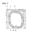
- FIG. 1 is a view that explains the structure of a cabin window 20 (window, closing member body) of an aircraft 10 in accordance with the present embodiment.
- the cabin window 20 is provided on the side face of an airframe of the aircraft 10.
- the cabin window 20 is attached to an opening 12 formed on a skin 11 made of a conductive material forming the airframe of the aircraft 10.
- the cabin window 20 includes a window part 21 and a window frame 30 that surrounds the entire perimeter part of the window part 21.
- the window part 21 is configured by laminating a plurality of, two in the present embodiment, window panels (closing member panels) 23A and 23B made of stretched acrylic plates.
- the cabin window 20 has a laminated type structure in which all the window panels 23A and 23B are made of stretched acrylic plates, with a resin film 24, made of polyurethane or the like for use in lamination, being held between the window panels 23A and 23B.
- a resin film 24, made of polyurethane or the like for use in lamination, being held between the window panels 23A and 23B.
- another air-gap-type structure is proposed in which an air layer is placed between the two window panels 23A and 23B
- the window panel 23A on the outside of the airframe has a tapered portion 23t, formed on the perimeter part thereof, that is gradually narrowed from the outside of the airframe toward the inside thereof.
- an electromagnetic shield mesh (electromagnetic shield film) 25, made of polyester fibers plated with cupper (Cu), black nickel (Ni) or the like for use in electromagnetic shielding, is formed.
- the electromagnetic shield film in place of the electromagnetic shield mesh 25, a printed mesh, an expanded metal member made of metal, or a conductive shield thin film made of a conductive material such as ITO, gold, silver, or the like, may also be used.
- the electromagnetic shield mesh 25 held by the window panels 23A and 23B has an area equivalent to the window panels 23A and 23B, with its perimeter part exposed to the perimeter part of the window part 21.
- a conductive paste 26 is applied onto the entire perimeter of the outer perimeter edge face 21s of the window part 21.
- the electromagnetic shield mesh 25, held by the window panels 23A and 23B, and the conductive paste 26 are electrically connected to each other.
- the conductive paste 26 is designed so as to prevent moisture from invading between the laminated window panels 23A and 23B.
- the window frame 30 is made of, for example, an aluminum alloy, and includes a fastener plate part 31 that abuts against the inner perimeter surface of the skin 11, a window panel holding part 32 that is located in an opening formed on the skin 11, and faces the tapered part 23t of the window part 21, and an edge wall part 33 that extends from the window panel holding part 32 toward the inside of the airframe.
- the window panel holding part 32 includes a tapered surface 32t, which faces the inside of the airframe, and is gradually narrowed from the inside of the airframe toward the outside of the airframe.
- a gasket seal 50 made of a conductive silicon rubber material, is provided between the outer perimeter part of the window panels 23A and 23B and the window frame 30, a gasket seal 50, made of a conductive silicon rubber material, is provided.
- the gasket seal 50 is formed into a ring shape so as to surround the entire perimeter of the outer perimeter part of the window panels 23A and 23B.
- the gasket seal 50 includes a first seal part 51 that abuts against the window frame 30, and a second seal part 52 that is placed along the window part 21 inside the airframe.
- One surface of the first seal part 51 is formed along the tapered portion 23t of the window panel 23A on the outside of the airframe, and the other surface thereof is formed so as to abut against the tapered surface 32t of the window panel holding part 32.
- the second seal part 52 has a structure having an L-letter shape in its cross section which is formed by an edge part 52a placed along the airframe inside surface 23c of the window panel 23B and an outer frame part 52b placed along the outer perimeter edge face 21s of the window part 21.
- the outer frame part 52b is provided so as to be tightly made in contact with the portion on the outer perimeter edge face 21s of the window part 21 to which the conductive paste 26 is applied.
- first seal part 51 and second seal part 52 are made of conductive rubber materials having mutually different volume resistivities.
- the first seal part 51 is made of a first conductive rubber material having a lower volume resistivity than that of the second seal part 52
- the second seal part 52 is made of a second conductive rubber material having a higher volume resistivity than that of the first seal part 51.
- the first seal part 51 is made of a first conductive silicone rubber material having, for example, a volume resistivity of 10 -3 to 5 ⁇ cm.
- the second seal part 52 is made of a second conductive silicone rubber material having, for example, a volume resistivity of 300 to 10 8 ⁇ cm.
- conductive EPDM rubber may be used as the materials for these conductive silicone rubber materials.
- mixing ratios of fillers made of conductive materials to be mixed into a silicone rubber material forming a base material can be made different.
- the examples of the conductive materials are Ag, Ag/Cu, Ag/Al, Ni/Cu, Ni/Al, C, Ag/C, Ni/C, etc.
- first seal part 51 and second seal part 52 are subjected to a curing treatment through thermosetting so that silicone rubbers are polymer-bonded into an integral structure with intermolecular bonding in which they are not separated from each other.
- the second seal part 52 of the gasket seal 50 is pushed onto the window panel 23A by one end 28a of a clamp (fastener member) 28 having a crank shape that is formed on the rear side of the gasket seal 50.
- the other end 28b of the clamp 28 is coupled to the edge wall part 33 of the window frame 30 through a clip (fastener member) 29 having an L-letter shape in its cross section.
- the clamp 28 and the clip 29 are made of, for example, an aluminum alloy, and are electrically connected to the window frame 30.
- the electromagnetic shield mesh 25 is electrically connected to the window frame 30 through the conductive paste 26, the second seal part 52, the clamp 28 and the clip 29.
- the grounded point by the clamp 28 is assumed to be a minimum point; however, the clamp 28 may have a structure that is continuously placed along the entire perimeter of the gasket seal 50 so as to improve its shielding performance.
- the electromagnetic shield mesh 25 is provided on the window part 21, and a gasket seal 50 is installed between the electromagnetic shield mesh 25 and the window frame 30 made of a conductive material.
- a gasket seal 50 is installed between the electromagnetic shield mesh 25 and the window frame 30 made of a conductive material.
- the electromagnetic shield mesh 25 of the window part 21 is electrically grounded to the window frame 30 through the second seal part 52 of the gasket seal 50, the clamp 28 and the clip 29 on the outer perimeter side of the window panels 23A and 23B.
- the second seal part 52 since the second seal part 52 has a high volume resistivity, it is possible to suppress generation of corrosion in the contact portions to the clamp 28, the clip 29, or the like.
- gasket seals having a volume resistivity of 1.7 ⁇ cm (Measurement 1), that of 5 ⁇ cm (Measurement 2), that of 210 ⁇ cm (Measurement 3), and that of 310 ⁇ cm (Measurement 4) were prepared.
- the acrylic plate except for comparative examples, shield mesh materials composed of polyester fibers of monofilaments copper-plated and black nickel-plated with a surface resistivity of 0.15 ⁇ /square were stacked and subjected to the tests.
- test pieces of gasket seals having 5 ⁇ cm and 310 ⁇ cm in volume resistivity were secured onto a plate made of A2024 aluminum alloy that had been subjected to an Alodine treatment, and onto this, salt water was sprayed over 500 hours. Moreover, 168 hours after the completion of the spraying process, the presence or absence of corrosion on the aluminum plate was confirmed.
- the gasket seal has a volume resistivity of 300 ⁇ cm or more, even in the case when a bonding surface is formed as a portion to which a cabin window is secured, by carrying out a chemical conversion coating process (MIL-DTL-5541 Class 3, MIL-DTL-81706 Class 3) on the surface of an aluminum having electrical conductivity, it is possible to prevent galvanic corrosion from occurring even under moistened, humid or salt-water spraying environment because the conductive rubber material having a high resistivity is used.
- a chemical conversion coating process MIL-DTL-5541 Class 3, MIL-DTL-81706 Class 3
- the above-mentioned structures are explained by exemplifying the cabin window 20; however, those structures may also be applied to door windows provided on doors of an aircraft and windows formed on a cockpit and side faces of the cockpit. Moreover, the present invention is also applicable to cases in which pressure seals and gaskets of openings such as doors, escape hatches or the like are made electrically conductive.
- FIG. 5 is a view that illustrates a structure in which the present invention is applied to a door window (window, closing member body) 60.
- the aforementioned electromagnetic shield mesh is held between window panels (closing member panels) 61A and 61B.
- This structure is the same as the cabin window 20 shown in FIG. 2 .
- a gasket seal 65 is electrically connected to a conductive paste 64 so as to be further connected to an end of an electromagnetic shield mesh (electromagnetic shield film) 63 through the conductive paste 64, and the gasket seal 65 includes a first seal part 51 made of a conductive rubber material having a low volume resistivity and a second seal part 52 made of a conductive rubber material having a volume resistivity that is higher than that of the first seal part 51.
- the gasket seal 65 is electrically grounded to a window frame 67 through a window retainer 66 (fastener member) along the entire perimeter thereof.
- each of the first seal part 51 and the second seal part 52 is formed into an integral structure with intermolecular bonding by using a thermosetting curing process; however, not limited to this, these may be formed by using a two-color injection molding process.
- the window panels 23A and 23B are made of a stretched acrylic material; however, these may be made of a polycarbonate resin or glass.
- the present invention may be applicable in the same manner to any case in which an attempt is made to prepare an electromagnetic shielding configuration in a closing member for use in closing an opening, and the application thereof is not intended to be limited.
- other applications include windows and sunroofs of automobiles, monitors for electronic apparatuses, lens protection filters for various cameras, and the like.
Landscapes
- Engineering & Computer Science (AREA)
- Aviation & Aerospace Engineering (AREA)
- Mechanical Engineering (AREA)
- Shielding Devices Or Components To Electric Or Magnetic Fields (AREA)
- Gasket Seals (AREA)
Abstract
Description
- The present invention relates to a window of an aircraft having an electromagnetic shield and a closing member for an opening, and also relates to a gasket seal for use therein.
- Aircraft have to be able to fly in safety without occurrence of a malfunction, an unforeseen behavior (upset), or others in High Intensity Radiated Fields (HIRF), which represents an electro-magnetic environment from radio, television, radar, emitters, and other sources during cruising flight or during takeoff or landing. To this end, HIRF protection measures required in (14 CFR) sections 23.1308, 25.1317, 27.1317, and 29.1317 of High-intensity Radiated Fields (HIRF) protection, which stipulate regulations (airworthiness requirements) of Federal Aviation Administration (FAA), have to be taken.
- The importance of protection of electric/electronic systems of aircraft has been significantly increasing in recent years for the following reasons:
- 1) a greater dependence on electric/electronic systems performing functions required for continued safe flight and landing of the aircraft;
- 2) a decrease in electromagnetic shielding by a composite material of some kind for use in designing aircraft;
- 3) an increase in susceptibility (sensitivity) to HIRF of electric/electronic systems accompanied by a higher speed of the operating speed of a data bus and a processor, a higher-density of an IC and a card, and a higher degree of sensitivity of electronic equipment;
- 4) an expansion of use frequency to a high-frequency band of, in particular, 1 GHz and higher;
- 5) an increase in severity of an HIRF environment with an increase in the number of RF transmitters and electric power; and
- 6) an adverse affect on part of aircraft when exposed to HIRF environment.
- On the other hand, inside an aircraft, due to radio wave and electromagnetic noise (hereinafter simply referred to as electromagnetic noise) emitted from various electronic equipment, such as portable telephones, game machines, notebook-sized personal computers, and PEDs (Personal Electro Devices), such as an active-type RFID (Radio Frequency IDentification) tag attached to air freight cargo, an adverse effect can occur in, for example, communications with a control tower and communications and control of navigation for flight via a predetermined route. Thus, as well known, passengers are asked to refrain from using various electronic equipment inside aircraft.
- Since the airframe of an aircraft is generally formed of metal, electromagnetic noise comes and goes from a cabin (a seat space) to a cockpit (a flight deck) and an avionics bay mainly through a cabin window and a cockpit window. Thus, in order to prevent electromagnetic noise that can be a hindrance from entering the cockpit and the avionics bay, a film made of ITO (Indium Tin Oxide), gold, silver, or the like is provided as being inserted to the cabin window made by laminating a plurality of window panels made of acrylic or the like (for example, refer to Japanese Unexamined Patent Application Publication (Translation of PCT Application) No.
2003-523911 - On the other hand, in order to provide the electromagnetic shield, in a cabin window, a conductive film, which transmits light rays, has an electromagnetic shielding performance is held between window panels. Such the conductive film is composed of a film made of ITO, gold, silver, or the like; conductive fibers (Woven Mesh) plated with copper, nickel or the like; a printed mesh formed by printing an ink containing a conductive filler, such as silver on transparent PET (polyethylene terephthalate) or the like; or an expanded metal (mesh made of metal) made of a punched metal plate.
- These conductive films to be used for preventing invasion of electromagnetic noise need to be electrically bonded to the airframe. The conductive films are secured onto a retainer mounting frame made of a conductive material, such as aluminum, along the outer perimeter part of the window with an air-tight gasket seal interposed therebetween, by using fastener members, such as clamps, clips or the like made of a conductive material (for example, refer to
U.S. Patent Publication No. 2007/0137117 Specification,U.S. Patent Publication No. 2008/0308677 Specification andU.S. Patent No. 7913385 Specification). - The cabin window is mainly formed by using a stretched acrylic material, and the gasket seal that is fitted to the entire perimeter of the window is made of an EPDM rubber (ethylene-propylene-diene rubber) or a silicone rubber for the purpose of providing an air-tight sealing property, so as to maintain the air pressure inside the cabin from a low pressure of the outside of the airframe and prevent outside rain and moisture from invading therein.
- In this case, however, since the normal EPDM rubber and silicone rubber are non-conductive materials, they have no electromagnetic shielding effect. Therefore, electromagnetic waves make the gasket seal function as if it were an opening slot (an invading inlet for electric waves), and in the case of a high-frequency band with electric waves whose wavelength is a half (1/2 wavelength) or less, the electromagnetic waves, as they are, transmit through the gasket seal member, and invade into the airframe without being attenuated.
- For this reason, a method has been proposed in which by mixing a conductive filler (or particle) such as metal or the like with the gasket seal material so as to have a conductivity so that the conductive film and the retainer mounting frame are electrically connected to each other.
- However, in the case when a material having a resistivity different from that of clamp and clip members is adopted as a conductive filler to be used for the gasket seal material, galvanic corrosion due to bonded dissimilar metals tends to occur under a moistened, humid or salt-water atmosphere environment.
- Commercial conductive rubbers have a conductive filler derived from metals such as pure Ag, Ag/Cu, Ag/Al, Ni/Cu, Ni/Al, Ag/C, Ni/C or the like, or graphite- carbon (C), mixed therein. Between this conductive rubber seal and a bonding surface of a clamp, a clip or the like made of aluminum on which the conductive rubber seal is bonded, the bonded state of dissimilar metals is formed in most cases, with the result that galvanic corrosion tends to occur under a moistened, humid or salt-water atmosphere environment to cause corrosion in an aluminum material on the airframe side.
- As a countermeasure for alleviating the galvanic corrosion due to the bonded state of dissimilar metals, a method is proposed in which the bonding surface of an aluminum material is plated with a material, for example, nickel (Ni), tin (TIN) or chromate in order to avoid the anodic index or potential difference; however, high costs are required for the pretreatment (polishing) of the plating, masking treatments, plating processes, and the like. Another method may be proposed in which the aluminum material is changed to corrosion resistance steel (CRES); however, for use in aircrafts, this method causes more demerits such as heavy weight.
- In addition to these, another countermeasure is proposed in which a conductive corrosion-resistant sealant is applied onto the aluminum side; however, this method causes demerits such as time-consuming reapplying processes onto clamps and clips required upon exchanging them at the time of regular equipment inspections.
- In this manner, for the respective countermeasures for alleviating galvanic corrosion, exclusively-used treatment processes are additionally required, resulting in high costs or an increase in weight.
- Moreover, for example, in automobiles or various equipments, etc. of other fields, also, prevention of electromagnetic waves from invading from the outside has been required for a closing member that closes a window or an opening, and may lead to the same problems as those described above in these parts.
- The present invention is devised in view of these technical problems, and has an object of providing a window of an aircraft, a closing member for an opening, and a gasket seal that can positively prevent electromagnetic noise, without causing galvanic corrosion relative to other parts on the periphery thereof.
- For that object, a window of an aircraft to be attached to an opening formed in an airframe of the aircraft according to the present invention includes a window body, a window frame that is to be provided on the inside of the opening and made of a conductive material, a gasket seal that is held between the outer perimeter part of the window body and the window frame, a fastener member that is made of a conductive material, and is used for securing the window body to the airframe with the gasket seal interposed therebetween, and the window body includes a transparent window panel, an electromagnetic shield film that is made of a conductive material and laminated on the window panel, and the gasket seal includes a first seal part that is made of a first conductive rubber-based material and interposed between the window panel and the window frame, and a second seal part that is made of a second conductive rubber-based material having a volume resistivity different from that of the first seal part, and is made in contact with the outer perimeter of the electromagnetic shield film.
- In the case when the volume resistivity of the first seal part is made smaller than the volume resistivity of the second seal part, on the first seal part, it is possible to prevent invasion and leakage of electromagnetic noise between the window panel and the window frame, and on the second seal part, it is possible to prevent galvanic corrosion from occurring relative to the fastener member that is made of a conductive material and used for securing the window body to the airframe.
- In this case, the volume resistivity of the first seal part may be set to, for example, 10-3 to 5 Ωcm. The volume resistivity of the second seal part may be set to, for example, 300 to 108 Ωcm. These first and second seal parts are preferably formed into an integral structure by polymeric bonds between the first and second conductive rubber-based materials.
- Moreover, the application of the present invention is not limited to the window of an aircraft, and the present invention is applicable to a closing member that closes an opening formed in a product, and is characterized by including a closing member body and a gasket seal that is held between the outer perimeter part of the closing member body and the opening, and the closing member body includes a closing member panel having a panel shape, an electromagnetic shield film that is made of a conductive material, and laminated on the closing member panel, and a fastener member that is made of a conductive material, and used for securing the closing member body to the opening with the gasket seal interposed therebetween, and the gasket seal includes a first seal part that is made of a first conductive rubber-based material and interposed between the closing member panel and the opening, and a second seal part that is made of a second conductive rubber-based material having a volume resistivity different from that of the first seal part, and is made in contact with the outer perimeter part of the electromagnetic shield film.
- In this case, a frame made of a conductive material may be provided between the gasket seal and the opening, or may be omitted.
- The present invention may be prepared as a gasket seal that is to be held between an opening formed in a product and a closing member that seals the opening, and the gasket seal is characterized by including a first seal part that is made of a first conductive rubber-based material and to be provided on one of surfaces of the closing member, and a second seal part that is made of a second conductive rubber-based material having a volume resistivity different from that of the first seal part, and to be provided on the other surface of the closing member.
- According to the present invention, since the gasket seal is formed by a first seal part and a second seal part that are different from each other in the volume resistivity, it is possible to prevent invasion and leakage of electromagnetic wave between the window panel and the window frame or between the closing member and the opening, and it also becomes possible to prevent galvanic corrosion from occurring relative to the fastener member. With this arrangement, by using a light-weight material, it is possible to obtain electromagnetic noise preventive effect and galvanic corrosion suppressive effect easily at low costs.
-
-
FIG. 1 is a perspective view illustrating an aircraft window in accordance with the present embodiment; -
FIGS. 2A is a cross-sectional view illustrating the aircraft window andFIG. 2B is a cross-sectional view illustrating a gasket seal; -
FIGS. 3A to 3C are graphs showing an electromagnetic-shield attenuation effect in the case when the volume resistivity of the gasket seal is changed; -
FIG. 4A is a view showing a method of a salt-spray test andFIG. 4B is a view showing the results thereof; and -
FIG. 5 , which shows another example of the present embodiment, is a cross-sectional view illustrating an example in which the present invention is applied to a door window. - The present invention is described in detail below based upon preferred embodiments shown in attached drawings.
-
FIG. 1 is a view that explains the structure of a cabin window 20 (window, closing member body) of anaircraft 10 in accordance with the present embodiment. - As shown in
FIG. 1 , thecabin window 20 is provided on the side face of an airframe of theaircraft 10. Thecabin window 20 is attached to anopening 12 formed on askin 11 made of a conductive material forming the airframe of theaircraft 10. Thecabin window 20 includes awindow part 21 and awindow frame 30 that surrounds the entire perimeter part of thewindow part 21. - As shown in
FIG. 2A , thewindow part 21 is configured by laminating a plurality of, two in the present embodiment, window panels (closing member panels) 23A and 23B made of stretched acrylic plates. Here, in the present embodiment, thecabin window 20 has a laminated type structure in which all thewindow panels resin film 24, made of polyurethane or the like for use in lamination, being held between thewindow panels window panels - In this case, the
window panel 23A on the outside of the airframe has a taperedportion 23t, formed on the perimeter part thereof, that is gradually narrowed from the outside of the airframe toward the inside thereof. - Between the
window panel 23A and theresin film 24, an electromagnetic shield mesh (electromagnetic shield film) 25, made of polyester fibers plated with cupper (Cu), black nickel (Ni) or the like for use in electromagnetic shielding, is formed. As the electromagnetic shield film, in place of theelectromagnetic shield mesh 25, a printed mesh, an expanded metal member made of metal, or a conductive shield thin film made of a conductive material such as ITO, gold, silver, or the like, may also be used. - The
electromagnetic shield mesh 25 held by thewindow panels window panels window part 21. - A
conductive paste 26 is applied onto the entire perimeter of the outer perimeter edge face 21s of thewindow part 21. With this structure, theelectromagnetic shield mesh 25, held by thewindow panels conductive paste 26 are electrically connected to each other. Moreover, theconductive paste 26 is designed so as to prevent moisture from invading between thelaminated window panels - The
window frame 30 is made of, for example, an aluminum alloy, and includes afastener plate part 31 that abuts against the inner perimeter surface of theskin 11, a windowpanel holding part 32 that is located in an opening formed on theskin 11, and faces thetapered part 23t of thewindow part 21, and anedge wall part 33 that extends from the windowpanel holding part 32 toward the inside of the airframe. - The
window frame 30, made of a conductive material, such as an aluminum alloy, is fastened to theskin 11 bybolt&nut 35 made of a conductive material in thefastener plate part 31, and is electrically connected to theskin 11 through thebolt&nut 35. - The window
panel holding part 32 includes a taperedsurface 32t, which faces the inside of the airframe, and is gradually narrowed from the inside of the airframe toward the outside of the airframe. - Between the outer perimeter part of the
window panels window frame 30, agasket seal 50, made of a conductive silicon rubber material, is provided. Thegasket seal 50 is formed into a ring shape so as to surround the entire perimeter of the outer perimeter part of thewindow panels - As shown in
FIGS. 2A and 2B , thegasket seal 50 includes afirst seal part 51 that abuts against thewindow frame 30, and asecond seal part 52 that is placed along thewindow part 21 inside the airframe. - One surface of the
first seal part 51 is formed along the taperedportion 23t of thewindow panel 23A on the outside of the airframe, and the other surface thereof is formed so as to abut against the taperedsurface 32t of the windowpanel holding part 32. - Moreover, the
second seal part 52 has a structure having an L-letter shape in its cross section which is formed by anedge part 52a placed along the airframe insidesurface 23c of thewindow panel 23B and anouter frame part 52b placed along the outer perimeter edge face 21s of thewindow part 21. In this case, theouter frame part 52b is provided so as to be tightly made in contact with the portion on the outer perimeter edge face 21s of thewindow part 21 to which theconductive paste 26 is applied. - These
first seal part 51 andsecond seal part 52 are made of conductive rubber materials having mutually different volume resistivities. - The
first seal part 51 is made of a first conductive rubber material having a lower volume resistivity than that of thesecond seal part 52, and thesecond seal part 52 is made of a second conductive rubber material having a higher volume resistivity than that of thefirst seal part 51. More specifically, thefirst seal part 51 is made of a first conductive silicone rubber material having, for example, a volume resistivity of 10-3 to 5 Ωcm. On the other hand, thesecond seal part 52 is made of a second conductive silicone rubber material having, for example, a volume resistivity of 300 to 108 Ωcm. As the materials for these conductive silicone rubber materials, for example, conductive EPDM rubber may be used. In order to allow thefirst seal part 51 andsecond seal part 52 to have mutually different volume resistivities, mixing ratios of fillers made of conductive materials to be mixed into a silicone rubber material forming a base material, can be made different. The examples of the conductive materials are Ag, Ag/Cu, Ag/Al, Ni/Cu, Ni/Al, C, Ag/C, Ni/C, etc. - Moreover, these
first seal part 51 andsecond seal part 52 are subjected to a curing treatment through thermosetting so that silicone rubbers are polymer-bonded into an integral structure with intermolecular bonding in which they are not separated from each other. - By this
gasket seal 50, theelectromagnetic shield mesh 25, held between thewindow panels second seal part 52 through theconductive paste 26. - The
second seal part 52 of thegasket seal 50 is pushed onto thewindow panel 23A by oneend 28a of a clamp (fastener member) 28 having a crank shape that is formed on the rear side of thegasket seal 50. Theother end 28b of theclamp 28 is coupled to theedge wall part 33 of thewindow frame 30 through a clip (fastener member) 29 having an L-letter shape in its cross section. In this case, in the same manner as in thewindow frame 30, theclamp 28 and theclip 29 are made of, for example, an aluminum alloy, and are electrically connected to thewindow frame 30. - Thus, the
electromagnetic shield mesh 25 is electrically connected to thewindow frame 30 through theconductive paste 26, thesecond seal part 52, theclamp 28 and theclip 29. - Additionally, the grounded point by the
clamp 28 is assumed to be a minimum point; however, theclamp 28 may have a structure that is continuously placed along the entire perimeter of thegasket seal 50 so as to improve its shielding performance. - In accordance with the above-mentioned structure, the
electromagnetic shield mesh 25 is provided on thewindow part 21, and agasket seal 50 is installed between theelectromagnetic shield mesh 25 and thewindow frame 30 made of a conductive material. With this structure, since a film made of the conductive material can be formed between thewindow part 21 and theskin 11, without any electrical gap, it becomes possible to positively prevent electromagnetic noise from invading into the cabin. In this case, thefirst seal part 51 of thegasket seal 50, interposed between thewindow part 21 and thewindow frame 30 on the airframe outside, has a low volume resistivity so that it becomes possible to positively prevent electromagnetic noise from invading into the airframe between thewindow part 21 and thewindow frame 30. - Moreover, the
electromagnetic shield mesh 25 of thewindow part 21 is electrically grounded to thewindow frame 30 through thesecond seal part 52 of thegasket seal 50, theclamp 28 and theclip 29 on the outer perimeter side of thewindow panels second seal part 52 has a high volume resistivity, it is possible to suppress generation of corrosion in the contact portions to theclamp 28, theclip 29, or the like. - Examinations were carried out on the electromagnetic wave attenuation effect, with the volume resistivity of the gasket seal being changed. A gasket seal as shown in
FIG. 2 was provided on the outer perimeter of each of two acrylic plates having thicknesses t1 = 9.5 mm and t2 = 4 mm, and an external dimension of 248 mm x 348 mm, and electromagnetic shielding effectiveness tests were carried out in accordance with IEEE STD-299-2006 "IEEE Standard Method for Measuring the Effectiveness of Electromagnetic Shielding Enclosures". In this case, in addition to a gasket seal of a reference having no conductivity, gasket seals having a volume resistivity of 1.7 Ωcm (Measurement 1), that of 5 Ωcm (Measurement 2), that of 210 Ωcm (Measurement 3), and that of 310 Ωcm (Measurement 4) were prepared. Moreover, as the acrylic plate, except for comparative examples, shield mesh materials composed of polyester fibers of monofilaments copper-plated and black nickel-plated with a surface resistivity of 0.15 Ω/square were stacked and subjected to the tests. - As a result, as shown in
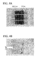
FIG. 3 , although the attenuation effect was exerted even inMeasurements 3 and 4 having high volume resistivity, the attenuation effect was small in a low frequency band. In contrast, in the case when the volume resistivity of the gasket seal was set to 5 Ωcm or less, as in the case ofMeasurements 1 and 2, an attenuation effect of at least 20 dB or more against electromagnetic waves was obtained over the entire frequency bands from 100MHz to 18 GHz. - Moreover, with respect to the structures having 5 Ωcm and 310 Ωcm in the volume resistivity of the gasket seal, salt-spray tests were carried out so as to confirm the generation of corrosion. In this test, test pieces of gasket seals having 5 Ωcm and 310 Ωcm in volume resistivity were secured onto a plate made of A2024 aluminum alloy that had been subjected to an Alodine treatment, and onto this, salt water was sprayed over 500 hours. Moreover, 168 hours after the completion of the spraying process, the presence or absence of corrosion on the aluminum plate was confirmed.
- As a result, as shown in
FIG. 4B , a portion with which the test piece having 5 Qcm in volume resistivity was made in contact had a galvanic corrosion; however, no galvanic corrosion occurred at a portion with which the test piece having 310 Qcm in volume resistivity was made in contact. - As long as the gasket seal has a volume resistivity of 300 Ωcm or more, even in the case when a bonding surface is formed as a portion to which a cabin window is secured, by carrying out a chemical conversion coating process (MIL-DTL-5541 Class 3, MIL-DTL-81706 Class 3) on the surface of an aluminum having electrical conductivity, it is possible to prevent galvanic corrosion from occurring even under moistened, humid or salt-water spraying environment because the conductive rubber material having a high resistivity is used.
- Note that the structure as described above can be changed as appropriate without departing from the gist of the present invention. A modification example is now described below. Here, in the modification example below, a structure common to the structure described above is provided with the same reference signs, and its description is omitted.
- First, the above-mentioned structures are explained by exemplifying the
cabin window 20; however, those structures may also be applied to door windows provided on doors of an aircraft and windows formed on a cockpit and side faces of the cockpit. Moreover, the present invention is also applicable to cases in which pressure seals and gaskets of openings such as doors, escape hatches or the like are made electrically conductive. -
FIG. 5 is a view that illustrates a structure in which the present invention is applied to a door window (window, closing member body) 60. As shown inFIG. 5 , in thedoor window 60, the aforementioned electromagnetic shield mesh is held between window panels (closing member panels) 61A and 61B. This structure is the same as thecabin window 20 shown inFIG. 2 . With this structure, agasket seal 65 is electrically connected to aconductive paste 64 so as to be further connected to an end of an electromagnetic shield mesh (electromagnetic shield film) 63 through theconductive paste 64, and thegasket seal 65 includes afirst seal part 51 made of a conductive rubber material having a low volume resistivity and asecond seal part 52 made of a conductive rubber material having a volume resistivity that is higher than that of thefirst seal part 51. Thus, thegasket seal 65 is electrically grounded to awindow frame 67 through a window retainer 66 (fastener member) along the entire perimeter thereof. - In the above-mentioned structures, each of the
first seal part 51 and thesecond seal part 52 is formed into an integral structure with intermolecular bonding by using a thermosetting curing process; however, not limited to this, these may be formed by using a two-color injection molding process. - Moreover, in the above-mentioned structures, the
window panels - Furthermore, not limited to the application for aircrafts, the present invention may be applicable in the same manner to any case in which an attempt is made to prepare an electromagnetic shielding configuration in a closing member for use in closing an opening, and the application thereof is not intended to be limited. For example, other applications include windows and sunroofs of automobiles, monitors for electronic apparatuses, lens protection filters for various cameras, and the like.
- Besides, the structure described in the above embodiment can be selected or can be changed as appropriate to another structure without departing from the gist of the present invention.
Claims (7)
- A window of an aircraft attached to an opening formed in an airframe of the aircraft comprising:a window body;a window frame that is formed on the inside of the opening and made of a conductive material;a gasket seal that is held between an outer perimeter part of the window body and the window frame; anda fastener member that is used for securing the window body to the airframe with the gasket seal interposed therebetween,wherein the window body comprises a transparent window panel, an electromagnetic shield film that is made of a conductive material and laminated on the window panel, and the gasket seal comprises a first seal part that is made of a conductive rubber-based material and interposed between the window panel and the window frame, and a second seal part that is made of a conductive rubber-based material having a volume resistivity different from that of the first seal part, and is made in contact with the outer perimeter part of the electromagnetic shield film.
- The window of an aircraft according to Claim 2, wherein the first seal part has a volume resistivity that is smaller than the volume resistivity of the second seal part.
- The window of an aircraft according to Claim 2, wherein the first seal part has a volume resistivity in a range of 10-3 to 5 Ωcm.
- The window of an aircraft according to Claim 2 or 3, wherein the second seal part has a volume resistivity in a range of 300 to 108 Ωcm.
- The window of an aircraft according to any one of Claims 1 to 4, wherein the first and second seal parts are formed into an integral structure by polymeric bonds between the first and second conductive rubber-based materials.
- A closing member for closing an opening formed in a product comprising:a closing member body having a panel shape; anda gasket seal that is held between an outer perimeter part of the closing member body and the opening; anda fastener member that is used for securing the closing member body to the opening of the product with the gasket seal interposed therebetween,wherein the closing member body comprises a closing member panel having a panel shape and an electromagnetic shield film that is made of a conductive material and laminated on the closing member panel,the gasket seal comprises a first seal part that is made of a first conductive rubber-based material and interposed between the closing body panel and the opening, and a second seal part that is made of a second conductive rubber-based material having a volume resistivity different from that of the first seal part, and is made in contact with the outer perimeter part of the electromagnetic shield film.
- A gasket seal to be held between an opening formed in a product and a closing member for use in closing the opening comprising:a first seal part that is made of a first conductive rubber-based material and is to be provided on one of surfaces of the closing member, and a second seal part that is made of a second conductive rubber-based material having a volume resistivity different from that of the first seal part, and is to be provided on the other surface of the closing member.
Applications Claiming Priority (1)
| Application Number | Priority Date | Filing Date | Title |
|---|---|---|---|
| JP2011200692A JP5060647B1 (en) | 2011-09-14 | 2011-09-14 | Aircraft windows, opening closures, gasket seals |
Publications (2)
| Publication Number | Publication Date |
|---|---|
| EP2570342A1 true EP2570342A1 (en) | 2013-03-20 |
| EP2570342B1 EP2570342B1 (en) | 2015-09-09 |
Family
ID=46603680
Family Applications (1)
| Application Number | Title | Priority Date | Filing Date |
|---|---|---|---|
| EP12178442.5A Active EP2570342B1 (en) | 2011-09-14 | 2012-07-30 | Aircraft window |
Country Status (3)
| Country | Link |
|---|---|
| US (1) | US8998140B2 (en) |
| EP (1) | EP2570342B1 (en) |
| JP (1) | JP5060647B1 (en) |
Cited By (1)
| Publication number | Priority date | Publication date | Assignee | Title |
|---|---|---|---|---|
| EP2910464A1 (en) * | 2014-02-24 | 2015-08-26 | Bell Helicopter Textron Inc. | Strapped windshield assembly for rotorcraft |
Families Citing this family (22)
| Publication number | Priority date | Publication date | Assignee | Title |
|---|---|---|---|---|
| US9221533B1 (en) * | 2011-10-24 | 2015-12-29 | The Boeing Company | Removable window system for space vehicles |
| US9994380B1 (en) | 2011-11-30 | 2018-06-12 | Western Digital Technologies, Inc. | Ruggedized enclosure for data storage device |
| USD795874S1 (en) | 2011-11-30 | 2017-08-29 | Western Digital Technologies, Inc. | Ruggedized enclosure for a data storage device |
| US9892762B1 (en) * | 2011-11-30 | 2018-02-13 | Western Digital Technologies, Inc. | Self retaining elastomeric seal |
| US9694896B1 (en) * | 2013-01-03 | 2017-07-04 | The Boeing Company | Airplane window having infrared heat reflection capability |
| CN104161329B (en) * | 2013-05-16 | 2016-02-03 | 一禾科技发展(上海)有限公司 | Suit face-port fastening structure and fastening method thereof |
| CN103291184B (en) * | 2013-05-16 | 2016-06-01 | 一禾科技发展(上海)有限公司 | Aircarrier aircraft window body Transparent Parts fastening structure and fastening method thereof |
| US9403590B2 (en) * | 2013-07-26 | 2016-08-02 | Gentex Corporation | Electro-optic window assembly EMI shield |
| JP6190216B2 (en) * | 2013-08-30 | 2017-08-30 | 三菱航空機株式会社 | Aircraft windows and opening closure members |
| US10052817B2 (en) | 2014-07-15 | 2018-08-21 | The Patent Well LLC | Polyurea perimeter seal for an aircraft antenna or other aircraft part |
| WO2016011025A1 (en) * | 2014-07-15 | 2016-01-21 | Aviation Devices & Electronic Components, L.L.C. | Polyurea perimeter seal for an aircraft antenna or other aircraft part |
| JP2016132340A (en) * | 2015-01-19 | 2016-07-25 | 三菱航空機株式会社 | Aircraft and transport machine |
| JP2016132341A (en) * | 2015-01-19 | 2016-07-25 | 三菱航空機株式会社 | Aircraft and transport machine |
| CA2981852A1 (en) * | 2015-04-08 | 2016-10-13 | Aviation Devices & Electronic Components, L.L.C. | A metal mesh with a low electrical resistance conversion coating for use with aircraft structures |
| DE102015120785A1 (en) * | 2015-11-30 | 2017-06-01 | Airbus Operations Gmbh | Method for producing a vehicle cabin part |
| CN107284196B (en) * | 2017-05-16 | 2019-10-15 | 北京航天发射技术研究所 | An observation window for a missile launching vehicle |
| FR3074320A1 (en) * | 2017-11-30 | 2019-05-31 | Airbus Operations | SYSTEM AND METHOD FOR AUTOMATED DETECTION OF LEAK NOISE IN AN AIRCRAFT |
| US12599184B2 (en) | 2021-01-06 | 2026-04-14 | Unitech Services Group, Inc. | Personal protective equipment ensemble made up of a launderable hood and an air dispersion protective face shield assembly |
| CN112960136B (en) * | 2021-02-08 | 2023-02-03 | 中国商用飞机有限责任公司 | Plugging device, aircraft window and plugging method thereof |
| EP4321427A1 (en) * | 2022-08-10 | 2024-02-14 | Airbus Operations GmbH | A window mounting structure for snap and click mounting of a window assembly of an aircraft |
| KR102752300B1 (en) * | 2022-09-07 | 2025-01-10 | 한국항공우주산업 주식회사 | A transparent body assembly for aircraft and method for discharging charge and/or electromagnetic wave remained thereof |
| CN117637237B (en) * | 2024-01-24 | 2024-04-26 | 北京泰派斯特电子技术有限公司 | A two-color metal skeleton composite conductive rubber |
Citations (6)
| Publication number | Priority date | Publication date | Assignee | Title |
|---|---|---|---|---|
| EP0303349A2 (en) * | 1987-08-13 | 1989-02-15 | W.L. Gore & Associates, Inc. | A canopy seal |
| US5277384A (en) * | 1991-11-04 | 1994-01-11 | Texstar, Inc. | Transparency quick seal system |
| JP2003523911A (en) | 1999-04-28 | 2003-08-12 | サン−ゴバン グラス フランス | Insulating glazing with electromagnetic shielding, especially aircraft windows |
| US20050039936A1 (en) * | 2000-03-31 | 2005-02-24 | Matsushita Electric Industrial Co., Ltd. | Electromagnetic wave shielding window, manufacturing apparatus having the same, transport system having the same, building construction having the same, and electromagnetic wave shielding method |
| US20070137117A1 (en) | 2005-12-02 | 2007-06-21 | Carlson Ryan L | Conductive gasket apparatus and method |
| US20080308677A1 (en) | 2007-06-18 | 2008-12-18 | Kirchoff Kenneth P | Radio frequency shielding apparatus system and method |
Family Cites Families (16)
| Publication number | Priority date | Publication date | Assignee | Title |
|---|---|---|---|---|
| US3592479A (en) * | 1969-03-05 | 1971-07-13 | Gits Bros Mfg Co | Shaft seal |
| US4780575A (en) * | 1987-05-14 | 1988-10-25 | Flavin John W | Electrically conductive elastomer composition |
| US4968854A (en) * | 1988-11-10 | 1990-11-06 | Vanguard Products Corporation | Dual elastomer gasket shield for electronic equipment |
| TW221837B (en) * | 1990-12-28 | 1994-03-21 | Shinetsu Chem Ind Co | |
| US5524908A (en) * | 1994-09-14 | 1996-06-11 | W. L. Gore & Associates | Multi-layer EMI/RFI gasket shield |
| DE4441345C2 (en) * | 1994-11-21 | 1997-12-04 | Bonne Andreas Dipl Ing | Sealing profile with metallic decor |
| US7376603B1 (en) * | 1997-08-19 | 2008-05-20 | Fair Isaac Corporation | Method and system for evaluating customers of a financial institution using customer relationship value tags |
| WO2000036895A2 (en) * | 1998-12-15 | 2000-06-22 | Vanguard Products Corporation | Electromagnetic interference shielding device |
| JP2000286591A (en) * | 1999-03-30 | 2000-10-13 | Asahi Glass Co Ltd | Electromagnetic shielding window glass |
| US6787221B2 (en) * | 2000-03-24 | 2004-09-07 | Chemque Incorporated | Co-dispensed compositions for gaskets and other objects |
| DE20104747U1 (en) * | 2001-03-20 | 2002-05-02 | Meteor Gummiwerke K. H. Bädje GmbH & Co, 31167 Bockenem | Gap sealing arrangement |
| WO2004076216A2 (en) * | 2003-02-27 | 2004-09-10 | Sierracin/Sylmar Corporation | Window frame/seal assembly and method of forming the same |
| PL1646813T3 (en) * | 2003-07-23 | 2013-09-30 | Ppg Ind Ohio Inc | Composite seal and window assembly |
| WO2008152934A1 (en) * | 2007-06-11 | 2008-12-18 | Fuji Polymer Industries Co., Ltd. | Metal-integral conductive rubber component |
| US20100078897A1 (en) * | 2008-07-24 | 2010-04-01 | Mcpeek Jr David A | Multiple component gasket |
| JP5492647B2 (en) * | 2010-04-19 | 2014-05-14 | 三菱航空機株式会社 | Aircraft cockpit window with electromagnetic shield, aircraft |
-
2011
- 2011-09-14 JP JP2011200692A patent/JP5060647B1/en active Active
-
2012
- 2012-07-27 US US13/560,388 patent/US8998140B2/en active Active
- 2012-07-30 EP EP12178442.5A patent/EP2570342B1/en active Active
Patent Citations (7)
| Publication number | Priority date | Publication date | Assignee | Title |
|---|---|---|---|---|
| EP0303349A2 (en) * | 1987-08-13 | 1989-02-15 | W.L. Gore & Associates, Inc. | A canopy seal |
| US5277384A (en) * | 1991-11-04 | 1994-01-11 | Texstar, Inc. | Transparency quick seal system |
| JP2003523911A (en) | 1999-04-28 | 2003-08-12 | サン−ゴバン グラス フランス | Insulating glazing with electromagnetic shielding, especially aircraft windows |
| US20050039936A1 (en) * | 2000-03-31 | 2005-02-24 | Matsushita Electric Industrial Co., Ltd. | Electromagnetic wave shielding window, manufacturing apparatus having the same, transport system having the same, building construction having the same, and electromagnetic wave shielding method |
| US20070137117A1 (en) | 2005-12-02 | 2007-06-21 | Carlson Ryan L | Conductive gasket apparatus and method |
| US7913385B2 (en) | 2005-12-02 | 2011-03-29 | The Boeing Company | Method of attenuating electromagnetic energy |
| US20080308677A1 (en) | 2007-06-18 | 2008-12-18 | Kirchoff Kenneth P | Radio frequency shielding apparatus system and method |
Cited By (3)
| Publication number | Priority date | Publication date | Assignee | Title |
|---|---|---|---|---|
| EP2910464A1 (en) * | 2014-02-24 | 2015-08-26 | Bell Helicopter Textron Inc. | Strapped windshield assembly for rotorcraft |
| US9550580B2 (en) | 2014-02-24 | 2017-01-24 | Bell Helicopter Textron Inc. | Strapped windshield assembly for rotorcraft |
| US9994300B2 (en) | 2014-02-24 | 2018-06-12 | Bell Helicopter Textron Inc. | Strapped windshield assembly for rotorcraft |
Also Published As
| Publication number | Publication date |
|---|---|
| US8998140B2 (en) | 2015-04-07 |
| JP2013060136A (en) | 2013-04-04 |
| US20130062468A1 (en) | 2013-03-14 |
| EP2570342B1 (en) | 2015-09-09 |
| JP5060647B1 (en) | 2012-10-31 |
Similar Documents
| Publication | Publication Date | Title |
|---|---|---|
| EP2570342B1 (en) | Aircraft window | |
| US9415854B2 (en) | Aircraft window and aircraft having an electromagnetic shield | |
| US9777838B2 (en) | Gasket seal, door of aircraft, seal structure for opening portion of aircraft, and aircraft | |
| CN102574572B (en) | Cockpit windows of aircraft with electromagnetic shielding, aircraft | |
| US10337236B2 (en) | Aircraft window assembly including an electromagnetic shield, a closing member including an electromagnetic shielding property, and an aircraft including an improved electromagnetic shield | |
| US9598166B2 (en) | Window of an aircraft with an electromagnetic shield | |
| EP2825799A1 (en) | Deflectable conductive gasket with environmental seal | |
| US20140097018A1 (en) | Electromagnetic shielded aircraft passenger window | |
| Yong-Sheng et al. | Research on strong electromagnetic protection technology of radar vehicle cockpit | |
| EP2906466B1 (en) | Infrared light enabled and electromagnetic shielding aircraft window | |
| Jung et al. | Study on aircraft HIRF protection design and certification process | |
| DE102024114333A1 (en) | WAVEGUARD RADAR WITH REMOVABLE ULTRA-THIN RADOM | |
| Hoad | Hoad, Richard; Wraight, Anthony; QinetiQ, Hampshire, UK | |
| Carlson | An Overview: Corrosion concerns in EMI shielding of electronics | |
| CN111319432A (en) | Electromagnetic protection method for window of radar vehicle cockpit and window | |
| VOLPE | Graphite/Epoxy Laminates | |
| HK1192608B (en) | Equipment for the reduction of the radar marking for aircrafts |
Legal Events
| Date | Code | Title | Description |
|---|---|---|---|
| PUAI | Public reference made under article 153(3) epc to a published international application that has entered the european phase |
Free format text: ORIGINAL CODE: 0009012 |
|
| 17P | Request for examination filed |
Effective date: 20120730 |
|
| AK | Designated contracting states |
Kind code of ref document: A1 Designated state(s): AL AT BE BG CH CY CZ DE DK EE ES FI FR GB GR HR HU IE IS IT LI LT LU LV MC MK MT NL NO PL PT RO RS SE SI SK SM TR |
|
| AX | Request for extension of the european patent |
Extension state: BA ME |
|
| 17Q | First examination report despatched |
Effective date: 20130628 |
|
| GRAP | Despatch of communication of intention to grant a patent |
Free format text: ORIGINAL CODE: EPIDOSNIGR1 |
|
| INTG | Intention to grant announced |
Effective date: 20150529 |
|
| GRAS | Grant fee paid |
Free format text: ORIGINAL CODE: EPIDOSNIGR3 |
|
| GRAA | (expected) grant |
Free format text: ORIGINAL CODE: 0009210 |
|
| AK | Designated contracting states |
Kind code of ref document: B1 Designated state(s): AL AT BE BG CH CY CZ DE DK EE ES FI FR GB GR HR HU IE IS IT LI LT LU LV MC MK MT NL NO PL PT RO RS SE SI SK SM TR |
|
| REG | Reference to a national code |
Ref country code: GB Ref legal event code: FG4D |
|
| REG | Reference to a national code |
Ref country code: AT Ref legal event code: REF Ref document number: 747895 Country of ref document: AT Kind code of ref document: T Effective date: 20150915 Ref country code: CH Ref legal event code: EP |
|
| REG | Reference to a national code |
Ref country code: IE Ref legal event code: FG4D |
|
| REG | Reference to a national code |
Ref country code: DE Ref legal event code: R096 Ref document number: 602012010266 Country of ref document: DE |
|
| REG | Reference to a national code |
Ref country code: NL Ref legal event code: MP Effective date: 20150909 |
|
| PG25 | Lapsed in a contracting state [announced via postgrant information from national office to epo] |
Ref country code: NO Free format text: LAPSE BECAUSE OF FAILURE TO SUBMIT A TRANSLATION OF THE DESCRIPTION OR TO PAY THE FEE WITHIN THE PRESCRIBED TIME-LIMIT Effective date: 20151209 Ref country code: FI Free format text: LAPSE BECAUSE OF FAILURE TO SUBMIT A TRANSLATION OF THE DESCRIPTION OR TO PAY THE FEE WITHIN THE PRESCRIBED TIME-LIMIT Effective date: 20150909 Ref country code: GR Free format text: LAPSE BECAUSE OF FAILURE TO SUBMIT A TRANSLATION OF THE DESCRIPTION OR TO PAY THE FEE WITHIN THE PRESCRIBED TIME-LIMIT Effective date: 20151210 Ref country code: LT Free format text: LAPSE BECAUSE OF FAILURE TO SUBMIT A TRANSLATION OF THE DESCRIPTION OR TO PAY THE FEE WITHIN THE PRESCRIBED TIME-LIMIT Effective date: 20150909 Ref country code: LV Free format text: LAPSE BECAUSE OF FAILURE TO SUBMIT A TRANSLATION OF THE DESCRIPTION OR TO PAY THE FEE WITHIN THE PRESCRIBED TIME-LIMIT Effective date: 20150909 |
|
| REG | Reference to a national code |
Ref country code: LT Ref legal event code: MG4D |
|
| REG | Reference to a national code |
Ref country code: AT Ref legal event code: MK05 Ref document number: 747895 Country of ref document: AT Kind code of ref document: T Effective date: 20150909 |
|
| PG25 | Lapsed in a contracting state [announced via postgrant information from national office to epo] |
Ref country code: SE Free format text: LAPSE BECAUSE OF FAILURE TO SUBMIT A TRANSLATION OF THE DESCRIPTION OR TO PAY THE FEE WITHIN THE PRESCRIBED TIME-LIMIT Effective date: 20150909 Ref country code: HR Free format text: LAPSE BECAUSE OF FAILURE TO SUBMIT A TRANSLATION OF THE DESCRIPTION OR TO PAY THE FEE WITHIN THE PRESCRIBED TIME-LIMIT Effective date: 20150909 Ref country code: RS Free format text: LAPSE BECAUSE OF FAILURE TO SUBMIT A TRANSLATION OF THE DESCRIPTION OR TO PAY THE FEE WITHIN THE PRESCRIBED TIME-LIMIT Effective date: 20150909 Ref country code: ES Free format text: LAPSE BECAUSE OF FAILURE TO SUBMIT A TRANSLATION OF THE DESCRIPTION OR TO PAY THE FEE WITHIN THE PRESCRIBED TIME-LIMIT Effective date: 20150909 |
|
| PG25 | Lapsed in a contracting state [announced via postgrant information from national office to epo] |
Ref country code: NL Free format text: LAPSE BECAUSE OF FAILURE TO SUBMIT A TRANSLATION OF THE DESCRIPTION OR TO PAY THE FEE WITHIN THE PRESCRIBED TIME-LIMIT Effective date: 20150909 |
|
| PG25 | Lapsed in a contracting state [announced via postgrant information from national office to epo] |
Ref country code: SK Free format text: LAPSE BECAUSE OF FAILURE TO SUBMIT A TRANSLATION OF THE DESCRIPTION OR TO PAY THE FEE WITHIN THE PRESCRIBED TIME-LIMIT Effective date: 20150909 Ref country code: EE Free format text: LAPSE BECAUSE OF FAILURE TO SUBMIT A TRANSLATION OF THE DESCRIPTION OR TO PAY THE FEE WITHIN THE PRESCRIBED TIME-LIMIT Effective date: 20150909 Ref country code: IS Free format text: LAPSE BECAUSE OF FAILURE TO SUBMIT A TRANSLATION OF THE DESCRIPTION OR TO PAY THE FEE WITHIN THE PRESCRIBED TIME-LIMIT Effective date: 20160109 Ref country code: IT Free format text: LAPSE BECAUSE OF FAILURE TO SUBMIT A TRANSLATION OF THE DESCRIPTION OR TO PAY THE FEE WITHIN THE PRESCRIBED TIME-LIMIT Effective date: 20150909 Ref country code: CZ Free format text: LAPSE BECAUSE OF FAILURE TO SUBMIT A TRANSLATION OF THE DESCRIPTION OR TO PAY THE FEE WITHIN THE PRESCRIBED TIME-LIMIT Effective date: 20150909 |
|
| PG25 | Lapsed in a contracting state [announced via postgrant information from national office to epo] |
Ref country code: RO Free format text: LAPSE BECAUSE OF FAILURE TO SUBMIT A TRANSLATION OF THE DESCRIPTION OR TO PAY THE FEE WITHIN THE PRESCRIBED TIME-LIMIT Effective date: 20150909 Ref country code: PL Free format text: LAPSE BECAUSE OF FAILURE TO SUBMIT A TRANSLATION OF THE DESCRIPTION OR TO PAY THE FEE WITHIN THE PRESCRIBED TIME-LIMIT Effective date: 20150909 Ref country code: AT Free format text: LAPSE BECAUSE OF FAILURE TO SUBMIT A TRANSLATION OF THE DESCRIPTION OR TO PAY THE FEE WITHIN THE PRESCRIBED TIME-LIMIT Effective date: 20150909 Ref country code: PT Free format text: LAPSE BECAUSE OF FAILURE TO SUBMIT A TRANSLATION OF THE DESCRIPTION OR TO PAY THE FEE WITHIN THE PRESCRIBED TIME-LIMIT Effective date: 20160111 |
|
| REG | Reference to a national code |
Ref country code: DE Ref legal event code: R097 Ref document number: 602012010266 Country of ref document: DE |
|
| REG | Reference to a national code |
Ref country code: FR Ref legal event code: PLFP Year of fee payment: 5 |
|
| PLBE | No opposition filed within time limit |
Free format text: ORIGINAL CODE: 0009261 |
|
| STAA | Information on the status of an ep patent application or granted ep patent |
Free format text: STATUS: NO OPPOSITION FILED WITHIN TIME LIMIT |
|
| 26N | No opposition filed |
Effective date: 20160610 |
|
| PG25 | Lapsed in a contracting state [announced via postgrant information from national office to epo] |
Ref country code: SI Free format text: LAPSE BECAUSE OF FAILURE TO SUBMIT A TRANSLATION OF THE DESCRIPTION OR TO PAY THE FEE WITHIN THE PRESCRIBED TIME-LIMIT Effective date: 20150909 Ref country code: DK Free format text: LAPSE BECAUSE OF FAILURE TO SUBMIT A TRANSLATION OF THE DESCRIPTION OR TO PAY THE FEE WITHIN THE PRESCRIBED TIME-LIMIT Effective date: 20150909 |
|
| PG25 | Lapsed in a contracting state [announced via postgrant information from national office to epo] |
Ref country code: BE Free format text: LAPSE BECAUSE OF FAILURE TO SUBMIT A TRANSLATION OF THE DESCRIPTION OR TO PAY THE FEE WITHIN THE PRESCRIBED TIME-LIMIT Effective date: 20150909 |
|
| REG | Reference to a national code |
Ref country code: CH Ref legal event code: PL |
|
| PG25 | Lapsed in a contracting state [announced via postgrant information from national office to epo] |
Ref country code: MC Free format text: LAPSE BECAUSE OF FAILURE TO SUBMIT A TRANSLATION OF THE DESCRIPTION OR TO PAY THE FEE WITHIN THE PRESCRIBED TIME-LIMIT Effective date: 20150909 |
|
| PG25 | Lapsed in a contracting state [announced via postgrant information from national office to epo] |
Ref country code: LI Free format text: LAPSE BECAUSE OF NON-PAYMENT OF DUE FEES Effective date: 20160731 Ref country code: CH Free format text: LAPSE BECAUSE OF NON-PAYMENT OF DUE FEES Effective date: 20160731 |
|
| REG | Reference to a national code |
Ref country code: IE Ref legal event code: MM4A |
|
| REG | Reference to a national code |
Ref country code: FR Ref legal event code: PLFP Year of fee payment: 6 |
|
| PG25 | Lapsed in a contracting state [announced via postgrant information from national office to epo] |
Ref country code: IE Free format text: LAPSE BECAUSE OF NON-PAYMENT OF DUE FEES Effective date: 20160730 |
|
| PG25 | Lapsed in a contracting state [announced via postgrant information from national office to epo] |
Ref country code: LU Free format text: LAPSE BECAUSE OF NON-PAYMENT OF DUE FEES Effective date: 20160730 |
|
| PG25 | Lapsed in a contracting state [announced via postgrant information from national office to epo] |
Ref country code: CY Free format text: LAPSE BECAUSE OF FAILURE TO SUBMIT A TRANSLATION OF THE DESCRIPTION OR TO PAY THE FEE WITHIN THE PRESCRIBED TIME-LIMIT Effective date: 20150909 Ref country code: HU Free format text: LAPSE BECAUSE OF FAILURE TO SUBMIT A TRANSLATION OF THE DESCRIPTION OR TO PAY THE FEE WITHIN THE PRESCRIBED TIME-LIMIT; INVALID AB INITIO Effective date: 20120730 Ref country code: SM Free format text: LAPSE BECAUSE OF FAILURE TO SUBMIT A TRANSLATION OF THE DESCRIPTION OR TO PAY THE FEE WITHIN THE PRESCRIBED TIME-LIMIT Effective date: 20150909 |
|
| REG | Reference to a national code |
Ref country code: FR Ref legal event code: PLFP Year of fee payment: 7 |
|
| PG25 | Lapsed in a contracting state [announced via postgrant information from national office to epo] |
Ref country code: MK Free format text: LAPSE BECAUSE OF FAILURE TO SUBMIT A TRANSLATION OF THE DESCRIPTION OR TO PAY THE FEE WITHIN THE PRESCRIBED TIME-LIMIT Effective date: 20150909 Ref country code: TR Free format text: LAPSE BECAUSE OF FAILURE TO SUBMIT A TRANSLATION OF THE DESCRIPTION OR TO PAY THE FEE WITHIN THE PRESCRIBED TIME-LIMIT Effective date: 20150909 Ref country code: MT Free format text: LAPSE BECAUSE OF NON-PAYMENT OF DUE FEES Effective date: 20160731 |
|
| PG25 | Lapsed in a contracting state [announced via postgrant information from national office to epo] |
Ref country code: BG Free format text: LAPSE BECAUSE OF FAILURE TO SUBMIT A TRANSLATION OF THE DESCRIPTION OR TO PAY THE FEE WITHIN THE PRESCRIBED TIME-LIMIT Effective date: 20150909 |
|
| PG25 | Lapsed in a contracting state [announced via postgrant information from national office to epo] |
Ref country code: AL Free format text: LAPSE BECAUSE OF FAILURE TO SUBMIT A TRANSLATION OF THE DESCRIPTION OR TO PAY THE FEE WITHIN THE PRESCRIBED TIME-LIMIT Effective date: 20150909 |
|
| PGFP | Annual fee paid to national office [announced via postgrant information from national office to epo] |
Ref country code: FR Payment date: 20230620 Year of fee payment: 12 |
|
| PGFP | Annual fee paid to national office [announced via postgrant information from national office to epo] |
Ref country code: DE Payment date: 20230607 Year of fee payment: 12 |
|
| REG | Reference to a national code |
Ref country code: GB Ref legal event code: 732E Free format text: REGISTERED BETWEEN 20240725 AND 20240731 |
|
| REG | Reference to a national code |
Ref country code: DE Ref legal event code: R119 Ref document number: 602012010266 Country of ref document: DE |
|
| PG25 | Lapsed in a contracting state [announced via postgrant information from national office to epo] |
Ref country code: DE Free format text: LAPSE BECAUSE OF NON-PAYMENT OF DUE FEES Effective date: 20250201 |
|
| PG25 | Lapsed in a contracting state [announced via postgrant information from national office to epo] |
Ref country code: FR Free format text: LAPSE BECAUSE OF NON-PAYMENT OF DUE FEES Effective date: 20240731 |
|
| PGFP | Annual fee paid to national office [announced via postgrant information from national office to epo] |
Ref country code: GB Payment date: 20250605 Year of fee payment: 14 |