EP2570286A1 - Meter device - Google Patents
Meter device Download PDFInfo
- Publication number
- EP2570286A1 EP2570286A1 EP11780469A EP11780469A EP2570286A1 EP 2570286 A1 EP2570286 A1 EP 2570286A1 EP 11780469 A EP11780469 A EP 11780469A EP 11780469 A EP11780469 A EP 11780469A EP 2570286 A1 EP2570286 A1 EP 2570286A1
- Authority
- EP
- European Patent Office
- Prior art keywords
- display
- turn
- indication lamp
- arrow
- lamp
- Prior art date
- Legal status (The legal status is an assumption and is not a legal conclusion. Google has not performed a legal analysis and makes no representation as to the accuracy of the status listed.)
- Withdrawn
Links
Images


Classifications
-
- B—PERFORMING OPERATIONS; TRANSPORTING
- B60—VEHICLES IN GENERAL
- B60Q—ARRANGEMENT OF SIGNALLING OR LIGHTING DEVICES, THE MOUNTING OR SUPPORTING THEREOF OR CIRCUITS THEREFOR, FOR VEHICLES IN GENERAL
- B60Q1/00—Arrangement of optical signalling or lighting devices, the mounting or supporting thereof or circuits therefor
-
- B—PERFORMING OPERATIONS; TRANSPORTING
- B60—VEHICLES IN GENERAL
- B60K—ARRANGEMENT OR MOUNTING OF PROPULSION UNITS OR OF TRANSMISSIONS IN VEHICLES; ARRANGEMENT OR MOUNTING OF PLURAL DIVERSE PRIME-MOVERS IN VEHICLES; AUXILIARY DRIVES FOR VEHICLES; INSTRUMENTATION OR DASHBOARDS FOR VEHICLES; ARRANGEMENTS IN CONNECTION WITH COOLING, AIR INTAKE, GAS EXHAUST OR FUEL SUPPLY OF PROPULSION UNITS IN VEHICLES
- B60K35/00—Instruments specially adapted for vehicles; Arrangement of instruments in or on vehicles
- B60K35/20—Output arrangements, i.e. from vehicle to user, associated with vehicle functions or specially adapted therefor
- B60K35/21—Output arrangements, i.e. from vehicle to user, associated with vehicle functions or specially adapted therefor using visual output, e.g. blinking lights or matrix displays
- B60K35/215—Output arrangements, i.e. from vehicle to user, associated with vehicle functions or specially adapted therefor using visual output, e.g. blinking lights or matrix displays characterised by the combination of multiple visual outputs, e.g. combined instruments with analogue meters and additional displays
-
- B—PERFORMING OPERATIONS; TRANSPORTING
- B60—VEHICLES IN GENERAL
- B60K—ARRANGEMENT OR MOUNTING OF PROPULSION UNITS OR OF TRANSMISSIONS IN VEHICLES; ARRANGEMENT OR MOUNTING OF PLURAL DIVERSE PRIME-MOVERS IN VEHICLES; AUXILIARY DRIVES FOR VEHICLES; INSTRUMENTATION OR DASHBOARDS FOR VEHICLES; ARRANGEMENTS IN CONNECTION WITH COOLING, AIR INTAKE, GAS EXHAUST OR FUEL SUPPLY OF PROPULSION UNITS IN VEHICLES
- B60K35/00—Instruments specially adapted for vehicles; Arrangement of instruments in or on vehicles
- B60K35/20—Output arrangements, i.e. from vehicle to user, associated with vehicle functions or specially adapted therefor
- B60K35/21—Output arrangements, i.e. from vehicle to user, associated with vehicle functions or specially adapted therefor using visual output, e.g. blinking lights or matrix displays
- B60K35/22—Display screens
-
- B—PERFORMING OPERATIONS; TRANSPORTING
- B60—VEHICLES IN GENERAL
- B60K—ARRANGEMENT OR MOUNTING OF PROPULSION UNITS OR OF TRANSMISSIONS IN VEHICLES; ARRANGEMENT OR MOUNTING OF PLURAL DIVERSE PRIME-MOVERS IN VEHICLES; AUXILIARY DRIVES FOR VEHICLES; INSTRUMENTATION OR DASHBOARDS FOR VEHICLES; ARRANGEMENTS IN CONNECTION WITH COOLING, AIR INTAKE, GAS EXHAUST OR FUEL SUPPLY OF PROPULSION UNITS IN VEHICLES
- B60K35/00—Instruments specially adapted for vehicles; Arrangement of instruments in or on vehicles
- B60K35/20—Output arrangements, i.e. from vehicle to user, associated with vehicle functions or specially adapted therefor
- B60K35/28—Output arrangements, i.e. from vehicle to user, associated with vehicle functions or specially adapted therefor characterised by the type of the output information, e.g. video entertainment or vehicle dynamics information; characterised by the purpose of the output information, e.g. for attracting the attention of the driver
-
- B—PERFORMING OPERATIONS; TRANSPORTING
- B60—VEHICLES IN GENERAL
- B60K—ARRANGEMENT OR MOUNTING OF PROPULSION UNITS OR OF TRANSMISSIONS IN VEHICLES; ARRANGEMENT OR MOUNTING OF PLURAL DIVERSE PRIME-MOVERS IN VEHICLES; AUXILIARY DRIVES FOR VEHICLES; INSTRUMENTATION OR DASHBOARDS FOR VEHICLES; ARRANGEMENTS IN CONNECTION WITH COOLING, AIR INTAKE, GAS EXHAUST OR FUEL SUPPLY OF PROPULSION UNITS IN VEHICLES
- B60K37/00—Dashboards
- B60K37/20—Dashboard panels
-
- B—PERFORMING OPERATIONS; TRANSPORTING
- B60—VEHICLES IN GENERAL
- B60K—ARRANGEMENT OR MOUNTING OF PROPULSION UNITS OR OF TRANSMISSIONS IN VEHICLES; ARRANGEMENT OR MOUNTING OF PLURAL DIVERSE PRIME-MOVERS IN VEHICLES; AUXILIARY DRIVES FOR VEHICLES; INSTRUMENTATION OR DASHBOARDS FOR VEHICLES; ARRANGEMENTS IN CONNECTION WITH COOLING, AIR INTAKE, GAS EXHAUST OR FUEL SUPPLY OF PROPULSION UNITS IN VEHICLES
- B60K2360/00—Indexing scheme associated with groups B60K35/00 or B60K37/00 relating to details of instruments or dashboards
- B60K2360/1523—Matrix displays
-
- B—PERFORMING OPERATIONS; TRANSPORTING
- B60—VEHICLES IN GENERAL
- B60K—ARRANGEMENT OR MOUNTING OF PROPULSION UNITS OR OF TRANSMISSIONS IN VEHICLES; ARRANGEMENT OR MOUNTING OF PLURAL DIVERSE PRIME-MOVERS IN VEHICLES; AUXILIARY DRIVES FOR VEHICLES; INSTRUMENTATION OR DASHBOARDS FOR VEHICLES; ARRANGEMENTS IN CONNECTION WITH COOLING, AIR INTAKE, GAS EXHAUST OR FUEL SUPPLY OF PROPULSION UNITS IN VEHICLES
- B60K2360/00—Indexing scheme associated with groups B60K35/00 or B60K37/00 relating to details of instruments or dashboards
- B60K2360/18—Information management
- B60K2360/184—Displaying the same information on different displays
-
- B—PERFORMING OPERATIONS; TRANSPORTING
- B60—VEHICLES IN GENERAL
- B60K—ARRANGEMENT OR MOUNTING OF PROPULSION UNITS OR OF TRANSMISSIONS IN VEHICLES; ARRANGEMENT OR MOUNTING OF PLURAL DIVERSE PRIME-MOVERS IN VEHICLES; AUXILIARY DRIVES FOR VEHICLES; INSTRUMENTATION OR DASHBOARDS FOR VEHICLES; ARRANGEMENTS IN CONNECTION WITH COOLING, AIR INTAKE, GAS EXHAUST OR FUEL SUPPLY OF PROPULSION UNITS IN VEHICLES
- B60K2360/00—Indexing scheme associated with groups B60K35/00 or B60K37/00 relating to details of instruments or dashboards
- B60K2360/18—Information management
- B60K2360/186—Displaying information according to relevancy
- B60K2360/1868—Displaying information according to relevancy according to driving situations
-
- B—PERFORMING OPERATIONS; TRANSPORTING
- B60—VEHICLES IN GENERAL
- B60K—ARRANGEMENT OR MOUNTING OF PROPULSION UNITS OR OF TRANSMISSIONS IN VEHICLES; ARRANGEMENT OR MOUNTING OF PLURAL DIVERSE PRIME-MOVERS IN VEHICLES; AUXILIARY DRIVES FOR VEHICLES; INSTRUMENTATION OR DASHBOARDS FOR VEHICLES; ARRANGEMENTS IN CONNECTION WITH COOLING, AIR INTAKE, GAS EXHAUST OR FUEL SUPPLY OF PROPULSION UNITS IN VEHICLES
- B60K2360/00—Indexing scheme associated with groups B60K35/00 or B60K37/00 relating to details of instruments or dashboards
- B60K2360/18—Information management
- B60K2360/191—Highlight information
-
- B—PERFORMING OPERATIONS; TRANSPORTING
- B60—VEHICLES IN GENERAL
- B60K—ARRANGEMENT OR MOUNTING OF PROPULSION UNITS OR OF TRANSMISSIONS IN VEHICLES; ARRANGEMENT OR MOUNTING OF PLURAL DIVERSE PRIME-MOVERS IN VEHICLES; AUXILIARY DRIVES FOR VEHICLES; INSTRUMENTATION OR DASHBOARDS FOR VEHICLES; ARRANGEMENTS IN CONNECTION WITH COOLING, AIR INTAKE, GAS EXHAUST OR FUEL SUPPLY OF PROPULSION UNITS IN VEHICLES
- B60K35/00—Instruments specially adapted for vehicles; Arrangement of instruments in or on vehicles
- B60K35/20—Output arrangements, i.e. from vehicle to user, associated with vehicle functions or specially adapted therefor
- B60K35/28—Output arrangements, i.e. from vehicle to user, associated with vehicle functions or specially adapted therefor characterised by the type of the output information, e.g. video entertainment or vehicle dynamics information; characterised by the purpose of the output information, e.g. for attracting the attention of the driver
- B60K35/285—Output arrangements, i.e. from vehicle to user, associated with vehicle functions or specially adapted therefor characterised by the type of the output information, e.g. video entertainment or vehicle dynamics information; characterised by the purpose of the output information, e.g. for attracting the attention of the driver for improving awareness by directing driver's gaze direction or eye points
-
- B—PERFORMING OPERATIONS; TRANSPORTING
- B60—VEHICLES IN GENERAL
- B60K—ARRANGEMENT OR MOUNTING OF PROPULSION UNITS OR OF TRANSMISSIONS IN VEHICLES; ARRANGEMENT OR MOUNTING OF PLURAL DIVERSE PRIME-MOVERS IN VEHICLES; AUXILIARY DRIVES FOR VEHICLES; INSTRUMENTATION OR DASHBOARDS FOR VEHICLES; ARRANGEMENTS IN CONNECTION WITH COOLING, AIR INTAKE, GAS EXHAUST OR FUEL SUPPLY OF PROPULSION UNITS IN VEHICLES
- B60K35/00—Instruments specially adapted for vehicles; Arrangement of instruments in or on vehicles
- B60K35/20—Output arrangements, i.e. from vehicle to user, associated with vehicle functions or specially adapted therefor
- B60K35/29—Instruments characterised by the way in which information is handled, e.g. showing information on plural displays or prioritising information according to driving conditions
-
- B—PERFORMING OPERATIONS; TRANSPORTING
- B60—VEHICLES IN GENERAL
- B60K—ARRANGEMENT OR MOUNTING OF PROPULSION UNITS OR OF TRANSMISSIONS IN VEHICLES; ARRANGEMENT OR MOUNTING OF PLURAL DIVERSE PRIME-MOVERS IN VEHICLES; AUXILIARY DRIVES FOR VEHICLES; INSTRUMENTATION OR DASHBOARDS FOR VEHICLES; ARRANGEMENTS IN CONNECTION WITH COOLING, AIR INTAKE, GAS EXHAUST OR FUEL SUPPLY OF PROPULSION UNITS IN VEHICLES
- B60K35/00—Instruments specially adapted for vehicles; Arrangement of instruments in or on vehicles
- B60K35/80—Arrangements for controlling instruments
- B60K35/81—Arrangements for controlling instruments for controlling displays
Definitions
- the present invention relates to an instrument device.
- the patent document 1 discloses an instrument device that is arranged between a speed meter indicating a vehicle speed by an indicator needle and a tachometer indicating an engine speed by an indicator needle and on an instrument panel.
- Patent Document 1 Japanese Patent Application Laid-Open No. 2009-113700
- an indication lamp a turn-signal indication lamp, a high beam lamp for example
- a degree of driver's recognition of a change in a lighting state (blinking etc.) of an indication lamp becomes low compared to that of information on a display because the driver has a tendency to give his or her consciousness on an image on a display compared to an indication lamp (a turn-signal indication lamp, a high beam lamp for example) arranged on the instrument panel.
- the object of the present invention is to provide an instrument device that can improve a degree of driver's recognition to a change in a lighting state of an indication lamp.
- a design indicating an indication lamp changing a lighting state is displayed in a display image of a display.
- the driver can be easily aware of the change in the lighting state of the indication lamp due to the design displayed in the display image on the display in a case where the driver's consciousness is directed to the display.
- FIG. 1 is a front view showing a combination meter 1 of a first embodiment
- the combination meter 1 of the first embodiment is attached to be directed toward a rear side of a not-shown motor vehicle in a meter cluster provided on an instrument panel of the motor vehicle.
- a speed meter 3 and a tachometer 4 are respectively arranged at the left side and the right side of a instrument panel 2, and a display 5 is arranged between the speed meter 3 and the tachometer 4 to display picture images and others.
- a fuel gauge 6 is arranged at the left side of the speed meter 3, and a water temperature gauge 7 is arranged at the right side of the tachometer 4.
- the speed meter 3 and the tachometer 4, and the fuel gauge 6 and the water temperature gauge 7 are respectively arranged at a bilaterally symmetric position of the display 5, employing analog indicators that indicates by using an indicating needle.
- the display 5 is built in the combination meters 1, which improves safeness because time for a driver to avert his or her gaze from the front sight of the motor vehicle can be almost the same as that for the driver to read the meters.
- various warning lamps and indication lamps are arranged under each meter 3, 4, 6, 7 and the display 5. Specifically, they are a half-shut door warning lamp 8a, a seat belt warning lamp 8b, an SRS air bag warning lamp 8c, an ABS warning lamp 8d, a brake warning lamp 8e, a SLIP warning lamp 8f, an oil pressure warning lamp 8g, an engine warning lamp 8h, a charge warning lamp 8i, a VDCOFF indication lamp 8j, an A/T electronic control system warning lamp 8k, an A/T select position indication lamp 8m, and a manual mode indication lamp 8n.
- 9a indicates a reset knob of a trip meter
- 9b indicates a push knob.
- a high beam indication lamp 10 is arranged at the left side of the speed meter 3 and above the fuel gauge 6.
- left and right turn-signal indication lamps (corresponding to an indication lamp of the present invention) 11a, 11b are arranged close to the display 5 and at the bilaterally symmetric position of the display 5.
- the left turn-signal indication lamp 11a is shown as an arrow heading toward the left side
- the right turn-signal indication lamp 11b is shown as an arrow heading toward the right side. Each of them respectively notifies its operation by blinking the light.
- a display screen of the display 5 On a display screen of the display 5, information obtained by a not-shown car navigation system and information on the motor vehicle are displayed, while information on a fuel consumption, a power, a maintenance state and others may be also displayed. Further, a video picture obtained by a camera may be displayed in a case where the motor vehicle is a big size car or a van type car which are equipped with the camera monitoring both sides and the rear side of the motor vehicle.
- the display 5 is fixed on a control circuit board 13 arranged at a rear side (a front side of the motor vehicle) of the instrument panel 2, and it's display surface 5a is arranged to be headed toward a front surface side (the rear side of the motor vehicle) of the instrument panel 2 through an opening 14 formed in the instrument panel 2.
- a step is formed between the display surface 5a of the display 5 and a character panel surface 2a of the instrument panel 2, so that a driver sees the display 5 at the position deeper than (at the front side of the motor vehicle) the instrument panel 2.
- the opening 14 is closed by a finisher 15, which prevents the driver from seeing the control circuit board 13.
- stepping motors each driving the indicating needle and LEDs used for each indication and warning lamp including a stepping motor 3b driving the indicating needle 3a of the speed meter 3 and a stepping motor 4b driving the indicating needle 4a of the tachometer 4, are arranged.
- the displays of each meter 3, 4, 6, 7, each indication/warning lamp 8a to 8n, 10, 11a, 11b, and display 5 in the combination meters 1 are controlled by a control unit (corresponding to a display control means of the present invention).
- the control unit 12 mainly consists of a well-known microcomputer having a CPU, a ROM, a RAM, as SRAM, an I/O which are provided on the control circuit board 13, and bus lines, carrying out various process based on programs stored in the ROM and the RAM.
- the control unit 12 receives the various information on the motor vehicle through a CAN and the information from the navigation system, and it controls to drive the stepping motors moving the indicating needles of the meters 3, 4, 6, 7, also controlling each LED changing the lighting state of each indication/warning lamp 8a to 8n, 10, 11a, 11b and display contents of the display 5.
- the light of the left turn-signal indication lamp 11a is blinked when a left turn-signal indication switch is turned ON, while the light of the left turn-signal indication lamp 11a goes out when the left turn-signal indication switch is turned OFF.
- the light of the right turn-signal indication lamp 11b is blinked when a right turn-signal indication switch is turned ON, while the light of the right turn-signal indication lamp 11b goes out when the right turn-signal indication switch is turned OFF.
- the left and right turn-signal indication lamps 11a, 11b are blinked at the same time.
- head lamps are moved in an upward direction (a high beam state)
- the high beam indication lamp 10 is lighted
- the high beam indication lamp 10 is turned off when the head lamps are moved in a downward direction (a low beam state) or they are turned off.
- arrow images 17, 18, 19, 20 having shapes similar to those of the left and right turn-signal lamps 11a, 11b are blinked in the same period as the blinking periods of the left and right turn-signal lamps 11a, 11b in display image 16 shown on the display 5.
- a display image 21 indicating a predetermined state of the vehicle at the center of the display image 16 the arrow images 17, 18, 19, 20 are displayed at the positions of the both side of the left and right turn-signal lamps 11a, 11b, being away from the display image 21.
- the arrow images 17, 18 are displayed at an upper left corner portion of the display image 16 near the left turn-signal lamp 11a
- the arrow images 19, 20 are displayed at an upper right corner portion of the display image 16 near the right turn-signal lamp 11b.
- the arrow images 17, 18, 19, 20 are at the same positions in the upward and down ward direction and in the left and right direction as those of the left and right turn-signal lamps 11a, 11b.
- the arrow mages 17, 18, 19, 20 are arranged on the horizontal line together with the left and right turn-signal lamps 11a, 11b.
- the arrow images 17, 18 have the shapes similar to that of the left turn-signal lamp 11a, and in the same direction as that of the left turn-signal lamp 11a.
- the sizes of the left turn-signal lamp 11a, the arrow image 17, and the arrow image 18 become smaller in these orders.
- the arrow images 17, 18 have the same color (green for example) as that of the left turn-signal lamp 11a, and the brightness of the left turn-signal lamp 11a, the arrow image 17 and the arrow image 18 become lower in these orders.
- they may have the same system color and different tones instead of using the same color with different brightness.
- the tones of the left turn-signal lamp 11a, the arrow image 17 and the arrow image 18 become lower in these orders.
- the colors of the left turn-signal lamp 11a, the arrow image 17 and the arrow image 18 may have gradation.
- a relationship between the arrow images 19, 20 and the right turn-signal indication lamp 11b is the same as that in which the arrow images 17, 18 and the left turn-signal indication lamp 11a are respectively replaced by the arrow images 19, 20 and the right turn-signal indication lamp 11b in the above-described explanation, and accordingly their explanations are omitted.
- the arrow images 17, 18, 19, 20 are indicated at the same time for convenience' sake in FIG. 1 , in actual, the arrow images 17, 18 are blinked in the same period as that of the blinking of the left turn-signal indication lamp 11a, at different timing and in these orders, while the arrow images 19, 20 are blinked in the same period as that of the blinking of the right turn-signal indication lamp 11b, at different timing and in these orders.
- the arrow image 18, the arrow image 17, and the left-turn indication lamp 11a are blinked or displayed in a predetermined period in these orders.
- the arrow image 20, the arrow image 19, and the left-turn indication lamp 11b are blinked or displayed in the predetermined period in these orders. Accordingly, the arrow images 17 and 18 are not displayed at the same time, and the arrow images 19 and 20 are not displayed at the same time. In addition, any one of the arrow images 17, 18, 19, 20 is not displayed at the same time while the left-turn or right-turn indication lamp 11a, 11b is blinking.
- the display 5 is arranged at the center of the instrument panel 2 in the left and right direction to display diverse information on the vehicle such as the information obtained from a car navigation system.
- the information displayed in the images 16 on the display 5 can be displayed with many colors, decorations and others compared to the meters and the various displays/warning lamps arranged on the instrument panel 2. Accordingly, the consciousness of the driver has the tendency to be directed to the information in the display images 16 when the display image 16 is displayed on the display 5.
- the arrow images 17, 18, 19, 20 are displayed in the display image 16 displayed on the display 5, so that the consciousness of the drive who gazes the display image 16 on the display 5 can be easily directed to the blinking of the left-turn or right-turn signal indication lamp 11a, 11b.
- This enables the degree of recognition of the driver to the blinking of left-turn or right-turn signal indication lamp 11a, 11b to be improved, thereby preventing the driver from forgetting to turn off the hazard switch as described above.
- the arrow image 17, 18, 19, 20 are blinked in the same period as those of the left-turn and right-turn signal indication lamps 11a, 11b, so that the driver can have a feeling of unity in the left-turn and right-turn signal indication lamps 11a, 11b and the arrow images 17, 18, 19, 20, recognizing a relationship between the blinking displays of the arrow images 17, 18, 19, 20 and the blinking of the left-turn and right-turn signal indication lamps 11a, 11b. Therefore, the degree of recognition of the driver to the blinking of the left-turn and right-turn signal indication lamps 11a, 11b can be improved.
- the arrow images 17, 18 are designed to have an arrow shape similar to the left-turn signal indication lamp 11a and also have the same direction
- the arrow images 19, 29 are designed to have an arrow shape similar to the right-turn signal indication lamp 11b and also have the same direction. Therefore, the driver can easily image the blinking of the turn signal lamp when the driver sees the blinking displays of the arrow images 17, 18, 19, 20, and the degree of the driver's recognition to the blinking of the left-turn or right-turn signal indication lamp 11a, 11b is improved.
- the arrow images 17, 18, and 19, 20 are respectively arranged near the left-turn and right-turn signal indication lamp 11a, 11b, and they are arranged on a straight line, so that the driver can have a feeling of unity of the left-turn and right-turn signal indication lamp 11a, 11b and the arrow images 17, 18, 19, 20.
- the display 5 is arranged at the position deeper than the instrument panel 2, which might degenerate its design of appearance because the feeling of unity and continuous display of the instrument panel 2 and the display 6 are degenerated due to the step formed by the display surface 5a of the display 5 and the character panel surface 2a of the instrument panel 2.
- the arrow images 17, 18, and 19, 20 are respectively arranged near the left-turn and right-turn signal indication lamps 11a, 11b, and they are located on the straight line, and accordingly the first embodiment can provide the feeling of continuous display and unity of the display surface 5a and the character panel surface 2a, improving the design of appearance of the combination meter 1.
- the display surface 5 of the display 5 is arranged at a vehicle front side far from the eye point (the position of eyes) of the driver, for example, when the left-turn signal switch is turned on, the arrow image 18, the arrow image 17, and the left-turn signal indication lamp 11a is turned on or displayed in these orders.
- the right-turn signal switch is turned on, the arrow image 20, the arrow image 19, and the right-turn signal indication lamp 11b is turned on or displayed in these orders.
- the first embodiment can provide a stereoscopic dramatic impact having a sense of depth as if the blinking of the left-turn and right-turn signal indication lamps 11a, 11b pops up from the display surface 5a toward the character panel surface 2a.
- the arrow images 18, 20 employ the smallest arrow
- the arrow images 17, 19 employ an intermediate arrow
- the left-turn and right-turn signal indication lamps 11a, 11b employ the largest arrow, and accordingly it can emphasis the sense of depth.
- the instrument of the first embodiment can provide the effects listed below.
- the combination meter 1 equipped with the display 5 in the instrument panel 2 has the left-turn and right-turn signal indication lamps 11a, 11b arranged on the instrument panel 2, and the control unit 12 to display the arrow images 17, 18, 19, 20 that indicate the change in the lighting state (the blinking) of the indication lamps (the left-turn and right-turn signal indication lamps 11a, 11b) in the display image 16 on the display 5. Therefore, the arrow images 17, 18, 19, 20 can improve the degree of driver's recognition to the blinking of the left-turn and right-turn signal indication lamps 11a, 11b.
- the control unit 12 controls to display the arrow images 17, 18, 19, 20 in the blinking state in the same period as that of the change in the lighting state of the indication lamps. Therefore, it can provide the feeling of unity in the left-turn and right-tnrn signal indication lamps 11a, 11b and the arrow images 17, 18, 19, 20, thereby improving the degree of driver's recognition to the blinking of the left-turn and right-turn signal indication lamps 11 a, 116.
- the control unit 12 controls to display the arrow images the arrow images 17, 18, 19, 20 in shapes similar to those of the indication lamps. Therefore, the driver can easily image that the left-turn or right-turn signal indication lamps 11 a, 11b is blinking based on the blinking of the arrow images 17, 18, 19, 20.
- the indication lams are arranged near the outer circumference of the display 5, and the control unit 15 controls to display the arrow images 17, 18, 19, 20 to be displayed at the indication lamp sides apart from the center of the display image 16. Therefore, it can provide the feeling of unity or the left-turn and right-turn signal indication lamps 11a, 11b and the arrow images 17, 18, 19, 20.
- the control unit 12 controls to display the arrow images 17, 18, 19, 20 and the indication lamps on the straight line. Therefore, it can provide the feeling of continuous display and unity, improving the design of appearance of the combination meter 1.
- the display surface 5a of the display 5 is arranged at the vehicle front side relative to the character panel surface 2a of the instrument panel 2 to form the step between the display surface 5a and the character panel surface 2a. Therefore, it can provide the stereoscopic dramatic impact having the sense of depth.
- the indication lamps employ the left-turn and right-turn signal indication lamps 11a, 11b arranged at the left and right sides of the display 5. Therefore, it can prevent the driver from forgetting to turn off the hazard switch.
- FIG. 3 shows a front view of a main part of a combination meter 1 that displays left-turn and right-turn signal indication lamps (left and right arrows 22a, 22b and left and right wave pattern shapes 23a, 23b) and a display image 16 on a display 5 according to a second embodiment of the present invention.
- left-turn and right-turn signal indication lamps left and right arrows 22a, 22b and left and right wave pattern shapes 23a, 23b
- a display image 16 on a display 5 according to a second embodiment of the present invention.
- the parts similar to those of the first embodiment are described by using the same terms, being indicated by the same reference numbers.
- a left arrow 22a and a left wave pattern shape 23a are provided as a left-turn signal indication lamp, while a right arrow 22b and a right wave pattern shape 23b are provided as a right-turn signal indication lamp.
- the left and right arrows 22a, 22b respectively have the same shapes as those of the left-turn and right-turn signal indication lamps 11a, 11b.
- the left wave pattern shape 23a is arranged between the left arrow 22a and the display 5, while the right wave pattern shape 23b is arranged between the right arrow 22b and the display 5.
- the left and right wave pattern shapes 23a, 23b have three different sized U-letter shapes that are built up to open toward the outer sides in a lateral direction of a motor vehicle to express spreading of the wave patterns.
- the left and right arrows 22a, 22b and the left and right wave pattern shapes 23a, 23b are gradated so that their shade of color becomes lower as it goes from the outer side to the inner side in the lateral direction.
- the left wave pattern shape 23a is blinked at the same timing as that the left arrow 22a by using the same light source (LED) as that of the left arrow 22a. This operation is similar to that of the right wave pattern shape 23b and the right arrow 22b.
- the left and right wave pattern images 24, 25 are displayed to be blinked in the display image 16 displayed on the display 5 in the same period as that of the blinking of the left-turn and right-turn signal indication lamp (the left and right arrows 22a, 22b and the left and right wave pattern shapes 23a, 23b), where the left and right wave pattern images 24, 25 have the shapes similar to those of the left and right wave pattern shapes 23a, 23b.
- the left and right wave pattern images 24, 25 have three different U-letter shapes (first U-letter shape parts 24a, 25a, second U-letter shape parts 24a, 25b, and third U-letter shape parts 24c, 25 c) that are built up to open toward the outer sides in the lateral direction similarly to those of the left and right wave pattern shapes 23a, 23b.
- the U-letter shape parts are gradated similarly to those of the left and right wave pattern shapes 23a, 23b so that their tones of color become lighter (their shades of color become lower) as it goes from the outer side to the inner side in the lateral direction.
- the left and right wave pattern images 24, 25 are respectively displayed in these orders from the outer side in the lateral direction after the lighting in the blinking of the left-turn and right-turn signal indication lamps (the left and right arrows 22a, 22b and the left and right wave pattern shapes 23a, 23b) is blinked.
- the left-turn signal indication light (the left arrow 22a and the left wave pattern shape 23 a) is turned on
- the first U-letter shape part 24a is turned on
- the second U-letter shape part 24b is turned on a little later than the lighting of the first U-letter shape part 24a
- the third U-letter shape part 24c is turned on a little later than the lighting of the second U-letter shape part 24b.
- the first U-letter shape part 24a is surely turned on when the second U-letter shape part 24b is turned on, and the first and second U-letter shape parts 24a, 24b are surely turned on when the third U-letter shape part 24c is turned on.
- the left-turn signal indication lamp (the left arrow 22a and the left wave pattern shape 23a) is turned off, any of U-letter shape part 24a, 24b, 24c are not displayed.
- the operation of the right wave pattern image 25 is similar to that of the left wave pattern image 24.
- the left-turn signal indication lamp (the left arrow 22a and the left wave pattern shape 23a) is blinked in the period where the left-turn signal indication lamp blinks. Then the first U-letter shape part 24a, the second U-letter shape part 24b, and the third U-letter shape part 24c of the left wave pattern image 24 are displayed in these orders.
- the right-turn signal switch is turned on, in the period where the right-turn signal indication lamp (the right arrow 22b and the right wave pattern shape 23b) is blinked, the right-turn signal indication lamp is blinked. Then the first U-letter shape part 25a, the second U-letter shape part 25b, and the third U-letter shape part 25c of the right wave pattern image 25 are displayed in these orders.
- the degree of driver's recognition to the blinking of the left-turn and right-turn signal indication lamps can be improved, a feeling of continuous display and unity of the display surface 5a and the character panel 2a, and a stereoscopic dramatic impact having a sense of depth such that the wave pattern spreads from the character panel surface 2a toward the display surface 5a.
- FIG. 4 shows a front view of a main part of a combination meter 1 that displays left-turn and right-turn signal indication lamps 11a, 11b and a display image 16 on a display 5 according to a third embodiment of the present invention.
- the parts similar to those of the first embodiment are described by using the same terms and the same reference numbers.
- gradation display parts 26, 27 are provided in shapes like a circular arc at left and right upper corners of the display 5, where they gradate the colors of background of a display image 16 displayed on a display 5 in the same period as that of blinking of the left-turn and right-turn signal indication lamps 11a, 11b.
- the left gradation display part 26 corresponds to the blinking of the left-turn signal indication lamp 11a
- the right gradation display part 27 corresponds to the blinking of the right-turn signal indication lamp 11b.
- the gradation display parts 26, 27 gradate the color of background so that the tone of the background color of the display image 16 gradually becomes lighter from the left and right upper corners of the display 5, which expresses spreading of wave pattern on the display image 16 similarly to the left and right wave pattern images 24, 25 of the second embodiment.
- the outer edges of the gradation display parts 26, 27 are set to have a size where they do not interfere with a picture image 21 displayed in the display image 16.
- the color of the background of the display image 16 displayed on the display 5 is gradated in the same period as that of the blinking of the left-turn and right-turn signal indication lamps 11a, 11b.
- This can provide the effects similar to those of the second embodiment: a dramatic impact such that the wave pattern spreads in the display image 16 on the display 5 according to the lighting of the left-turn and right-turn signal indication lamps.
- the degree of driver's recognition to the blinking of the left-turn and right-turn signal indication lamps can be improved, a feeling of continuous display and unity of the display surface 5a and the character panel 2a, and a stereoscopic dramatic impact having a sense of depth such that the wave pattern spreads from the character panel surface 2a toward the display surface 5a.
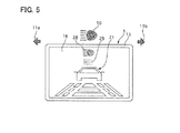
- FIG. 5 shows a front view of a main part of a combination meter 1 that displays a high-beam indication lamp 10 and display image 16 of a display 5.
- the parts similar to those of the first embodiment are described by using the same terms and the same reference numbers.
- the high-beam indication lamp 10 is arranged near an upper portion of the display 5 in the fourth embodiment.
- the fourth embodiment has an object to improve the degree of driver's recognition to lighting (a change in a lighting state) of the high-beam indication lamp 10.
- High-beam display images 28, 29 are displayed in the display image 16 displayed on the display 5 in synchronization with the lighting of the high-beam indication lamp 10, where the images 28, 29 have the shape similar to that of the high-beam indication lamp 10.
- the high-beam display images 28, 29 are arranged above the picture image 21 and near the high-beam indication lamp 10, and they are arranged on a straight line.
- the high-beam display image 28 is arranged above the high-beam display image 29, being larger than the high-beam display image 29 and smaller than the high-beam indication lamp 10.
- the colors of the high-beam display images 28, 29 are the same as that color (for example blue) of the high-beam indication display light 10.
- the brightness becomes lower in following orders of the high-beam indication lamp 10, the high-beam display image 28, and the high-beam display image 29.
- the tone may be changed in the same system color. In this case, the tone is set lighter in the following orders of the high-beam indication lamp 10, the high-beam display image 28, and the high-beam display image 29.
- the high-beam display images 28, 29 are displayed in the display image 16 displayed on the display 5 when the high-beam indication lamp 10 is turned on. This enables the driver who gazes the display image 16 on the display 5 to easily direct his or her mind toward the lighting of the high-beam indication lamp 10. Therefore, it can improve the degree of driver's recognition to the lighting of the high-beam indication lamp 10, preventing the driver from forgetting to turn off the high-beam and also from keeping running with the high-beam lamp ON.
- the high-beam display images 28, 29 have the designs similar to that of the high-beam indication lamp 10, so that the driver can easily image, based on the display of the high-beam display images 28, 29, that the high-beam indication lamp 10 is turned on. This improves the degree of driver's recognition to the lighting of the high-beam indication lamp 10.
- the high-beam display images 28, 29 are arranged near the high-beam indication lamp 10 and on the straight line. Therefore, this can provide a feeling of unity of the high-beam indication lamp 10 and the high-beam display images 28, 29.
- the display 5 is arranged at the position deeper than the instrument panel 2, which might degenerate a design of appearance, a feeling of unity, and a feeling of continuous display of the instrument panel 2 and the display 5.
- the high-beam display images 28, 29 are arranged near the high-beam indication lamp 10 and on the straight line, which can provide the feeling of unity and the feeling of continuous display of the display surface 5 a and the character panel surface 2a.
- the high-beam display images 28, 29 have the shapes similar to that of the high-beam indication lamp 10, the size of the high-beam display image 29 is set to be the smallest, the size of the high-beam display image 28 is set to be intermediate, and the size of the high-beam indication lamp 10 is set to be the largest. This can provide a stereoscopic dramatic impact having a sense of depth.
- the instrument device of the fourth embodiment has the following effect in addition to the effects (1) to (6).
- the indication lamp employs the high-beam indication lamp 10 that is arranged at the upper side of the display 5, so that the driver can easily recognize the shifting of the high-beam, thereby preventing the driver from keep running in a state where the high-beam lamps is kept turned on.
- the blinking timing of the arrow images 17, 18, 19, 20 may correspond to the blinking timing of the left-turn and right-turn signal indication lamps 11a, 11b.
- the blinking timing of the wave pattern images 24, 25 may correspond to the blinking timing of the left-turn and right-turn signal indication lamps (the left and right arrows 22a, 22b and the left and right wave pattern shapes 23a, 23b).
- left and right arrows 22a, 22b and the left and right wave pattern shapes 23a, 23b may have different light sources, respectively.
- the left and right wave pattern shapes 23a, 23b may be turned on later than those of the left and right arrows 22a, 22b.
- the colors of the gradation display parts 26, 27 are not limited to the color of the background, and they may be set appropriately.
- the high-beam display images 28, 29 may be blinked at different timing in order. That is, the display of the design displayed in the display image on the display may be varied in the same period as the change in the lighting state (lighting, blinking, a change in brightness) of the indication lamp.
Landscapes
- Engineering & Computer Science (AREA)
- Mechanical Engineering (AREA)
- Chemical & Material Sciences (AREA)
- Combustion & Propulsion (AREA)
- Transportation (AREA)
- Instrument Panels (AREA)
Abstract
Description
- The present invention relates to an instrument device.
- The patent document 1 discloses an instrument device that is arranged between a speed meter indicating a vehicle speed by an indicator needle and a tachometer indicating an engine speed by an indicator needle and on an instrument panel.
- Patent Document 1: Japanese Patent Application Laid-Open No.
2009-113700 - The above-described prior art, however, has a problem in that a degree of driver's recognition of a change in a lighting state (blinking etc.) of an indication lamp (a turn-signal indication lamp, a high beam lamp for example) becomes low compared to that of information on a display because the driver has a tendency to give his or her consciousness on an image on a display compared to an indication lamp (a turn-signal indication lamp, a high beam lamp for example) arranged on the instrument panel.
- The object of the present invention is to provide an instrument device that can improve a degree of driver's recognition to a change in a lighting state of an indication lamp.
- In order to solve the above-described problem, in the present invention, a design indicating an indication lamp changing a lighting state is displayed in a display image of a display.
- Therefore, the driver can be easily aware of the change in the lighting state of the indication lamp due to the design displayed in the display image on the display in a case where the driver's consciousness is directed to the display.
-
FIG. 1 is a front view showing a combination meter 1 of a first embodiment; -
FIG. 2 is a cross sectional view showing the combination meter 1 of the first embodiment; -
FIG. 3 is a front view showing a main part of a combination meter of a second embodiment which indicates left and right turn-signal indication lamps (left and right arrows, and left and right wave pattern shapes) and an image of a display; -
FIG. 4 is a front view showing a main part showing a combination meter of a third embodiment which indicates the left and right turn-signal indication lamps and an image of a display; and -
FIG. 5 is a front view showing a main part showing a combination meter of a forth embodiment which indicates a high beam indication lamp and an image of a display. - Hereinafter, embodiments to realize an instrument device of the present invention will be described with reference to the accompanying drawings.
- First, a construction of an instrument device of a first embodiment will be described.
-
FIG. 1 is a front view showing a combination meter (corresponding to an instrument device of the present invention) 1 of the first embodiment, and -
FIG. 2 is a cross sectional view showing the combination meter 1 of the first embodiment. - The combination meter 1 of the first embodiment is attached to be directed toward a rear side of a not-shown motor vehicle in a meter cluster provided on an instrument panel of the motor vehicle. In the combination meters 1, a
speed meter 3 and atachometer 4 are respectively arranged at the left side and the right side of a instrument panel 2, and adisplay 5 is arranged between thespeed meter 3 and thetachometer 4 to display picture images and others. Afuel gauge 6 is arranged at the left side of thespeed meter 3, and awater temperature gauge 7 is arranged at the right side of thetachometer 4. - Incidentally, the
speed meter 3 and thetachometer 4, and thefuel gauge 6 and thewater temperature gauge 7 are respectively arranged at a bilaterally symmetric position of thedisplay 5, employing analog indicators that indicates by using an indicating needle. Thedisplay 5 is built in the combination meters 1, which improves safeness because time for a driver to avert his or her gaze from the front sight of the motor vehicle can be almost the same as that for the driver to read the meters. - In the instrument panel 2, various warning lamps and indication lamps are arranged under each
meter display 5.
Specifically, they are a half-shutdoor warning lamp 8a, a seatbelt warning lamp 8b, an SRS airbag warning lamp 8c, anABS warning lamp 8d, abrake warning lamp 8e, aSLIP warning lamp 8f, an oilpressure warning lamp 8g, anengine warning lamp 8h, acharge warning lamp 8i, a VDCOFFindication lamp 8j, an A/T electronic controlsystem warning lamp 8k, an A/T selectposition indication lamp 8m, and a manualmode indication lamp 8n. Incidentally, 9a indicates a reset knob of a trip meter, and 9b indicates a push knob. A highbeam indication lamp 10 is arranged at the left side of thespeed meter 3 and above thefuel gauge 6. - In the instrument panel 2, left and right turn-signal indication lamps (corresponding to an indication lamp of the present invention) 11a, 11b are arranged close to the
display 5 and at the bilaterally symmetric position of thedisplay 5. The left turn-signal indication lamp 11a is shown as an arrow heading toward the left side, and the right turn-signal indication lamp 11b is shown as an arrow heading toward the right side. Each of them respectively notifies its operation by blinking the light. - On a display screen of the
display 5, information obtained by a not-shown car navigation system and information on the motor vehicle are displayed, while information on a fuel consumption, a power, a maintenance state and others may be also displayed. Further, a video picture obtained by a camera may be displayed in a case where the motor vehicle is a big size car or a van type car which are equipped with the camera monitoring both sides and the rear side of the motor vehicle. - As shown in
FIG. 2 , thedisplay 5 is fixed on acontrol circuit board 13 arranged at a rear side (a front side of the motor vehicle) of the instrument panel 2, and it'sdisplay surface 5a is arranged to be headed toward a front surface side (the rear side of the motor vehicle) of the instrument panel 2 through anopening 14 formed in the instrument panel 2.
In other words, a step is formed between thedisplay surface 5a of thedisplay 5 and acharacter panel surface 2a of the instrument panel 2, so that a driver sees thedisplay 5 at the position deeper than (at the front side of the motor vehicle) the instrument panel 2.
Incidentally, theopening 14 is closed by afinisher 15, which prevents the driver from seeing thecontrol circuit board 13.
On thecontrol circuit board 13, stepping motors each driving the indicating needle and LEDs used for each indication and warning lamp, including astepping motor 3b driving the indicatingneedle 3a of thespeed meter 3 and astepping motor 4b driving the indicatingneedle 4a of thetachometer 4, are arranged. - The displays of each
meter warning lamp 8a to 8n, 10, 11a, 11b, and display 5 in the combination meters 1 are controlled by a control unit (corresponding to a display control means of the present invention). Thecontrol unit 12 mainly consists of a well-known microcomputer having a CPU, a ROM, a RAM, as SRAM, an I/O which are provided on thecontrol circuit board 13, and bus lines, carrying out various process based on programs stored in the ROM and the RAM.
Thecontrol unit 12 receives the various information on the motor vehicle through a CAN and the information from the navigation system, and it controls to drive the stepping motors moving the indicating needles of themeters warning lamp 8a to 8n, 10, 11a, 11b and display contents of thedisplay 5. - Operations of the left and right turn-
signal indication lamps beam indication lamp 10 will be described as one example of the display contents.
The light of the left turn-signal indication lamp 11a is blinked when a left turn-signal indication switch is turned ON, while the light of the left turn-signal indication lamp 11a goes out when the left turn-signal indication switch is turned OFF. The light of the right turn-signal indication lamp 11b is blinked when a right turn-signal indication switch is turned ON, while the light of the right turn-signal indication lamp 11b goes out when the right turn-signal indication switch is turned OFF.
Incidentally, when the both of the left and right turn-signal switches are turned ON by ON of a hazard switch, the left and right turn-signal indication lamps
When head lamps are moved in an upward direction (a high beam state), the highbeam indication lamp 10 is lighted, while the highbeam indication lamp 10 is turned off when the head lamps are moved in a downward direction (a low beam state) or they are turned off. - In the first embodiment, in order to improve the degree of driver's recognition to the blinking (a change in a lighting state) of the left and right turn-
signal lamps arrow images signal lamps signal lamps display image 16 shown on thedisplay 5.
InFIG. 1 , adisplay image 21 indicating a predetermined state of the vehicle at the center of thedisplay image 16, thearrow images signal lamps display image 21.
Specifically, thearrow images display image 16 near the left turn-signal lamp 11a, and thearrow images display image 16 near the right turn-signal lamp 11b.
Thearrow images signal lamps
In other words, thearrow mages signal lamps - The
arrow images signal lamp 11a, and in the same direction as that of the left turn-signal lamp 11a. The sizes of the left turn-signal lamp 11a, thearrow image 17, and thearrow image 18 become smaller in these orders.
In addition, thearrow images signal lamp 11a, and the brightness of the left turn-signal lamp 11a, thearrow image 17 and thearrow image 18 become lower in these orders.
Incidentally, they may have the same system color and different tones instead of using the same color with different brightness. In this case, the tones of the left turn-signal lamp 11a, thearrow image 17 and thearrow image 18 become lower in these orders. Herein, the colors of the left turn-signal lamp 11a, thearrow image 17 and thearrow image 18 may have gradation.
A relationship between thearrow images signal indication lamp 11b is the same as that in which thearrow images signal indication lamp 11a are respectively replaced by thearrow images signal indication lamp 11b in the above-described explanation, and accordingly their explanations are omitted. - Herein, although the
arrow images FIG. 1 , in actual, thearrow images signal indication lamp 11a, at different timing and in these orders, while thearrow images signal indication lamp 11b, at different timing and in these orders. In other words, when the left turn-sigrtal indication lamp 11a is blinked, thearrow image 18, thearrow image 17, and the left-turn indication lamp 11a are blinked or displayed in a predetermined period in these orders.
When the right turn-signal indication lamp 11b is blinked, thearrow image 20, thearrow image 19, and the left-turn indication lamp 11b are blinked or displayed in the predetermined period in these orders.
Accordingly, thearrow images arrow images arrow images turn indication lamp - Next, the operation of the instrument device of the first embodiment will be displayed.
In the first embodiment, thedisplay 5 is arranged at the center of the instrument panel 2 in the left and right direction to display diverse information on the vehicle such as the information obtained from a car navigation system.
Herein, the information displayed in theimages 16 on thedisplay 5 can be displayed with many colors, decorations and others compared to the meters and the various displays/warning lamps arranged on the instrument panel 2. Accordingly, the consciousness of the driver has the tendency to be directed to the information in thedisplay images 16 when thedisplay image 16 is displayed on thedisplay 5.
This might cause a problem in that the driver drives the vehicle, turning on the left-turn or right-turn signal switch without regard to the blinking of the left-turn or right-turn signal indication lamp after the driver turns on the hazard switch, thereby turning on the left-turn and right-turn signal indication lamps. - On the contrary, in the combination meter 1 of the first embodiment, the
arrow images display image 16 displayed on thedisplay 5, so that the consciousness of the drive who gazes thedisplay image 16 on thedisplay 5 can be easily directed to the blinking of the left-turn or right-turnsignal indication lamp
This enables the degree of recognition of the driver to the blinking of left-turn or right-turnsignal indication lamp - Especially, the
arrow image signal indication lamps signal indication lamps arrow images arrow images signal indication lamps
Therefore, the degree of recognition of the driver to the blinking of the left-turn and right-turnsignal indication lamps - In addition, the
arrow images signal indication lamp 11a and also have the same direction, while thearrow images signal indication lamp 11b and also have the same direction. Therefore, the driver can easily image the blinking of the turn signal lamp when the driver sees the blinking displays of thearrow images signal indication lamp - In addition, in the first embodiment, the
arrow images signal indication lamp signal indication lamp arrow images
Herein, thedisplay 5 is arranged at the position deeper than the instrument panel 2, which might degenerate its design of appearance because the feeling of unity and continuous display of the instrument panel 2 and thedisplay 6 are degenerated due to the step formed by thedisplay surface 5a of thedisplay 5 and thecharacter panel surface 2a of the instrument panel 2.
On the contrary, thearrow images signal indication lamps display surface 5a and thecharacter panel surface 2a, improving the design of appearance of the combination meter 1. - In addition, in the first embodiment, using an arrangement where the
display surface 5 of thedisplay 5 is arranged at a vehicle front side far from the eye point (the position of eyes) of the driver, for example, when the left-turn signal switch is turned on, thearrow image 18, thearrow image 17, and the left-turnsignal indication lamp 11a is turned on or displayed in these orders.
Similarly, when the right-turn signal switch is turned on, thearrow image 20, thearrow image 19, and the right-turnsignal indication lamp 11b is turned on or displayed in these orders.
As a result, providing the feeling of the continuous display as if thedisplay surface 5a and thecharacter panel surface 2a are on the same display surface as described above, the first embodiment can provide a stereoscopic dramatic impact having a sense of depth as if the blinking of the left-turn and right-turnsignal indication lamps display surface 5a toward thecharacter panel surface 2a.
Further, in the first embodiment, thearrow images arrow images signal indication lamps - The instrument of the first embodiment can provide the effects listed below.
(1) The combination meter 1 equipped with thedisplay 5 in the instrument panel 2 has the left-turn and right-turnsignal indication lamps control unit 12 to display thearrow images signal indication lamps display image 16 on thedisplay 5. Therefore, thearrow images signal indication lamps - (2) The
control unit 12 controls to display thearrow images signal indication lamps arrow images signal indication lamps 11 a, 116. - (3) The
control unit 12 controls to display the arrow images thearrow images signal indication lamps arrow images - (4) The indication lams are arranged near the outer circumference of the
display 5, and thecontrol unit 15 controls to display thearrow images display image 16. Therefore, it can provide the feeling of unity or the left-turn and right-turnsignal indication lamps arrow images - (5) The
control unit 12 controls to display thearrow images - (6) The
display surface 5a of thedisplay 5 is arranged at the vehicle front side relative to thecharacter panel surface 2a of the instrument panel 2 to form the step between thedisplay surface 5a and thecharacter panel surface 2a. Therefore, it can provide the stereoscopic dramatic impact having the sense of depth. - (7) The indication lamps employ the left-turn and right-turn
signal indication lamps display 5. Therefore, it can prevent the driver from forgetting to turn off the hazard switch. -
FIG. 3 shows a front view of a main part of a combination meter 1 that displays left-turn and right-turn signal indication lamps (left andright arrows display image 16 on adisplay 5 according to a second embodiment of the present invention. Incidentally, the parts similar to those of the first embodiment are described by using the same terms, being indicated by the same reference numbers. - In the second embodiment, a
left arrow 22a and a leftwave pattern shape 23a are provided as a left-turn signal indication lamp, while aright arrow 22b and a rightwave pattern shape 23b are provided as a right-turn signal indication lamp.
The left andright arrows signal indication lamps wave pattern shape 23a is arranged between theleft arrow 22a and thedisplay 5, while the rightwave pattern shape 23b is arranged between theright arrow 22b and thedisplay 5. The left and right wave pattern shapes 23a, 23b have three different sized U-letter shapes that are built up to open toward the outer sides in a lateral direction of a motor vehicle to express spreading of the wave patterns. The left andright arrows wave pattern shape 23a is blinked at the same timing as that theleft arrow 22a by using the same light source (LED) as that of theleft arrow 22a. This operation is similar to that of the rightwave pattern shape 23b and theright arrow 22b. - In the second embodiment, the left and right
wave pattern images 24, 25 are displayed to be blinked in thedisplay image 16 displayed on thedisplay 5 in the same period as that of the blinking of the left-turn and right-turn signal indication lamp (the left andright arrows wave pattern images 24, 25 have the shapes similar to those of the left and right wave pattern shapes 23a, 23b.
The left and rightwave pattern images 24, 25 have three different U-letter shapes (firstU-letter shape parts U-letter shape parts U-letter shape parts - The left and right
wave pattern images 24, 25 are respectively displayed in these orders from the outer side in the lateral direction after the lighting in the blinking of the left-turn and right-turn signal indication lamps (the left andright arrows left arrow 22a and the left wave pattern shape 23 a) is turned on, the firstU-letter shape part 24a is turned on, the secondU-letter shape part 24b is turned on a little later than the lighting of the firstU-letter shape part 24a, and then the thirdU-letter shape part 24c is turned on a little later than the lighting of the secondU-letter shape part 24b.
Accordingly, the firstU-letter shape part 24a is surely turned on when the secondU-letter shape part 24b is turned on, and the first and secondU-letter shape parts U-letter shape part 24c is turned on.
When the left-turn signal indication lamp (theleft arrow 22a and the leftwave pattern shape 23a) is turned off, any ofU-letter shape part
The operation of the right wave pattern image 25 is similar to that of the leftwave pattern image 24. - Next, the operation of the instrument device of the second embodiment will be described.
In the second embodiment, when the left-turn signal switch is turned on for example, the left-turn signal indication lamp (theleft arrow 22a and the leftwave pattern shape 23a) is blinked in the period where the left-turn signal indication lamp blinks. Then the firstU-letter shape part 24a, the secondU-letter shape part 24b, and the thirdU-letter shape part 24c of the leftwave pattern image 24 are displayed in these orders.
Similarly, when the right-turn signal switch is turned on, in the period where the right-turn signal indication lamp (theright arrow 22b and the rightwave pattern shape 23b) is blinked, the right-turn signal indication lamp is blinked. Then the firstU-letter shape part 25a, the secondU-letter shape part 25b, and the thirdU-letter shape part 25c of the right wave pattern image 25 are displayed in these orders. - This can provide the effects similar to those of the first embodiment: a dramatic impact such that the wave pattern spreads in the
display image 16 on thedisplay 5 according to the lighting of the left-turn and right-turn signal indication lamps. The degree of driver's recognition to the blinking of the left-turn and right-turn signal indication lamps can be improved, a feeling of continuous display and unity of thedisplay surface 5a and thecharacter panel 2a, and a stereoscopic dramatic impact having a sense of depth such that the wave pattern spreads from thecharacter panel surface 2a toward thedisplay surface 5a. -
FIG. 4 shows a front view of a main part of a combination meter 1 that displays left-turn and right-turnsignal indication lamps display image 16 on adisplay 5 according to a third embodiment of the present invention. Incidentally, the parts similar to those of the first embodiment are described by using the same terms and the same reference numbers. - In the third embodiment,
gradation display parts display 5, where they gradate the colors of background of adisplay image 16 displayed on adisplay 5 in the same period as that of blinking of the left-turn and right-turnsignal indication lamps
The leftgradation display part 26 corresponds to the blinking of the left-turnsignal indication lamp 11a, while the rightgradation display part 27 corresponds to the blinking of the right-turnsignal indication lamp 11b. Thegradation display parts display image 16 gradually becomes lighter from the left and right upper corners of thedisplay 5, which expresses spreading of wave pattern on thedisplay image 16 similarly to the left and rightwave pattern images 24, 25 of the second embodiment. The outer edges of thegradation display parts picture image 21 displayed in thedisplay image 16. - Next, the operation of the instrument device of the third embodiment will be described.
- In the third embodiment, the color of the background of the
display image 16 displayed on thedisplay 5 is gradated in the same period as that of the blinking of the left-turn and right-turnsignal indication lamps display image 16 on thedisplay 5 according to the lighting of the left-turn and right-turn signal indication lamps. The degree of driver's recognition to the blinking of the left-turn and right-turn signal indication lamps can be improved, a feeling of continuous display and unity of thedisplay surface 5a and thecharacter panel 2a, and a stereoscopic dramatic impact having a sense of depth such that the wave pattern spreads from thecharacter panel surface 2a toward thedisplay surface 5a. -
FIG. 5 shows a front view of a main part of a combination meter 1 that displays a high-beam indication lamp 10 anddisplay image 16 of adisplay 5. Incidentally, the parts similar to those of the first embodiment are described by using the same terms and the same reference numbers. - As shown in
FIG. 5 , the high-beam indication lamp 10 is arranged near an upper portion of thedisplay 5 in the fourth embodiment. - The fourth embodiment has an object to improve the degree of driver's recognition to lighting (a change in a lighting state) of the high-
beam indication lamp 10. High-beam display images display image 16 displayed on thedisplay 5 in synchronization with the lighting of the high-beam indication lamp 10, where theimages beam indication lamp 10. The high-beam display images picture image 21 and near the high-beam indication lamp 10, and they are arranged on a straight line.
The high-beam display image 28 is arranged above the high-beam display image 29, being larger than the high-beam display image 29 and smaller than the high-beam indication lamp 10.
The colors of the high-beam display images indication display light 10. The brightness becomes lower in following orders of the high-beam indication lamp 10, the high-beam display image 28, and the high-beam display image 29.
Incidentally, instead of the different brightness in the same color, the tone may be changed in the same system color. In this case, the tone is set lighter in the following orders of the high-beam indication lamp 10, the high-beam display image 28, and the high-beam display image 29. - Next, the operation of the instrument device of the fourth embodiment will be described.
- In the combination meter 1 of the fourth embodiment, the high-
beam display images display image 16 displayed on thedisplay 5 when the high-beam indication lamp 10 is turned on. This enables the driver who gazes thedisplay image 16 on thedisplay 5 to easily direct his or her mind toward the lighting of the high-beam indication lamp 10. Therefore, it can improve the degree of driver's recognition to the lighting of the high-beam indication lamp 10, preventing the driver from forgetting to turn off the high-beam and also from keeping running with the high-beam lamp ON.
Especially, the high-beam display images beam indication lamp 10, so that the driver can easily image, based on the display of the high-beam display images beam indication lamp 10 is turned on. This improves the degree of driver's recognition to the lighting of the high-beam indication lamp 10. - In addition, in the fourth embodiment, the high-
beam display images beam indication lamp 10 and on the straight line. Therefore, this can provide a feeling of unity of the high-beam indication lamp 10 and the high-beam display images display 5 is arranged at the position deeper than the instrument panel 2, which might degenerate a design of appearance, a feeling of unity, and a feeling of continuous display of the instrument panel 2 and thedisplay 5.
On the contrary, the high-beam display images beam indication lamp 10 and on the straight line, which can provide the feeling of unity and the feeling of continuous display of thedisplay surface 5 a and thecharacter panel surface 2a.
Further, in the fourth embodiment, the high-beam display images beam indication lamp 10, the size of the high-beam display image 29 is set to be the smallest, the size of the high-beam display image 28 is set to be intermediate, and the size of the high-beam indication lamp 10 is set to be the largest. This can provide a stereoscopic dramatic impact having a sense of depth. - As described above, the instrument device of the fourth embodiment has the following effect in addition to the effects (1) to (6).
(8) The indication lamp employs the high-beam indication lamp 10 that is arranged at the upper side of thedisplay 5, so that the driver can easily recognize the shifting of the high-beam, thereby preventing the driver from keep running in a state where the high-beam lamps is kept turned on. - While the instrument device of the present invention has been described based on the embodiments, its concrete construction is not limited to the embodiments. A design change and an addition are covered by the present invention as long as it does not depart from the scope of the invention.
For example, in the first embodiment, the blinking timing of thearrow images signal indication lamps
In the second embodiment, the blinking timing of thewave pattern images 24, 25 may correspond to the blinking timing of the left-turn and right-turn signal indication lamps (the left andright arrows right arrows right arrows - In addition, in the third embodiment, the colors of the
gradation display parts
Further, in the fourth embodiment, when the high-beam indication lamp 10 is turned on, the high-beam display images -
- 1
- combination meters (instrument device)
- 2
- instrument panel
- 2a
- character panel surface
- 5
- display
- 5a
- display surface
- 10
- high beam indication lamp (indication lamp)
- 11a
- left turn-signal indication lamp (indication lamp)
- 11b
- right turn-signal indication lamp (indication lamp)
- 12
- control unit (display control means)
- 16
- display image
- 17, 18, 19, 20
- arrow image (design)
- 22a
- left directional arrow (indication lamp)
- 22b
- right directional arrow (indication lamp)
- 23a
- left wave pattern shape (indication lamp)
- 23b
- right wave pattern shape (indication lamp)
- 24
- left wave pattern image (design)
- 25
- right wave pattern image (design)
- 26
- left gradation display part (design)
- 27
- right gradation display part (design)
- 28
- high beam display image (design)
- 29
- high beam display image (design)
Claims (8)
- An instrument device equipped with a display in an instrument panel, comprising:an indication lamp arranged on the instrument panel, anda display control means for displaying a design indicating a change in a lighting state of the indication lamp in an screen image on the display.
- The instrument device according to claim 1, wherein
the display control means changes a display mode of a design in the same period as a period of a change in lighting state of the indication lamp. - The instrument device according to claim 1 or 2, wherein
the display control means controls to display a design having a shape similar to a shape of the indication lamp. - The instrument device according to any one of claims 1 to 3, wherein the indication lamp is arranged in vicinity of a circumference of the display, and wherein
the control means controls to display the design at a position closer to the indication lamp than a position compared to a center position of the display image. - The instrument device according to claim 4, wherein
the display control means controls to display a plurality of the designs arranged on one of a straight line and a curved line together with the indication lamp. - The instrument device according to any one of claims 1 to 5, wherein
a step is provided between a screen surface of the display and a character panel surface of the installment panel. - The instrument device according to any one of claims 1 to 6, wherein
the indication lamp comprises turn-signal indication lamps respectively arranged at a left side and a right side of the display. - The instrument device according to any one of claims 1 to 6, wherein the indication lamp comprises a high beam indication lamp arranged at one of above the display, under the display and in a front and back direction of a motor vehicle.
Applications Claiming Priority (2)
| Application Number | Priority Date | Filing Date | Title |
|---|---|---|---|
| JP2010110182A JP5362646B2 (en) | 2010-05-12 | 2010-05-12 | Meter device |
| PCT/JP2011/059490 WO2011142212A1 (en) | 2010-05-12 | 2011-04-18 | Meter device |
Publications (2)
| Publication Number | Publication Date |
|---|---|
| EP2570286A1 true EP2570286A1 (en) | 2013-03-20 |
| EP2570286A4 EP2570286A4 (en) | 2015-04-22 |
Family
ID=44914268
Family Applications (1)
| Application Number | Title | Priority Date | Filing Date |
|---|---|---|---|
| EP11780469.0A Withdrawn EP2570286A4 (en) | 2010-05-12 | 2011-04-18 | MEASURING DEVICE |
Country Status (4)
| Country | Link |
|---|---|
| US (1) | US20130076503A1 (en) |
| EP (1) | EP2570286A4 (en) |
| JP (1) | JP5362646B2 (en) |
| WO (1) | WO2011142212A1 (en) |
Cited By (1)
| Publication number | Priority date | Publication date | Assignee | Title |
|---|---|---|---|---|
| CN104015622A (en) * | 2014-06-26 | 2014-09-03 | 隆鑫通用动力股份有限公司 | Digital instrument with flash relay function for motorcycle |
Families Citing this family (11)
| Publication number | Priority date | Publication date | Assignee | Title |
|---|---|---|---|---|
| US8878660B2 (en) * | 2011-06-28 | 2014-11-04 | Nissan North America, Inc. | Vehicle meter cluster |
| JP5949052B2 (en) * | 2012-03-29 | 2016-07-06 | 日産自動車株式会社 | Vehicle display device |
| CN102837613B (en) * | 2012-08-21 | 2015-06-17 | 广东好帮手电子科技股份有限公司 | Auto meter and indicator light information informing method thereof |
| US8841995B2 (en) * | 2012-09-14 | 2014-09-23 | Nissan North America, Inc. | Stealth mode for indicia used to display vehicle operation |
| JP6498995B2 (en) * | 2014-05-19 | 2019-04-10 | 矢崎総業株式会社 | Vehicle display device |
| JP6387556B2 (en) * | 2014-10-24 | 2018-09-12 | ヤンマー株式会社 | Tractor |
| WO2016063953A1 (en) * | 2014-10-24 | 2016-04-28 | ヤンマー株式会社 | Work vehicle |
| US10688920B1 (en) * | 2019-01-25 | 2020-06-23 | Toyota Motor Engineering & Manufacturing North America, Inc. | System and method for configuring vehicle components according to rules associated with a vehicle location |
| JP7405064B2 (en) * | 2020-12-07 | 2023-12-26 | 株式会社デンソー | display device |
| DE102021202246B4 (en) | 2021-03-09 | 2024-08-08 | Volkswagen Aktiengesellschaft | Improved visualization with an AR HUD |
| JP2024119300A (en) * | 2023-02-22 | 2024-09-03 | 豊田合成株式会社 | Vehicle interior panels |
Family Cites Families (14)
| Publication number | Priority date | Publication date | Assignee | Title |
|---|---|---|---|---|
| JPH069947B2 (en) * | 1990-02-22 | 1994-02-09 | 株式会社イシカワ製作所 | Vehicle direction indicator |
| DE19740575A1 (en) * | 1997-09-15 | 1999-03-18 | Bosch Gmbh Robert | Display device, especially for instrument combination of motor vehicle |
| JP2004114816A (en) * | 2002-09-26 | 2004-04-15 | Kanto Auto Works Ltd | Instrument panel of automobile |
| US20050187710A1 (en) * | 2004-02-20 | 2005-08-25 | Walker James A. | Vehicle navigation system turn indicator |
| JP2005349989A (en) * | 2004-06-11 | 2005-12-22 | Herutsu Project Kk | Auxiliary turn signal lamp |
| JP4118923B2 (en) * | 2004-12-14 | 2008-07-16 | 富士通テン株式会社 | Display device and in-vehicle display device |
| US20070233361A1 (en) * | 2006-03-30 | 2007-10-04 | Ford Global Technologies, Llc | Centralized Image Processing For An Automobile With A Navigation System |
| US7443284B2 (en) * | 2006-05-09 | 2008-10-28 | International Business Machines Corporation | Method and system for sending events between vehicles |
| JP2008032603A (en) * | 2006-07-31 | 2008-02-14 | Clarion Co Ltd | Navigation apparatus, method, and program |
| JP2009113700A (en) | 2007-11-08 | 2009-05-28 | Nippon Seiki Co Ltd | Display device for vehicle |
| JP5000590B2 (en) * | 2008-06-25 | 2012-08-15 | 株式会社デンソーアイティーラボラトリ | Peripheral information display device and peripheral information display method |
| US7554436B2 (en) * | 2008-10-16 | 2009-06-30 | Keller Lucius W | Self-contained turn signal indicator unit |
| JP4868055B2 (en) * | 2009-11-04 | 2012-02-01 | 株式会社デンソー | Display device |
| US20110187518A1 (en) * | 2010-02-02 | 2011-08-04 | Ford Global Technologies, Llc | Steering wheel human/machine interface system and method |
-
2010
- 2010-05-12 JP JP2010110182A patent/JP5362646B2/en not_active Expired - Fee Related
-
2011
- 2011-04-18 WO PCT/JP2011/059490 patent/WO2011142212A1/en not_active Ceased
- 2011-04-18 EP EP11780469.0A patent/EP2570286A4/en not_active Withdrawn
- 2011-04-18 US US13/696,834 patent/US20130076503A1/en not_active Abandoned
Cited By (1)
| Publication number | Priority date | Publication date | Assignee | Title |
|---|---|---|---|---|
| CN104015622A (en) * | 2014-06-26 | 2014-09-03 | 隆鑫通用动力股份有限公司 | Digital instrument with flash relay function for motorcycle |
Also Published As
| Publication number | Publication date |
|---|---|
| US20130076503A1 (en) | 2013-03-28 |
| JP5362646B2 (en) | 2013-12-11 |
| EP2570286A4 (en) | 2015-04-22 |
| WO2011142212A1 (en) | 2011-11-17 |
| JP2011235805A (en) | 2011-11-24 |
Similar Documents
| Publication | Publication Date | Title |
|---|---|---|
| US20130076503A1 (en) | Instrument device | |
| JP7408254B2 (en) | Vehicle display device | |
| KR101947927B1 (en) | Display apparatus | |
| JP6445414B2 (en) | Display device | |
| JP4254719B2 (en) | Vehicle display device | |
| JP2008209724A (en) | Headup display device for vehicle | |
| AU2015338479B2 (en) | Information providing apparatus | |
| JP2008189201A (en) | Visual assist device for vehicles | |
| US10224006B2 (en) | Display device for vehicle | |
| EP2933146B1 (en) | Vehicle interior illuminating device | |
| JP2016203903A (en) | Vehicle display device | |
| JP2019028102A (en) | Image display device and image display method | |
| EP2865556A1 (en) | Display device for vehicle | |
| KR20140052040A (en) | Display device for a vehicle | |
| US6951399B2 (en) | Meter unit | |
| JP4735845B2 (en) | Lighting control device for instrument panel for vehicle | |
| JP2012061874A (en) | Indication apparatus for vehicle | |
| JP5910848B2 (en) | Vehicle display device | |
| JP2004157084A (en) | Lighting method and lighting device for instrument panel for vehicle | |
| JP2010100261A (en) | Vehicle state display | |
| JP5557095B2 (en) | Vehicle instrument | |
| JP7803198B2 (en) | Display system and display control method | |
| JP2017140983A (en) | Display device for vehicle | |
| JP5062124B2 (en) | Vehicle display device | |
| JP2026021867A (en) | Vehicular display control device, vehicular display system, and vehicular display control method |
Legal Events
| Date | Code | Title | Description |
|---|---|---|---|
| PUAI | Public reference made under article 153(3) epc to a published international application that has entered the european phase |
Free format text: ORIGINAL CODE: 0009012 |
|
| 17P | Request for examination filed |
Effective date: 20121205 |
|
| AK | Designated contracting states |
Kind code of ref document: A1 Designated state(s): AL AT BE BG CH CY CZ DE DK EE ES FI FR GB GR HR HU IE IS IT LI LT LU LV MC MK MT NL NO PL PT RO RS SE SI SK SM TR |
|
| DAX | Request for extension of the european patent (deleted) | ||
| RA4 | Supplementary search report drawn up and despatched (corrected) |
Effective date: 20150323 |
|
| RIC1 | Information provided on ipc code assigned before grant |
Ipc: B60Q 1/00 20060101ALI20150317BHEP Ipc: B60K 37/02 20060101ALI20150317BHEP Ipc: B60K 35/00 20060101AFI20150317BHEP |
|
| STAA | Information on the status of an ep patent application or granted ep patent |
Free format text: STATUS: THE APPLICATION IS DEEMED TO BE WITHDRAWN |
|
| 18D | Application deemed to be withdrawn |
Effective date: 20151103 |