EP2570210A1 - Cutting insert for copy turning - Google Patents
Cutting insert for copy turning Download PDFInfo
- Publication number
- EP2570210A1 EP2570210A1 EP12184424A EP12184424A EP2570210A1 EP 2570210 A1 EP2570210 A1 EP 2570210A1 EP 12184424 A EP12184424 A EP 12184424A EP 12184424 A EP12184424 A EP 12184424A EP 2570210 A1 EP2570210 A1 EP 2570210A1
- Authority
- EP
- European Patent Office
- Prior art keywords
- cutting
- cutting edge
- cutting insert
- insert
- edge
- Prior art date
- Legal status (The legal status is an assumption and is not a legal conclusion. Google has not performed a legal analysis and makes no representation as to the accuracy of the status listed.)
- Withdrawn
Links
Images


Classifications
-
- B—PERFORMING OPERATIONS; TRANSPORTING
- B23—MACHINE TOOLS; METAL-WORKING NOT OTHERWISE PROVIDED FOR
- B23B—TURNING; BORING
- B23B27/00—Tools for turning or boring machines; Tools of a similar kind in general; Accessories therefor
- B23B27/14—Cutting tools of which the bits or tips or cutting inserts are of special material
- B23B27/141—Specially shaped plate-like cutting inserts, i.e. length greater or equal to width, width greater than or equal to thickness
- B23B27/145—Specially shaped plate-like cutting inserts, i.e. length greater or equal to width, width greater than or equal to thickness characterised by having a special shape
-
- B—PERFORMING OPERATIONS; TRANSPORTING
- B23—MACHINE TOOLS; METAL-WORKING NOT OTHERWISE PROVIDED FOR
- B23B—TURNING; BORING
- B23B2200/00—Details of cutting inserts
- B23B2200/04—Overall shape
- B23B2200/0423—Irregular
-
- B—PERFORMING OPERATIONS; TRANSPORTING
- B23—MACHINE TOOLS; METAL-WORKING NOT OTHERWISE PROVIDED FOR
- B23B—TURNING; BORING
- B23B2200/00—Details of cutting inserts
- B23B2200/28—Angles
-
- B—PERFORMING OPERATIONS; TRANSPORTING
- B23—MACHINE TOOLS; METAL-WORKING NOT OTHERWISE PROVIDED FOR
- B23B—TURNING; BORING
- B23B2205/00—Fixation of cutting inserts in holders
- B23B2205/02—Fixation using an elastically deformable clamping member
Definitions
- the invention relates to a cutting plate for copy turning.
- Cutting plates for copy turning are known per se. They are often formed as flat cutting plates with a central mounting hole. With their underside, these inserts are on a correspondingly shaped receiving surface of the tool holder and are fixed by the central fixing screw. This means that a special tool holder with a fastening thread and a receiving surface is required for this copying cutting plate.
- a cutting plate is known, which has proven very effective during grooving.
- the cutting plates are not fixed with a central fastening screw in the tool holder, but the inserts are in the tool holder between an upper side and a Bottom of the cutting plate clamped.
- the grooving insert is narrow and tall in cross section and not rather flat and wide, like conventional trays.
- the invention is based on the object to provide a cutting plate for copy turning, of course, has good cutting properties, is inexpensive to produce and is compatible with a cutting plate for piercing, so first, the production costs are minimized and, secondly, the same tool holder can be used.
- a cutting plate for copying with a base body, two side surfaces, a top, and a bottom, and two end faces, wherein a main cutting edge is formed by the cutting edge between the top and an end face, wherein the minor cutting edges at least approximately parallel to a longitudinal axis run the cutting plate and wherein the cutting plate is fixed by a clamping between the top and bottom of a tool holder, according to the invention solved in that at an angle ⁇ to a secondary cutting edge another cutting edge is provided, and that an intersection between secondary cutting edge and further cutting in the Cutting edge between the top and the face is.
- Part of the rationalization effects relates to the production of cutting inserts according to the invention. These can be through subsequent reworking, in particular by grinding with diamond grains as a cutting material produced. This meant that no new or modified mold was required for sintering the insert according to the invention.
- cutting inserts whose secondary cutting edge is deficient to convert to a flawless cutting insert according to the invention for copy turning.
- refurbishing a cutting insert for piercing in a cutting insert according to the invention for copy turning namely a minor cutting is completely removed by grinding, so that any defects in the area of this minor cutting edge for the finished insert for copy turning are of no importance. This can reduce the reject rate and increase output.
- angles between the remaining minor cutting edge and the further cutting edge have proven to be smaller than 60 ° and are preferably equal to 55, 35 ° or equal to 25 °. At this angle, it is recommended that an angle compatible with the relevant DIN or ISO standards is selected. This means that the recesses formed in the top of the blank have two functions, depending on whether the insert is used for piercing or copy-turning.
- the recesses guide and deform the resulting chip and provide good chip flow. This is especially important for difficult to machine and tough materials.
- the cutting insert according to the invention can be used for machining difficult-to-machine materials, stellites, inconel, various non-ferrous metals, light metals (eg aluminum and aluminum alloys), plastics, rubber and other exotic materials.
- the main cutting edge and / or the secondary cutting edge can be sharpened or slightly rounded.
- Another advantage of the insert according to the invention is the fact that at both ends of the insert a cutting edge according to the invention is designed for copy turning. This makes it possible to provide two cutters for copy turning on a cutting plate, so that after the wear of the first cutting edge by turning over the cutting insert another cutting edge is available.
- a clamping rib is formed on the upper side, which preferably has a circular-arc-shaped or sinusoidal cross-section.
- a V-shaped contour which cooperates in a correspondingly shaped trapezoidal or V-shaped groove in the tool holder.
- the clamping rib at the top and the V-shaped contour at the bottom allow safe, precise and extremely resilient clamping of the cutting plate, so that the lateral forces inevitably occurring during copy turning can be safely introduced from the cutting plate into the tool holder, without it Relative movements between insert and tool holder comes.
- the end faces have in the region of the bottom serving as a stop paragraph.
- the cutting edge used as a (depth) stop the insert in the tool holder but the claimed paragraph.
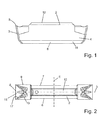
- the cutting plate 1 is shown in a side view.
- the cutting plate 1 is shown in a plan view of its upper side 2.
- the cutting plate 1 is formed as a turning cutting plate. That is, it is mirror-symmetrical to a center plane E. Furthermore, it is also mirror-symmetrical with respect to a longitudinal axis or a longitudinal plane L.
- the cutting insert 1 has a base body 4 which comprises the upper side 2, a lower side 5, two oppositely disposed and obliquely extending side surfaces 6 and 7, and two obliquely opposite end faces 3. Because of the symmetry to the center plane E is only one end face 3 in the Figures 1 and 2 shown.
- a cutting edge between the top 2 and the end face 3 forms a main cutting edge 8, followed by the side cutting 9 and 10 on both sides.
- the minor cutting edges 9 and 10 are each formed by the cutting line between a side surface 6 and 7 and the upper side 2.
- the secondary cutting edges 9 and 10 extend approximately parallel to the longitudinal plane L of the base body. They do not run exactly parallel to the longitudinal plane L, so that the spaced apart from the main cutting edge 3 areas of the minor cutting edges 9 and 10 are free during grooving.
- a rake face 15, has, as out FIG. 2 apparent, a complex geometry.
- the rake surface 15 is formed in the region immediately behind the cutting edge 8 as a concave depression. This results in an edge 17, which is the cutting edge between the concave depression in the rake face 15 and the remaining part of the rake face.
- this edge 17 to form a further cutting edge. This is achieved by removing a large part of the rake surface 15, the main cutting edge 8 and also the majority of the secondary cutting edge 9 by grinding.
- the secondary cutting edge 10 stops and along the edge 17 forms a further cutting edge 17 stand.
- FIG. 4 is a second optional way of reworking a cutting plate according to FIG. 2 to an insert according to the invention for copy turning shown.
- more material is ground, so that the further cutting edge 17 extends to the side 7 of the cutting plate.
- the processing is easier, but more material must be removed.
- FIG. 5 is a further embodiment of an insert according to the invention shown.
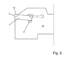
- FIG. 6 is an inventive insert 1 according to the in FIG. 3 illustrated embodiment, as it is clamped in a tool holder 21.
- the clamping takes place via the clamping rib 12 and the V-shaped bevels 11 on the cutting plate 1 and correspondingly shaped grooves in the tool holder 21st
- This type of tension is well known in the art, particularly the P92 range Utility model owner known and proven.
- One of the advantages of the cutting insert 1 according to the invention is that the cutting insert 1 according to the invention can use this tool holder 21, which is optimally introduced on the market, for copy turning.
- FIG. 7 is the inclusion and clamping of a cutting plate according to FIG. 5 shown in a tool holder 21.
- the tool holder 21 has a projection 23 which, together with the shoulder 19 on the underside 6 of the cutting plate forms a stop and thereby the positioning of the cutting plate 1 in the tool holder 21 even more precise than in the embodiment according to FIG FIG. 6 power.
- FIG. 7 illustrated variant with a shoulder 19 in the cutting plate and a projection 23 in the tool holder to prefer.
Landscapes
- Engineering & Computer Science (AREA)
- Mechanical Engineering (AREA)
- Cutting Tools, Boring Holders, And Turrets (AREA)
Abstract
Description
Die Erfindung betrifft eine Schneidplatte zum Kopierdrehen.The invention relates to a cutting plate for copy turning.
Schneidplatten zum Kopierdrehen sind an sich bekannt. Sie werden häufig als flache Schneidplatten mit einer zentralen Befestigungsbohrung ausgebildet. Mit ihrer Unterseite liegen diese Schneidplatten auf einer entsprechend gestalteten Aufnahmefläche des Werkzeughalters auf und werden durch die zentrale Befestigungsschraube fixiert. Dies bedeutet, dass zu dieser Kopierschneidplatte ein spezieller Werkzeughalter mit einem Befestigungsgewinde und einer Aufnahmefläche erforderlich ist.Cutting plates for copy turning are known per se. They are often formed as flat cutting plates with a central mounting hole. With their underside, these inserts are on a correspondingly shaped receiving surface of the tool holder and are fixed by the central fixing screw. This means that a special tool holder with a fastening thread and a receiving surface is required for this copying cutting plate.
Aus der
Der Erfindung liegt die Aufgabe zu Grunde, eine Schneidplatte zum Kopierdrehen bereit zu stellen, die natürlich gute Zerspanungseigenschaften hat, kostengünstig herstellbar ist und mit einer Schneidplatte zum Stechdrehen kompatibel ist, sodass erstens die Herstellungskosten minimiert werden und zweitens der gleiche Werkzeughalter eingesetzt werden kann.The invention is based on the object to provide a cutting plate for copy turning, of course, has good cutting properties, is inexpensive to produce and is compatible with a cutting plate for piercing, so first, the production costs are minimized and, secondly, the same tool holder can be used.
Diese Aufgabe wird bei einer Schneidplatte zum Kopierdrehen mit einem Grundkörper, zwei Seitenflächen, einer Oberseite, und einer Unterseite, und zwei Stirnflächen, wobei eine Hauptschneide durch die Schnittkante zwischen der Oberseite und einer Stirnfläche gebildet wird, wobei die Nebenschneiden zumindest nährungsweise parallel zu einer Längsachse der Schneidplatte verlaufen und wobei die Schneidplatte durch eine Klemmung zwischen Oberseite und Unterseite an einem Werkzeughalter fixierbar ist, erfindungsgemäß dadurch gelöst, dass in einem Winkel α zu einer Nebenschneide eine weitere Schneide vorgesehen ist, und dass ein Schnittpunkt zwischen Nebenschneide und weiterer Schneide im Bereich der Schnittkante zwischen der Oberseite und der Stirnfläche liegt.This object is achieved with a cutting plate for copying with a base body, two side surfaces, a top, and a bottom, and two end faces, wherein a main cutting edge is formed by the cutting edge between the top and an end face, wherein the minor cutting edges at least approximately parallel to a longitudinal axis run the cutting plate and wherein the cutting plate is fixed by a clamping between the top and bottom of a tool holder, according to the invention solved in that at an angle α to a secondary cutting edge another cutting edge is provided, and that an intersection between secondary cutting edge and further cutting in the Cutting edge between the top and the face is.
Erfindungsgemäß ist es somit möglich, durch Umschleifen einer herkömmlichen Schneidplatte zum Stechdrehen eine Schneidplatte zum Kopierdrehen herzustellen. Weil sich das Umschleifen oder Umarbeiten einer handelsüblichen Schneidplatte zum Stechdrehen sich lediglich auf den Bereich der Hauptschneide und einer Nebenschneide beschränkt, bleibt der zentrale Teil des Grundkörpers unverändert, sodass für beide Schneidplatten der gleiche Werkzeughalter eingesetzt werden kann. Dadurch ergeben sich erhebliche Rationalisierungseffekte.According to the invention, it is thus possible to produce a cutting plate for copy turning by regrinding a conventional insert for piercing. Because the regrinding or reworking of a commercial cutting plate for piercing is limited only to the area of the main cutting edge and a secondary cutting edge, the central part of the base body remains unchanged, so that the same tool holder can be used for both cutting plates. This results in considerable rationalization effects.
Ein Teil der Rationalisierungseffekte betrifft die Herstellung der erfindungsgemäßen Schneidplatten. Diese können durch nachträgliches Umarbeiten, insbesondere durch Schleifen mit Diamantkörnern als Schneidstoff, hergestellt werden. Dies bedeutete, dass keine neue oder geänderte Pressform zum Sintern der erfindungsgemäßen Schneidplatte erforderlich ist.Part of the rationalization effects relates to the production of cutting inserts according to the invention. These can be through subsequent reworking, in particular by grinding with diamond grains as a cutting material produced. This meant that no new or modified mold was required for sintering the insert according to the invention.
Des Weiteren ist es möglich, beispielsweise Schneidplatten, deren eine Nebenschneide mangelhaft ist, zu einer makellosen erfindungsgemäßen Schneidplatte zum Kopierdrehen umzuarbeiten. Beim Umarbeiten einer Schneidplatte zum Stechdrehen in eine erfindungsgemäße Schneidplatte zum Kopierdrehen wird nämlich eine Nebenschneide vollständig durch Schleifen abgetragen, sodass eventuelle Fehlstellen im Bereich dieser Nebenschneide für die fertige Schneidplatte zum Kopierdrehen ohne Bedeutung sind. Dadurch kann die Ausschussquote verringert und die Ausbringung erhöht werden.Furthermore, it is possible, for example, cutting inserts whose secondary cutting edge is deficient to convert to a flawless cutting insert according to the invention for copy turning. When refurbishing a cutting insert for piercing in a cutting insert according to the invention for copy turning namely a minor cutting is completely removed by grinding, so that any defects in the area of this minor cutting edge for the finished insert for copy turning are of no importance. This can reduce the reject rate and increase output.
Ein weiterer wesentlicher Vorteil ist auf der Anwenderseite zu sehen. Der Anwender kann nämlich mit einem und dem gleichen Werkzeughalter sowohl Stechdrehen als auch Kopierdrehen. Dies verringert die erforderliche Zahl von Werkzeughaltern und hilft dadurch auch im erheblichen Maße Kosten einzusparen.Another significant advantage can be seen on the user side. The user can namely with one and the same tool holder both lancing and copy turning. This reduces the required number of tool holders and thereby helps to save considerable costs.
Zum Kopierdrehen haben sich Winkel zwischen der stehengebliebenen Nebenschneide und der weiteren Schneide bewährt, die kleiner als 60° sind und bevorzugt gleich 55, 35° oder gleich 25° sind. Es empfiehlt sich bei diesem Winkel darauf zu achten, dass ein mit den einschlägigen DIN oder ISO Standards/Normen kompatibler Winkel gewählt wird. Dies bedeutet, dass die in der Oberseite der des Rohlings ausgeformten Vertiefungen zwei Funktionen haben, je nachdem ob die Schneidplatte zum Stechdrehen oder zum Kopierdrehen eingesetzt wird.For copy turning, angles between the remaining minor cutting edge and the further cutting edge have proven to be smaller than 60 ° and are preferably equal to 55, 35 ° or equal to 25 °. At this angle, it is recommended that an angle compatible with the relevant DIN or ISO standards is selected. This means that the recesses formed in the top of the blank have two functions, depending on whether the insert is used for piercing or copy-turning.
Wenn die Schneidplatte zum Stechdrehen eingesetzt wird, dann leiten und verformen die Vertiefungen den entstehenden Span und sorgen für einen guten Spanfluß. Dies ist besonders wichtig bei schwer zerspanbaren und zähen Werkstoffen.When the insert is used for piercing, the recesses guide and deform the resulting chip and provide good chip flow. This is especially important for difficult to machine and tough materials.
Die erfindungsgemäße schneidplatte kann zum Zerspanen von schwer zerspanbaren Werkstoffen, Stellite, Inconel, verschiedenen Buntmetallen, Leichtmetallen (z. B. Aluminium und Al-Legierungen), Kunststoffen, Gummi und anderen exotischen Materialien eingesetzt werden.The cutting insert according to the invention can be used for machining difficult-to-machine materials, stellites, inconel, various non-ferrous metals, light metals (eg aluminum and aluminum alloys), plastics, rubber and other exotic materials.
Wenn die Schneidplatte zum Kopierdrehen eingesetzt wird, dann entsteht durch das erfindungsgemäße Umschleifen aus einer solchen Vertiefung eine Nebenschneide.If the insert is used for copy turning, then by the inventive regrinding from such a recess a secondary cutting edge.
In vielen Anwendungsfällen hat es sich als vorteilhaft erwiesen, die Oberfläche der Schneidplatte zumindest bereichsweise zu polieren, so dass der Spanfluss verbessert und die Lebensdauer erhöht wird.In many applications, it has proven to be advantageous to at least partially polish the surface of the cutting insert so that the chip flow is improved and the service life is increased.
Je nach Anwendungsfall und zu bearbeitendem Werkstoff können die Hauptschneide und/oder die Nebenschneide scharf geschliffen oder auch leicht verrundet werden.Depending on the application and the material to be machined, the main cutting edge and / or the secondary cutting edge can be sharpened or slightly rounded.
Ein weiterer Vorteil der erfindungsgemäßen Schneidplatte ist darin zu sehen, dass an beiden Enden der Schneidplatte eine erfindungsgemäße Schneide zum Kopierdrehen ausgebildet ist. Dadurch ist es möglich an einer Schneidplatte zwei Schneiden zum Kopierdrehen bereitzustellen, sodass nach dem Verschleiß der ersten Schneide durch Umdrehen der Schneidplatte eine weitere Schneide zur Verfügung steht.Another advantage of the insert according to the invention is the fact that at both ends of the insert a cutting edge according to the invention is designed for copy turning. This makes it possible to provide two cutters for copy turning on a cutting plate, so that after the wear of the first cutting edge by turning over the cutting insert another cutting edge is available.
Um die erfindungsgemäße Schneidplatte an der Unterseite und auch an der Oberseite klemmen zu können ist an der Oberseite eine Spannrippe ausgebildet, die bevorzugt einen kreisbogenförmigen oder sinusförmigen Querschnitt aufweist. An der Unterseite hat sich als vorteilhaft erwiesen eine V-förmige Kontur auszubilden, die in eine entsprechend geformte trapezförmige oder V-förmige Nut im Werkzeughalter zusammenwirkt.In order to clamp the cutting plate according to the invention on the underside and also on the upper side, a clamping rib is formed on the upper side, which preferably has a circular-arc-shaped or sinusoidal cross-section. At the bottom it has proved to be advantageous to form a V-shaped contour which cooperates in a correspondingly shaped trapezoidal or V-shaped groove in the tool holder.
Die Spannrippe an der Oberseite und die V-förmige Kontur an der Unterseite ermöglichen ein sicheres, präzises und extrem belastbares Klemmen der Schneidplatte, sodass auch die beim Kopierdrehen zwangsläufig auftretenden seitlichen Kräfte sicher von der Schneidplatte in den Werkzeughalter eingeleitet werden können, ohne dass es zu Relativbewegungen zwischen Schneidplatte und Werkzeughalter kommt.The clamping rib at the top and the V-shaped contour at the bottom allow safe, precise and extremely resilient clamping of the cutting plate, so that the lateral forces inevitably occurring during copy turning can be safely introduced from the cutting plate into the tool holder, without it Relative movements between insert and tool holder comes.
Um eine besonders präzise Positionierung der Schneidplatte relativ zum Werkzeughalter zu erreichen ist in weiterer vorteilhafter Ausgestaltung der Erfindung vorgesehen, dass die Stirnflächen im Bereich der Unterseite einen als Anschlag dienenden Absatz aufweisen. In diesem Fall wird nicht die zum Zerspanen genutzte Schneide als (Tiefen-)Anschlag der Schneidplatte im Werkzeughalter genutzt, sondern der beanspruchte Absatz. Dadurch ist erstens eine präzisere Positionierung der Schneidplatte relativ zum Werkzeughalter möglich und es ist möglich, die zweite Schneide dieser Schneidplatte auch dann noch zu nutzen, wenn die erste Schneide abgebrochen sein sollte.In order to achieve a particularly precise positioning of the cutting plate relative to the tool holder is provided in a further advantageous embodiment of the invention that the end faces have in the region of the bottom serving as a stop paragraph. In this case, not the cutting edge used as a (depth) stop the insert in the tool holder, but the claimed paragraph. As a result, firstly, a more precise positioning of the cutting plate relative to the tool holder is possible and it is possible to use the second cutting edge of this cutting insert even if the first cutting edge should have been broken off.
Weitere Vorteile und vorteilhafte Ausgestaltungen der Erfindung sind der nachfolgenden Zeichnung, deren Beschreibung und den Schutzansprüchen entnehmbar.Further advantages and advantageous embodiments of the invention are the following drawings, their description and the claims removed.
Es zeigen:
- Figur 1
- eine Draufsicht auf eine herkömmliche Schneidplatte zum Stechdrehen,
Figur 2- eine Ansicht von Vorne auf eine Schneidplatte zum Stechdrehen nach dem Stand der Technik,
- Fig. 3 - 5
- Ausführungsbeispiele erfindungsgemäßer Schneidplatten zum Kopierdrehen und
- Fig. 6 u. 7
- die erfindungsgemäßen Schneidplatten zum Kopierdrehen, eingesetzt in einen Werkzeughalter.
- FIG. 1
- a plan view of a conventional insert for grooving,
- FIG. 2
- a view from the front on a cutting insert for piercing according to the prior art,
- Fig. 3-5
- Embodiments of cutting inserts according to the invention for copy turning and
- Fig. 6 u. 7
- the inserts according to the invention for copy turning, used in a tool holder.
Beginnend mit den
In der
In
In
Die Schneidplatte 1 weist einen Grundkörper 4 auf, der die Oberseite 2, eine Unterseite 5, zwei sich gegenüberliegende und schräg verlaufende Seitenflächen 6 und 7 sowie zwei schräg verlaufende sich gegenüberliegende Stirnflächen 3 umfasst. Wegen der Symmetrie zur Mittelebene E ist lediglich eine Stirnfläche 3 in den
Eine Schnittkante zwischen der Oberseite 2 und der Stirnfläche 3 bildet eine Hauptschneide 8, an die sich beidseitig Nebenschneiden 9 und 10 anschließen.A cutting edge between the top 2 and the
Die Nebenschneiden 9 und 10 werden jeweils durch die Schnittlinie zwischen einer Seitenfläche 6 bzw. 7 und der Oberseite 2 gebildet. Die Nebenschneiden 9 und 10 erstrecken sich annähernd parallel zur Längsebene L des Grundkörpers. Sie verlaufen nicht genau parallel zur Längsebene L, damit die von der Hauptschneide 3 beabstandeten Bereiche der Nebenschneiden 9 und 10 beim Stechdrehen frei sind. Eine Spanfläche 15, hat, wie aus
Diese Schneidplatte ist unter der Produktbezeichnung P92 bzw. P92P der Gebrauchsmusterinhaberin Kemmer Hartmetallwerkzeuge GmbH am Markt verfügbar.This insert is available on the market under the product designation P92 or P92P of the utility model owner Kemmer Hartmetallwerkzeuge GmbH.
Für die beanspruchte Erfindung von Bedeutung ist, dass bei diesem Ausführungsbeispiel die Spanfläche 15 in dem Bereich unmittelbar hinter der Schneidkante 8 als konkave Vertiefung ausgebildet ist. Dadurch ergibt sich eine Kante 17, die die Schnittkante zwischen der konkaven Vertiefung in der Spanfläche 15 und dem übrigen Teil der Spanfläche ist.Of importance for the claimed invention is that in this embodiment, the
Erfindungsgemäß ist nun bei diesem Ausführungsbeispiel vorgesehen, diese Kante 17 zu einer weiteren Schneide auszubilden. Dies wird dadurch erreicht, dass ein großer Teil der Spanfläche 15, die Hauptschneide 8 und auch der Großteil der Nebenschneide 9 durch Schleifen entfernt werden.According to the invention is now provided in this embodiment, this
Die Nebenschneide 10 bleibt stehen und entlang der Kante 17 bildet sich eine weitere Schneide 17 stehen.The
Die in diesem Bereich ohnehin vorhandene Konturierung und Gestaltung der Spanfläche 15 bleibt unverändert erhalten und dient auch beim Kopierdrehen einer guten Spanbildung und unterstützt damit ein leistungsfähiges Kopierdrehen.The existing in this area anyway contouring and design of the
Aus dem Vergleich der
In
Vorteilhaft an dieser Variante ist, wegen des erhöhten Materialabtrags, dass dieses Ausführungsbeispiel "schlanker baut" und daher in manchen Anwendungsfällen anwendungstechnische Vorteile bietet.An advantage of this variant, because of the increased material removal, that this embodiment "slender builds" and therefore offers application advantages in some applications.
In
Der wesentliche Unterschied gegenüber den Ausführungsbeispielen gemäß der
In
Diese Art der Spannung ist aus dem Stand der Technik, insbesondere durch die Produktreihe P92 der Gebrauchsmusterinhaberin bekannt und bewährt. Dass die erfindungsgemäße Schneidplatte 1 zum Kopierdrehen diesen am Markt bestens eingeführten Werkzeughalter 21 nutzen kann, ist eine der Vorteile der erfindungsgemäßen Schneidplatte 1.This type of tension is well known in the art, particularly the P92 range Utility model owner known and proven. One of the advantages of the cutting insert 1 according to the invention is that the cutting insert 1 according to the invention can use this
In
Bei dem Ausführungsbeispiel gemäß
Für hochpräzise Anwendungen ist die in
Claims (8)
Applications Claiming Priority (1)
| Application Number | Priority Date | Filing Date | Title |
|---|---|---|---|
| DE201120105832 DE202011105832U1 (en) | 2011-09-17 | 2011-09-17 | Cutting plate for copy turning |
Publications (1)
| Publication Number | Publication Date |
|---|---|
| EP2570210A1 true EP2570210A1 (en) | 2013-03-20 |
Family
ID=45020563
Family Applications (1)
| Application Number | Title | Priority Date | Filing Date |
|---|---|---|---|
| EP12184424A Withdrawn EP2570210A1 (en) | 2011-09-17 | 2012-09-14 | Cutting insert for copy turning |
Country Status (2)
| Country | Link |
|---|---|
| EP (1) | EP2570210A1 (en) |
| DE (1) | DE202011105832U1 (en) |
Cited By (1)
| Publication number | Priority date | Publication date | Assignee | Title |
|---|---|---|---|---|
| CN114406305A (en) * | 2022-01-18 | 2022-04-29 | 厦门金鹭特种合金有限公司 | Cutting tool |
Families Citing this family (2)
| Publication number | Priority date | Publication date | Assignee | Title |
|---|---|---|---|---|
| US8764351B2 (en) | 2012-09-13 | 2014-07-01 | Iscar, Ltd. | Cutting insert with flexibility aperture and cutting tool therefor |
| DE102016105686A1 (en) * | 2016-03-29 | 2017-10-05 | MEYER DREHTECHNIK GmbH | cutting board |
Citations (5)
| Publication number | Priority date | Publication date | Assignee | Title |
|---|---|---|---|---|
| SU1440615A1 (en) * | 1986-12-08 | 1988-11-30 | Житомирский Филиал Киевского Политехнического Института Им.50-Летия Великой Октябрьской Социалистической Революции | Parting-off tool |
| EP0716895A1 (en) * | 1994-12-14 | 1996-06-19 | Iscar Ltd. | A parting or grooving insert |
| DE29807877U1 (en) | 1998-05-04 | 1998-08-20 | Kemmer Hartmetallwerkzeuge Gmb | Knife plate |
| US5957755A (en) * | 1996-09-30 | 1999-09-28 | Laflamme; Robert | Remanufactured cutting insert and method of remanufacturing the same |
| JP2006150584A (en) * | 2004-10-29 | 2006-06-15 | Sumitomo Electric Hardmetal Corp | Sintered body for grooving tool, and grooving tool |
-
2011
- 2011-09-17 DE DE201120105832 patent/DE202011105832U1/en not_active Expired - Lifetime
-
2012
- 2012-09-14 EP EP12184424A patent/EP2570210A1/en not_active Withdrawn
Patent Citations (5)
| Publication number | Priority date | Publication date | Assignee | Title |
|---|---|---|---|---|
| SU1440615A1 (en) * | 1986-12-08 | 1988-11-30 | Житомирский Филиал Киевского Политехнического Института Им.50-Летия Великой Октябрьской Социалистической Революции | Parting-off tool |
| EP0716895A1 (en) * | 1994-12-14 | 1996-06-19 | Iscar Ltd. | A parting or grooving insert |
| US5957755A (en) * | 1996-09-30 | 1999-09-28 | Laflamme; Robert | Remanufactured cutting insert and method of remanufacturing the same |
| DE29807877U1 (en) | 1998-05-04 | 1998-08-20 | Kemmer Hartmetallwerkzeuge Gmb | Knife plate |
| JP2006150584A (en) * | 2004-10-29 | 2006-06-15 | Sumitomo Electric Hardmetal Corp | Sintered body for grooving tool, and grooving tool |
Cited By (1)
| Publication number | Priority date | Publication date | Assignee | Title |
|---|---|---|---|---|
| CN114406305A (en) * | 2022-01-18 | 2022-04-29 | 厦门金鹭特种合金有限公司 | Cutting tool |
Also Published As
| Publication number | Publication date |
|---|---|
| DE202011105832U1 (en) | 2011-10-24 |
Similar Documents
| Publication | Publication Date | Title |
|---|---|---|
| DE102006028062B4 (en) | Indexable insert | |
| DE602004003330T2 (en) | Cutting tool and its parts, and a method for the production of such a cutting tool | |
| DE1281779B (en) | Cutting tool | |
| EP1599307A1 (en) | Indexable tip for beveling by means of a conical milling head | |
| EP1883487A1 (en) | Cutting insert for a tool in particular a milling tool | |
| DE3200191A1 (en) | "MILLING TOOL" | |
| EP0058972A1 (en) | Cutting tool for working by removal of chips | |
| DE102011053760A1 (en) | Grooving plate and clamp holder with four-point systems | |
| EP2136947B1 (en) | Indexable cutting insert | |
| EP1215003B1 (en) | End mill for machining work pieces of non-ferro metals or plastic | |
| DE112008002324B4 (en) | Cutting tool and cutting method | |
| DE1602795C3 (en) | Cutting body and associated holder | |
| EP2570210A1 (en) | Cutting insert for copy turning | |
| DE202020100294U1 (en) | Turning insert with integrated roughing and finishing function | |
| DE112017006379T5 (en) | Indexable router blade and face miller head using this blade | |
| DE2102237A1 (en) | Turning tool | |
| EP2650091B1 (en) | Cutting knife | |
| DE2904468C2 (en) | ||
| WO2011082780A1 (en) | Vice comprising vice jaws having increased clamping force | |
| DE3403668C2 (en) | ||
| DE2533035A1 (en) | Grooving and parting off tool for lathe - has split holder with screw for holding double ended tool | |
| DE102009052334A1 (en) | Method for clamping workpiece of clamping device, involves inserting recess in clamping areas of workpiece by clamped processing, where recess is served as coupling receptacle for positive-fit clamping of workpiece | |
| DE2542346A1 (en) | INTERIOR TOOL, IN PARTICULAR FOR THE PRODUCTION OF PROFILE GROOVES | |
| DE102015014907A1 (en) | Cutting tool and triangular indexable cutting insert for this purpose | |
| EP2420337A1 (en) | Indexable tip for bevelling by means of a conical milling head |
Legal Events
| Date | Code | Title | Description |
|---|---|---|---|
| PUAI | Public reference made under article 153(3) epc to a published international application that has entered the european phase |
Free format text: ORIGINAL CODE: 0009012 |
|
| AK | Designated contracting states |
Kind code of ref document: A1 Designated state(s): AL AT BE BG CH CY CZ DE DK EE ES FI FR GB GR HR HU IE IS IT LI LT LU LV MC MK MT NL NO PL PT RO RS SE SI SK SM TR |
|
| AX | Request for extension of the european patent |
Extension state: BA ME |
|
| STAA | Information on the status of an ep patent application or granted ep patent |
Free format text: STATUS: THE APPLICATION IS DEEMED TO BE WITHDRAWN |
|
| 18D | Application deemed to be withdrawn |
Effective date: 20130921 |