EP2569477B1 - Heating circuit with monitoring arrangement for a household appliance - Google Patents
Heating circuit with monitoring arrangement for a household appliance Download PDFInfo
- Publication number
- EP2569477B1 EP2569477B1 EP11721734.9A EP11721734A EP2569477B1 EP 2569477 B1 EP2569477 B1 EP 2569477B1 EP 11721734 A EP11721734 A EP 11721734A EP 2569477 B1 EP2569477 B1 EP 2569477B1
- Authority
- EP
- European Patent Office
- Prior art keywords
- appliance
- voltage
- heating resistor
- heating
- control unit
- Prior art date
- Legal status (The legal status is an assumption and is not a legal conclusion. Google has not performed a legal analysis and makes no representation as to the accuracy of the status listed.)
- Active
Links
- 238000010438 heat treatment Methods 0.000 title claims description 93
- 238000012544 monitoring process Methods 0.000 title claims description 12
- 238000005406 washing Methods 0.000 claims description 15
- 238000011144 upstream manufacturing Methods 0.000 claims description 10
- 239000007788 liquid Substances 0.000 claims description 9
- 238000001035 drying Methods 0.000 claims description 8
- 230000001143 conditioned effect Effects 0.000 claims description 4
- 230000007935 neutral effect Effects 0.000 description 13
- 239000012530 fluid Substances 0.000 description 3
- 238000005192 partition Methods 0.000 description 3
- 238000010586 diagram Methods 0.000 description 2
- 239000006185 dispersion Substances 0.000 description 2
- 238000013021 overheating Methods 0.000 description 2
- XLYOFNOQVPJJNP-UHFFFAOYSA-N water Substances O XLYOFNOQVPJJNP-UHFFFAOYSA-N 0.000 description 2
- 239000004020 conductor Substances 0.000 description 1
- 230000006378 damage Effects 0.000 description 1
- 238000001514 detection method Methods 0.000 description 1
- 238000007599 discharging Methods 0.000 description 1
- 230000005611 electricity Effects 0.000 description 1
- 238000010412 laundry washing Methods 0.000 description 1
- 238000007620 mathematical function Methods 0.000 description 1
- 230000035939 shock Effects 0.000 description 1
Images
Classifications
-
- D—TEXTILES; PAPER
- D06—TREATMENT OF TEXTILES OR THE LIKE; LAUNDERING; FLEXIBLE MATERIALS NOT OTHERWISE PROVIDED FOR
- D06F—LAUNDERING, DRYING, IRONING, PRESSING OR FOLDING TEXTILE ARTICLES
- D06F25/00—Washing machines with receptacles, e.g. perforated, having a rotary movement, e.g. oscillatory movement, the receptacle serving both for washing and for centrifugally separating water from the laundry and having further drying means, e.g. using hot air
-
- D—TEXTILES; PAPER
- D06—TREATMENT OF TEXTILES OR THE LIKE; LAUNDERING; FLEXIBLE MATERIALS NOT OTHERWISE PROVIDED FOR
- D06F—LAUNDERING, DRYING, IRONING, PRESSING OR FOLDING TEXTILE ARTICLES
- D06F33/00—Control of operations performed in washing machines or washer-dryers
- D06F33/30—Control of washing machines characterised by the purpose or target of the control
- D06F33/47—Responding to irregular working conditions, e.g. malfunctioning of pumps
-
- D—TEXTILES; PAPER
- D06—TREATMENT OF TEXTILES OR THE LIKE; LAUNDERING; FLEXIBLE MATERIALS NOT OTHERWISE PROVIDED FOR
- D06F—LAUNDERING, DRYING, IRONING, PRESSING OR FOLDING TEXTILE ARTICLES
- D06F39/00—Details of washing machines not specific to a single type of machines covered by groups D06F9/00 - D06F27/00
- D06F39/04—Heating arrangements
-
- D—TEXTILES; PAPER
- D06—TREATMENT OF TEXTILES OR THE LIKE; LAUNDERING; FLEXIBLE MATERIALS NOT OTHERWISE PROVIDED FOR
- D06F—LAUNDERING, DRYING, IRONING, PRESSING OR FOLDING TEXTILE ARTICLES
- D06F58/00—Domestic laundry dryers
- D06F58/20—General details of domestic laundry dryers
- D06F58/26—Heating arrangements, e.g. gas heating equipment
-
- D—TEXTILES; PAPER
- D06—TREATMENT OF TEXTILES OR THE LIKE; LAUNDERING; FLEXIBLE MATERIALS NOT OTHERWISE PROVIDED FOR
- D06F—LAUNDERING, DRYING, IRONING, PRESSING OR FOLDING TEXTILE ARTICLES
- D06F2103/00—Parameters monitored or detected for the control of domestic laundry washing machines, washer-dryers or laundry dryers
- D06F2103/44—Current or voltage
-
- D—TEXTILES; PAPER
- D06—TREATMENT OF TEXTILES OR THE LIKE; LAUNDERING; FLEXIBLE MATERIALS NOT OTHERWISE PROVIDED FOR
- D06F—LAUNDERING, DRYING, IRONING, PRESSING OR FOLDING TEXTILE ARTICLES
- D06F2105/00—Systems or parameters controlled or affected by the control systems of washing machines, washer-dryers or laundry dryers
-
- D—TEXTILES; PAPER
- D06—TREATMENT OF TEXTILES OR THE LIKE; LAUNDERING; FLEXIBLE MATERIALS NOT OTHERWISE PROVIDED FOR
- D06F—LAUNDERING, DRYING, IRONING, PRESSING OR FOLDING TEXTILE ARTICLES
- D06F34/00—Details of control systems for washing machines, washer-dryers or laundry dryers
- D06F34/08—Control circuits or arrangements thereof
-
- D—TEXTILES; PAPER
- D06—TREATMENT OF TEXTILES OR THE LIKE; LAUNDERING; FLEXIBLE MATERIALS NOT OTHERWISE PROVIDED FOR
- D06F—LAUNDERING, DRYING, IRONING, PRESSING OR FOLDING TEXTILE ARTICLES
- D06F37/00—Details specific to washing machines covered by groups D06F21/00 - D06F25/00
- D06F37/42—Safety arrangements, e.g. for stopping rotation of the receptacle upon opening of the casing door
Definitions
- the present invention relates in general to the field of household appliances, and more particularly to a heating circuit with monitoring arrangement for appliances like laundry washers, combined washers&dryers, dryers, dishwashers and the like, and in general for all those appliances wherein there is the necessity of heating a fluid (a washing liquid like in laundry washing machines or in dishwashers, or drying air like in laundry dryers).
- a fluid a washing liquid like in laundry washing machines or in dishwashers, or drying air like in laundry dryers.
- Heating circuits for household appliances like those listed above generally comprise a heating element consisting of a heating resistor and a switch element (e.g . a relay commanded by an appliance control unit or a level switch which closes only when a sufficient amount of liquid is present in the washing tub to ensure that the heating resistor is immersed) for energizing the heating resistor when required, for example in order to heat the washing liquid for washing laundry or dishes, or to heat the air flow used to dry the laundry.
- a switch element e.g a relay commanded by an appliance control unit or a level switch which closes only when a sufficient amount of liquid is present in the washing tub to ensure that the heating resistor is immersed
- the heating circuit is generally monitored for assessing the proper operation and detecting possible faults thereof. Faults may as a matter of fact occur in the heating resistor or in the switch element energizing it. Usually, the heating circuit is monitored to identify whether the heating resistor is power on or off, or it is short-circuited to earth. Some of these faults may be extremely dangerous, for the appliance and even more for the user. For example, overheating of the heating resistor should be prevented, not to cause component parts to be damaged or destroyed, and fires to be produced; also, a heating resistor that occurs to be short-circuit to earth is a source of danger, because dispersion currents may reach the appliance cabinet and cause electrical shocks to the user. In case a fault of this type is detected, a decision is to be taken to halt the appliance.
- the Applicant has observed that known monitoring arrangements of the heating circuit are not capable of discriminating among different types of faults.
- Some faults may be classified as dangerous for the user's safety and thus lead to the appliance halt even if, actually, there would be no risk and the machine operation could be continued. This is undesirable, because the user has to wait for the intervention of the service personnel.
- Document US 4 208 890 A shows a control circuit for controlling current supply to machines, such as a washing machine, the control circuit controlling the state of a first switch adapted to switch current to control means associated with the machine, functional means being monitored, such monitoring being operative to, should a fault occur, cause the first switch to open, and a back-up circuit, responsive to said monitors, including switching means operative to disconnect the current from the functional means if a fault occurs irrespective of the state of the first switch.
- washing and/or drying appliance comprising a heating circuit for heating a washing liquid and/or a drying air flow, the heating circuit being connected to (AC) voltage distribution lines distributing (AC) power inside the appliance and comprising at least one heating resistor in series to switch means controlled by an appliance control unit for selectively energizing the heating resistor when required.
- the switch means of the heating circuit comprise a first and a second switches in series to the heating resistor, the heating resistor being interposed between the first and second switches.
- a monitoring circuit arrangement comprising a first resistor in shunt to the heating resistor and having a resistance substantially higher than that of the heating resistor, and a pull-up network connected between a first terminal of the heating resistor and one of the voltage distribution lines, the control unit being configured for receiving a voltage corresponding to an electric potential at a second terminal of the heating resistor.
- the appliance may further comprise a main switch controlled by the control unit for selectively allowing the powering of the appliance, and the heating circuit may be connected to the voltage supply lines upstream or downstream the main switch with respect to an AC voltage plug of the appliance.
- the main switch may be a switch switchable to close only conditioned to the fact that the control unit detects that an appliance door is closed.
- the pull-up network may be connected to the voltage distribution lines either downstream or upstream the main switch.
- the monitoring unit may further be configured for detecting a value of the voltage distributed by the voltage distribution lines and for comparing the detected value of the voltage distributed by the voltage distribution lines with the received voltage corresponding to the electric potential at the second terminal of the heating resistor.
- the monitoring unit may be configured for dynamically deriving, during the operation of the appliance, from the detected value of the voltage distributed by the voltage distribution lines at least one reference electric potential to be compared with the received voltage corresponding to the electric potential at the second terminal of the heating resistor.
- Said reference electric potential derived in dynamic way is preferably calculated periodically.
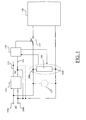
- Figure 1 depicts a schematic block diagram of part of an electric circuitry of a household appliance, for example, but not limitatively, a laundry washer.
- Reference numerals 105a and 105b denote two terminals which, in use, are plugged into an electricity main socket (not shown), for receiving the AC voltage (for example, terminal 105a is connected to a plug pin that is plugged to the AC socket port of the line voltage and terminal 105b is connected to a plug pin that is plugged to the AC socket port of the neutral); the AC voltage may for example be of 220V at 50 Hz nominal, or of 110V at 60 Hz nominal (other values are possible, depending on the standard adopted in a particular country).
- the AC voltage is fed to a voltage transformer and rectifying circuit 110, for generating one or more DC voltage values, distributed by DC voltage distribution lines 115 and 120, for example a 5V voltage for supplying a logic control unit 125, including for example a microprocessor or a microcontroller, controlling the operation of the appliance. Either one or the other of the DC voltage distribution lines 115 and 120 may be connected to the neutral (terminal 105b).
- Block 130 is intended to schematically represent all those parts of the appliance that are supplied by the AC voltage; such parts include for example the electric motor for rotating the laundry drum, the drain pump for discharging the washing/rinsing fluid, the electrovalve(s) for intaking water from a water main.
- the AC line voltage received at the terminal 105a is selectively fed to the parts schematized by block 130 through a main switch 135 (which may for example be the so-called "door-lock” switch), controlled by the control unit 125, which is closed only on condition that the appliance door (not depicted in the drawings) is correctly closed. In this way, it is ensured that, for safety purposes, the appliance cannot be started when the door is open, so as to prevent possible injuries.
- some of the parts schematized as included in block 130 downstream the main switch 135 may be moved upstream it; this may for example be the case of the drain pump 137, shown in phantom in Figure 1 , which, when placed upstream the main switch 135, can be operated for safety purposes to discharge the liquid present in the machine even in case the door is open.
- a heating circuit with monitoring arrangement 140 is provided, for heating the washing liquid for washing and/or rinse laundry.
- the heating circuit 140 is connected to the AC voltage terminals 105a, 105b upstream the main switch 135, i.e. one terminal 145a of the heating circuit 140 is connected to a conductor connected to the terminal 105a and carrying the line voltage, and the other terminal 145b is connected to the neutral terminal 105b.
- the operation of the heating circuit 140 is controlled by the control unit 125, which in addition monitors (through the monitoring arrangement) the heating circuit 140 for detecting possible faults, as will be described in greater detail in the following.
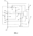
- FIG. 2 provides a more detailed view of the heating circuit 140 according to an embodiment of the present invention.
- the heating circuit 140 of the exemplary embodiment here considered comprises at least one heating resistor 205, connected in series with two switches 210a and 210b (a high-side switch 210a and a low-side switch 210b) between the voltage line connected to line voltage terminal 105a and, respectively, the neutral line connected to neutral terminal 105b.
- the heating resistor 205 is the element that, when energized, heats the washing liquid and/or the drying air flow.
- the switches 210a and 210b are for example relays, particularly monostable or alternatively bistable relays, which controlled, similarly to the door-lock switch 135, by the control unit 140.
- thermofuses may be provided at either one or both of the two terminals 215a and 215b of the heating resistor 205 , for protecting the heating resistor 205 against burning in case of overheating (in such a case, one or both of the thermofuses blow and thereby disconnect the heating resistor from the heating circuit); however, as will result clear from the following, the provision of the thermofuses is not strictly necessary.
- a first resistor R1 is connected in shunt between the terminals 215a and 215b of the heating resistor 205 that are connected to the switches 210a and 210b, respectively; the first resistor R1 has a resistance value (e.g., approximately 150 KOhms) substantially higher than the typical resistance of the heating resistor 205 (thus, when the heating resistor 205 functions properly, the overall resistance of the shunt connection essentially coincides with the resistance of the heating resistor 205).
- a second resistor R2 is connected between terminal 215b and the voltage line downstream the main switch 135.
- the control unit 125 is arranged to sense the voltage at the terminal 215a through a voltage divider circuit comprising a third resistor R3 connected between terminal 215a and a measuring input 235 of the control unit 125, and a fourth resistor R4 connected between the measuring input 235 and one of the two DC voltage distribution lines 115 and 120, namely to the DC voltage distribution line that is connected to the neutral.
- the control unit 125 is further arranged to sense the line voltage received at terminal 105a, for example through a resistive voltage partition network which may include one or two resistors 245, 246 connected between the line voltage and the neutral.
- control unit 125 When the appliance is plugged into the main voltage socket, the control unit 125 is energized.
- the control unit When the user input an appliance start command, conditioned to the fact that the door is assessed to be closed, the control unit commands the main switch 135 to close, thereby energizing the machine parts schematized in block 130.
- the control unit 125 commands the switches 210a and 210b to close. In this way, the heating resistor 205 is energized. Also in this case, the control unit 125 commands the switches 210a and 210b to close only conditioned to the fact that the appliance door is assessed to be closed.
- the control unit 125 is able to monitor the correct operation of the heating circuit and to detect possible faults thereof.
- the control unit 125 may be configured ( i.e . programmed) to perform a check sequence of the heating circuit for detecting possible failures of the components thereof.
- the control unit 125 periodically senses the line voltage value via the voltage partition network 245, 246 (e.g., every 20 - 80 milliseconds).
- the control unit 125 dynamically calculates and periodically updates (e.g., every 20 - 80 milliseconds) threshold values; such threshold values are dimensionless quantities which are calculated using a mathematical function implemented by the control unit 125. Similarly, the control unit 125 derives, from the voltage received at the measuring input 235, a dimensionless quantity that is compared to the dimensionless threshold values calculated on the basis of the detected line voltage. Based on the outcome of the comparison, the control unit 125 is capable of detecting faults in the heating circuit arrangement. It is pointed out that the threshold values changes as the line voltage change: thanks to this, account is taken of the actual value of the line voltage, which as known may differ from country to country, and is also subject to fluctuations in time. This makes the detection of the possible fault conditions more accurate and reliable.
- Table 1 provides an indication of how the voltage sensed at the measuring input 235, and thus the dimensionless value calculated by the control unit 125, changes depending on the status of the heating circuit arrangement and in case of different fault conditions.
- Table 1 shown underlined are indicative of fault conditions.
- the control unit 125 commands the main switch 135 and the other two switches 210a and 210b to be in the open condition (first row of Table 1)
- the voltage sensed by the control unit 125 at the input 235 should (in case of no faults) be low, close to earth (the third and fourth resistors R3 and R4 pull the terminal 215a to ground); in Table 1, the dimensionless value corresponding to an absence of faults is 0.
- a detected high value (corresponding to the value of the line voltage) of the voltage at the input 235 (and thus a high value of the dimensionless value derived therefrom) is thus indicative of the fact that the switch 210a does not operate properly and is blocked close ("glued close").
- the control unit 125 commands the door lock switch 135 to close, but keeping the other two switches 210a and 210b open, so as to keep the heating resistor 205 de-energized (second row in Table 1)
- the voltage sensed at the input 235 should, in case of no faults, be relatively high but less than the value of the line voltage: in fact, in this condition a resistive path should exist that, from the line connected to the line voltage terminal 105a, passes through the main switch 135, the second resistor R2, the shunt of the heating resistor 205 and the first resistor R1, the third resistor R3, the fourth resistor R4 and reaches the neutral.
- the dimensionless value corresponding to no faults is 170.
- the control unit 125 is capable of detecting and discriminating three possible faults:
- a no-fault condition corresponds to a high voltage value sensed at the input 235; in fact, in this condition the terminal 215a should be short-circuit to the line voltage.
- a very low value (close to ground) is in this case indicative of the fact that the switch 210a is "glued open” (or that there is a fault in the driving output of the control unit that drives the switch 210a. In fact, in this condition the terminal 215b is short-circuit to the neutral, and thus the voltage at the terminal 215a is low.
- the heating circuit described allows to discriminate whether a fault consists in the heating resistor being disconnected or in current leakages in the heating resistor; the first fault is not dangerous for the user's safety: it simply means that the washing liquid (or the drying air flow) cannot be heated; the second fault is instead potentially dangerous, because of dispersion currents.
- the machine cycle needs not be halted: the control unit 125 commands the two switches 210a and 210b to open and leaves the appliance to terminate the cycle.
- the heating circuit inclusive the elements necessary to properly monitor the heating circuit for possible faults, substantially does not involve stand-by power consumption.
- the main switch 135 and the two switches 210a and 210b are open, thus no conductive path exists between the line voltage and the neutral (also the resistive path including resistors R2, R1 in parallel to 205, R3 and R4 is disconnected from the line voltage); the only consumption is given by the resistive partition network 245, 246.
- the second resistor R2 may be connected to the terminal 215a of the heating resistor 205, and the measuring input 235 of the control unit 125 may be coupled to the terminal 215b.
Description
- The present invention relates in general to the field of household appliances, and more particularly to a heating circuit with monitoring arrangement for appliances like laundry washers, combined washers&dryers, dryers, dishwashers and the like, and in general for all those appliances wherein there is the necessity of heating a fluid (a washing liquid like in laundry washing machines or in dishwashers, or drying air like in laundry dryers).
- Heating circuits for household appliances like those listed above generally comprise a heating element consisting of a heating resistor and a switch element (e.g. a relay commanded by an appliance control unit or a level switch which closes only when a sufficient amount of liquid is present in the washing tub to ensure that the heating resistor is immersed) for energizing the heating resistor when required, for example in order to heat the washing liquid for washing laundry or dishes, or to heat the air flow used to dry the laundry.
- The heating circuit is generally monitored for assessing the proper operation and detecting possible faults thereof. Faults may as a matter of fact occur in the heating resistor or in the switch element energizing it. Usually, the heating circuit is monitored to identify whether the heating resistor is power on or off, or it is short-circuited to earth. Some of these faults may be extremely dangerous, for the appliance and even more for the user. For example, overheating of the heating resistor should be prevented, not to cause component parts to be damaged or destroyed, and fires to be produced; also, a heating resistor that occurs to be short-circuit to earth is a source of danger, because dispersion currents may reach the appliance cabinet and cause electrical shocks to the user. In case a fault of this type is detected, a decision is to be taken to halt the appliance.
- The Applicant has observed that known monitoring arrangements of the heating circuit are not capable of discriminating among different types of faults.
- Some faults may be classified as dangerous for the user's safety and thus lead to the appliance halt even if, actually, there would be no risk and the machine operation could be continued. This is undesirable, because the user has to wait for the intervention of the service personnel.
- Document
US 4 208 890 A shows a control circuit for controlling current supply to machines, such as a washing machine, the control circuit controlling the state of a first switch adapted to switch current to control means associated with the machine, functional means being monitored, such monitoring being operative to, should a fault occur, cause the first switch to open, and a back-up circuit, responsive to said monitors, including switching means operative to disconnect the current from the functional means if a fault occurs irrespective of the state of the first switch. - In view of the state of the art outlined above, it has been an object of the present invention to devise an improved heating circuit arrangement for a household appliance that guarantees a full monitoring and discrimination of essentially every possible fault.
- According to the present invention, there is provided washing and/or drying appliance, comprising a heating circuit for heating a washing liquid and/or a drying air flow, the heating circuit being connected to (AC) voltage distribution lines distributing (AC) power inside the appliance and comprising at least one heating resistor in series to switch means controlled by an appliance control unit for selectively energizing the heating resistor when required.
- The switch means of the heating circuit comprise a first and a second switches in series to the heating resistor, the heating resistor being interposed between the first and second switches.
- A monitoring circuit arrangement is provided, comprising a first resistor in shunt to the heating resistor and having a resistance substantially higher than that of the heating resistor, and a pull-up network connected between a first terminal of the heating resistor and one of the voltage distribution lines, the control unit being configured for receiving a voltage corresponding to an electric potential at a second terminal of the heating resistor.
- The appliance may further comprise a main switch controlled by the control unit for selectively allowing the powering of the appliance, and the heating circuit may be connected to the voltage supply lines upstream or downstream the main switch with respect to an AC voltage plug of the appliance.
- The main switch may be a switch switchable to close only conditioned to the fact that the control unit detects that an appliance door is closed.
- The pull-up network may be connected to the voltage distribution lines either downstream or upstream the main switch.
- The monitoring unit may further be configured for detecting a value of the voltage distributed by the voltage distribution lines and for comparing the detected value of the voltage distributed by the voltage distribution lines with the received voltage corresponding to the electric potential at the second terminal of the heating resistor.
- In particular, the monitoring unit may be configured for dynamically deriving, during the operation of the appliance, from the detected value of the voltage distributed by the voltage distribution lines at least one reference electric potential to be compared with the received voltage corresponding to the electric potential at the second terminal of the heating resistor.
- Said reference electric potential derived in dynamic way is preferably calculated periodically.
- These and other features and advantages of the present invention will appear more clearly by reading the following detailed description of an embodiment thereof, provided merely by way of non-limiting example, description that will be conducted making reference, for better intelligibility, to the attached drawings, wherein:
-
Figure 1 is a schematic block diagram of part of an electric circuitry of a household appliance, for example a laundry washer, with a heating circuit arrangement according to an embodiment of the present invention; and -
Figure 2 shows in greater detail the heating circuit arrangement ofFigure 1 . - Making reference to the drawings,
Figure 1 depicts a schematic block diagram of part of an electric circuitry of a household appliance, for example, but not limitatively, a laundry washer.Reference numerals terminal 105a is connected to a plug pin that is plugged to the AC socket port of the line voltage andterminal 105b is connected to a plug pin that is plugged to the AC socket port of the neutral); the AC voltage may for example be of 220V at 50 Hz nominal, or of 110V at 60 Hz nominal (other values are possible, depending on the standard adopted in a particular country). - The AC voltage is fed to a voltage transformer and rectifying
circuit 110, for generating one or more DC voltage values, distributed by DCvoltage distribution lines logic control unit 125, including for example a microprocessor or a microcontroller, controlling the operation of the appliance. Either one or the other of the DCvoltage distribution lines terminal 105b). -
Block 130 is intended to schematically represent all those parts of the appliance that are supplied by the AC voltage; such parts include for example the electric motor for rotating the laundry drum, the drain pump for discharging the washing/rinsing fluid, the electrovalve(s) for intaking water from a water main. The AC line voltage received at theterminal 105a is selectively fed to the parts schematized byblock 130 through a main switch 135 (which may for example be the so-called "door-lock" switch), controlled by thecontrol unit 125, which is closed only on condition that the appliance door (not depicted in the drawings) is correctly closed. In this way, it is ensured that, for safety purposes, the appliance cannot be started when the door is open, so as to prevent possible injuries. In alternative embodiments of the invention, some of the parts schematized as included inblock 130 downstream themain switch 135 may be moved upstream it; this may for example be the case of thedrain pump 137, shown in phantom inFigure 1 , which, when placed upstream themain switch 135, can be operated for safety purposes to discharge the liquid present in the machine even in case the door is open. - A heating circuit with
monitoring arrangement 140 is provided, for heating the washing liquid for washing and/or rinse laundry. According to an embodiment of the present invention, theheating circuit 140 is connected to theAC voltage terminals main switch 135, i.e. oneterminal 145a of theheating circuit 140 is connected to a conductor connected to theterminal 105a and carrying the line voltage, and theother terminal 145b is connected to theneutral terminal 105b. - The operation of the
heating circuit 140 is controlled by thecontrol unit 125, which in addition monitors (through the monitoring arrangement) theheating circuit 140 for detecting possible faults, as will be described in greater detail in the following. -
Figure 2 provides a more detailed view of theheating circuit 140 according to an embodiment of the present invention. Theheating circuit 140 of the exemplary embodiment here considered comprises at least oneheating resistor 205, connected in series with twoswitches side switch 210a and a low-side switch 210b) between the voltage line connected toline voltage terminal 105a and, respectively, the neutral line connected toneutral terminal 105b. Theheating resistor 205 is the element that, when energized, heats the washing liquid and/or the drying air flow. Theswitches lock switch 135, by thecontrol unit 140. One or two thermofuses may be provided at either one or both of the twoterminals heating resistor 205 , for protecting theheating resistor 205 against burning in case of overheating (in such a case, one or both of the thermofuses blow and thereby disconnect the heating resistor from the heating circuit); however, as will result clear from the following, the provision of the thermofuses is not strictly necessary. A first resistor R1 is connected in shunt between theterminals heating resistor 205 that are connected to theswitches heating resistor 205 functions properly, the overall resistance of the shunt connection essentially coincides with the resistance of the heating resistor 205). A second resistor R2 is connected betweenterminal 215b and the voltage line downstream themain switch 135. Thecontrol unit 125 is arranged to sense the voltage at theterminal 215a through a voltage divider circuit comprising a third resistor R3 connected betweenterminal 215a and ameasuring input 235 of thecontrol unit 125, and a fourth resistor R4 connected between themeasuring input 235 and one of the two DCvoltage distribution lines control unit 125 is further arranged to sense the line voltage received atterminal 105a, for example through a resistive voltage partition network which may include one or tworesistors - The heating circuit arrangement described in the foregoing operates as follows.
- When the appliance is plugged into the main voltage socket, the
control unit 125 is energized. - When the user input an appliance start command, conditioned to the fact that the door is assessed to be closed, the control unit commands the
main switch 135 to close, thereby energizing the machine parts schematized inblock 130. - In order to heat the washing fluid and/or the drying air flow, the
control unit 125 commands theswitches heating resistor 205 is energized. Also in this case, thecontrol unit 125 commands theswitches - The
control unit 125, thanks to the circuit arrangement shown, is able to monitor the correct operation of the heating circuit and to detect possible faults thereof. To do this, thecontrol unit 125 may be configured (i.e. programmed) to perform a check sequence of the heating circuit for detecting possible failures of the components thereof. - The
control unit 125 periodically senses the line voltage value via thevoltage partition network 245, 246 (e.g., every 20 - 80 milliseconds). - From the sensed value of the line voltage, the
control unit 125 dynamically calculates and periodically updates (e.g., every 20 - 80 milliseconds) threshold values; such threshold values are dimensionless quantities which are calculated using a mathematical function implemented by thecontrol unit 125. Similarly, thecontrol unit 125 derives, from the voltage received at themeasuring input 235, a dimensionless quantity that is compared to the dimensionless threshold values calculated on the basis of the detected line voltage. Based on the outcome of the comparison, thecontrol unit 125 is capable of detecting faults in the heating circuit arrangement. It is pointed out that the threshold values changes as the line voltage change: thanks to this, account is taken of the actual value of the line voltage, which as known may differ from country to country, and is also subject to fluctuations in time. This makes the detection of the possible fault conditions more accurate and reliable. - The table below (Table 1) provides an indication of how the voltage sensed at the
measuring input 235, and thus the dimensionless value calculated by thecontrol unit 125, changes depending on the status of the heating circuit arrangement and in case of different fault conditions. The values in Table 1 shown underlined are indicative of fault conditions.
- When the
control unit 125 commands themain switch 135 and the other twoswitches control unit 125 at theinput 235 should (in case of no faults) be low, close to earth (the third and fourth resistors R3 and R4 pull theterminal 215a to ground); in Table 1, the dimensionless value corresponding to an absence of faults is 0. A detected high value (corresponding to the value of the line voltage) of the voltage at the input 235 (and thus a high value of the dimensionless value derived therefrom) is thus indicative of the fact that theswitch 210a does not operate properly and is blocked close ("glued close"). - When the
control unit 125 commands thedoor lock switch 135 to close, but keeping the other twoswitches heating resistor 205 de-energized (second row in Table 1), the voltage sensed at theinput 235 should, in case of no faults, be relatively high but less than the value of the line voltage: in fact, in this condition a resistive path should exist that, from the line connected to theline voltage terminal 105a, passes through themain switch 135, the second resistor R2, the shunt of theheating resistor 205 and the first resistor R1, the third resistor R3, the fourth resistor R4 and reaches the neutral. In Table 1, the dimensionless value corresponding to no faults is 170. As shown in Table 1, based on the value of the voltage sensed at theinput 235, thecontrol unit 125 is capable of detecting and discriminating three possible faults: - a) a relatively high value (150 or less in Table 1), but sufficiently lower than the value (170) corresponding to the no-fault condition is indicative of the fact that the
heating resistor 205 is "open", i.e. non-conductive; in fact, in this case the resistance value of the shunt connection between theheating resistor 205 and the first resistor R1 essentially coincides with the resistance of the first resistor R1, which is substantially higher than the resistance of theheating resistor 205. This type of fault may depend on a malfunctioning of one or both of the thermofuses which may be provided at the terminals of theheating resistor 205, or a problem of theheating resistor 205. - b) a very low value (3 in Table 1), close to ground, is indicative of the fact that the
switch 210b is blocked closed ("glued close"); in fact, in this condition the terminal 215b is short-circuit to the neutral, and thus the voltage at the terminal 215a is low. - c) a high vale, corresponding to the line voltage (202 in Table 1) is indicative of the fact that the
switch 210a is blocked close ("glued close"); in fact, in this condition the terminal 215a is short-circuited to the line voltage.
When thecontrol unit 125 commands themain switch 135 to close, theswitch 210a to open and theswitch 210b to close (third row in Table 1), a no-fault condition correspond to a very low value sensed at the input 235 (corresponding to the dimensionless value 3 in Table 1); indeed, in this condition the terminal 215b is short-circuit to the neutral, and thus the voltage at the terminal 215a is low. As shown in Table 1, based on the value of the voltage sensed at theinput 235, thecontrol unit 125 is capable of detecting and discriminating two possible faults: - d) a first high voltage value (170 or less as indicated in Table 1) means that the
switch 210b is "glued open", or that there is a fault in the driving output of the control unit that drives theswitch 210b. - e) a second high vale, higher than the first high value and corresponding to the line voltage (202 in Table 1) is indicative of the fact that the
switch 210a is blocked close ("glued close"); in fact, in this condition the terminal 215a is short-circuited to the line voltage. - When, finally, the
control unit 125 commands all theswitches input 235; in fact, in this condition the terminal 215a should be short-circuit to the line voltage. A very low value (close to ground) is in this case indicative of the fact that theswitch 210a is "glued open" (or that there is a fault in the driving output of the control unit that drives theswitch 210a. In fact, in this condition the terminal 215b is short-circuit to the neutral, and thus the voltage at the terminal 215a is low. - The provision of the two
switches heating circuit 140, one upstream and the other downstream theheating resistor 205, makes theheating circuit 140 safer: also in case of faults in the heating resistor, by switching open the twoswitches - In particular, the heating circuit described allows to discriminate whether a fault consists in the heating resistor being disconnected or in current leakages in the heating resistor; the first fault is not dangerous for the user's safety: it simply means that the washing liquid (or the drying air flow) cannot be heated; the second fault is instead potentially dangerous, because of dispersion currents. In both cases, the machine cycle needs not be halted: the
control unit 125 commands the twoswitches - Thus, thanks to the circuit arrangement according to the described embodiment, it is possible to detect not only a failure of the
heating resistor 205 consisting in a short-circuit to the neutral, but also to detect if a failure involving the heating resistor is risky or acceptable. - An advantage of the described solution is that the heating circuit, inclusive the elements necessary to properly monitor the heating circuit for possible faults, substantially does not involve stand-by power consumption. In fact, when the appliance is not operating, the
main switch 135 and the twoswitches resistive partition network main switch 135, or, viceversa, connecting the heating circuit (heating resistor 205 andswitches main switch 135 and the second resistor R2 upstream, or moving allcircuit 140 downstream themain switch 135. - Clearly, those skilled in the art will be able to make several changes to the described invention embodiment, without departing from the scope of the invention defined in the appended claims.
- For example, the second resistor R2 may be connected to the terminal 215a of the
heating resistor 205, and the measuringinput 235 of thecontrol unit 125 may be coupled to the terminal 215b.
Claims (7)
- A washing and/or drying appliance, comprising a heating circuit (140) for heating a washing liquid and/or a drying air flow, the heating circuit being connected to voltage distribution lines (105a,105b) distributing power inside the appliance and comprising at least one heating resistor (205) connected to switch means (210a,210b) controlled by an appliance control unit (125) for selectively energizing the heating resistor when required, characterized in that:- the switch means of the heating circuit comprise a first switch (210a) connected to a first terminal (215a) of the heater resistor and a second switch (210b) connected to a second terminal (215b) of the heating resistor, the heating resistor being interposed between the first and second switches;- a monitoring circuit arrangement is provided, said monitoring circuit arrangement comprising a first resistor (R1) in shunt to the heating resistor and having a resistance substantially higher than that of the heating resistor, and a pull-up network connected between a first terminal (215b;215a) of the heating resistor and one of the voltage distribution lines, the control unit being configured for receiving a voltage corresponding to an electric potential at a second terminal (215a;215b) of the heating resistor.
- The appliance of claim 1, further comprising a main switch (135) controlled by the control unit (125) for selectively allowing the powering of the appliance, wherein the heating circuit is connected to the voltage supply lines upstream or downstream the main switch with respect to an AC voltage plug of the appliance.
- The appliance of claim 2, wherein said main switch (135) is switchable to close only conditioned to the fact that the control unit (125) detects that an appliance door is closed.
- The appliance of claim 2 or 3, wherein said pull-up network is connected to said voltage distribution lines either downstream or upstream the main switch (135).
- The appliance of any one of the preceding claims, wherein the control unit is further configured for detecting a value of the voltage distributed by the voltage distribution lines and for comparing the detected value of the voltage distributed by the voltage distribution lines with the received voltage corresponding to the electric potential at the second terminal (215a, 215b) of the heating resistor.
- The appliance according to claim 5, in which the control unit (125) is configured for dynamically deriving, during the operation of the appliance, from the detected value of the voltage distributed by the voltage distribution lines at least one reference electric potential to be compared with the received voltage corresponding to the electric potential at the second terminal of the heating resistor (205).
- The appliance according to claim 6, in which said reference electric potential derived in dynamic way is calculated periodically.
Priority Applications (1)
| Application Number | Priority Date | Filing Date | Title |
|---|---|---|---|
| EP11721734.9A EP2569477B1 (en) | 2010-05-14 | 2011-05-12 | Heating circuit with monitoring arrangement for a household appliance |
Applications Claiming Priority (3)
| Application Number | Priority Date | Filing Date | Title |
|---|---|---|---|
| EP10162838.6A EP2386680B1 (en) | 2010-05-14 | 2010-05-14 | Heating circuit with monitoring arrangement for a household appliance |
| EP11721734.9A EP2569477B1 (en) | 2010-05-14 | 2011-05-12 | Heating circuit with monitoring arrangement for a household appliance |
| PCT/EP2011/057712 WO2011141555A1 (en) | 2010-05-14 | 2011-05-12 | Heating circuit with monitoring arrangement for a household appliance |
Publications (2)
| Publication Number | Publication Date |
|---|---|
| EP2569477A1 EP2569477A1 (en) | 2013-03-20 |
| EP2569477B1 true EP2569477B1 (en) | 2014-06-18 |
Family
ID=42983960
Family Applications (2)
| Application Number | Title | Priority Date | Filing Date |
|---|---|---|---|
| EP10162838.6A Active EP2386680B1 (en) | 2010-05-14 | 2010-05-14 | Heating circuit with monitoring arrangement for a household appliance |
| EP11721734.9A Active EP2569477B1 (en) | 2010-05-14 | 2011-05-12 | Heating circuit with monitoring arrangement for a household appliance |
Family Applications Before (1)
| Application Number | Title | Priority Date | Filing Date |
|---|---|---|---|
| EP10162838.6A Active EP2386680B1 (en) | 2010-05-14 | 2010-05-14 | Heating circuit with monitoring arrangement for a household appliance |
Country Status (7)
| Country | Link |
|---|---|
| US (1) | US8869426B2 (en) |
| EP (2) | EP2386680B1 (en) |
| CN (1) | CN103003483B (en) |
| AU (1) | AU2011251975B2 (en) |
| BR (1) | BR112012029049B1 (en) |
| RU (1) | RU2570364C2 (en) |
| WO (1) | WO2011141555A1 (en) |
Families Citing this family (8)
| Publication number | Priority date | Publication date | Assignee | Title |
|---|---|---|---|---|
| EP2386680B1 (en) * | 2010-05-14 | 2014-06-04 | Electrolux Home Products Corporation N.V. | Heating circuit with monitoring arrangement for a household appliance |
| EP2386675B1 (en) | 2010-05-14 | 2014-07-16 | Electrolux Home Products Corporation N.V. | Heating circuit with monitoring arrangement for a household appliance |
| ITMI20100862A1 (en) | 2010-05-14 | 2011-11-15 | Electrolux Home Products Corporatio N N V | MONITORING OF FAILURES IN THE HEATING CIRCUIT OF A HOUSEHOLD APPLIANCE |
| FR3009000B1 (en) * | 2013-07-24 | 2015-08-14 | Fagorbrandt Sas | HOUSEHOLD APPLIANCE COMPRISING AT LEAST ONE LOAD |
| PL3080622T3 (en) | 2013-12-09 | 2023-02-13 | Electrolux Appliances Aktiebolag | Method and circuit for determining faults in appliances |
| DE102013226833A1 (en) * | 2013-12-20 | 2015-06-25 | BSH Hausgeräte GmbH | Home appliance and monitoring method for a household appliance |
| EP3177104B1 (en) * | 2015-12-02 | 2018-09-19 | Whirlpool Corporation | Diagnostic method for an electric heater |
| EP3582584A1 (en) | 2018-06-12 | 2019-12-18 | Continental Automotive GmbH | Electric circuit and diagnostic method for an electric load |
Family Cites Families (30)
| Publication number | Priority date | Publication date | Assignee | Title |
|---|---|---|---|---|
| US2851790A (en) * | 1955-11-25 | 1958-09-16 | Gen Electric | Temperature control means for clothes dryer |
| US3112187A (en) * | 1960-08-04 | 1963-11-26 | Gen Electric | Control system for clothes dryers |
| US3180038A (en) * | 1962-01-26 | 1965-04-27 | Gen Electric | Automatic dryer control circuit |
| US3409994A (en) * | 1966-09-15 | 1968-11-12 | Gen Motors Corp | Heating control system for clothes dryer |
| US3475830A (en) * | 1967-10-20 | 1969-11-04 | Texas Instruments Inc | Dryer control |
| US3609873A (en) * | 1970-05-08 | 1971-10-05 | Whirlpool Co | Control circuit to deactivate an appliance |
| US3942265A (en) * | 1974-05-09 | 1976-03-09 | General Electric Company | Dryer control arrangement |
| CA1024240A (en) * | 1974-10-10 | 1978-01-10 | Gsw Limited - Gsw Limitee | Automatic regulation of drying time in a clothes drying machine |
| US4083118A (en) * | 1976-09-07 | 1978-04-11 | The Maytag Company | Time-and-temperature dryer control |
| US4208890A (en) * | 1977-09-26 | 1980-06-24 | Servis Domestic Appliances Limited | Control circuits in or for washing, drying and the like machines or other apparatus |
| US4642907A (en) * | 1985-10-22 | 1987-02-17 | Whirlpool Corporation | Thermal bias and timer run-out for automatic dryer control |
| US5281956A (en) | 1989-08-11 | 1994-01-25 | Whirlpool Corporation | Heater diagnostics and electronic control for a clothes dryer |
| RU2030124C1 (en) * | 1992-07-17 | 1995-02-27 | Товарищество с ограниченной ответственностью "Электрет" | Electric heater for preparation of hot liquid |
| JPH0924197A (en) | 1995-07-10 | 1997-01-28 | Matsushita Electric Ind Co Ltd | Clothing drying machine |
| RU2105433C1 (en) * | 1996-01-03 | 1998-02-20 | Акционерное общество открытого типа "СЭВ" | Electric water heater |
| DE19755089C2 (en) | 1997-12-11 | 2003-07-03 | Whirlpool Co | Safety circuit for a heating circuit in a washing machine, dishwasher or dryer |
| US6079121A (en) * | 1998-08-03 | 2000-06-27 | Ther-O-Disc, Incorporated | Humidity-modulated dual-setpoint temperature controller |
| RU2160920C2 (en) * | 1998-08-12 | 2000-12-20 | Научно-исследовательский институт точных приборов | Temperature controller |
| US6064043A (en) * | 1999-06-01 | 2000-05-16 | France/Scott Fetzer Company | Dryer control circuit |
| US6246831B1 (en) | 1999-06-16 | 2001-06-12 | David Seitz | Fluid heating control system |
| DE102005029921A1 (en) * | 2005-06-22 | 2007-01-04 | BSH Bosch und Siemens Hausgeräte GmbH | Heating device for fluids and household appliance |
| US8015726B2 (en) * | 2005-06-23 | 2011-09-13 | Whirlpool Corporation | Automatic clothes dryer |
| EP1744248A1 (en) | 2005-07-11 | 2007-01-17 | WRAP S.p.A. | Device for monitoring an electric appliance |
| US7594343B2 (en) * | 2006-02-14 | 2009-09-29 | Whirlpool Corporation | Drying mode for automatic clothes dryer |
| DE102008006512A1 (en) | 2008-01-29 | 2009-07-30 | BSH Bosch und Siemens Hausgeräte GmbH | Circuit arrangement for operating a domestic appliance and corresponding method |
| CN101865527A (en) * | 2009-04-14 | 2010-10-20 | 广东松下环境系统有限公司 | Air heating apparatus and control method for preventing same from overheating |
| EP2386680B1 (en) * | 2010-05-14 | 2014-06-04 | Electrolux Home Products Corporation N.V. | Heating circuit with monitoring arrangement for a household appliance |
| EP2386675B1 (en) * | 2010-05-14 | 2014-07-16 | Electrolux Home Products Corporation N.V. | Heating circuit with monitoring arrangement for a household appliance |
| ITMI20100862A1 (en) * | 2010-05-14 | 2011-11-15 | Electrolux Home Products Corporatio N N V | MONITORING OF FAILURES IN THE HEATING CIRCUIT OF A HOUSEHOLD APPLIANCE |
| CN201758386U (en) * | 2010-07-23 | 2011-03-09 | 余兴辉 | Alarm control circuit for heating devices of tunnel drier |
-
2010
- 2010-05-14 EP EP10162838.6A patent/EP2386680B1/en active Active
-
2011
- 2011-05-12 CN CN201180023917.8A patent/CN103003483B/en active Active
- 2011-05-12 US US13/697,838 patent/US8869426B2/en active Active
- 2011-05-12 RU RU2012154060/07A patent/RU2570364C2/en active
- 2011-05-12 EP EP11721734.9A patent/EP2569477B1/en active Active
- 2011-05-12 BR BR112012029049A patent/BR112012029049B1/en active IP Right Grant
- 2011-05-12 AU AU2011251975A patent/AU2011251975B2/en active Active
- 2011-05-12 WO PCT/EP2011/057712 patent/WO2011141555A1/en active Application Filing
Also Published As
| Publication number | Publication date |
|---|---|
| CN103003483B (en) | 2015-08-19 |
| BR112012029049B1 (en) | 2020-04-07 |
| EP2569477A1 (en) | 2013-03-20 |
| CN103003483A (en) | 2013-03-27 |
| WO2011141555A1 (en) | 2011-11-17 |
| AU2011251975B2 (en) | 2015-01-15 |
| RU2012154060A (en) | 2014-06-20 |
| US8869426B2 (en) | 2014-10-28 |
| AU2011251975A1 (en) | 2012-12-06 |
| RU2570364C2 (en) | 2015-12-10 |
| EP2386680B1 (en) | 2014-06-04 |
| EP2386680A1 (en) | 2011-11-16 |
| US20130061488A1 (en) | 2013-03-14 |
| BR112012029049A2 (en) | 2016-08-02 |
Similar Documents
| Publication | Publication Date | Title |
|---|---|---|
| US10136473B2 (en) | Heating circuit with monitoring arrangement for a household appliance | |
| EP2569477B1 (en) | Heating circuit with monitoring arrangement for a household appliance | |
| EP2386806B1 (en) | Monitoring faults in the heating circuit of an appliance | |
| AU2019201672B2 (en) | Electric grill with current protection circuitry | |
| CN105264392B (en) | For the determining method that electrical power is earthward disperseed in electric appliance and circuit | |
| EP0924331B1 (en) | Safety circuit for a heating circuit of a washing machine, dishwasher or drier | |
| US20140285929A1 (en) | Ground Power Leakage Detection for Peripheral Printed Circuit Boards | |
| EP2416226B1 (en) | Washing machine having alternatively operating electric loads | |
| EP3095911B1 (en) | Method for safely managing electric motor activation and deactivation, and corresponding appliance |
Legal Events
| Date | Code | Title | Description |
|---|---|---|---|
| PUAI | Public reference made under article 153(3) epc to a published international application that has entered the european phase |
Free format text: ORIGINAL CODE: 0009012 |
|
| 17P | Request for examination filed |
Effective date: 20121214 |
|
| AK | Designated contracting states |
Kind code of ref document: A1 Designated state(s): AL AT BE BG CH CY CZ DE DK EE ES FI FR GB GR HR HU IE IS IT LI LT LU LV MC MK MT NL NO PL PT RO RS SE SI SK SM TR |
|
| DAX | Request for extension of the european patent (deleted) | ||
| GRAP | Despatch of communication of intention to grant a patent |
Free format text: ORIGINAL CODE: EPIDOSNIGR1 |
|
| INTG | Intention to grant announced |
Effective date: 20140108 |
|
| GRAS | Grant fee paid |
Free format text: ORIGINAL CODE: EPIDOSNIGR3 |
|
| GRAA | (expected) grant |
Free format text: ORIGINAL CODE: 0009210 |
|
| AK | Designated contracting states |
Kind code of ref document: B1 Designated state(s): AL AT BE BG CH CY CZ DE DK EE ES FI FR GB GR HR HU IE IS IT LI LT LU LV MC MK MT NL NO PL PT RO RS SE SI SK SM TR |
|
| REG | Reference to a national code |
Ref country code: GB Ref legal event code: FG4D |
|
| REG | Reference to a national code |
Ref country code: CH Ref legal event code: EP |
|
| REG | Reference to a national code |
Ref country code: AT Ref legal event code: REF Ref document number: 673447 Country of ref document: AT Kind code of ref document: T Effective date: 20140715 |
|
| REG | Reference to a national code |
Ref country code: IE Ref legal event code: FG4D |
|
| REG | Reference to a national code |
Ref country code: DE Ref legal event code: R096 Ref document number: 602011007792 Country of ref document: DE Effective date: 20140731 |
|
| PG25 | Lapsed in a contracting state [announced via postgrant information from national office to epo] |
Ref country code: GR Free format text: LAPSE BECAUSE OF FAILURE TO SUBMIT A TRANSLATION OF THE DESCRIPTION OR TO PAY THE FEE WITHIN THE PRESCRIBED TIME-LIMIT Effective date: 20140919 Ref country code: CY Free format text: LAPSE BECAUSE OF FAILURE TO SUBMIT A TRANSLATION OF THE DESCRIPTION OR TO PAY THE FEE WITHIN THE PRESCRIBED TIME-LIMIT Effective date: 20140618 Ref country code: LT Free format text: LAPSE BECAUSE OF FAILURE TO SUBMIT A TRANSLATION OF THE DESCRIPTION OR TO PAY THE FEE WITHIN THE PRESCRIBED TIME-LIMIT Effective date: 20140618 Ref country code: FI Free format text: LAPSE BECAUSE OF FAILURE TO SUBMIT A TRANSLATION OF THE DESCRIPTION OR TO PAY THE FEE WITHIN THE PRESCRIBED TIME-LIMIT Effective date: 20140618 Ref country code: NO Free format text: LAPSE BECAUSE OF FAILURE TO SUBMIT A TRANSLATION OF THE DESCRIPTION OR TO PAY THE FEE WITHIN THE PRESCRIBED TIME-LIMIT Effective date: 20140918 |
|
| REG | Reference to a national code |
Ref country code: NL Ref legal event code: VDEP Effective date: 20140618 |
|
| REG | Reference to a national code |
Ref country code: AT Ref legal event code: MK05 Ref document number: 673447 Country of ref document: AT Kind code of ref document: T Effective date: 20140618 |
|
| REG | Reference to a national code |
Ref country code: LT Ref legal event code: MG4D |
|
| PG25 | Lapsed in a contracting state [announced via postgrant information from national office to epo] |
Ref country code: HR Free format text: LAPSE BECAUSE OF FAILURE TO SUBMIT A TRANSLATION OF THE DESCRIPTION OR TO PAY THE FEE WITHIN THE PRESCRIBED TIME-LIMIT Effective date: 20140618 Ref country code: LV Free format text: LAPSE BECAUSE OF FAILURE TO SUBMIT A TRANSLATION OF THE DESCRIPTION OR TO PAY THE FEE WITHIN THE PRESCRIBED TIME-LIMIT Effective date: 20140618 Ref country code: SE Free format text: LAPSE BECAUSE OF FAILURE TO SUBMIT A TRANSLATION OF THE DESCRIPTION OR TO PAY THE FEE WITHIN THE PRESCRIBED TIME-LIMIT Effective date: 20140618 Ref country code: RS Free format text: LAPSE BECAUSE OF FAILURE TO SUBMIT A TRANSLATION OF THE DESCRIPTION OR TO PAY THE FEE WITHIN THE PRESCRIBED TIME-LIMIT Effective date: 20140618 |
|
| PG25 | Lapsed in a contracting state [announced via postgrant information from national office to epo] |
Ref country code: CZ Free format text: LAPSE BECAUSE OF FAILURE TO SUBMIT A TRANSLATION OF THE DESCRIPTION OR TO PAY THE FEE WITHIN THE PRESCRIBED TIME-LIMIT Effective date: 20140618 Ref country code: PT Free format text: LAPSE BECAUSE OF FAILURE TO SUBMIT A TRANSLATION OF THE DESCRIPTION OR TO PAY THE FEE WITHIN THE PRESCRIBED TIME-LIMIT Effective date: 20141020 Ref country code: SK Free format text: LAPSE BECAUSE OF FAILURE TO SUBMIT A TRANSLATION OF THE DESCRIPTION OR TO PAY THE FEE WITHIN THE PRESCRIBED TIME-LIMIT Effective date: 20140618 Ref country code: RO Free format text: LAPSE BECAUSE OF FAILURE TO SUBMIT A TRANSLATION OF THE DESCRIPTION OR TO PAY THE FEE WITHIN THE PRESCRIBED TIME-LIMIT Effective date: 20140618 Ref country code: EE Free format text: LAPSE BECAUSE OF FAILURE TO SUBMIT A TRANSLATION OF THE DESCRIPTION OR TO PAY THE FEE WITHIN THE PRESCRIBED TIME-LIMIT Effective date: 20140618 Ref country code: ES Free format text: LAPSE BECAUSE OF FAILURE TO SUBMIT A TRANSLATION OF THE DESCRIPTION OR TO PAY THE FEE WITHIN THE PRESCRIBED TIME-LIMIT Effective date: 20140618 |
|
| PG25 | Lapsed in a contracting state [announced via postgrant information from national office to epo] |
Ref country code: PL Free format text: LAPSE BECAUSE OF FAILURE TO SUBMIT A TRANSLATION OF THE DESCRIPTION OR TO PAY THE FEE WITHIN THE PRESCRIBED TIME-LIMIT Effective date: 20140618 Ref country code: IS Free format text: LAPSE BECAUSE OF FAILURE TO SUBMIT A TRANSLATION OF THE DESCRIPTION OR TO PAY THE FEE WITHIN THE PRESCRIBED TIME-LIMIT Effective date: 20141018 Ref country code: NL Free format text: LAPSE BECAUSE OF FAILURE TO SUBMIT A TRANSLATION OF THE DESCRIPTION OR TO PAY THE FEE WITHIN THE PRESCRIBED TIME-LIMIT Effective date: 20140618 Ref country code: AT Free format text: LAPSE BECAUSE OF FAILURE TO SUBMIT A TRANSLATION OF THE DESCRIPTION OR TO PAY THE FEE WITHIN THE PRESCRIBED TIME-LIMIT Effective date: 20140618 |
|
| REG | Reference to a national code |
Ref country code: DE Ref legal event code: R097 Ref document number: 602011007792 Country of ref document: DE |
|
| PLBE | No opposition filed within time limit |
Free format text: ORIGINAL CODE: 0009261 |
|
| STAA | Information on the status of an ep patent application or granted ep patent |
Free format text: STATUS: NO OPPOSITION FILED WITHIN TIME LIMIT |
|
| PG25 | Lapsed in a contracting state [announced via postgrant information from national office to epo] |
Ref country code: DK Free format text: LAPSE BECAUSE OF FAILURE TO SUBMIT A TRANSLATION OF THE DESCRIPTION OR TO PAY THE FEE WITHIN THE PRESCRIBED TIME-LIMIT Effective date: 20140618 |
|
| 26N | No opposition filed |
Effective date: 20150319 |
|
| PG25 | Lapsed in a contracting state [announced via postgrant information from national office to epo] |
Ref country code: BE Free format text: LAPSE BECAUSE OF FAILURE TO SUBMIT A TRANSLATION OF THE DESCRIPTION OR TO PAY THE FEE WITHIN THE PRESCRIBED TIME-LIMIT Effective date: 20140618 |
|
| REG | Reference to a national code |
Ref country code: DE Ref legal event code: R097 Ref document number: 602011007792 Country of ref document: DE Effective date: 20150319 |
|
| PG25 | Lapsed in a contracting state [announced via postgrant information from national office to epo] |
Ref country code: SI Free format text: LAPSE BECAUSE OF FAILURE TO SUBMIT A TRANSLATION OF THE DESCRIPTION OR TO PAY THE FEE WITHIN THE PRESCRIBED TIME-LIMIT Effective date: 20140618 |
|
| REG | Reference to a national code |
Ref country code: CH Ref legal event code: PL |
|
| PG25 | Lapsed in a contracting state [announced via postgrant information from national office to epo] |
Ref country code: LU Free format text: LAPSE BECAUSE OF FAILURE TO SUBMIT A TRANSLATION OF THE DESCRIPTION OR TO PAY THE FEE WITHIN THE PRESCRIBED TIME-LIMIT Effective date: 20150512 Ref country code: CH Free format text: LAPSE BECAUSE OF NON-PAYMENT OF DUE FEES Effective date: 20150531 Ref country code: LI Free format text: LAPSE BECAUSE OF NON-PAYMENT OF DUE FEES Effective date: 20150531 Ref country code: MC Free format text: LAPSE BECAUSE OF FAILURE TO SUBMIT A TRANSLATION OF THE DESCRIPTION OR TO PAY THE FEE WITHIN THE PRESCRIBED TIME-LIMIT Effective date: 20140618 |
|
| REG | Reference to a national code |
Ref country code: IE Ref legal event code: MM4A |
|
| PG25 | Lapsed in a contracting state [announced via postgrant information from national office to epo] |
Ref country code: IE Free format text: LAPSE BECAUSE OF NON-PAYMENT OF DUE FEES Effective date: 20150512 |
|
| REG | Reference to a national code |
Ref country code: FR Ref legal event code: PLFP Year of fee payment: 6 |
|
| PG25 | Lapsed in a contracting state [announced via postgrant information from national office to epo] |
Ref country code: MT Free format text: LAPSE BECAUSE OF FAILURE TO SUBMIT A TRANSLATION OF THE DESCRIPTION OR TO PAY THE FEE WITHIN THE PRESCRIBED TIME-LIMIT Effective date: 20140618 |
|
| REG | Reference to a national code |
Ref country code: FR Ref legal event code: PLFP Year of fee payment: 7 |
|
| PG25 | Lapsed in a contracting state [announced via postgrant information from national office to epo] |
Ref country code: SM Free format text: LAPSE BECAUSE OF FAILURE TO SUBMIT A TRANSLATION OF THE DESCRIPTION OR TO PAY THE FEE WITHIN THE PRESCRIBED TIME-LIMIT Effective date: 20140618 Ref country code: BG Free format text: LAPSE BECAUSE OF FAILURE TO SUBMIT A TRANSLATION OF THE DESCRIPTION OR TO PAY THE FEE WITHIN THE PRESCRIBED TIME-LIMIT Effective date: 20140618 Ref country code: HU Free format text: LAPSE BECAUSE OF FAILURE TO SUBMIT A TRANSLATION OF THE DESCRIPTION OR TO PAY THE FEE WITHIN THE PRESCRIBED TIME-LIMIT; INVALID AB INITIO Effective date: 20110512 |
|
| PG25 | Lapsed in a contracting state [announced via postgrant information from national office to epo] |
Ref country code: TR Free format text: LAPSE BECAUSE OF FAILURE TO SUBMIT A TRANSLATION OF THE DESCRIPTION OR TO PAY THE FEE WITHIN THE PRESCRIBED TIME-LIMIT Effective date: 20140618 |
|
| REG | Reference to a national code |
Ref country code: FR Ref legal event code: PLFP Year of fee payment: 8 |
|
| PG25 | Lapsed in a contracting state [announced via postgrant information from national office to epo] |
Ref country code: MK Free format text: LAPSE BECAUSE OF FAILURE TO SUBMIT A TRANSLATION OF THE DESCRIPTION OR TO PAY THE FEE WITHIN THE PRESCRIBED TIME-LIMIT Effective date: 20140618 |
|
| PG25 | Lapsed in a contracting state [announced via postgrant information from national office to epo] |
Ref country code: AL Free format text: LAPSE BECAUSE OF FAILURE TO SUBMIT A TRANSLATION OF THE DESCRIPTION OR TO PAY THE FEE WITHIN THE PRESCRIBED TIME-LIMIT Effective date: 20140618 |
|
| PGFP | Annual fee paid to national office [announced via postgrant information from national office to epo] |
Ref country code: IT Payment date: 20220524 Year of fee payment: 12 Ref country code: GB Payment date: 20220520 Year of fee payment: 12 Ref country code: FR Payment date: 20220523 Year of fee payment: 12 Ref country code: DE Payment date: 20220519 Year of fee payment: 12 |
|
| REG | Reference to a national code |
Ref country code: DE Ref legal event code: R119 Ref document number: 602011007792 Country of ref document: DE |
|
| GBPC | Gb: european patent ceased through non-payment of renewal fee |
Effective date: 20230512 |