EP2568836B1 - Headgear support device having front-back adjustment - Google Patents
Headgear support device having front-back adjustment Download PDFInfo
- Publication number
- EP2568836B1 EP2568836B1 EP11722142.4A EP11722142A EP2568836B1 EP 2568836 B1 EP2568836 B1 EP 2568836B1 EP 11722142 A EP11722142 A EP 11722142A EP 2568836 B1 EP2568836 B1 EP 2568836B1
- Authority
- EP
- European Patent Office
- Prior art keywords
- pivot
- face shield
- slot
- pivot element
- face
- Prior art date
- Legal status (The legal status is an assumption and is not a legal conclusion. Google has not performed a legal analysis and makes no representation as to the accuracy of the status listed.)
- Not-in-force
Links
- 230000001681 protective effect Effects 0.000 description 9
- 230000008878 coupling Effects 0.000 description 2
- 238000010168 coupling process Methods 0.000 description 2
- 238000005859 coupling reaction Methods 0.000 description 2
- 238000010276 construction Methods 0.000 description 1
- 238000003466 welding Methods 0.000 description 1
Images


Classifications
-
- A—HUMAN NECESSITIES
- A42—HEADWEAR
- A42C—MANUFACTURING OR TRIMMING HEAD COVERINGS, e.g. HATS
- A42C5/00—Fittings or trimmings for hats, e.g. hat-bands
-
- A—HUMAN NECESSITIES
- A42—HEADWEAR
- A42B—HATS; HEAD COVERINGS
- A42B3/00—Helmets; Helmet covers ; Other protective head coverings
- A42B3/04—Parts, details or accessories of helmets
-
- A—HUMAN NECESSITIES
- A42—HEADWEAR
- A42B—HATS; HEAD COVERINGS
- A42B3/00—Helmets; Helmet covers ; Other protective head coverings
- A42B3/04—Parts, details or accessories of helmets
- A42B3/18—Face protection devices
- A42B3/22—Visors
- A42B3/221—Attaching visors to helmet shells, e.g. on motorcycle helmets
-
- A—HUMAN NECESSITIES
- A42—HEADWEAR
- A42B—HATS; HEAD COVERINGS
- A42B3/00—Helmets; Helmet covers ; Other protective head coverings
- A42B3/04—Parts, details or accessories of helmets
- A42B3/18—Face protection devices
- A42B3/22—Visors
- A42B3/225—Visors with full face protection, e.g. for industrial safety applications
Definitions
- This invention relates to headgear support device for use with protective headgear having a face shield, and more particularly, a headgear support device which provides front-back adjustment.
- Protective headgear typically includes headgear supports with headbands or head straps that are adjustable to provide the headgear with a comfortable fit on a wide range of head sizes.
- the headgear may also include a visor or mask shell which serves to protect the user.
- the visor is typically rotatably mounted onto a helmet or other protective headgear to enable rotation of the visor up and away from the user's face. It has been found such visors provide discomfort to the user when the visor is in the down position. Therefore, it would be desirable to provide a headgear arrangement which provides greater comfort to the user.
- a headgear support device for supporting a visor includes a headband having an elongated slot and a pivot element which is affixed to the visor or mask shell.
- the pivot element is slidably located within the slot to enable translational movement of the visor or mask shell.
- the pivot element is also rotatable within the slot to enable rotational movement of the visor or mask shell.
- the device also includes a retaining element for retaining the pivot element in the slot to enable translational movement of the pivot element and visor.
- US 2007/0245467 upon which the pre-characterising portion of claim 1 is based, discloses a headgear support device for supporting a face shield comprising: a headband having an elongated slot; and a pivot element affixed to a visor, wherein the pivot element is slidably located within the slot to enable translational movement of the face shield and wherein the pivot element is also rotatable within the slot to enable rotational movement of the face shield.
- a head gear support device as defined in claim 1.
- a head top support system 10 which is constructed in three sectional pieces.
- the system 10 includes an overhead support band 14, a frontal head support band 16 and a rear head support band 18.
- the overhead support band 14 and rear head support band 18 moves independently relative to the frontal head support band 16.
- the three section headgear support is designed to be used with a variety of different types of protective headgear.
- Representative functional protective structures include welding, brow guard face protection visor, air fed face shield, combinations of these structures, and the like.
- the overhead support band 14 is positioned approximately ninety degrees from the frontal head support band 16.
- the overhead support band 14, frontal head support band 16 and rear head support band 18 are connected at a first and second common connection area.
- the common connection area allows the three sections to move relative to each other while maintaining restrictions within that movement.
- the overhead support band 14 preferably has an angular range of movement of from about ten degrees or less from the frontal head support band 16. This range of movement allows proper adjustment of the system 10 on the head of the wearer of the protective head covering while permitting balance and comfortable fit of the protective head covering.
- the rear head support band 18 has an angular range of movement of from about forty-five degrees or less relative to the overhead support band 14, allowing the rear support band 18 to properly adjust at the base of the back of the user's head.
- both the overhead support band 14 and rear support band 18 include a length changing mechanism.
- a ratchet mechanism is preferred and used to ensure that the rear support band 18 is inhibited from moving too far up the user's head, regardless of size, which would compromise the reliability of the user to retain the protective head covering during use. Length adjustment of the overhead support band 14 allows proper fitting of the system 10 on multiple users with different head sizes.
- the device 100 includes a headband 106 for accommodating a user's head (only a portion of the headband 106 is shown).
- the headband 106 includes a pivot stud 120 which is located within an elongated slot 103.
- the pivot stud 120 is slidable within the slot 103.
- translational movement of the pivot stud 120 toward a front end 105 of the slot 103 moves a mask or visor shell either further from a user's face.
- translational movement of the pivot stud 120 towards a rear end 107 of the slot 103 moves the visor closer to a user's face.
- the translation movement of the pivot stud 120 is shown by arrow 200 to denote front to back adjustment.
- a user may adjust the visor as desired in order to provide greater comfort.
- the range of the front to back adjustment is approximately 25 mm.
- Top 109 and bottom 111 portions of a perimeter portion 113 of the slot 103 include a plurality of spaced apart sunken or subsurface portions which serve as adjustment stops 110.
- the adjustment stops 110 offer guidance to a user regarding a position of a visor or mask shell (collectively referred to as a face shield) relative to the user's face.
- the pivot stud 120 further includes a round shoulder 115 which rotates relative to an inner surface 117 of the perimeter portion 113 to also enable rotation of the pivot stud 120 relative to the headband 106.
- the headgear support device 100 further includes a pivot link 132 (shown in a semi-transparent view) which is located on the pivot stud 120.
- a rear portion of the pivot link 132 is shown.
- the pivot link 132 includes a hole 133 which is adapted to mount on the round shoulder 115 of the pivot stud 120.
- the pivot link 132 includes upper 135 and lower 137 guide elements which fit over and accommodate the top 109 and bottom 111 portions of the perimeter portion 113 to thus enable the pivot stud 120 to slide within the slot 103.
- An internal surface of the pivot link 132 includes raised portions 130 (shown in Fig. 3a ) which serve to engage with the sunken or sub surfaces of the adjustment stops 110 to thus locate the pivot stud 120 in the slot 103 relative to the headband 106.
- the headgear support device 100 also includes a pivot stop 140 located in a substantially vertical position.
- the pivot stop 140 is attached to a mask or visor shell of a helmet or other protective headgear.
- the pivot stop 140 includes a hole 141 for accommodating the round shoulder 115 of the pivot stud 120 to enable rotation of the pivot stop 140 and thus the mask or visor shell relative to the headgear 106.
- the pivot stop 140 includes upper 143 and lower 145 recesses having a substantially semicircular shape for accommodating a stationary location peg 128 which extends from the pivot link 132. In Fig. 4 , the peg 128 is shown located within the upper recess 143 to thus stop rotation of the visor when the face shield is in the down position.
- the pivot stop 140 is shown rotated in a substantially horizontal position wherein the face shield is in the up (raised) position. In this position, the peg 128 is received in the lower recess 145 to thus stop rotation of the face shield when the face shield is in the up position.
- the lower recess 145 further includes an upturned end portion 147 (see Fig. 4 ).
- the lower recess 145, upturned end portion 147 and peg 128 are configured to retain the peg 128 such that face shield is held in the up position.
- the design and natural spring of the material used to fabricate the pivot stop 140 create a retaining force on the peg 128.
- a semi-transparent view of a portion of a face shield 160 is shown attached to the headgear support device 100.
- the visor 160 includes a square location hole 155 which receives a square portion 152 of the pivot stud 120.
- the pivot stud 120 rotates relative to the headband 106. This causes corresponding rotation of the square portion 152 and the face shield 160.
- the face shield 160 includes a location pin 142 which is adapted to engage one of a plurality of location slots 149 formed in the pivot stop 140.
- positioning of the locating pin 142 in the location slots 149 from a front locating slot 151 to a rear locating slot 153 progressively opens the face shield 160 by increasingly larger amounts to provide angular adjustment of the face shield 160 relative to the user's face.
- a knob 170 is secured to a projecting portion 158 of the pivot stud 120.
- the knob 170 serves to tighten or loosen the face shield 160 relative to the headgear support device 100.
- a user turns the knob 170 counterclockwise to loosen the headgear support device 100 to enable translational (front to back) 200 adjustment of the headgear support device 100 within the slot 103 such that the visor 160 is positioned a desired distance from the user's face.
- the user can rotate the pivot stop 153 and face shield 160 such that the locating pin 142 is inserted into a desired location slot 149 to provide a desired open or closed position for the face shield 160.
- the user then turns the knob 170 clockwise to tighten the visor 160 to fix the location of the headgear support device 100 within the slot 103 (and thus the front to back adjustment) and the locating pin 142 in a selected slot 149.
Landscapes
- Helmets And Other Head Coverings (AREA)
Description
- This invention relates to headgear support device for use with protective headgear having a face shield, and more particularly, a headgear support device which provides front-back adjustment.
- Protective headgear typically includes headgear supports with headbands or head straps that are adjustable to provide the headgear with a comfortable fit on a wide range of head sizes. The headgear may also include a visor or mask shell which serves to protect the user. The visor is typically rotatably mounted onto a helmet or other protective headgear to enable rotation of the visor up and away from the user's face. It has been found such visors provide discomfort to the user when the visor is in the down position. Therefore, it would be desirable to provide a headgear arrangement which provides greater comfort to the user.
- A headgear support device for supporting a visor is disclosed. The device includes a headband having an elongated slot and a pivot element which is affixed to the visor or mask shell. The pivot element is slidably located within the slot to enable translational movement of the visor or mask shell. The pivot element is also rotatable within the slot to enable rotational movement of the visor or mask shell. The device also includes a retaining element for retaining the pivot element in the slot to enable translational movement of the pivot element and visor.
-
US 2007/0245467 , upon which the pre-characterising portion of claim 1 is based, discloses a headgear support device for supporting a face shield comprising: a headband having an elongated slot; and a pivot element affixed to a visor, wherein the pivot element is slidably located within the slot to enable translational movement of the face shield and wherein the pivot element is also rotatable within the slot to enable rotational movement of the face shield. - According to the present invention there is provided a head gear support device as defined in claim 1.
- In order that the invention may be well understood, there will now be described an embodiment thereof, given by way of example, reference being made to the accompanying drawings, in which:
-
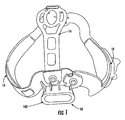
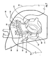
Fig. 1 depicts a head top support system. -
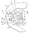
Fig. 2 depicts a headgear support device in accordance with the present invention. -
Fig. 3 shows the headgear support device and a pivot link. -
Fig. 3a shows a rear portion of the pivot link. -
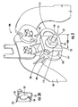
Fig. 4 is a view of the headgear support device and a pivot stop located in a substantially vertical position. -
Fig. 5 is a view of the pivot stop in a substantially horizontal position wherein a peg is received in a lower recess. -
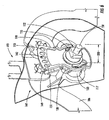
Fig. 6 is a view of a portion of a visor attached to the headgear support device. -
Fig. 7 depicts a knob for tightening or loosening the visor. - Before any embodiments of the invention are explained in detail, it is to be understood that the invention is not limited in its application to the details of construction and the arrangement of components set forth in the following description or illustrated in the following drawings. The invention is capable of other embodiments and of being practiced or of being carried out in various ways. Also, it is to be understood that the phraseology and terminology used herein is for the purpose of description and should not be regarded as limiting. The use of "including," "comprising," or "having" and variations thereof herein is meant to encompass the items listed thereafter and equivalents thereof as well as additional items. Unless specified or limited otherwise, the terms "mounted," "connected," "supported," and "coupled" and variations thereof are used broadly and encompass direct and indirect mountings, connections, supports, and couplings. Further, "connected" and "coupled" are not restricted to physical or mechanical connections or couplings. In the description below, like reference numerals and labels are used to describe the same, similar or corresponding parts in the several views of
Figs. 1-7 . - Referring to
Fig. 1 , a headtop support system 10 is shown which is constructed in three sectional pieces. Thesystem 10 includes anoverhead support band 14, a frontalhead support band 16 and a rearhead support band 18. Theoverhead support band 14 and rearhead support band 18 moves independently relative to the frontalhead support band 16. The three section headgear support is designed to be used with a variety of different types of protective headgear. Representative functional protective structures include welding, brow guard face protection visor, air fed face shield, combinations of these structures, and the like. - The
overhead support band 14 is positioned approximately ninety degrees from the frontalhead support band 16. Theoverhead support band 14, frontalhead support band 16 and rearhead support band 18 are connected at a first and second common connection area. The common connection area allows the three sections to move relative to each other while maintaining restrictions within that movement. Theoverhead support band 14 preferably has an angular range of movement of from about ten degrees or less from the frontalhead support band 16. This range of movement allows proper adjustment of thesystem 10 on the head of the wearer of the protective head covering while permitting balance and comfortable fit of the protective head covering. The rearhead support band 18 has an angular range of movement of from about forty-five degrees or less relative to theoverhead support band 14, allowing therear support band 18 to properly adjust at the base of the back of the user's head. Preferably, both theoverhead support band 14 andrear support band 18 include a length changing mechanism. In the rear support band 18 a ratchet mechanism is preferred and used to ensure that therear support band 18 is inhibited from moving too far up the user's head, regardless of size, which would compromise the reliability of the user to retain the protective head covering during use. Length adjustment of theoverhead support band 14 allows proper fitting of thesystem 10 on multiple users with different head sizes. - Referring to
Fig. 2 , aheadgear support device 100 in accordance with the present invention is shown. Thedevice 100 includes aheadband 106 for accommodating a user's head (only a portion of theheadband 106 is shown). Theheadband 106 includes apivot stud 120 which is located within anelongated slot 103. Thepivot stud 120 is slidable within theslot 103. In accordance with the present invention, translational movement of thepivot stud 120 toward afront end 105 of theslot 103 moves a mask or visor shell either further from a user's face. Conversely, translational movement of thepivot stud 120 towards arear end 107 of theslot 103 moves the visor closer to a user's face. InFig. 2 , the translation movement of thepivot stud 120 is shown byarrow 200 to denote front to back adjustment. Thus, a user may adjust the visor as desired in order to provide greater comfort. In one embodiment, the range of the front to back adjustment is approximately 25 mm. - Top 109 and
bottom 111 portions of aperimeter portion 113 of theslot 103 include a plurality of spaced apart sunken or subsurface portions which serve asadjustment stops 110. The adjustment stops 110 offer guidance to a user regarding a position of a visor or mask shell (collectively referred to as a face shield) relative to the user's face. Thepivot stud 120 further includes around shoulder 115 which rotates relative to aninner surface 117 of theperimeter portion 113 to also enable rotation of thepivot stud 120 relative to theheadband 106. - Referring to
Fig. 3 , theheadgear support device 100 further includes a pivot link 132 (shown in a semi-transparent view) which is located on thepivot stud 120. Referring toFig. 3a , a rear portion of thepivot link 132 is shown. Thepivot link 132 includes ahole 133 which is adapted to mount on theround shoulder 115 of thepivot stud 120. Thepivot link 132 includes upper 135 and lower 137 guide elements which fit over and accommodate thetop 109 andbottom 111 portions of theperimeter portion 113 to thus enable thepivot stud 120 to slide within theslot 103. An internal surface of thepivot link 132 includes raised portions 130 (shown inFig. 3a ) which serve to engage with the sunken or sub surfaces of the adjustment stops 110 to thus locate thepivot stud 120 in theslot 103 relative to theheadband 106. - Referring to
Fig. 4 , theheadgear support device 100 also includes apivot stop 140 located in a substantially vertical position. Thepivot stop 140 is attached to a mask or visor shell of a helmet or other protective headgear. Thepivot stop 140 includes ahole 141 for accommodating theround shoulder 115 of thepivot stud 120 to enable rotation of thepivot stop 140 and thus the mask or visor shell relative to theheadgear 106. Thepivot stop 140 includes upper 143 and lower 145 recesses having a substantially semicircular shape for accommodating astationary location peg 128 which extends from thepivot link 132. InFig. 4 , thepeg 128 is shown located within theupper recess 143 to thus stop rotation of the visor when the face shield is in the down position. - Referring to
Fig. 5 , thepivot stop 140 is shown rotated in a substantially horizontal position wherein the face shield is in the up (raised) position. In this position, thepeg 128 is received in thelower recess 145 to thus stop rotation of the face shield when the face shield is in the up position. Thelower recess 145 further includes an upturned end portion 147 (seeFig. 4 ). Thelower recess 145,upturned end portion 147 and peg 128 are configured to retain thepeg 128 such that face shield is held in the up position. In one embodiment, the design and natural spring of the material used to fabricate the pivot stop 140 create a retaining force on thepeg 128. - Referring to
Fig. 6 , a semi-transparent view of a portion of aface shield 160 is shown attached to theheadgear support device 100. In particular, thevisor 160 includes asquare location hole 155 which receives asquare portion 152 of thepivot stud 120. As previously described, thepivot stud 120 rotates relative to theheadband 106. This causes corresponding rotation of thesquare portion 152 and theface shield 160. Theface shield 160 includes alocation pin 142 which is adapted to engage one of a plurality oflocation slots 149 formed in thepivot stop 140. In particular, positioning of the locatingpin 142 in thelocation slots 149 from afront locating slot 151 to arear locating slot 153 progressively opens theface shield 160 by increasingly larger amounts to provide angular adjustment of theface shield 160 relative to the user's face. - Referring to
Fig. 7 , aknob 170 is secured to a projectingportion 158 of thepivot stud 120. Theknob 170 serves to tighten or loosen theface shield 160 relative to theheadgear support device 100. In operation, a user turns theknob 170 counterclockwise to loosen theheadgear support device 100 to enable translational (front to back) 200 adjustment of theheadgear support device 100 within theslot 103 such that thevisor 160 is positioned a desired distance from the user's face. In addition, the user can rotate thepivot stop 153 andface shield 160 such that the locatingpin 142 is inserted into a desiredlocation slot 149 to provide a desired open or closed position for theface shield 160. The user then turns theknob 170 clockwise to tighten thevisor 160 to fix the location of theheadgear support device 100 within the slot 103 (and thus the front to back adjustment) and the locatingpin 142 in a selectedslot 149.
Claims (9)
- A headgear support device (100) for supporting a face shield comprising:a headband (106) having an elongated slot (103); anda pivot element (120) affixed to the face shield, wherein the pivot element (120) is slidably located within the slot (103) to enable translational movement of the face shield and wherein the pivot element (120) is also rotatable within the slot (103) to enable rotational movement of the face shield; and a pivot link (132); characterised in thatthe pivot link (132) has a hole (133) therein through which the pivot element (120) extends to locate the pivot link (132) on the pivot element (120) and having upper and lower guide elements (135, 137) which fit over and accommodate top and bottom portions (109, 111) of a perimeter (113) of the slot (103) such that the pivot link (132) is constrained for sliding movement relative to the slot with the pivot element (120), a location peg (128) being formed on the pivot link (132); and further includinga pivot stop (140) which, in use, is attached to the face shield, the pivot stop (140) having an hole (141) therein through which the pivot element (120) extends to rotatably mount the pivots top (140) on the pivot element (120), and further having upper and lower recesses (143, 145) into which the location peg (128) is accommodated during rotation of the pivot stop on the pivot element so as to hold the pivot stop in first and second rotational positions on the pivot element corresponding, in use, to raised and lowered positions of the face shield.
- A device according to claim 1, wherein the pivot element (120) includes slots (149) for engaging a locating pin (142) to enable angular adjustment of the face shield relative to a user's face.
- A device according to claim 1, wherein the translational movement enables the face shield to be positioned closer to, or further from, a user's face.
- A device according to claim 1, wherein a perimeter (113) of the slot (103) includes adjustment stops (110) for guiding the user regarding a position of the face shield relative to the user's face.
- A device according to claim 1, wherein the pivot element includes a location peg for stopping rotation of the face shield.
- A device according to claim 1, further including a knob (170) attached to the pivot element (120) for tightening or loosening the headgear support device (100).
- A device according to claim 1, wherein the range of translation motion is approximately 25 mm.
- A device according to any of the preceding claims, wherein the pivot element (120) has a round shoulder (115) on which the pivot link (132) engages.
- A device according to any of the preceding claims, wherein the pivot link (132) includes raised portions (130) on an internal surface of the pivot link (132) which engage with adjustment stops (110) associated with the slot (103) so as to locate the pivot element (120) in the slot (103) relative to the headband (106).
Applications Claiming Priority (2)
| Application Number | Priority Date | Filing Date | Title |
|---|---|---|---|
| US33331510P | 2010-05-11 | 2010-05-11 | |
| PCT/GB2011/050896 WO2011141733A1 (en) | 2010-05-11 | 2011-05-11 | Headgear support device having front-back adjustment |
Publications (2)
| Publication Number | Publication Date |
|---|---|
| EP2568836A1 EP2568836A1 (en) | 2013-03-20 |
| EP2568836B1 true EP2568836B1 (en) | 2014-10-15 |
Family
ID=44120084
Family Applications (1)
| Application Number | Title | Priority Date | Filing Date |
|---|---|---|---|
| EP11722142.4A Not-in-force EP2568836B1 (en) | 2010-05-11 | 2011-05-11 | Headgear support device having front-back adjustment |
Country Status (5)
| Country | Link |
|---|---|
| US (1) | US9427040B2 (en) |
| EP (1) | EP2568836B1 (en) |
| CN (1) | CN103108562B (en) |
| CA (1) | CA2798921C (en) |
| WO (1) | WO2011141733A1 (en) |
Families Citing this family (13)
| Publication number | Priority date | Publication date | Assignee | Title |
|---|---|---|---|---|
| DE102012000820B4 (en) * | 2012-01-17 | 2018-05-30 | Dräger Safety AG & Co. KGaA | Hard hat with a swivel visor |
| US11033433B2 (en) | 2014-06-16 | 2021-06-15 | Illinois Tool Works Inc | Removable shield for protective headwear |
| US9999546B2 (en) | 2014-06-16 | 2018-06-19 | Illinois Tool Works Inc. | Protective headwear with airflow |
| US10016008B2 (en) | 2014-06-16 | 2018-07-10 | Illinois Tool Works Inc. | Headgear for protective headwear |
| CN104071731A (en) * | 2014-06-27 | 2014-10-01 | 苏州柏德纳科技有限公司 | Distribution connector for filling milk |
| US10702003B2 (en) | 2014-12-26 | 2020-07-07 | Illinois Tool Works Inc. | Apparatus for reducing angular velocity of protective shells associated with protective headwear |
| US9737107B2 (en) * | 2015-02-26 | 2017-08-22 | Honeywell International, Inc. | Headgear with a self-adaptive, elastomeric nape belt |
| CN106264862A (en) * | 2015-06-08 | 2017-01-04 | 泰克曼(南京)电子有限公司 | Headband structure and welding mask thereof |
| US9814622B2 (en) | 2015-06-12 | 2017-11-14 | Illinois Tool Works Inc. | Bump cap for face protection members |
| US20160360820A1 (en) | 2015-06-12 | 2016-12-15 | Illinois Tool Works Inc. | Hard Hat Adapter for a Welding Face Member |
| ITUB20154758A1 (en) * | 2015-10-27 | 2017-04-27 | Kask Spa | BAND POGGIA FRONT FOR HELMETS AND HELMET PROVIDED WITH SUCH FRONT POGGIA BAND. |
| USD781502S1 (en) | 2016-05-20 | 2017-03-14 | Illinois Tool Works Inc. | Protective helmet |
| USD779128S1 (en) | 2016-05-20 | 2017-02-14 | Illinois Tool Works Inc. | Protective helmet |
Family Cites Families (27)
| Publication number | Priority date | Publication date | Assignee | Title |
|---|---|---|---|---|
| US1601830A (en) * | 1924-10-09 | 1926-10-05 | Francis D Huntsman | Welder's mask |
| US2283120A (en) * | 1940-12-14 | 1942-05-12 | Chicago Eye Shield Company | Welder's shield |
| US2320244A (en) * | 1940-12-31 | 1943-05-25 | Fibre Metal Products Company | Adjustable headgear connection for helmets |
| US2390006A (en) * | 1942-06-08 | 1945-11-27 | American Optical Corp | Welder's helmet |
| US2788558A (en) * | 1953-03-10 | 1957-04-16 | Fibre Metal Products Company | Detachable connection for mounting a face protector on a head protector |
| US2814043A (en) | 1954-11-16 | 1957-11-26 | Anthony L Alesi | Nape strap |
| US3074072A (en) * | 1959-03-30 | 1963-01-22 | Edwards George Zahnor | Mechanism for mounting a welding shield on headgear |
| US3075201A (en) * | 1960-12-09 | 1963-01-29 | Welsh Mfg Co | Headband assembly for welder's helmet |
| US3430262A (en) * | 1966-09-12 | 1969-03-04 | Bullard Co | Welder's face shield mounting bracket for safety hats |
| US3430263A (en) * | 1967-07-19 | 1969-03-04 | Welsh Mfg Co | Universal stop pin for head protective equipment |
| US3866244A (en) * | 1973-11-08 | 1975-02-18 | Fibre Metal Prod Co | Headgear structure for welding helmets and the like |
| US4124902A (en) * | 1977-10-31 | 1978-11-14 | Mine Safety Appliances Company | Mounting assembly connecting a face shield to a safety hat |
| SE457408B (en) * | 1987-11-02 | 1988-12-27 | Bilsom Ab | MAIN POSITION FOR THE PROTECTION OF PROTECTIVE EQUIPMENT |
| DE4224476C2 (en) * | 1992-07-24 | 1995-10-26 | Optrel Ag | Device for protecting the human head against external influences |
| US5813049A (en) | 1996-12-17 | 1998-09-29 | Xu; Long | Welding helmet |
| US6260197B1 (en) * | 1999-04-09 | 2001-07-17 | Jackson Products, Inc. | Welding helmet with conical pivoting mechanism for head gear strap |
| US6341382B1 (en) | 2000-11-06 | 2002-01-29 | Jackson Products, Inc. | One-piece adjustable headgear support |
| US7007306B2 (en) * | 2003-11-04 | 2006-03-07 | Bacou-Dalloz Eye & Face Protection, Inc. | Face shield assembly |
| KR100643074B1 (en) * | 2004-10-20 | 2006-11-10 | 오토스테크 주식회사 | Multi-functional protective gear mount for hard hat |
| US7865968B2 (en) * | 2006-04-18 | 2011-01-11 | 3M Innovative Properties Company | Head suspension system and headgear that have an adjustable visor and method of adjusting same |
| US8161576B2 (en) * | 2007-02-01 | 2012-04-24 | Sellstrom Manufacturing Company | Protective headgear assembly |
| RU2414830C1 (en) * | 2007-10-10 | 2011-03-27 | 3М Инновейтив Пропертиз Компани | Head suspension with transient links and back support |
| US20100212058A1 (en) * | 2009-02-25 | 2010-08-26 | Lincoln Global, Inc. | Tiltable welding helmet |
| CH700540A2 (en) * | 2009-03-02 | 2010-09-15 | Sperian Welding Prot Ag | Adapter system and adapter for mask. |
| US20110302701A1 (en) * | 2010-06-09 | 2011-12-15 | Kin Yung Lung Industrial Co., Ltd. | Position controlling mechanism for chin guard and visor plate of helmet |
| KR101253075B1 (en) * | 2010-12-13 | 2013-04-10 | 주식회사 오토스윙 | Head band |
| KR101236728B1 (en) * | 2010-12-13 | 2013-02-25 | 주식회사 오토스윙 | A hinge structure |
-
2011
- 2011-05-11 CA CA2798921A patent/CA2798921C/en not_active Expired - Fee Related
- 2011-05-11 WO PCT/GB2011/050896 patent/WO2011141733A1/en not_active Ceased
- 2011-05-11 CN CN201180023821.1A patent/CN103108562B/en not_active Expired - Fee Related
- 2011-05-11 EP EP11722142.4A patent/EP2568836B1/en not_active Not-in-force
- 2011-05-11 US US13/697,307 patent/US9427040B2/en not_active Expired - Fee Related
Also Published As
| Publication number | Publication date |
|---|---|
| EP2568836A1 (en) | 2013-03-20 |
| WO2011141733A1 (en) | 2011-11-17 |
| US20130205474A1 (en) | 2013-08-15 |
| CA2798921A1 (en) | 2011-11-17 |
| CN103108562B (en) | 2016-01-27 |
| CN103108562A (en) | 2013-05-15 |
| CA2798921C (en) | 2019-01-15 |
| US9427040B2 (en) | 2016-08-30 |
Similar Documents
| Publication | Publication Date | Title |
|---|---|---|
| US9427040B2 (en) | Headgear support device having front-back adjustment | |
| US20200196698A1 (en) | Pivot-Arm Assembly for a Helmet Mounted Headset | |
| US11375766B2 (en) | Adjustable helmet for a hockey or lacrosse player | |
| EP3071061B1 (en) | Mandible guard adjustment system | |
| KR101878275B1 (en) | Visor attachment mechanism in helmet | |
| US7430763B1 (en) | Visor mounted face protector | |
| ES2989937T3 (en) | Visor carrier assembly | |
| EP2348906B1 (en) | Headband with pivotal pad | |
| US6598238B2 (en) | Jaw protecting apparatus of helmet | |
| US8434168B2 (en) | Weight balancing face shield | |
| CN115915990A (en) | Hard hat with lacing system | |
| US8321962B2 (en) | Adapter system for coupling a protective mask to a helmet | |
| CN104093332B (en) | Protect the helmet and screen | |
| US20140173811A1 (en) | Unit composed of helmet and protective eye mask | |
| BR112013000582B1 (en) | EAR PROTECTION TO BE FIXED TO A PROTECTION HELMET, PARTICULARLY FOR FOREST ENGINEERS | |
| JP2009544858A (en) | Protective helmet, especially bicycle helmet | |
| WO2015123280A1 (en) | Appliance mounting device and system for head gear | |
| ITUB20154758A1 (en) | BAND POGGIA FRONT FOR HELMETS AND HELMET PROVIDED WITH SUCH FRONT POGGIA BAND. | |
| ES2375538T3 (en) | HELMET WITH AN EYE PROTECTION. | |
| GB2558317A (en) | Ergonomic occipital triangular cushion pad for head bands | |
| CN111417325A (en) | Motorcycle rider protective helmet with sun shield | |
| KR200479141Y1 (en) | Safety helmet | |
| AU2011101018A4 (en) | Helmet Brim | |
| US20170224040A1 (en) | Cap having folding visor | |
| US20140217137A1 (en) | Gun Holder |
Legal Events
| Date | Code | Title | Description |
|---|---|---|---|
| PUAI | Public reference made under article 153(3) epc to a published international application that has entered the european phase |
Free format text: ORIGINAL CODE: 0009012 |
|
| 17P | Request for examination filed |
Effective date: 20121114 |
|
| AK | Designated contracting states |
Kind code of ref document: A1 Designated state(s): AL AT BE BG CH CY CZ DE DK EE ES FI FR GB GR HR HU IE IS IT LI LT LU LV MC MK MT NL NO PL PT RO RS SE SI SK SM TR |
|
| DAX | Request for extension of the european patent (deleted) | ||
| 17Q | First examination report despatched |
Effective date: 20130910 |
|
| GRAP | Despatch of communication of intention to grant a patent |
Free format text: ORIGINAL CODE: EPIDOSNIGR1 |
|
| INTG | Intention to grant announced |
Effective date: 20140314 |
|
| RIN1 | Information on inventor provided before grant (corrected) |
Inventor name: HALL, CHRISTOPHER Inventor name: LEYLAND, SALLY |
|
| GRAS | Grant fee paid |
Free format text: ORIGINAL CODE: EPIDOSNIGR3 |
|
| GRAA | (expected) grant |
Free format text: ORIGINAL CODE: 0009210 |
|
| AK | Designated contracting states |
Kind code of ref document: B1 Designated state(s): AL AT BE BG CH CY CZ DE DK EE ES FI FR GB GR HR HU IE IS IT LI LT LU LV MC MK MT NL NO PL PT RO RS SE SI SK SM TR |
|
| REG | Reference to a national code |
Ref country code: CH Ref legal event code: EP Ref country code: GB Ref legal event code: FG4D |
|
| REG | Reference to a national code |
Ref country code: IE Ref legal event code: FG4D |
|
| REG | Reference to a national code |
Ref country code: AT Ref legal event code: REF Ref document number: 691231 Country of ref document: AT Kind code of ref document: T Effective date: 20141115 |
|
| REG | Reference to a national code |
Ref country code: DE Ref legal event code: R096 Ref document number: 602011010622 Country of ref document: DE Effective date: 20141127 |
|
| REG | Reference to a national code |
Ref country code: NL Ref legal event code: VDEP Effective date: 20141015 |
|
| REG | Reference to a national code |
Ref country code: AT Ref legal event code: MK05 Ref document number: 691231 Country of ref document: AT Kind code of ref document: T Effective date: 20141015 |
|
| REG | Reference to a national code |
Ref country code: LT Ref legal event code: MG4D |
|
| PG25 | Lapsed in a contracting state [announced via postgrant information from national office to epo] |
Ref country code: NL Free format text: LAPSE BECAUSE OF FAILURE TO SUBMIT A TRANSLATION OF THE DESCRIPTION OR TO PAY THE FEE WITHIN THE PRESCRIBED TIME-LIMIT Effective date: 20141015 |
|
| PG25 | Lapsed in a contracting state [announced via postgrant information from national office to epo] |
Ref country code: FI Free format text: LAPSE BECAUSE OF FAILURE TO SUBMIT A TRANSLATION OF THE DESCRIPTION OR TO PAY THE FEE WITHIN THE PRESCRIBED TIME-LIMIT Effective date: 20141015 Ref country code: LT Free format text: LAPSE BECAUSE OF FAILURE TO SUBMIT A TRANSLATION OF THE DESCRIPTION OR TO PAY THE FEE WITHIN THE PRESCRIBED TIME-LIMIT Effective date: 20141015 Ref country code: PT Free format text: LAPSE BECAUSE OF FAILURE TO SUBMIT A TRANSLATION OF THE DESCRIPTION OR TO PAY THE FEE WITHIN THE PRESCRIBED TIME-LIMIT Effective date: 20150216 Ref country code: ES Free format text: LAPSE BECAUSE OF FAILURE TO SUBMIT A TRANSLATION OF THE DESCRIPTION OR TO PAY THE FEE WITHIN THE PRESCRIBED TIME-LIMIT Effective date: 20141015 Ref country code: NO Free format text: LAPSE BECAUSE OF FAILURE TO SUBMIT A TRANSLATION OF THE DESCRIPTION OR TO PAY THE FEE WITHIN THE PRESCRIBED TIME-LIMIT Effective date: 20150115 Ref country code: IS Free format text: LAPSE BECAUSE OF FAILURE TO SUBMIT A TRANSLATION OF THE DESCRIPTION OR TO PAY THE FEE WITHIN THE PRESCRIBED TIME-LIMIT Effective date: 20150215 |
|
| PG25 | Lapsed in a contracting state [announced via postgrant information from national office to epo] |
Ref country code: CY Free format text: LAPSE BECAUSE OF FAILURE TO SUBMIT A TRANSLATION OF THE DESCRIPTION OR TO PAY THE FEE WITHIN THE PRESCRIBED TIME-LIMIT Effective date: 20141015 Ref country code: RS Free format text: LAPSE BECAUSE OF FAILURE TO SUBMIT A TRANSLATION OF THE DESCRIPTION OR TO PAY THE FEE WITHIN THE PRESCRIBED TIME-LIMIT Effective date: 20141015 Ref country code: GR Free format text: LAPSE BECAUSE OF FAILURE TO SUBMIT A TRANSLATION OF THE DESCRIPTION OR TO PAY THE FEE WITHIN THE PRESCRIBED TIME-LIMIT Effective date: 20150116 Ref country code: LV Free format text: LAPSE BECAUSE OF FAILURE TO SUBMIT A TRANSLATION OF THE DESCRIPTION OR TO PAY THE FEE WITHIN THE PRESCRIBED TIME-LIMIT Effective date: 20141015 Ref country code: PL Free format text: LAPSE BECAUSE OF FAILURE TO SUBMIT A TRANSLATION OF THE DESCRIPTION OR TO PAY THE FEE WITHIN THE PRESCRIBED TIME-LIMIT Effective date: 20141015 Ref country code: AT Free format text: LAPSE BECAUSE OF FAILURE TO SUBMIT A TRANSLATION OF THE DESCRIPTION OR TO PAY THE FEE WITHIN THE PRESCRIBED TIME-LIMIT Effective date: 20141015 Ref country code: HR Free format text: LAPSE BECAUSE OF FAILURE TO SUBMIT A TRANSLATION OF THE DESCRIPTION OR TO PAY THE FEE WITHIN THE PRESCRIBED TIME-LIMIT Effective date: 20141015 Ref country code: SE Free format text: LAPSE BECAUSE OF FAILURE TO SUBMIT A TRANSLATION OF THE DESCRIPTION OR TO PAY THE FEE WITHIN THE PRESCRIBED TIME-LIMIT Effective date: 20141015 |
|
| REG | Reference to a national code |
Ref country code: DE Ref legal event code: R097 Ref document number: 602011010622 Country of ref document: DE |
|
| PG25 | Lapsed in a contracting state [announced via postgrant information from national office to epo] |
Ref country code: CZ Free format text: LAPSE BECAUSE OF FAILURE TO SUBMIT A TRANSLATION OF THE DESCRIPTION OR TO PAY THE FEE WITHIN THE PRESCRIBED TIME-LIMIT Effective date: 20141015 Ref country code: RO Free format text: LAPSE BECAUSE OF FAILURE TO SUBMIT A TRANSLATION OF THE DESCRIPTION OR TO PAY THE FEE WITHIN THE PRESCRIBED TIME-LIMIT Effective date: 20141015 Ref country code: SK Free format text: LAPSE BECAUSE OF FAILURE TO SUBMIT A TRANSLATION OF THE DESCRIPTION OR TO PAY THE FEE WITHIN THE PRESCRIBED TIME-LIMIT Effective date: 20141015 Ref country code: DK Free format text: LAPSE BECAUSE OF FAILURE TO SUBMIT A TRANSLATION OF THE DESCRIPTION OR TO PAY THE FEE WITHIN THE PRESCRIBED TIME-LIMIT Effective date: 20141015 Ref country code: EE Free format text: LAPSE BECAUSE OF FAILURE TO SUBMIT A TRANSLATION OF THE DESCRIPTION OR TO PAY THE FEE WITHIN THE PRESCRIBED TIME-LIMIT Effective date: 20141015 |
|
| PLBE | No opposition filed within time limit |
Free format text: ORIGINAL CODE: 0009261 |
|
| STAA | Information on the status of an ep patent application or granted ep patent |
Free format text: STATUS: NO OPPOSITION FILED WITHIN TIME LIMIT |
|
| PG25 | Lapsed in a contracting state [announced via postgrant information from national office to epo] |
Ref country code: IT Free format text: LAPSE BECAUSE OF FAILURE TO SUBMIT A TRANSLATION OF THE DESCRIPTION OR TO PAY THE FEE WITHIN THE PRESCRIBED TIME-LIMIT Effective date: 20141015 |
|
| 26N | No opposition filed |
Effective date: 20150716 |
|
| REG | Reference to a national code |
Ref country code: CH Ref legal event code: PL |
|
| PG25 | Lapsed in a contracting state [announced via postgrant information from national office to epo] |
Ref country code: LU Free format text: LAPSE BECAUSE OF FAILURE TO SUBMIT A TRANSLATION OF THE DESCRIPTION OR TO PAY THE FEE WITHIN THE PRESCRIBED TIME-LIMIT Effective date: 20150511 Ref country code: LI Free format text: LAPSE BECAUSE OF NON-PAYMENT OF DUE FEES Effective date: 20150531 Ref country code: MC Free format text: LAPSE BECAUSE OF FAILURE TO SUBMIT A TRANSLATION OF THE DESCRIPTION OR TO PAY THE FEE WITHIN THE PRESCRIBED TIME-LIMIT Effective date: 20141015 Ref country code: CH Free format text: LAPSE BECAUSE OF NON-PAYMENT OF DUE FEES Effective date: 20150531 |
|
| REG | Reference to a national code |
Ref country code: IE Ref legal event code: MM4A |
|
| PG25 | Lapsed in a contracting state [announced via postgrant information from national office to epo] |
Ref country code: SI Free format text: LAPSE BECAUSE OF FAILURE TO SUBMIT A TRANSLATION OF THE DESCRIPTION OR TO PAY THE FEE WITHIN THE PRESCRIBED TIME-LIMIT Effective date: 20141015 |
|
| PG25 | Lapsed in a contracting state [announced via postgrant information from national office to epo] |
Ref country code: IE Free format text: LAPSE BECAUSE OF NON-PAYMENT OF DUE FEES Effective date: 20150511 |
|
| REG | Reference to a national code |
Ref country code: FR Ref legal event code: PLFP Year of fee payment: 6 |
|
| PG25 | Lapsed in a contracting state [announced via postgrant information from national office to epo] |
Ref country code: MT Free format text: LAPSE BECAUSE OF FAILURE TO SUBMIT A TRANSLATION OF THE DESCRIPTION OR TO PAY THE FEE WITHIN THE PRESCRIBED TIME-LIMIT Effective date: 20141015 |
|
| REG | Reference to a national code |
Ref country code: FR Ref legal event code: PLFP Year of fee payment: 7 |
|
| PG25 | Lapsed in a contracting state [announced via postgrant information from national office to epo] |
Ref country code: BG Free format text: LAPSE BECAUSE OF FAILURE TO SUBMIT A TRANSLATION OF THE DESCRIPTION OR TO PAY THE FEE WITHIN THE PRESCRIBED TIME-LIMIT Effective date: 20141015 Ref country code: SM Free format text: LAPSE BECAUSE OF FAILURE TO SUBMIT A TRANSLATION OF THE DESCRIPTION OR TO PAY THE FEE WITHIN THE PRESCRIBED TIME-LIMIT Effective date: 20141015 Ref country code: HU Free format text: LAPSE BECAUSE OF FAILURE TO SUBMIT A TRANSLATION OF THE DESCRIPTION OR TO PAY THE FEE WITHIN THE PRESCRIBED TIME-LIMIT; INVALID AB INITIO Effective date: 20110511 |
|
| PG25 | Lapsed in a contracting state [announced via postgrant information from national office to epo] |
Ref country code: TR Free format text: LAPSE BECAUSE OF FAILURE TO SUBMIT A TRANSLATION OF THE DESCRIPTION OR TO PAY THE FEE WITHIN THE PRESCRIBED TIME-LIMIT Effective date: 20141015 |
|
| PG25 | Lapsed in a contracting state [announced via postgrant information from national office to epo] |
Ref country code: BE Free format text: LAPSE BECAUSE OF FAILURE TO SUBMIT A TRANSLATION OF THE DESCRIPTION OR TO PAY THE FEE WITHIN THE PRESCRIBED TIME-LIMIT Effective date: 20141015 |
|
| REG | Reference to a national code |
Ref country code: FR Ref legal event code: PLFP Year of fee payment: 8 |
|
| PGFP | Annual fee paid to national office [announced via postgrant information from national office to epo] |
Ref country code: GB Payment date: 20180329 Year of fee payment: 8 |
|
| PG25 | Lapsed in a contracting state [announced via postgrant information from national office to epo] |
Ref country code: MK Free format text: LAPSE BECAUSE OF FAILURE TO SUBMIT A TRANSLATION OF THE DESCRIPTION OR TO PAY THE FEE WITHIN THE PRESCRIBED TIME-LIMIT Effective date: 20141015 |
|
| PGFP | Annual fee paid to national office [announced via postgrant information from national office to epo] |
Ref country code: DE Payment date: 20180502 Year of fee payment: 8 |
|
| PGFP | Annual fee paid to national office [announced via postgrant information from national office to epo] |
Ref country code: FR Payment date: 20180411 Year of fee payment: 8 |
|
| PG25 | Lapsed in a contracting state [announced via postgrant information from national office to epo] |
Ref country code: AL Free format text: LAPSE BECAUSE OF FAILURE TO SUBMIT A TRANSLATION OF THE DESCRIPTION OR TO PAY THE FEE WITHIN THE PRESCRIBED TIME-LIMIT Effective date: 20141015 |
|
| REG | Reference to a national code |
Ref country code: DE Ref legal event code: R119 Ref document number: 602011010622 Country of ref document: DE |
|
| GBPC | Gb: european patent ceased through non-payment of renewal fee |
Effective date: 20190511 |
|
| PG25 | Lapsed in a contracting state [announced via postgrant information from national office to epo] |
Ref country code: DE Free format text: LAPSE BECAUSE OF NON-PAYMENT OF DUE FEES Effective date: 20191203 Ref country code: GB Free format text: LAPSE BECAUSE OF NON-PAYMENT OF DUE FEES Effective date: 20190511 |
|
| PG25 | Lapsed in a contracting state [announced via postgrant information from national office to epo] |
Ref country code: FR Free format text: LAPSE BECAUSE OF NON-PAYMENT OF DUE FEES Effective date: 20190531 |