EP2568555A1 - Ligne de transport de courant comportant des moyens de guidage de l'extremite du conducteur interne - Google Patents
Ligne de transport de courant comportant des moyens de guidage de l'extremite du conducteur interne Download PDFInfo
- Publication number
- EP2568555A1 EP2568555A1 EP12183696A EP12183696A EP2568555A1 EP 2568555 A1 EP2568555 A1 EP 2568555A1 EP 12183696 A EP12183696 A EP 12183696A EP 12183696 A EP12183696 A EP 12183696A EP 2568555 A1 EP2568555 A1 EP 2568555A1
- Authority
- EP
- European Patent Office
- Prior art keywords
- conductor
- connecting member
- transmission line
- power transmission
- line according
- Prior art date
- Legal status (The legal status is an assumption and is not a legal conclusion. Google has not performed a legal analysis and makes no representation as to the accuracy of the status listed.)
- Granted
Links
Images
Classifications
-
- H—ELECTRICITY
- H02—GENERATION; CONVERSION OR DISTRIBUTION OF ELECTRIC POWER
- H02G—INSTALLATION OF ELECTRIC CABLES OR LINES, OR OF COMBINED OPTICAL AND ELECTRIC CABLES OR LINES
- H02G5/00—Installations of bus-bars
- H02G5/06—Totally-enclosed installations, e.g. in metal casings
- H02G5/066—Devices for maintaining distance between conductor and enclosure
- H02G5/068—Devices for maintaining distance between conductor and enclosure being part of the junction between two enclosures
-
- H—ELECTRICITY
- H02—GENERATION; CONVERSION OR DISTRIBUTION OF ELECTRIC POWER
- H02G—INSTALLATION OF ELECTRIC CABLES OR LINES, OR OF COMBINED OPTICAL AND ELECTRIC CABLES OR LINES
- H02G5/00—Installations of bus-bars
- H02G5/06—Totally-enclosed installations, e.g. in metal casings
- H02G5/061—Tubular casings
Definitions
- the invention relates to an electric power transmission line comprising a support member designed to allow a relative axial displacement of the end of an inner conductor of the line relative to the associated end of an outer envelope. of the line.
- a power transmission line consists of a plurality of sections that are connected end to end and each of which measures for example a hundred meters in length.
- Each section mainly comprises a cylindrical outer envelope and an inner cylindrical conductor concentric with the envelope.
- Insulating supports make it possible to keep the conductor away from the casing, thus avoiding short circuits between the conductor and the casing, which are put at different electrical potentials.
- a connecting member is arranged at at least one end of a section, for the electrical connection of said section to another section, and also to support the end of the conductor.
- the transmission line is arranged outside, so it is subject to external thermal variations. In addition, when it is crossed by an electric current, the driver is allowed to heat up.
- the conductor and the envelope are likely to expand, differently from one another.
- the differences in expansion between the conductor and the envelope can be characterized by a relative difference in the length of the conductor relative to the length of the envelope up to 350 mm.
- the conductor is movably mounted in the envelope so as to allow the relative length variations between the conductor and the envelope.
- each section of the transport line comprises, at at least one of its ends, a connecting member which guides the associated end of the conductor relative to the end of the envelope during their dimensional variations and which also realizes the electrical connection of the conductor to a component mounted at the end of the section of the line.
- the connecting member comprises a cylindrical axis which is received in the end of the conductor and at least one electrical contact, for example an annular spring. which is compressed radially between the axis and the end of the conductor, so as to allow an electrical connection between the conductor and the connecting member.
- the shaft supports the weight of the driver, which is about 35 kg for a length of 9 m and it allows a longitudinal displacement of the end of the conductor relative to the connecting member.
- the stroke of the end of the conductor is about 10 mm in each direction.
- this embodiment is not suitable for a longer length section, as defined above, for which the stroke of the end of the conductor is about 350 mm.
- the friction between the end of the conductor and the contact can produce a significant wear of the contact and / or the end of the conductor, thus limiting the overall life of the installation.
- the purpose of the invention is to propose a transmission line in which the connection between the connecting member and the end of the conductor allows a greater stroke of the end of the conductor, while limiting the phenomenon of wear produced by this displacement.
- the invention proposes an electric power transmission line comprising an envelope external cylindrical main longitudinal axis, a cylindrical conductor of main axis A substantially parallel to the longitudinal axis of the casing, which is arranged inside the casing, and a connecting member of one end longitudinal longitudinal front of the conductor at a longitudinal end front of the outer casing which is designed to guide the leading end of the conductor moving in the front end of the casing at least in the longitudinal direction, the connecting member having a body which is fixed to the front end of the casing and having a guide arm of the leading end of the conductor which extends longitudinally rearwardly from the body and whose free rear end is received at the inside of the front end of the conductor to cooperate with an inner cylindrical surface of the front end of the conductor, characterized in that the rear end of the arm at least one linear guide member which is rotatably mounted relative to the rear end of the arm about at least one transverse axis and in that the leading end of the conductor rests vertically downwardly on said guidance at its inner cylindrical surface.
- the rolling contact between the support member and the end of the conductor makes it possible to support the conductor mass and to significantly reduce the friction between the connecting member and the conductor, thus limiting the wear of these components.
- the guide element consists of a wheel mounted free to rotate relative to the connecting member about a transverse axis which supports the front end of the conductor.
- the diameter of the wheel is smaller than the inside diameter of the front end of the conductor and the transverse axis of rotation of the wheel is located vertically above the longitudinal axis of the front end of the conductor.
- the connecting member is electrically connected with the conductor.
- the connecting member comprises metal blades, one end of each blade is in sliding contact on the outer cylindrical surface of the conductor.
- each blade bears elastically on the outer cylindrical surface of the conductor.
- the blades are carried by a cylindrical sleeve which extends longitudinally rearwardly from the body of the connecting member and whose inner diameter of the sleeve is greater than the diameter of the leading end of the conductor.
- the connecting member comprises a plurality of blades distributed around the periphery of the free rear longitudinal end of the sleeve and each blade extends longitudinally rearward and radially inwardly of the sleeve, from the rear end of the sleeve.
- the connecting member comprises an annular cover which is mounted on the rear end of the sleeve and which covers longitudinally and radially the blades.
- the body of the connecting member is fixed to the casing by means of an electrically insulating support having a metal central element to which the body of the connecting member is fixed.
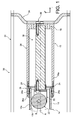
- figure 1 a front end of a section 30 of a medium, high or very high voltage electric power transmission line.
- the section 30 of the transmission line comprises mainly an outer cylindrical casing 32 of longitudinal main axis and a current conductor 14 of principal axis A substantially parallel to the longitudinal axis of the outer casing 32.
- the outer casing 32 and the conductor 14 are made of electrically conductive material, for example aluminum, and are brought to different electrical potentials.
- the outer casing 32 delimits a cylindrical volume which is closed and which is filled with an insulating gas under pressure limiting the risk of short circuit with the conductor 14.
- a connecting member 10 connects an end of the outer casing 32 of the section 30, here the front end of the outer casing 32, with a front end 12 of the current conductor 14.
- the section 30 of the transmission line is installed outdoors, so it is subject to external climatic conditions. Consequently, depending on the climatic conditions, the conductor 14 and the envelope 32 expand, each in different amplitudes. Also, when it is crossed by an electric current, the conductor 14 expands.
- the axial length of the conductor 14 varies with respect to the axial length of the casing 32, which causes the front end 12 of the conductor 14 to move longitudinally with respect to the front end of the casing 32.
- the function of the connecting member 10 is to guide the front end 12 of the conductor 14 in longitudinal displacement with respect to the front end of the envelope 32, while supporting the weight of the conductor 14.
- the connecting member 10 is electrically connected to the conductor 14 to allow the electrical connection of the front end of the section 30.
- the connecting member 10 is fixed to the front end of the envelope 32 via an insulating support 34 which is generally in the form of a coaxial element to the envelope 32, which is gas-tight contained in the casing 32 and a metal central element 36 to which the connecting member 10 is fixed.
- the connecting member 10 comprises a body 16 which extends in a plane transverse to the longitudinal main axis A of the conductor 14.
- the body 16 is attached to the central element 36 of the insulating support 34 so that the connecting member 10 is electrically connected to the central element 36.
- the connecting member 10 comprises an arm 18 for guiding the front end 12 of the conductor 14, which generally consists of a longitudinal bar, which extends longitudinally rearwards from the body 16 and which is generally coaxial with the main axis A of the driver 14.
- the free rear end 20 of the arm 18 is received inside the front end 12 of the conductor 14 and it cooperates with the inner surface 12i of the front end 12 of the conductor 14 to carry out the longitudinal displacement guide and the vertically supporting the driver 14.
- the radial dimensions of the arm 18 with respect to the longitudinal axis A are smaller than the internal diameter of the front end 12 of the conductor 14.
- the connecting member 10 also comprises a wheel 22 which is mounted free to rotate relative to the rear end 20 of the arm 18 about a transverse axis B.
- the wheel 22 is supported upwards against the inner surface 12i of the front end 12 of the conductor 14.
- the outer diameter of the wheel 22 is smaller than the inside diameter of the front end 12 of the conductor 14 and the axis B of rotation of the wheel 22 is situated vertically above the principal axis A of the conductor 14.
- the front end 12 of the conductor 14 rests vertically downwardly on the wheel 22, the contact of the wheel 22 with the inner surface 12i of the front end 12 of the conductor 14 is located in the upper part of the end. before driver 12 14.
- the wheel 22 is centered transversely to the main axis of the conductor 14 and the connecting member 10.
- the forces produced by the front end 12 of the conductor 14 are oriented in the median main plane of the wheel 22.
- the orientation of the axis B of rotation of the wheel 22 serves to guide the front end 12 of the conductor 14 along the longitudinal direction L.
- the connecting member 10 is designed to allow a large range of displacement of the front end 12 of the conductor 14 in the longitudinal direction.
- the connecting member 10 is made to allow a longitudinal displacement of about 350 mm from the front end 12 of the conductor 14 relative to the front end of the envelope, that is to say that the stroke of the front end 12 of the conductor 14 relative to the connecting member 10 is about 350 mm.
- the length of the arm 18 is defined so that the distance between the axis B of rotation of the wheel 22 and the body 16 of the connecting member 10 is greater than the stroke of 350 mm from the end before 12 of the conductor 14 with respect to the connecting member 10.
- the connecting member 10 is electrically connected to the connector 14, to allow the electrical connection of the section 30 with an electrical component arranged in front of the section 30, for example with another similar section of the transmission line.
- the connecting member 10 is made of an electrically conductive material, for example aluminum, and it comprises a plurality of conductive blades 24 which are in contact with the outer cylindrical surface 12 of the front end 12 of the conductor 14 .
- the blades 24 are carried by a cylindrical sleeve 26 which is generally coaxial with the arm 18 and extends longitudinally rearwardly from the body 16.
- the blades 24 are arranged at the free rear end of the sleeve 26, and they are distributed around the periphery of the rear end 26a of the sleeve 26.
- the number of blades 24 is relatively large, to reduce the electrical resistance of the connection between the conductor 14 and the connecting member.
- each blade 24 extends generally longitudinally rearwards from the rear end 26a of the sleeve 26 and is bent radially inward along the longitudinal main axis of the sleeve 26.
- each blade 24 is thus closer radially to the main axis A of the sleeve 26 than the front end of the blade 24.
- each blade 24 is made so that in the rest position, that is to say in the absence of the conductor 14, the rear end 24a of each blade 24 is located at a radial dimension less than the radius of the surface external conductor 12e 14. Thus, in the presence of the conductor 14, each blade 24 is elastically deformed and exerts an elastic pressure force from its rear end 24a on the outer surface 12e of the conductor 14.
- this elastic force is reinforced if necessary by an annular spring (not shown) which is arranged on the periphery of the blades 24.
- the internal diameter of the sleeve 26 is greater than the external diameter of the conductor 14.
- the radial clearance between the sleeve 26 and the conductor 14 allows the front end 12 of the conductor 14 to move inside the sleeve 26, and also allows a radial expansion of the front end 12 of the conductor 14.
- the arm 18 and the wheel 22 support the weight of the conductor 14.
- the arm 18 deforms elastically by bending downwards.
- the radial clearance between the sleeve 26 and the conductor 14 is defined to allow a vertical downward movement of the front end 12 of the conductor 14 due to this elastic deformation of the arm 18, and more generally to allow a lack of coaxiality between the sleeve 26 and the conductor 14.
- blades 24 are made of elastically deformable material, they remain in contact on the outer face 12e of the front end 12 of the conductor, regardless of the position of the main axis A of the conductor 14 relative to the body of the link 10, and also whatever the level of radial expansion of the conductor 14.
- the connecting member 10 comprises an annular cover 28 which is mounted on the rear end 26a of the sleeve 26 so as to extend the sleeve 26 towards the rear, and which radially covers the blades 24.
- the annular cover 28 makes it possible to fix the blades 24 to the sleeve 26 by crimping to obtain a dielectrically acceptable assembly
- the free rear end 28a of the cover 28 is located axially behind the rear ends 24a of the blades 24 and is tightened radially to be closer to the outer surface 12e of the front end 12 of the conductor 14.
- the cover 28 thus forms an annular receptacle located below the rear ends of the blades 24.
- the free rear end 28a of the cover 28 also carries an annular seal of the wiper type (not shown), which is compressed between the rear end 28a of the cover 28 and the outer cylindrical surface 12e of the front end 12 of the conductor 14 to prevent particles from coming out of the cover 28.
- the invention is not limited to this single embodiment in which the connecting member 10 comprises a wheel 22 for supporting and guiding the front end 12 of the conductor 14 and that the invention relates to any component able to roll on the inner surface of the driver.
- the connecting member 10 comprises a ball which is carried by the free end 20 of the arm, and which is free to rotate relative to the free end of the arm 18.
- the connecting member 10 comprises a plurality of wheels 22 aligned longitudinally, which limits the forces experienced by each wheel 22 and increase their service life.
- the invention is not limited to this single embodiment in which the electrical connection between the connecting member 10 and the conductor 12 comprises a plurality of conductive blades 24 which are in contact with the surface.
- external cylindrical 12e of the front end 12 of the conductor 14 and that the invention relates to any connecting member comprising means capable of making an electrical connection such as for example spring contacts or contact pins assembled by spring.
- the rear end 20 and the arm 18 are made in one piece.
Landscapes
- Installation Of Bus-Bars (AREA)
- Current-Collector Devices For Electrically Propelled Vehicles (AREA)
Abstract
Description
- L'invention concerne une ligne de transport de courant électrique qui comporte un organe de support réalisé de manière à permettre un déplacement axial relatif de l'extrémité d'un conducteur interne de la ligne par rapport à l'extrémité associée d'une enveloppe externe de la ligne.
- Une ligne de transport de courant est constituée d'une pluralité de tronçons qui sont raccordés bout à bout et dont chacun mesure par exemple une centaine de mètres de longueur. Chaque tronçon comporte principalement une enveloppe externe cylindrique et un conducteur interne cylindrique concentrique avec l'enveloppe.
- Des supports isolants permettent de maintenir le conducteur à distance de l'enveloppe, évitant ainsi les court-circuits entre le conducteur et l'enveloppe, qui sont mis à des potentiels électriques différents.
- Un organe de liaison est agencé à au moins l'une des extrémités d'un tronçon, pour le raccordement électrique dudit tronçon à un autre tronçon, et aussi pour supporter l'extrémité du conducteur.
- La ligne de transport est agencée à l'extérieur, elle est donc soumise aux variations thermiques externes. De plus, lorsqu'il est traversé par un courant électrique, le conducteur est amené à s'échauffer.
- Ainsi, le conducteur et l'enveloppe sont susceptibles de se dilater, de manière différente l'un par rapport à l'autre.
- A titre d'exemple, pour un tronçon d'une ligne de transport qui mesure environ cent mètres de longueur, les différences de dilatations entre le conducteur et l'enveloppe peuvent se caractériser par un écart relatif de la longueur du conducteur par rapport à la longueur de l'enveloppe pouvant atteindre jusqu'à 350 mm.
- Le conducteur est monté mobile dans l'enveloppe de manière à permettre les variations relatives de longueur entre le conducteur et l'enveloppe.
- Ainsi, chaque tronçon de la ligne de transport comporte, à au moins une de ses extrémités, un organe de liaison qui réalise le guidage de l'extrémité associée du conducteur par rapport à l'extrémité de l'enveloppe lors de leurs variations dimensionnelles et qui réalise aussi le raccordement électrique du conducteur à un composant monté à l'extrémité du tronçon de la ligne.
- Selon un mode de réalisation connu, l'organe de liaison comporte un axe cylindrique qui est reçu dans l'extrémité du conducteur et au moins un contact électrique, par exemple un ressort annulaire qui est comprimé radialement entre l'axe et l'extrémité du conducteur, de manière à permettre un raccordement électrique entre le conducteur et l'organe de liaison.
- L'axe supporte le poids du conducteur, qui est d'environ 35 kg pour une longueur de 9 m et il permet un déplacement longitudinal de l'extrémité du conducteur par rapport à l'organe de liaison.
- Selon ce mode de réalisation, la course de l'extrémité du conducteur est de 10 mm environ dans chaque sens.
- Ainsi, ce mode de réalisation n'est pas adapté pour un tronçon de longueur plus importante, tel que défini ci-dessus, pour lequel la course de l'extrémité du conducteur est d'environ 350 mm.
- Aussi, à cause du poids important du conducteur (compris entre 35kg et 60kg selon le type de conducteur et sa longueur) qui pèse sur le contact électrique, le frottement entre l'extrémité du conducteur et le contact peut produire une usure importante du contact et/ou de l'extrémité du conducteur, limitant ainsi la durée de vie globale de l'installation.
- L'invention a pour but de proposer une ligne de transport dans laquelle le raccordement entre l'organe de liaison et l'extrémité du conducteur permet une course plus importante de l'extrémité du conducteur, tout en limitant le phénomène d'usure produite par ce déplacement.
- L'invention propose une ligne de transport de courant électrique comportant une enveloppe cylindrique externe d'axe principal longitudinal, un conducteur cylindrique d'axe principal A longitudinal sensiblement parallèle à l'axe principal de l'enveloppe, qui est agencé à l'intérieur de l'enveloppe, et un organe de liaison d'une extrémité longitudinale avant du conducteur à une extrémité longitudinale avant de l'enveloppe externe qui est réalisé de manière à guider l'extrémité avant du conducteur en déplacement dans l'extrémité avant de l'enveloppe au moins selon la direction longitudinale, l'organe de liaison comportant un corps qui est fixé à l'extrémité avant de l'enveloppe et comportant un bras de guidage de l'extrémité avant du conducteur qui s'étend longitudinalement vers l'arrière depuis le corps et dont l'extrémité arrière libre est reçue à l'intérieur de l'extrémité avant du conducteur pour coopérer avec une surface cylindrique interne de l'extrémité avant du conducteur, caractérisée en ce que l'extrémité arrière du bras porte au moins un élément de guidage linéaire qui est monté libre en rotation par rapport à l'extrémité arrière du bras autour d'au moins un axe transversal et en ce que l'extrémité avant du conducteur repose verticalement vers le bas sur ledit organe de guidage au niveau de sa surface cylindrique interne.
- Le contact roulant entre l'élément de support et l'extrémité du conducteur permet de supporter la masse du conducteur et de réduire de manière importante les frottements entre l'organe de liaison et le conducteur, limitant ainsi l'usure de ces composants.
- Aussi, un tel contact roulant permet d'avoir une course importante de l'extrémité du conducteur par rapport à l'organe de liaison, sans que ces composants ne s'usent de manière trop importante.
- De préférence, l'élément de guidage consiste en une roue montée libre en rotation par rapport à l'organe de liaison autour d'un axe transversal qui supporte l'extrémité avant du conducteur.
- De préférence, le diamètre de la roue est inférieur au diamètre interne de l'extrémité avant du conducteur et l'axe transversal de rotation de la roue est situé verticalement au-dessus de l'axe longitudinal de l'extrémité avant du conducteur.
- De préférence, l'organe de liaison est raccordé électriquement avec le conducteur.
- De préférence, l'organe de liaison comporte des lames métalliques dont une extrémité de chaque lame est en contact glissant sur la face cylindrique externe du conducteur.
- De préférence, l'extrémité libre de chaque lame est en appui élastique sur la face cylindrique externe du conducteur.
- De préférence, les lames sont portées par un manchon cylindrique qui s'étend longitudinalement vers l'arrière depuis le corps de l'organe de liaison et dont le diamètre intérieur du manchon est supérieur au diamètre de l'extrémité avant du conducteur.
- De préférence, l'organe de liaison comporte une pluralité de lames réparties sur le pourtour de l'extrémité longitudinale arrière libre du manchon et chaque lame s'étend longitudinalement vers l'arrière et radialement vers l'intérieur du manchon, depuis l'extrémité arrière du manchon.
- De préférence, l'organe de liaison comporte un couvercle annulaire qui est monté sur l'extrémité arrière du manchon et qui recouvre longitudinalement et radialement les lames.
- De préférence, le corps de l'organe de liaison est fixé à l'enveloppe par l'intermédiaire d'un support isolant électriquement comportant un élément central métallique auquel le corps de l'organe de liaison est fixé.
- D'autres caractéristiques et avantages de l'invention apparaîtront à la lecture de la description détaillée qui va suivre pour la compréhension de laquelle on se reportera aux dessins annexés dans lesquels :
- la
figure 1 est une représentation schématique en section axiale suivant un plan axial vertical de l'extrémité d'un tronçon de ligne de transport de courant comportant un organe de liaison et d'un conducteur selon l'invention ; - la
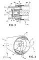
figure 2 est une section horizontale de l'organe de liaison et du conducteur tels que représentés à lafigure 1 ; - la
figure 3 est une représentation schématique en perspective de l'organe de liaison selon l'invention. - Dans la description qui va suivre, des éléments identiques, analogues ou similaires seront désignés par les mêmes références.
- A titre non limitatif et en vue de faciliter la compréhension de la description et des revendications, on adoptera les orientations Longitudinale, Transversale et Verticale en référence au repère L, T, V indiqué aux figures.
- On a représenté à la
figure 1 une extrémité avant d'un tronçon 30 d'une ligne de transport de courant électrique à moyenne, haute ou très haute tension. - Le tronçon 30 de la ligne de transport comporte principalement une enveloppe cylindrique 32 externe d'axe principal longitudinal et un conducteur de courant 14 d'axe principal A longitudinal sensiblement parallèle à l'axe principal de l'enveloppe externe 32.
- L'enveloppe externe 32 et le conducteur 14 sont réalisés en matériau conducteur électrique, par exemple en aluminium, et sont portés à des potentiels électriques différents.
- L'enveloppe externe 32 délimite un volume cylindrique qui est fermé et qui est rempli d'un gaz isolant sous pression limitant les risques de court-circuit avec le conducteur 14.
- Un organe de liaison 10 relie une extrémité de l'enveloppe externe 32 du tronçon 30, ici l'extrémité avant de l'enveloppe externe 32, avec une extrémité avant 12 du conducteur de courant 14.
- Le tronçon 30 de la ligne de transport est installé en extérieur, il est donc soumis aux conditions climatiques externes. Par conséquent, en fonction des conditions climatiques, le conducteur 14 et l'enveloppe 32 se dilatent, chacun selon des amplitudes différentes. Aussi, lorsqu'il est traversé par un courant électrique, le conducteur 14 se dilate.
- Ainsi, la longueur axiale du conducteur 14 varie par rapport à la longueur axiale de l'enveloppe 32, ce qui amène l'extrémité avant 12 du conducteur 14 à se déplacer longitudinalement par rapport à l'extrémité avant de l'enveloppe 32.
- L'organe de liaison 10 a pour fonction de guider l'extrémité avant 12 du conducteur 14 en déplacement longitudinal par rapport à l'extrémité avant de l'enveloppe 32, tout en supportant le poids du conducteur 14.
- Aussi, l'organe de liaison 10 est raccordé électriquement au conducteur 14 pour permettre le raccordement électrique de l'extrémité avant du tronçon 30.
- L'organe de liaison 10 est fixé à l'extrémité avant de l'enveloppe 32 par l'intermédiaire d'un support isolant 34 se présentant globalement sous la forme d'un élément coaxial à l'enveloppe 32, qui est étanche au gaz contenu dans l'enveloppe 32 et par un élément central métallique 36 auquel l'organe de liaison 10 est fixé.
- L'organe de liaison 10 comporte un corps 16 qui s'étend dans un plan transversal à l'axe principal A longitudinal du conducteur 14. Le corps 16 est fixé à l'élément central 36 du support isolant 34 de manière telle que l'organe de liaison 10 est raccordé électriquement à l'élément central 36.
- L'organe de liaison 10 comporte un bras 18 de guidage de l'extrémité avant 12 du conducteur 14, qui consiste globalement en une barre longitudinale, qui s'étend longitudinalement vers l'arrière depuis le corps 16 et qui est globalement coaxial à l'axe principal A du conducteur 14.
- L'extrémité arrière libre 20 du bras 18 est reçue à l'intérieur de l'extrémité avant 12 du conducteur 14 et elle coopère avec la surface interne 12i de l'extrémité avant 12 du conducteur 14 pour réaliser le guidage en déplacement longitudinal et le support verticalement du conducteur 14.
- Les dimensions radiales du bras 18 par rapport à l'axe longitudinal A sont inférieures au diamètre interne de l'extrémité avant 12 du conducteur 14.
- L'organe de liaison 10 comporte aussi une roue 22 qui est montée libre en rotation par rapport à l'extrémité arrière 20 du bras 18 autour d'un axe transversal B.
- La roue 22 est en appui vers le haut contre la surface interne 12i de l'extrémité avant 12 du conducteur 14.
- Le diamètre externe de la roue 22 est inférieur au diamètre interne de l'extrémité avant 12 du conducteur 14 et l'axe B de rotation de la roue 22 est situé verticalement au-dessus de l'axe principal A du conducteur 14.
- Aussi, comme on peut le voir aux
figures 2 et 3 , la surface annulaire externe de la roue 22 est bombée vers l'extérieur. - Ainsi, l'extrémité avant 12 du conducteur 14 repose verticalement vers le bas sur la roue 22, le contact de la roue 22 avec la surface interne 12i de l'extrémité avant 12 du conducteur 14 est située dans la partie supérieure de l'extrémité avant 12 du conducteur 14.
- Comme on peut le voir à la
figure 2 , la roue 22 est centrée transversalement par rapport à l'axe principal du conducteur 14 et de l'organe de liaison 10. Ainsi, les efforts produits par l'extrémité avant 12 du conducteur 14 sont orientés dans le plan principal médian de la roue 22. - Lors du déplacement longitudinal de l'extrémité avant 12 du conducteur 14 par rapport à l'organe de liaison 10, l'extrémité avant 12 du conducteur 14 roule sur la roue 22.
- Il n'y a donc aucun frottement entre le conducteur 14 et l'organe de liaison 10.
- Aussi, l'orientation de l'axe B de rotation de la roue 22 permet de guider l'extrémité avant 12 du conducteur 14 le long de la direction longitudinale L.
- L'organe de liaison 10 est conçu pour permettre une grande amplitude de déplacement de l'extrémité avant 12 du conducteur 14 selon la direction longitudinale.
- De préférence, l'organe de liaison 10 est réalisé de manière à permettre un déplacement longitudinal d'environ 350 mm de l'extrémité avant 12 du conducteur 14 par rapport à l'extrémité avant de l'enveloppe, c'est à dire que la course de l'extrémité avant 12 du conducteur 14 par rapport à l'organe de liaison 10 est d'environ 350 mm.
- A cet effet, la longueur du bras 18 est définie de manière que la distance entre l'axe B de rotation de la roue 22 et le corps 16 de l'organe de liaison 10 est supérieure à la course de 350 mm de l'extrémité avant 12 du conducteur 14 par rapport à l'organe de liaison 10.
- Comme dit précédemment, l'organe de liaison 10 est raccordé électriquement au connecteur 14, pour permettre le raccordement électrique du tronçon 30 avec un composant électrique agencé en avant du tronçon 30, par exemple avec un autre tronçon similaire de la ligne de transport.
- Pour cela, l'organe de liaison 10 est réalisé en un matériau conducteur électrique, par exemple en aluminium, et il comporte une pluralité de lames conductrices 24 qui sont en contact avec la surface cylindrique externe 12e de l'extrémité avant 12 du conducteur 14.
- Les lames 24 sont portées par un manchon 26 cylindrique qui est globalement coaxial au bras 18 et qui s'étend longitudinalement vers l'arrière depuis le corps 16.
- Les lames 24 sont agencées au niveau de l'extrémité arrière libre du manchon 26, et elles sont réparties sur le pourtour de l'extrémité arrière 26a du manchon 26.
- Le nombre de lames 24 est relativement important, pour réduire la résistance électrique de la liaison entre le conducteur 14 et l'organe de liaison.
- Comme on peut le voir aux figures, chaque lame 24 s'étend globalement longitudinalement vers l'arrière depuis l'extrémité arrière 26a du manchon 26 et elle est recourbée radialement vers l'intérieur selon l'axe principal longitudinal du manchon 26.
- L'extrémité arrière 24a de chaque lame 24 est donc plus proche radialement de l'axe principal A du manchon 26 que l'extrémité avant de la lame 24.
- Les lames 24 sont réalisées de manière qu'en position de repos, c'est-à-dire en l'absence du conducteur 14, l'extrémité arrière 24a de chaque lame 24 est située à une cote radiale inférieure au rayon de la surface externe 12e du conducteur 14. Ainsi, en présence du conducteur 14, chaque lame 24 est déformée élastiquement et exerce un effort élastique de pression de son extrémité arrière 24a sur la surface externe 12e du conducteur 14.
- A titre de variante de réalisation, cet effort élastique est renforcé au besoin par un ressort annulaire (non représenté) qui est disposé sur le pourtour des lames 24.
- Le diamètre interne du manchon 26 est supérieur au diamètre externe du conducteur 14. Le jeu radial entre le manchon 26 et le conducteur 14 permet à l'extrémité avant 12 du conducteur 14 de se déplacer à l'intérieur du manchon 26, et permet aussi une dilatation radiale de l'extrémité avant 12 du conducteur 14.
- Le bras 18, et la roue 22 supportent le poids du conducteur 14. Le bras 18 se déforme élastiquement en fléchissant vers le bas.
- Le jeu radial entre le manchon 26 et le conducteur 14 est défini pour permettre un déplacement vertical vers le bas de l'extrémité avant 12 du conducteur 14 du fait de cette déformation élastique du bras 18, et plus généralement pour permettre un défaut de coaxialité entre le manchon 26 et le conducteur 14.
- Ainsi, ni le guidage en translation axiale de l'extrémité avant 12 du conducteur 14, ni le raccordement électrique de l'organe de liaison 10 avec le conducteur 16 ne sont dégradés.
- Puisque les lames 24 sont réalisées en matériau déformable élastiquement, elles restent en contact sur la face externe 12e de l'extrémité avant 12 du conducteur, quelle que soit la position de l'axe principal A du conducteur 14 par rapport à l'organe de liaison 10, et aussi quelle que soit le niveau de dilatation radiale du conducteur 14.
- L'organe de liaison 10 comporte un couvercle annulaire 28 qui est monté sur l'extrémité arrière 26a du manchon 26 de manière à prolonger le manchon 26 vers l'arrière, et qui recouvre radialement les lames 24. Le couvercle annulaire 28 permet de fixer les lames 24 au manchon 26 par sertissage afin d'obtenir un ensemble diélectriquement acceptable
- L'extrémité arrière libre 28a du couvercle 28 est située axialement en arrière des extrémités arrière 24a des lames 24 et est resserrée radialement pour se rapprocher de la surface externe 12e de l'extrémité avant 12 du conducteur 14. Le couvercle 28, forme ainsi un réceptacle annulaire situé dessous les extrémités arrière des lames 24.
- Les particules pouvant éventuellement se former par frottement des lames 24 sur le conducteur tombent ainsi dans ce réceptacle formé par le couvercle 28, sous l'action de la gravité terrestre.
- Selon une variante de réalisation, l'extrémité arrière libre 28a du couvercle 28 porte en outre un joint annulaire du type racleur (non représenté), qui est comprimé entre l'extrémité arrière 28a du couvercle 28 et la surface cylindrique externe 12e de l'extrémité avant 12 du conducteur 14 pour éviter que les particules ne sortent vers l'extérieur du couvercle 28.
- Il sera compris que l'invention n'est pas limitée à ce seul mode de réalisation selon lequel l'organe de liaison 10 comporte une roue 22 pour supporter et guider l'extrémité avant 12 du conducteur 14 et que l'invention concerne tout composant apte à rouler sur la surface interne du conducteur.
- Ainsi, selon une variante de réalisation non représentée, l'organe de liaison 10 comporte une bille qui est portée par l'extrémité libre 20 du bras, et qui est libre en rotation par rapport à l'extrémité libre du bras 18.
- Selon une autre variante non représentée, l'organe de liaison 10 comporte plusieurs roues 22 alignées longitudinalement, ce qui permet de limiter les efforts subis par chaque roue 22 et augmenter leur durée de vie.
- De plus il sera compris que l'invention n'est pas limitée à ce seul mode de réalisation selon lequel la liaison électrique entre l'organe de liaison 10 et le conducteur 12 comporte une pluralité de lames conductrices 24 qui sont en contact avec la surface cylindrique externe 12e de l'extrémité avant 12 du conducteur 14, et que l'invention concerne tout organe de liaison comportant des moyens aptes à réaliser une liaison électrique tels que par exemple des contacts ressorts ou des doigts de contact assemblés par ressort.
- Selon encore une autre variante de réalisation de l'invention, l'extrémité arrière 20 et le bras 18 sont réalisés d'une seule pièce.
Claims (10)
- Ligne de transport de courant électrique comportant une enveloppe (32) cylindrique externe d'axe principal longitudinal, un conducteur (14) cylindrique d'axe principal(A) longitudinal sensiblement parallèle à l'axe principal de l'enveloppe (32), qui est agencé à l'intérieur de l'enveloppe (32),
et un organe de liaison (10) d'une extrémité longitudinale avant (12) du conducteur (14) à une extrémité longitudinale avant de l'enveloppe (32) externe qui est réalisé de manière à guider l'extrémité avant (12) du conducteur (14) en déplacement dans l'extrémité avant de l'enveloppe (32) au moins selon la direction longitudinale,
l'organe de liaison (10) comportant un corps (16) qui est fixé à l'extrémité avant de l'enveloppe (32) et comportant un bras (18) de guidage de l'extrémité avant (12) du conducteur (14) qui s'étend longitudinalement vers l'arrière depuis le corps (16) et dont l'extrémité arrière libre (20) est reçue à l'intérieur de l'extrémité avant (12) du conducteur (14) pour coopérer avec une surface cylindrique interne (12i) de l'extrémité avant (12) du conducteur (14),
caractérisée en ce que l'extrémité arrière (20) du bras (18) porte au moins un élément de guidage linéaire (22) qui est monté libre en rotation par rapport à l'extrémité arrière (20) du bras (18) autour d'au moins un axe transversal (B) et en ce que l'extrémité avant (12) du conducteur (14) repose verticalement vers le bas sur ledit organe de guidage (22) au niveau de sa surface cylindrique interne (12i). - Ligne de transport de courant électrique selon la revendication précédente, caractérisée en ce que l'élément de guidage (22) consiste en une roue montée libre en rotation par rapport à l'organe de liaison (10) autour d'un axe transversal (B) qui supporte l'extrémité avant (12) du conducteur (14).
- Ligne de transport de courant électrique selon la revendication précédente, caractérisée en ce que le diamètre de la roue (22) est inférieur au diamètre interne de l'extrémité avant (12) du conducteur (14) et en ce que l'axe transversal (B) de rotation de la roue (22) est situé verticalement au-dessus de l'axe longitudinal (A) de l'extrémité avant (12) du conducteur (14).
- Ligne de transport de courant électrique selon l'une quelconque des revendications précédentes, caractérisée en ce que l'organe de liaison (10) est raccordé électriquement avec le conducteur (14).
- Ligne de transport de courant électrique selon la revendication précédente, caractérisée en ce que l'organe de liaison (10) comporte des lames (24) métalliques dont une extrémité (24a) de chaque lame (24) est en contact glissant sur la face cylindrique externe (12e) du conducteur (14).
- Ligne de transport de courant électrique selon l'une quelconque des revendications précédentes, caractérisée en ce que l'extrémité libre (24a) de chaque lame (24) est en appui élastique sur la face cylindrique externe (12e) du conducteur (14).
- Ligne de transport de courant électrique selon l'une quelconque des revendications 5 ou 6, caractérisée en ce que les lames (24) sont portées par un manchon cylindrique (26) qui s'étend longitudinalement vers l'arrière depuis le corps (16) de l'organe de liaison (10) et dont le diamètre intérieur du manchon (26) est supérieur au diamètre de l'extrémité avant (12) du conducteur (14).
- Ligne de transport de courant électrique selon l'une quelconque des revendications 5 à 7, caractérisée en ce que l'organe de liaison (10) comporte une pluralité de lames (24) réparties sur le pourtour de l'extrémité longitudinale arrière (26a) libre du manchon (26) et en ce que chaque lame (24) s'étend longitudinalement vers l'arrière et radialement vers l'intérieur du manchon (26), depuis l'extrémité arrière (26a) du manchon (26).
- Ligne de transport de courant électrique selon la revendication précédente, caractérisée en ce que les lames (24) sont fixées à l'organe de liaison (10) par sertissage par l'intermédiaire d'un couvercle annulaire (28) qui est monté sur l'extrémité arrière (26a) du manchon (26) et qui recouvre longitudinalement et radialement les lames (24).
- Ligne de transport de courant électrique selon l'une quelconque des revendications précédentes, caractérisée en ce que le corps (16) de l'organe de liaison (10) est fixé à l'enveloppe (32) par l'intermédiaire d'un support (34) isolant électriquement comportant un élément central métallique(36)auquel le corps (16) de l'organe de liaison (10) est fixé.
Applications Claiming Priority (1)
| Application Number | Priority Date | Filing Date | Title |
|---|---|---|---|
| FR1158062A FR2980050B1 (fr) | 2011-09-12 | 2011-09-12 | Ligne de transport de courant comportant des moyens de guidage de l'extremite du conducteur interne |
Publications (2)
| Publication Number | Publication Date |
|---|---|
| EP2568555A1 true EP2568555A1 (fr) | 2013-03-13 |
| EP2568555B1 EP2568555B1 (fr) | 2016-03-16 |
Family
ID=46762991
Family Applications (1)
| Application Number | Title | Priority Date | Filing Date |
|---|---|---|---|
| EP12183696.9A Not-in-force EP2568555B1 (fr) | 2011-09-12 | 2012-09-10 | Ligne de transport de courant comportant des moyens de guidage de l'extremite du conducteur interne |
Country Status (2)
| Country | Link |
|---|---|
| EP (1) | EP2568555B1 (fr) |
| FR (1) | FR2980050B1 (fr) |
Citations (5)
| Publication number | Priority date | Publication date | Assignee | Title |
|---|---|---|---|---|
| DE2339554A1 (de) * | 1973-08-02 | 1975-02-20 | Siemens Ag | Gekapselte, gasisolierte hochspannungsleitung |
| DE7323367U (de) * | 1973-06-22 | 1975-04-03 | Siemens Ag | Leiterexpansionsstelle einer gekapselten Hochspannungsleitung |
| US4431886A (en) * | 1981-08-12 | 1984-02-14 | Northern Engineering Industries Plc | Circuit-breaker |
| DE3835990A1 (de) * | 1987-10-26 | 1989-05-03 | Mitsubishi Electric Corp | Stromschienenverbinder |
| US6118068A (en) * | 1996-03-19 | 2000-09-12 | Siemens Aktiengesellschaft | Gas-insulated power transmission system with internal conductors fixed axially at intervals |
-
2011
- 2011-09-12 FR FR1158062A patent/FR2980050B1/fr not_active Expired - Fee Related
-
2012
- 2012-09-10 EP EP12183696.9A patent/EP2568555B1/fr not_active Not-in-force
Patent Citations (5)
| Publication number | Priority date | Publication date | Assignee | Title |
|---|---|---|---|---|
| DE7323367U (de) * | 1973-06-22 | 1975-04-03 | Siemens Ag | Leiterexpansionsstelle einer gekapselten Hochspannungsleitung |
| DE2339554A1 (de) * | 1973-08-02 | 1975-02-20 | Siemens Ag | Gekapselte, gasisolierte hochspannungsleitung |
| US4431886A (en) * | 1981-08-12 | 1984-02-14 | Northern Engineering Industries Plc | Circuit-breaker |
| DE3835990A1 (de) * | 1987-10-26 | 1989-05-03 | Mitsubishi Electric Corp | Stromschienenverbinder |
| US6118068A (en) * | 1996-03-19 | 2000-09-12 | Siemens Aktiengesellschaft | Gas-insulated power transmission system with internal conductors fixed axially at intervals |
Also Published As
| Publication number | Publication date |
|---|---|
| FR2980050B1 (fr) | 2013-10-04 |
| FR2980050A1 (fr) | 2013-03-15 |
| EP2568555B1 (fr) | 2016-03-16 |
Similar Documents
| Publication | Publication Date | Title |
|---|---|---|
| CA2891072A1 (fr) | Support de tube d'evacuation d'air dans une turbomachine | |
| FR2775741A1 (fr) | Organe de transmission mecanique et son application a un joint mecanique homocinetique | |
| EP2568555B1 (fr) | Ligne de transport de courant comportant des moyens de guidage de l'extremite du conducteur interne | |
| FR3051854A1 (fr) | Carter d'echappement de turbomachine | |
| EP1673243B1 (fr) | Suspensions de vehicule a raideur variable | |
| EP0282406A1 (fr) | Dispositif pour le maintien en position d'une extrémité d'un élément monté mobile en rotation dans un tube et application de ce dispositif | |
| FR2947218A1 (fr) | Assemblage de transmission de vehicule automobile, notamment ferroviaire | |
| EP1787041B1 (fr) | Agencement pour la fixation d'un mecanisme d'essuyage | |
| EP2969607B1 (fr) | Coupelle de ressort | |
| EP3172474B1 (fr) | Joint de dilatation pour gaine d'isolation au gaz avec reprise d'effet de fond | |
| FR2937587A1 (fr) | Jambe de suspension de vehicule et butee associee | |
| EP2733340B1 (fr) | Tige filetée d'un système de déploiement d'un divergent déployable de propulseur | |
| CA2857729C (fr) | Dispositif de couplage d'une roue motorisee de train d'atterrissage d'aeronef | |
| EP0642145B1 (fr) | Contact électrique de type tulipe | |
| FR2914600A1 (fr) | Butoir pour la protection d'un premier element lors de la rencontre avec un deuxieme element. | |
| EP0325073B1 (fr) | Dispositif de montage pour palier | |
| WO2003019735A1 (fr) | Dispositif de transmission electrique de systemes rotatifs | |
| EP2034209A1 (fr) | Coussinet élastique pour frein à disque | |
| FR3034046A1 (fr) | Dispositif de butee de suspension | |
| EP3050776A1 (fr) | Poussoir de direction assistée comprenant un ressort de rappel pourvu d'un enrobage élastomère amortisseur | |
| EP0712743A1 (fr) | Dispositif anti-dévers pour essieu de véhicule automobile | |
| EP4180239B1 (fr) | Dispositif de roulement pour un véhicule terrestre | |
| FR3001498A1 (fr) | Partie fixe de recepteur de turbomachine comprenant un ensemble de maintien en position de servitudes a l'interieur d'un arbre creux fixe | |
| FR3079553A1 (fr) | Ensemble pour turbomachine | |
| FR2578972A1 (fr) | Monture pour supporter une sonde dans un reservoir |
Legal Events
| Date | Code | Title | Description |
|---|---|---|---|
| PUAI | Public reference made under article 153(3) epc to a published international application that has entered the european phase |
Free format text: ORIGINAL CODE: 0009012 |
|
| AK | Designated contracting states |
Kind code of ref document: A1 Designated state(s): AL AT BE BG CH CY CZ DE DK EE ES FI FR GB GR HR HU IE IS IT LI LT LU LV MC MK MT NL NO PL PT RO RS SE SI SK SM TR |
|
| AX | Request for extension of the european patent |
Extension state: BA ME |
|
| 17P | Request for examination filed |
Effective date: 20130903 |
|
| RBV | Designated contracting states (corrected) |
Designated state(s): AL AT BE BG CH CY CZ DE DK EE ES FI FR GB GR HR HU IE IS IT LI LT LU LV MC MK MT NL NO PL PT RO RS SE SI SK SM TR |
|
| GRAP | Despatch of communication of intention to grant a patent |
Free format text: ORIGINAL CODE: EPIDOSNIGR1 |
|
| RIC1 | Information provided on ipc code assigned before grant |
Ipc: H02G 5/06 20060101AFI20150824BHEP |
|
| INTG | Intention to grant announced |
Effective date: 20150908 |
|
| GRAS | Grant fee paid |
Free format text: ORIGINAL CODE: EPIDOSNIGR3 |
|
| GRAA | (expected) grant |
Free format text: ORIGINAL CODE: 0009210 |
|
| AK | Designated contracting states |
Kind code of ref document: B1 Designated state(s): AL AT BE BG CH CY CZ DE DK EE ES FI FR GB GR HR HU IE IS IT LI LT LU LV MC MK MT NL NO PL PT RO RS SE SI SK SM TR |
|
| REG | Reference to a national code |
Ref country code: GB Ref legal event code: FG4D Free format text: NOT ENGLISH |
|
| REG | Reference to a national code |
Ref country code: CH Ref legal event code: EP Ref country code: CH Ref legal event code: NV Representative=s name: BOVARD AG, CH |
|
| REG | Reference to a national code |
Ref country code: IE Ref legal event code: FG4D Free format text: LANGUAGE OF EP DOCUMENT: FRENCH |
|
| RAP2 | Party data changed (patent owner data changed or rights of a patent transferred) |
Owner name: GENERAL ELECTRIC TECHNOLOGY GMBH |
|
| REG | Reference to a national code |
Ref country code: AT Ref legal event code: REF Ref document number: 781954 Country of ref document: AT Kind code of ref document: T Effective date: 20160415 |
|
| REG | Reference to a national code |
Ref country code: DE Ref legal event code: R081 Ref document number: 602012015600 Country of ref document: DE Owner name: GENERAL ELECTRIC TECHNOLOGY GMBH, CH Free format text: FORMER OWNER: ALSTOM TECHNOLOGY LTD., BADEN, CH |
|
| REG | Reference to a national code |
Ref country code: DE Ref legal event code: R096 Ref document number: 602012015600 Country of ref document: DE |
|
| REG | Reference to a national code |
Ref country code: NL Ref legal event code: MP Effective date: 20160316 |
|
| REG | Reference to a national code |
Ref country code: LT Ref legal event code: MG4D |
|
| PG25 | Lapsed in a contracting state [announced via postgrant information from national office to epo] |
Ref country code: GR Free format text: LAPSE BECAUSE OF FAILURE TO SUBMIT A TRANSLATION OF THE DESCRIPTION OR TO PAY THE FEE WITHIN THE PRESCRIBED TIME-LIMIT Effective date: 20160617 Ref country code: HR Free format text: LAPSE BECAUSE OF FAILURE TO SUBMIT A TRANSLATION OF THE DESCRIPTION OR TO PAY THE FEE WITHIN THE PRESCRIBED TIME-LIMIT Effective date: 20160316 Ref country code: FI Free format text: LAPSE BECAUSE OF FAILURE TO SUBMIT A TRANSLATION OF THE DESCRIPTION OR TO PAY THE FEE WITHIN THE PRESCRIBED TIME-LIMIT Effective date: 20160316 Ref country code: NO Free format text: LAPSE BECAUSE OF FAILURE TO SUBMIT A TRANSLATION OF THE DESCRIPTION OR TO PAY THE FEE WITHIN THE PRESCRIBED TIME-LIMIT Effective date: 20160616 |
|
| REG | Reference to a national code |
Ref country code: AT Ref legal event code: MK05 Ref document number: 781954 Country of ref document: AT Kind code of ref document: T Effective date: 20160316 |
|
| PG25 | Lapsed in a contracting state [announced via postgrant information from national office to epo] |
Ref country code: LT Free format text: LAPSE BECAUSE OF FAILURE TO SUBMIT A TRANSLATION OF THE DESCRIPTION OR TO PAY THE FEE WITHIN THE PRESCRIBED TIME-LIMIT Effective date: 20160316 Ref country code: LV Free format text: LAPSE BECAUSE OF FAILURE TO SUBMIT A TRANSLATION OF THE DESCRIPTION OR TO PAY THE FEE WITHIN THE PRESCRIBED TIME-LIMIT Effective date: 20160316 Ref country code: SE Free format text: LAPSE BECAUSE OF FAILURE TO SUBMIT A TRANSLATION OF THE DESCRIPTION OR TO PAY THE FEE WITHIN THE PRESCRIBED TIME-LIMIT Effective date: 20160316 Ref country code: RS Free format text: LAPSE BECAUSE OF FAILURE TO SUBMIT A TRANSLATION OF THE DESCRIPTION OR TO PAY THE FEE WITHIN THE PRESCRIBED TIME-LIMIT Effective date: 20160316 Ref country code: NL Free format text: LAPSE BECAUSE OF FAILURE TO SUBMIT A TRANSLATION OF THE DESCRIPTION OR TO PAY THE FEE WITHIN THE PRESCRIBED TIME-LIMIT Effective date: 20160316 |
|
| REG | Reference to a national code |
Ref country code: FR Ref legal event code: PLFP Year of fee payment: 5 |
|
| PG25 | Lapsed in a contracting state [announced via postgrant information from national office to epo] |
Ref country code: PL Free format text: LAPSE BECAUSE OF FAILURE TO SUBMIT A TRANSLATION OF THE DESCRIPTION OR TO PAY THE FEE WITHIN THE PRESCRIBED TIME-LIMIT Effective date: 20160316 Ref country code: EE Free format text: LAPSE BECAUSE OF FAILURE TO SUBMIT A TRANSLATION OF THE DESCRIPTION OR TO PAY THE FEE WITHIN THE PRESCRIBED TIME-LIMIT Effective date: 20160316 Ref country code: IS Free format text: LAPSE BECAUSE OF FAILURE TO SUBMIT A TRANSLATION OF THE DESCRIPTION OR TO PAY THE FEE WITHIN THE PRESCRIBED TIME-LIMIT Effective date: 20160716 |
|
| PGFP | Annual fee paid to national office [announced via postgrant information from national office to epo] |
Ref country code: CH Payment date: 20160927 Year of fee payment: 5 |
|
| PG25 | Lapsed in a contracting state [announced via postgrant information from national office to epo] |
Ref country code: RO Free format text: LAPSE BECAUSE OF FAILURE TO SUBMIT A TRANSLATION OF THE DESCRIPTION OR TO PAY THE FEE WITHIN THE PRESCRIBED TIME-LIMIT Effective date: 20160316 Ref country code: AT Free format text: LAPSE BECAUSE OF FAILURE TO SUBMIT A TRANSLATION OF THE DESCRIPTION OR TO PAY THE FEE WITHIN THE PRESCRIBED TIME-LIMIT Effective date: 20160316 Ref country code: ES Free format text: LAPSE BECAUSE OF FAILURE TO SUBMIT A TRANSLATION OF THE DESCRIPTION OR TO PAY THE FEE WITHIN THE PRESCRIBED TIME-LIMIT Effective date: 20160316 Ref country code: SM Free format text: LAPSE BECAUSE OF FAILURE TO SUBMIT A TRANSLATION OF THE DESCRIPTION OR TO PAY THE FEE WITHIN THE PRESCRIBED TIME-LIMIT Effective date: 20160316 Ref country code: SK Free format text: LAPSE BECAUSE OF FAILURE TO SUBMIT A TRANSLATION OF THE DESCRIPTION OR TO PAY THE FEE WITHIN THE PRESCRIBED TIME-LIMIT Effective date: 20160316 Ref country code: CZ Free format text: LAPSE BECAUSE OF FAILURE TO SUBMIT A TRANSLATION OF THE DESCRIPTION OR TO PAY THE FEE WITHIN THE PRESCRIBED TIME-LIMIT Effective date: 20160316 Ref country code: PT Free format text: LAPSE BECAUSE OF FAILURE TO SUBMIT A TRANSLATION OF THE DESCRIPTION OR TO PAY THE FEE WITHIN THE PRESCRIBED TIME-LIMIT Effective date: 20160718 |
|
| PGFP | Annual fee paid to national office [announced via postgrant information from national office to epo] |
Ref country code: FR Payment date: 20160926 Year of fee payment: 5 |
|
| REG | Reference to a national code |
Ref country code: DE Ref legal event code: R097 Ref document number: 602012015600 Country of ref document: DE |
|
| PG25 | Lapsed in a contracting state [announced via postgrant information from national office to epo] |
Ref country code: IT Free format text: LAPSE BECAUSE OF FAILURE TO SUBMIT A TRANSLATION OF THE DESCRIPTION OR TO PAY THE FEE WITHIN THE PRESCRIBED TIME-LIMIT Effective date: 20160316 |
|
| PLBE | No opposition filed within time limit |
Free format text: ORIGINAL CODE: 0009261 |
|
| STAA | Information on the status of an ep patent application or granted ep patent |
Free format text: STATUS: NO OPPOSITION FILED WITHIN TIME LIMIT |
|
| PG25 | Lapsed in a contracting state [announced via postgrant information from national office to epo] |
Ref country code: DK Free format text: LAPSE BECAUSE OF FAILURE TO SUBMIT A TRANSLATION OF THE DESCRIPTION OR TO PAY THE FEE WITHIN THE PRESCRIBED TIME-LIMIT Effective date: 20160316 |
|
| PGFP | Annual fee paid to national office [announced via postgrant information from national office to epo] |
Ref country code: DE Payment date: 20160928 Year of fee payment: 5 |
|
| 26N | No opposition filed |
Effective date: 20161219 |
|
| PG25 | Lapsed in a contracting state [announced via postgrant information from national office to epo] |
Ref country code: BG Free format text: LAPSE BECAUSE OF FAILURE TO SUBMIT A TRANSLATION OF THE DESCRIPTION OR TO PAY THE FEE WITHIN THE PRESCRIBED TIME-LIMIT Effective date: 20160616 Ref country code: BE Free format text: LAPSE BECAUSE OF NON-PAYMENT OF DUE FEES Effective date: 20160930 |
|
| PG25 | Lapsed in a contracting state [announced via postgrant information from national office to epo] |
Ref country code: MC Free format text: LAPSE BECAUSE OF FAILURE TO SUBMIT A TRANSLATION OF THE DESCRIPTION OR TO PAY THE FEE WITHIN THE PRESCRIBED TIME-LIMIT Effective date: 20160316 |
|
| GBPC | Gb: european patent ceased through non-payment of renewal fee |
Effective date: 20160910 |
|
| PG25 | Lapsed in a contracting state [announced via postgrant information from national office to epo] |
Ref country code: SI Free format text: LAPSE BECAUSE OF FAILURE TO SUBMIT A TRANSLATION OF THE DESCRIPTION OR TO PAY THE FEE WITHIN THE PRESCRIBED TIME-LIMIT Effective date: 20160316 |
|
| REG | Reference to a national code |
Ref country code: IE Ref legal event code: MM4A |
|
| PG25 | Lapsed in a contracting state [announced via postgrant information from national office to epo] |
Ref country code: IE Free format text: LAPSE BECAUSE OF NON-PAYMENT OF DUE FEES Effective date: 20160910 Ref country code: GB Free format text: LAPSE BECAUSE OF NON-PAYMENT OF DUE FEES Effective date: 20160910 |
|
| PG25 | Lapsed in a contracting state [announced via postgrant information from national office to epo] |
Ref country code: LU Free format text: LAPSE BECAUSE OF NON-PAYMENT OF DUE FEES Effective date: 20160910 |
|
| REG | Reference to a national code |
Ref country code: BE Ref legal event code: MM Effective date: 20160930 |
|
| REG | Reference to a national code |
Ref country code: DE Ref legal event code: R119 Ref document number: 602012015600 Country of ref document: DE |
|
| REG | Reference to a national code |
Ref country code: CH Ref legal event code: PL |
|
| PG25 | Lapsed in a contracting state [announced via postgrant information from national office to epo] |
Ref country code: HU Free format text: LAPSE BECAUSE OF FAILURE TO SUBMIT A TRANSLATION OF THE DESCRIPTION OR TO PAY THE FEE WITHIN THE PRESCRIBED TIME-LIMIT; INVALID AB INITIO Effective date: 20120910 Ref country code: CY Free format text: LAPSE BECAUSE OF FAILURE TO SUBMIT A TRANSLATION OF THE DESCRIPTION OR TO PAY THE FEE WITHIN THE PRESCRIBED TIME-LIMIT Effective date: 20160316 |
|
| PG25 | Lapsed in a contracting state [announced via postgrant information from national office to epo] |
Ref country code: TR Free format text: LAPSE BECAUSE OF FAILURE TO SUBMIT A TRANSLATION OF THE DESCRIPTION OR TO PAY THE FEE WITHIN THE PRESCRIBED TIME-LIMIT Effective date: 20160316 Ref country code: MT Free format text: LAPSE BECAUSE OF FAILURE TO SUBMIT A TRANSLATION OF THE DESCRIPTION OR TO PAY THE FEE WITHIN THE PRESCRIBED TIME-LIMIT Effective date: 20160316 Ref country code: MK Free format text: LAPSE BECAUSE OF FAILURE TO SUBMIT A TRANSLATION OF THE DESCRIPTION OR TO PAY THE FEE WITHIN THE PRESCRIBED TIME-LIMIT Effective date: 20160316 |
|
| REG | Reference to a national code |
Ref country code: FR Ref legal event code: ST Effective date: 20180531 |
|
| PG25 | Lapsed in a contracting state [announced via postgrant information from national office to epo] |
Ref country code: DE Free format text: LAPSE BECAUSE OF NON-PAYMENT OF DUE FEES Effective date: 20180404 Ref country code: CH Free format text: LAPSE BECAUSE OF NON-PAYMENT OF DUE FEES Effective date: 20170930 Ref country code: LI Free format text: LAPSE BECAUSE OF NON-PAYMENT OF DUE FEES Effective date: 20170930 |
|
| PG25 | Lapsed in a contracting state [announced via postgrant information from national office to epo] |
Ref country code: FR Free format text: LAPSE BECAUSE OF NON-PAYMENT OF DUE FEES Effective date: 20171002 |
|
| PG25 | Lapsed in a contracting state [announced via postgrant information from national office to epo] |
Ref country code: AL Free format text: LAPSE BECAUSE OF FAILURE TO SUBMIT A TRANSLATION OF THE DESCRIPTION OR TO PAY THE FEE WITHIN THE PRESCRIBED TIME-LIMIT Effective date: 20160316 |