EP2568441A1 - Tomographic image generating apparatus and tomographic image generating method - Google Patents
Tomographic image generating apparatus and tomographic image generating method Download PDFInfo
- Publication number
- EP2568441A1 EP2568441A1 EP12183363A EP12183363A EP2568441A1 EP 2568441 A1 EP2568441 A1 EP 2568441A1 EP 12183363 A EP12183363 A EP 12183363A EP 12183363 A EP12183363 A EP 12183363A EP 2568441 A1 EP2568441 A1 EP 2568441A1
- Authority
- EP
- European Patent Office
- Prior art keywords
- tomographic image
- region
- pixels
- projection
- radiation
- Prior art date
- Legal status (The legal status is an assumption and is not a legal conclusion. Google has not performed a legal analysis and makes no representation as to the accuracy of the status listed.)
- Withdrawn
Links
Images








Classifications
-
- G—PHYSICS
- G06—COMPUTING OR CALCULATING; COUNTING
- G06T—IMAGE DATA PROCESSING OR GENERATION, IN GENERAL
- G06T12/00—Tomographic reconstruction from projections
- G06T12/10—Image preprocessing, e.g. calibration, positioning of sources or scatter correction
-
- G—PHYSICS
- G06—COMPUTING OR CALCULATING; COUNTING
- G06T—IMAGE DATA PROCESSING OR GENERATION, IN GENERAL
- G06T2211/00—Image generation
- G06T2211/40—Computed tomography
- G06T2211/432—Truncation
-
- G—PHYSICS
- G06—COMPUTING OR CALCULATING; COUNTING
- G06T—IMAGE DATA PROCESSING OR GENERATION, IN GENERAL
- G06T2211/00—Image generation
- G06T2211/40—Computed tomography
- G06T2211/436—Limited angle
Definitions
- the present invention relates to an apparatus for and a method of generating a tomographic image.
- Japanese Laid-Open Patent Publication No. 2004-121853 discloses a method of and an apparatus for reconstructing an image in an external area of a field of view by enhancing partially sampled field-of-view data using fully sampled field-of-view data. Since the disclosed method and apparatus is capable of expanding the range that can be represented as a tomographic image, the disclosed method and apparatus is highly convenient for use in diagnostic applications.
- Japanese Laid-Open Patent Publication No. 2005-152658 discloses an apparatus for and a method of assigning irregular coefficients to respective sliced positions (equivalent to respective pixels) of backprojection data, and performing a product-sum operation on acquired projection image data in order to generate a tomographic image.
- Japanese Laid-Open Patent Publication No. 2008-200273 reveals an apparatus for and a method of replacing the values of pixels, which are judged as forming an incompletely focused area (partially sampled field-of-view data), with a prescribed constant value in order to fill in such pixels.
- Japanese Laid-Open Patent Publication No. 2004-121853 Japanese Laid-Open Patent Publication No. 2005-152658
- Japanese Laid-Open Patent Publication No. 2008-200273 are disadvantageous in that the amount of processed data required to generate a tomographic image increases, and to the extent that a long waiting time is required from the end of the image capturing process until the start of the diagnostic process based on the generated tomographic image.
- a tomographic image generating apparatus comprising a radiation source for applying radiation to a subject, a radiation detector for detecting radiation that has passed through the subject and acquiring projection image data from the detected radiation, and tomographic image generating means for generating a tomographic image in a region of interest disposed in the subject and interposed between the radiation source and the radiation detector, using a plurality of projection image data acquired by the radiation detector in image capturing processes, which are carried out while a relative positional relationship between the radiation source and the radiation detector successively changes.
- the tomographic image generating means includes a data determiner for performing an extrapolating process on each of the acquired projection image data along a prescribed direction, and for performing a smoothing process on each of the acquired projection image data along a direction perpendicular to the prescribed direction, thereby determining values of a plurality of pixels in non-detecting regions, which do not belong to a detecting region of the radiation detector, the determined values of the pixels also being used to generate the tomographic image.
- the tomographic image can be generated without the need for special processing sequences. Since the smoothing process is performed along the direction perpendicular to the prescribed direction in order to determine the values of the pixels in the non-detecting regions, it is possible to reduce striped density irregularities that extend along the prescribed direction, which might otherwise be caused by the extrapolating process. Consequently, in a case where a tomographic image including expanded regions is generated, the amount of processed data required to generate the tomographic image can be reduced, and artifacts can be prevented from occurring in the tomographic image.
- the prescribed direction preferably comprises a direction projected onto a projection plane including the detecting region, and extending parallel to a direction of relative motion of the radiation source.
- the tomographic image generating means preferably further includes a projection region determiner for determining a projection region on the projection plane, onto which the radiation source projects the region of interest, based on information concerning the position of the region of interest and the relative positional relationship.
- the data determiner preferably determines values of a plurality of pixels in non-detecting regions, which belong to the projection region determined by the projection region determiner, and which do not belong to the detecting region.
- the projection region determiner preferably determines a projection region of one size irrespective of the relative positional relationship.
- the tomographic image generating means preferably further includes a data corrector for correcting a spectral intensity at each spatial frequency of the projection image data that exhibits geometric unsharpness due to the image capturing processes.
- the data corrector preferably corrects the projection image data before the data determiner determines the values of the pixels in the non-detecting regions.
- the data determiner preferably determines the values of the pixels in the non-detecting regions such that differences between the values of pixels adjacent to boundaries between the detecting region and the non-detecting regions fall within a prescribed range.
- the data determiner preferably performs a zeroth-order extrapolating process or a first-order extrapolating process to thereby determine the values of the pixels in the non-detecting regions.
- the tomographic image generating means preferably performs a blackening process on the tomographic image for bringing to a prescribed constant value the values of plural pixels that belong to a prescribed region existing within the region of interest.
- the data determiner preferably determines the values of the pixels in the non-detecting regions by performing the extrapolating process on a plurality of pixels in the detecting region, based on values produced by the smoothing process performed along the direction perpendicular to the prescribed direction.
- the data determiner preferably determines the values of the pixels in the non-detecting regions by performing the smoothing process along the direction perpendicular to the prescribed direction on a plurality of pixels in the non-detecting regions, the values of which are temporarily determined by the extrapolating process, after the extrapolating process has been performed.
- the tomographic image generating apparatus preferably further comprises a display unit for displaying marks indicative of a distribution of added numbers of pixels belonging to the detecting region and which are used to generate the tomographic image, the marks being displayed in overlapping relation to the tomographic image generated by the tomographic image generating means.
- a method of generating a tomographic image of a subject using a radiation source for applying radiation to the subject, and a radiation detector for detecting radiation that has passed through the subject and acquiring projection image data from the detected radiation, and by carrying out image capturing processes while a relative positional relationship between the radiation source and the radiation detector successively changes comprising the steps of acquiring a plurality of projection image data through the radiation detector, and performing an extrapolating process on each of the acquired projection image data along a prescribed direction, and performing a smoothing process on each of the acquired projection image data along a direction perpendicular to the prescribed direction, thereby determining values of a plurality of pixels in non-detecting regions, which do not belong to a detecting region of the radiation detector, the determined values of the pixels also being used to generate the tomographic image.
- an extrapolating process is performed on the acquired projection image data along the prescribed direction in order to generate a tomographic image without the need for any special processing sequences. Further, since a smoothing process along the direction perpendicular to the prescribed direction also is performed in order to determine values of the pixels in the non-detecting regions, it is possible to reduce striped density irregularities that extend along the prescribed direction, which might otherwise be caused by the extrapolating process. Consequently, in a case where a tomographic image including expanded regions is generated, the amount of processed data required to generate the tomographic image is reduced, and artifacts are prevented from occurring in the tomographic image.
- a tomographic image generating apparatus 10 basically includes a radiation detecting device 12, a projection image data acquiring assembly 14, an image reconstructor 16, and a console 18 for controlling the radiation detecting device 12, the projection image data acquiring assembly 14, and the image reconstructor 16.
- the projection image data acquiring assembly 14 includes a radiation source 20 disposed in confronting relation to the radiation detecting device 12, a moving mechanism 22 for moving the radiation source 20 successively to a plurality of preset positions, a radiation controller 28 for controlling the radiation source 20 to apply radiation 26 to a subject 24 over the radiation detecting device 12 at times coincident with the radiation source 20 reaching each of the preset positions, and an image storage unit 32 for storing in an image memory 30 a plurality of projection image data sent successively from the radiation detecting device 12.
- the image reconstructor 16 processes the plural projection image data stored in the image memory 30 in order to generate or reconstruct a tomographic image including a certain region 33 (hereinafter referred to as a "designated region 33") of the subject 24.
- the image reconstructor 16 supplies image data representing the tomographic image to a monitor 34 (display unit) for displaying the tomographic image.
- the radiation detecting device 12 includes a casing 36, a battery 38 (see FIG. 2 ) housed in the casing 36, a radiation detector 40 housed in the casing 36, and a detector controller 42 housed in the casing 36.
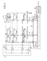
- the radiation detector 40 comprises an array of thin-film transistors (TFTs) 52 arranged in rows and columns, a photoelectric conversion layer 51 made of a material such as amorphous selenium (a-Se) for generating electric charges upon detection of radiation 26, the photoelectric conversion layer 51 being disposed on the array of TFTs 52, and an array of storage capacitors 53 connected to the photoelectric conversion layer 51.
- TFTs thin-film transistors
- a-Se amorphous selenium
- the photoelectric conversion layer 51 and one of the storage capacitors 53 are shown as a pixel 50, the pixel 50 being connected to one of the TFTs 52. Details of the other pixels 50 are omitted from illustration. Since amorphous selenium tends to change in structure and lose functions thereof at high temperatures, amorphous selenium needs to be used within a certain temperature range. Therefore, some means for cooling the radiation detector 40 should preferably be provided in the casing 36.
- the TFTs 52 which are connected to the respective pixels 50, are connected to respective gate lines 54 extending parallel to the rows, and to respective signal lines 56 extending parallel to the columns.
- the gate lines 54 are connected to a line scanning driver 58, and the signal lines 56 are connected to a multiplexer 66 that serves as a reading circuit.
- the gate lines 54 are supplied with control signals Von, Voff for turning on and off the TFTs 52 along the rows from the line scanning driver 58.
- the line scanning driver 58 comprises a plurality of first switches SW1 for switching between the gate lines 54, and an address decoder 60 for outputting a selection signal for selecting one of the first switches SW1 at a time.
- the address decoder 60 is supplied with an address signal from the detector controller 42.
- the signal lines 56 are supplied with electric charges stored in the storage capacitors 53 of the pixels 50 through the TFTs 52 arranged in the columns.
- the electric charges supplied to the signal lines 56 are amplified by amplifiers 62, which are connected respectively to the signal lines 56.
- the amplifiers 62 are connected through respective sample and hold circuits 64 to the multiplexer 66.
- the multiplexer 66 comprises a plurality of second switches SW2 for successively switching between the signal lines 56, and an address decoder 68 for outputting a selection signal for selecting one of the second switches SW2 at a time.
- the address decoder 68 is supplied with an address signal from the detector controller 42.
- the multiplexer 66 has an output terminal connected to an A/D converter 70.
- An image signal generated by the multiplexer 66 based on electric charges from the sample and hold circuits 64 is converted by the A/D converter 70 into a digital image signal (projection image data), which is supplied to the detector controller 42.
- the detector controller 42 supplies the projection image data to the image memory 30 (see FIG. 1 ), which stores the supplied projection image data.
- the radiation detecting device 12 outputs projection image data. Projection image data successively output from the radiation detecting device 12 are stored in the image memory 30 in chronological order, for example.
- the projection image data acquiring assembly 14 moves the radiation source 20 disposed in facing relation to the radiation detecting device 12 successively to a plurality of different positions. Each time that the radiation source 20 reaches one of the positions, the radiation source 20 applies radiation 26 to the subject 24 over the radiation detecting device 12, which detects radiation 26 that has passed through the subject 24, and generates projection image data of the subject 24 data based on the detected radiation 26. Therefore, as the radiation source 20 moves successively through the respective positions, the radiation source 20 applies radiation 26 to the subject 24 at different angles or in different directions, and the radiation detecting device 12 generates a plurality of projection image data of the subject 24.
- the tomographic image generating apparatus 10 includes the radiation source 20, which is movable with respect to the radiation detector 40 that is fixed in place. However, at least one of the radiation source 20 and the radiation detector 40 may be moved in order to capture a plurality of projection image data of the subject 24 at different angles.
- the radiation source 20 is shown as being moved and placed in three different positions, which are spaced along the longitudinal axis of the subject 24. However, the radiation source 20 may be moved and placed in two different positions, or in four or more different positions.
- the radiation source 20 is moved along a straight path interconnecting the different positions.
- the radiation source 20 may be moved along a curved path such as an arcuate path that interconnects the different positions.
- Image capturing processes referred to in the present invention include an individual image capturing process, which is carried out at a time when the radiation source 20 has reached each of the preset positions, and a collective image capturing process, which collectively represents a plurality of individual image capturing processes.
- Each individual image capturing process will be referred to as a "radiographic image capturing process”
- the collective image capturing process which collectively represents a plurality of individual image capturing processes, will be referred to as a "tomosynthetic image capturing process”.
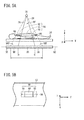
- FIG. 3A illustrates a radiographic image capturing process (a so-called scout image capturing process) with the radiation source 20 displaced to a frontal position.
- the designated region 33 in the subject 24 corresponds to a sectional region of a radiation field RF at a certain height (Z-axis position).
- the Z-axis extends vertically perpendicular to the longitudinal axis of the subject 24 who lies horizontally over the radiation detecting device 12
- the Y-axis extends along the longitudinal axis of the subject 24
- the X-axis extends horizontally transverse to the longitudinal axis of the subject 24 and perpendicular to the Z-axis and the Y-axis.
- the designated region 33 comprises a planar region which lies substantially parallel to a flat region (hereinafter referred to as a "detecting region 80") where the pixels 50 (see FIG.
- the designated region 33 With the designated region 33 being established at a certain position in the subject 24, a desired tomographic image of the designated region 33 is generated.
- the designated region 33 lies within a sectional plane 84 (see FIG. 4A ) in the subject 24.
- the designated region 33 becomes progressively smaller as the sectional plane 84 is shifted in a positive direction (upward direction) along the Z-axis.
- the designated region 33 as well as later-described expanded regions 90, 92 are illustrated as having a thickness along the Z-axis.
- a projection plane 82 is defined in common to projection image data that is used to generate a tomographic image.
- the projection plane 82 may be defined as a plane including the detecting region 80 of the radiation detector 40.
- the projection plane 82 is a plane onto which the projection image data are projected, or onto which the projection image data preferably are projected for processing purposes.
- the detecting region 80 is flat and the projection plane 82 also is flat.
- the detecting region 80 may be curved, and the projection plane 82 may be defined as including a curved detecting region 80.
- the radiation field RF may not cover the designated region 33 in its entirety during the image capturing processes. Stated otherwise, the designated region 33 may include a partial region, which cannot be backprojected with the projection image data obtained by the image capturing processes. However, if image regions, i.e., projection regions, are expanded by making up for a shortage of the projection image data, then even though the partial region cannot be backprojected, backprojection image data can be calculated therefor.
- the radiation source 20 which is located in one of the positions other than the frontal position, makes a projection, i.e., applies radiation 26 to the detecting region 80, thereby creating a radiation field RF1.
- the radiation source 20 is displaced in a positive direction along the Y-axis, and hence the radiation field RF1 also is displaced in the positive direction along the Y-axis, compared with the radiation field RF (see FIG. 3 ) at the time that the radiation source 20 is in the frontal position.
- a line of intersection between the sectional plane 84, which includes the designated region 33 and the radiation field RF1 will be referred to as a "boundary line 86".
- the radiation source 20 which is located in another one of the positions other than the frontal position, makes a projection, i.e., applies radiation 26 to the detecting region 80, thereby creating a radiation field RF2.
- the radiation source 20 is displaced in a negative direction along the Y-axis, and hence the radiation field RF2 also is displaced in the negative direction along the Y-axis, compared with the radiation field RF (see FIG. 3 ) at the time that the radiation source 20 is in the frontal position.
- a line of intersection between the sectional plane 84, which includes the designated region 33 and the radiation field RF2, will be referred to as a "boundary line 88".
- the boundary line 86 shown in FIG. 4A and the boundary line 88 shown in FIG. 4B represent line segments extending along the X-axis.
- a region of interest 94 For generating a tomographic image using at least one of the projection image data that actually are detected by the radiation detector 40, a region of interest 94, opposite sides of which are defined by the boundary lines 86 and 88, may be established. As shown by hatching in FIG. 5A , the region of interest 94 corresponds to the sum of the designated region 33 and the expanded regions 90, 92.
- the expanded region 90 is a planar region, opposite sides of which are defined by a side of the designated region 33 facing in the positive direction of the Y-axis and the boundary line 86
- the expanded region 92 is a planar region, opposite sides of which are defined by a side of the designated region 33 facing in the negative direction of the Y-axis and the boundary line 88.
- the radiation detector 40 includes non-detecting regions 95, 96 in the projection plane 82, which do not belong to the detecting region 80, and which are created by the radiation source 20 projecting the respective expanded regions 90, 92 onto the projection plane 82 in respective virtual radiation fields VRF.
- the radiation detector 40 projects the region of interest 94 onto the projection plane 82, thereby creating a projection region 98 (see FIG. 5B ), which is representative of the combination of the detecting region 80 and the non-detecting regions 95, 96.
- the projection region 98 is similar in shape to the region of interest 94.
- the region of interest 94, as well as the projection region 98, are of a rectangular shape.
- FIG. 6 is a detailed functional block diagram of the image reconstructor 16 shown in FIG. 1 .
- the image reconstructor 16 includes a data input section 100 for entering projection image data, etc., from the image memory 30, a region-of-interest determiner 102 for determining a region of interest 94 based on image capturing conditions (e.g., positional information of the designated region 33, the radiation source 20, etc.) supplied from the console 18, a tomographic image generator 104 (tomographic image generating means) for generating a tomographic image within the region of interest 94 based on projection image data entered from the data input section 100 and the position of the region of interest 94, which is determined by the region-of-interest determiner 102, and a mark position determiner 106 for determining positions of marks that are representative of the position of the designated region 33, for example.
- image 104 tomographic image generator means for generating a tomographic image within the region of interest 94 based on projection image data entered from the data input section 100 and the position of the region of interest 94, which is determined by the region-of-interest determiner 102
- the tomographic image generator 104 includes a projection region determiner 108 for determining a respective projection region 98 for each radiographic image capturing process (or tomosynthetic image capturing process), a data corrector 110 for correcting the spectral intensity at each spatial frequency of the projection image data (image data) that exhibits geometric unsharpness due to the image capturing processes, a data determiner 112 for determining values of a plurality of pixels in the non-detecting regions 95, 96 by performing an extrapolating process and a smoothing process on the projection image data, and a backprojection processor 114 for performing a backprojection process on the projection image data (hereinafter also referred to as "expanded projection image data”) on which the extrapolating process and smoothing process have been performed by the data determiner 112.
- a projection region determiner 108 for determining a respective projection region 98 for each radiographic image capturing process (or tomosynthetic image capturing process)
- a data corrector 110 for correcting the spectral intensity
- the data determiner 112 includes a smoothing processor 116 for performing a smoothing process on the projection image data along a direction, e.g., a direction that extends along the X-axis, perpendicular to a prescribed direction, e.g., a direction along the Y-axis, and an extrapolating processor 118 for performing an extrapolation process on the projection image data along the certain direction.
- a smoothing processor 116 for performing a smoothing process on the projection image data along a direction, e.g., a direction that extends along the X-axis, perpendicular to a prescribed direction, e.g., a direction along the Y-axis
- an extrapolating processor 118 for performing an extrapolation process on the projection image data along the certain direction.
- the tomographic image generating apparatus 10 is basically constructed as described above. An operation sequence of the tomographic image generating apparatus 10 will be described in detail below with reference to FIGS. 1 through 6 and the flowchart shown in FIG. 7 .
- the console 18 determines a designated region 33 in a tomosynthetic image capturing process according to an instruction from the user (a doctor or radiological technician). For example, the user determines the range of the designated region 33 (positions along the X-axis and the Y-axis) and/or the height of the designated region 33 (a position along the Z-axis) based on an interpretation of a radiographic image produced in a radiographic image capturing process, e.g., the scout radiographic image capturing process shown in FIG. 3A , which has already been carried out.
- the region-of-interest determiner 102 determines a region of interest 94 as a target region for which a tomographic image is to be generated. More specifically, the region-of-interest determiner 102 first acquires positional information from the console 18 concerning the designated region 33, the radiation source 20, the radiation detector 40, etc. Then, the region-of-interest determiner 102 determines expanded regions 90, 92 based on image capturing conditions shown in FIG. 4A (maximum Y-axis positions) and FIG. 4B (minimum Y-axis positions). The image capturing conditions include, for example, the distance between the radiation source 20 and the subject 24, the distance between the radiation source 20 and the casing 36 (radiation detector 40), the size of the radiation detector 40, etc. In FIG. 5A , the expanded regions 90, 92 are determined in order to maximize the size of the region of interest 94. However, the expanded regions 90, 92 may be determined in order to make the size of the region of interest 94 smaller than as illustrated.
- the region-of-interest determiner 102 supplies positional information concerning the determined region of interest 94 to the tomographic image generator 104.
- the tomographic image generating apparatus 10 initiates a tomosynthetic image capturing process.
- the projection image data acquiring assembly 14 moves the radiation source 20 disposed in facing relation to the radiation detecting device 12 successively to the preset positions, and controls the radiation source 20 at the preset positions in order to apply radiation 26 to the subject 24 from respective different directions over the radiation detecting device 12, so as to produce a plurality of projection image data.
- the projection image data acquiring assembly 14 outputs the projection image data, which are temporarily stored in the image memory 30.
- the projection image data acquiring assembly 14 may acquire projection image data in synchronism with, or independently and out of synchronism with, the execution of a backprojection process (step S9), to be described later. If such processes are carried out in synchronism with each other, then the storage capacity of the image memory 30, which serves as a buffer memory, can be reduced.
- step S4 the data input section 100 enters projection image data 120 (see FIG. 8A , for example) acquired in the tomosynthetic image capturing process.
- the data input section 100 may enter projection image data 120 according to the order in which the data are acquired or captured. If the data input section 100 enters projection image data 120 at the same time, the data input section 100 may also enter identification information thereof, which is associated with the order in which the projection image data 120 are captured.
- the data input section 100 also enters information (hereinafter referred to as "imaging position information") concerning the relative positional relationship between the radiation source 20 and the radiation detector 40 at the time that the projection image data 120 are acquired.
- the projection region determiner 108 determines a projection region 98 for a present image capturing process, based on the positional information of the region of interest 94 determined in step S2, and the imaging position information entered in step S5.
- the projection region determiner 108 determines a projection region 98 of only one size, irrespective of the positions of the radiation source 20 and the radiation detector 40.
- the projection region determiner 108 may determine a projection region of minimum size, which will be used in the backprojection process (step S9), to be described later.
- step S6 the data corrector 110 corrects the projection image data 120 that was entered in step S4.
- the projection image data 120 which are produced from radiation 26 emitted from the radiation source 20, exhibit geometric unsharpness, i.e., image blurring, due to the image capturing processes. If the backprojection process is carried out directly on the projection image data 120 exhibiting such geometric unsharpness, then a tomographic image generated from the backprojection process tends to be significantly reduced in spectral intensity within a high spatial frequency band. Accordingly, the data corrector 110 corrects the projection image data 120 for the spectral intensity in the high spatial frequency band.
- the data corrector 110 generally corrects the projection image data 120 in a manner that reduces spectral intensity in a low spatial frequency band, while enhancing spectral intensity in a high spatial frequency band.
- the spectral intensity may be corrected according to a convolution process in real space with length used as a unit (masking process), or a multiplexing process in a Fourier space with a reciprocal of the length used as a unit (filtering process).
- a backprojection process, which is carried out after step S6, is referred to as a filter backprojection process. If a simple backprojection process including a shift-and-add process is employed, then the process of step S6 is not required.
- the unsharpness referred to above occurs along the direction in which a projected image 99, which is projected on the projection plane 82 including the detection region 80, of the radiation source 20 moves relatively, the direction corresponding to a prescribed direction along which an extrapolating process, to be described later, is carried out.
- the data corrector 110 corrects the projection image data 120 for each image row (linearly) along the Y-axis. As a result, it should be noted that differences between adjacent pixels along the X-axis are relatively increased, which tends to impair the smoothness of a gradation image along the X-axis.
- step S7 the smoothing processor 116 performs a smoothing process on the projection image data 120, which was corrected in step S6, along a direction that extends along the X-axis, perpendicular to a prescribed direction, e.g., along the Y-axis.
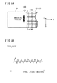
- the smoothing process will be described in detail below with reference to FIGS. 8A and 8B .
- FIG. 8A schematically shows expanded projection image data 122 within the projection region 98 (see FIG. 5B ).
- the projection image data 120 which form part of the expanded projection image data 122, are made up of a plurality of pixels 124.
- a two-dimensional matrix of pixels 124 is disposed within the detecting region 80.
- the smoothing processor 116 performs the smoothing process along the direction of the arrow (X-axis) on at least one image row within the detecting region 80 that lies adjacent to the non-detecting region 96.
- the smoothing process may be any of various known processes, e.g., a moving average process, a convolution process including a Gaussian filter, a statistical process including a median filter or a maximum value/minimum value filter, a morphological process, and an edge-preserving smoothing process.
- the smoothing processor 116 may perform the smoothing process on each image row, or on a plurality of image rows at a time.
- FIG. 8B shows pixel value profiles taken along line VIIIB-VIIIB of FIG. 8A . More specifically, the solid-line curve represents a pixel value profile produced before the smoothing process is carried out, and the broken-line curve represents a pixel value profile produced after the smoothing process is carried out. As can be seen from FIG. 8B , variations in the pixel values along the X-axis are reduced after the smoothing process is carried out.
- the values of the pixels 124 which are calculated by the smoothing process in step S7, are stored as temporary data, rather than being applied to update and overwrite the present projection image data. This is because the actual detected values of the pixels 124, which belong to the detecting region 80, should preferably be used for generating a tomographic image.
- step S8 the extrapolating processor 118 performs an extrapolating process on the temporary data, which was smoothed in step S7, along the prescribed direction (Y-axis). The extrapolating process will be described in detail below with reference to FIGS. 9A and 9B .
- FIG. 9A schematically shows expanded projection image data 122 within the projection region 98 (see FIG. 5B ).
- the expanded projection image data 122, the projection image data 120, and the detecting region 80 shown in FIG. 9A are identical to those shown in FIG. 8A and will not be described in detail below.
- a two-dimensional matrix of pixels 126 are disposed in the non-detecting region 96. For illustrative purposes, only one line of pixels 126 along the Y-axis is illustrated, whereas other pixels in the non-detecting region 96 are omitted from illustration.
- the extrapolating processor 118 performs an extrapolating process along the direction indicated by the arrow (Y-axis) on all of the pixels 126 belonging to the non-detecting region 96, thereby determining the values of the pixels 126.
- the extrapolating process may be any of various known extrapolating processes, e.g., a function approximating process such as a polygonal process or a nonlinear function process, a zeroth-order (replacement) extrapolating process, a first-order (linear) extrapolating process, and a third-order (cubic) extrapolating process.
- the range of pixels 124 used for the extrapolating process may be changed depending on the extrapolating process used. For example, one pixel is processed if the zeroth-order extrapolating process is employed, and two pixels are processed if the first-order extrapolating process is employed.
- FIG. 9B shows a pixel value profile taken along line IXB-IXB of FIG. 9A .
- a boundary line (boundary) 128 between the detecting region 80 (right-hand region) and the non-detecting region 96 (left-hand region) is represented by the broken line.
- the solid-line curve represents a pixel value profile produced in a case where values of the pixels 126 in the non-detecting region 96 are determined according to the zeroth-order extrapolating process.
- values of the pixels 126 belonging to image rows in the non-detecting region 96 i.e., values of the temporary data calculated in step S7) are identical.
- the extrapolating processor 118 preferably determines the values of the pixels 126 that are present within the non-detecting region 96 (and also within the same image rows) so as to be as uniform as possible. To meet such a demand, the extrapolating processor 118 preferably employs a low-order extrapolating process, such as the zeroth-order extrapolating process or the first-order extrapolating process. For the same reason, the differences ⁇ between values of the pixels 124 adjacent to the boundary line 128 and values of the pixels 126 adjacent to the boundary line 128 may be set so as to fall within a prescribed range. It has been confirmed that, with the values of the pixels 124, 126 being established in this manner, it is possible to generate an appropriate tomographic image independently of various combinations of body types of subjects 24, locations of regions of interests 94, and image capturing conditions.
- step S9 the backprojection processor 114 generates backprojection data for each image capturing process from the expanded projection image data 122 acquired in step S8.
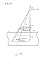
- a process of determining the value of a pixel 130 (see FIG. 10 ), which is present within the region of interest 94, will be described below with reference to FIG. 10 .
- the position at the coordinates A3 represents a point of intersection between the projection plane 82 and a straight line N interconnecting the pixel 130 and the position of the radiation source 20.
- the backprojection processor 114 adds the values of pixels 124, 126 (the values of backprojection data) corresponding to the coordinates A3 to the value of the pixel 130. If the coordinates A3 are present between the positions of the pixels 124 and 126, then the backprojection processor 114 may calculate the values of backprojection data according to a known interpolation process. In this manner, the same calculating process (backprojection process) is carried out on all of the pixels 130 that are present within the region of interest 94. Since the values of the pixels 126 in the non-detecting regions 95, 96 have been determined in advance, different calculations apart from the backprojection process, e.g., product-sum calculations for each pixel 126, are not necessary.
- step S10 the image reconstructor 16 judges whether or not the reconstruction of an image based on all the expanded projection image data 122 is completed. If the image reconstructor 16 determines that the reconstruction is not completed (S10: NO), then control returns to step S4 and steps S4 through S9 are repeated. In other words, the backprojection data generated from radiation 26 emitted from the radiation source 20 at different preset positions (angles) are successively added to gradually generate a tomographic image 142 (see FIGS. 11B through 12B ) as a complete image. If the image reconstructor 16 determines that the reconstruction is completed (S10: YES), then control proceeds to step S11.
- FIG. 11A shows a visualized tomographic image 136 obtained for a case in which the smoothing process is not performed.
- FIG. 11B shows a visualized tomographic image 142 obtained for a case in which the smoothing process is performed.
- steps S7 and S8 also are carried out on the non-detecting region 95 (see FIG. 5B ), which is not shown in FIGS. 8A and 9A , as well as the non-detecting region 96.
- the visualized tomographic image 136 which is obtained without the smoothing process being performed, includes image regions 138, 140, which correspond respectively to the non-detecting regions 95, 96, having striped density irregularities, i.e., so-called artifacts, therein that extend along the Y-axis.
- the visualized tomographic image 142 which is obtained with the smoothing process being performed, does not contain artifacts in any image regions thereof.
- the smoothing process is performed on the pixels 126 in the non-detecting regions 95, 96 along a direction, e.g., a direction that extends along the X-axis, perpendicular to a prescribed direction, e.g., a direction along the Y-axis, the expanded projection image data 122, as well as the tomographic image 142 generated with the expanded projection image data 122 added thereto, are prevented from suffering from artifacts.
- the smoothing process is particularly effective in the case that a tomographic image is generated according to a filter backprojection process.
- the extrapolating process determines values of the pixels 126 in the non-detecting regions 95, 96, regardless of whether or not any regions of the subject 24 actually are present in the expanded regions 90, 92. More specifically, if a region of the subject 24 is present within the designated region 33, and a region of the subject 24 is not present within the expanded regions 90, 92, then the energy of the image, i.e., the attenuation rate of radiation 26, may not be constant. If the energy of the image is not kept constant, then in the case that the tomographic image 142 is output as a negative image, the density corresponding to blank regions within the expanded regions 90, 92 may be reduced relatively to other regions thereof. In other words, the edge contrast of the density near the edge (contour line) of the subject 24 tends to be lowered.
- the term "blank regions" refers to image regions where radiation 26 is detected or can be detected without actually having passed through the subject 24.
- the tomographic image generator 104 may carry out a blackening process for bringing, to a prescribed constant value, values of plural pixels 130 that belong to a prescribed region existing within the region of interest 94, or more specifically, a prescribed region existing within the expanded regions 90, 92, which are external regions (blank regions) of the subject 24.
- image regions belonging to the blank regions can be identified using a known algorithm, such as a segmentation process or the like.
- the blackening process may be carried out on the generated tomographic image 142, or on each of the expanded projection image data 122.
- the tomographic image generator 104 performs a blackening process for bringing, to a prescribed constant value, values of plural pixels 126 that belong to a prescribed region existing within the projection region 98, or more specifically, a prescribed region existing within the non-detecting regions 95, 96, which are external regions (blank regions) of the subject 24.
- a blackening process on as few images as possible, i.e., a completed single tomographic image 142.
- step S7 an edge-preserving smoothing process may be performed on the projection image data 120.
- the edge-preserving smoothing process since the edge contrast of the density near the edge (contour line) of the subject 24 is lowered, reductions in image density within blank regions are minimized.
- the blackening process performed in this manner serves to increase the dazzle resistance at the time that the user sees the tomographic image 142, and hence increases the diagnostic capability of the image.
- the blackening process is particularly effective for cases in which mammographic images are output having a wide dynamic range of luminance.
- step S11 the mark position determiner 106 determines the positions of marks 144R, 144L (see FIG. 12A ) to be displayed together with the tomographic image 142 generated in steps S4 through S9. For example, the mark position determiner 106 calculates and determines the positions of boundary lines between the designated region 33 and the expanded regions 90, 92, based on positional information concerning the region of interest 94, which is supplied from the region-of-interest determiner 102.
- step S12 the tomographic image generating apparatus 10 displays the tomographic image 142 as a diagnostic image on the monitor 34.
- the monitor 34 displays a tomographic image 142 representing a chest section of the subject 24.
- the tomographic image 142 which does not contain artifacts therein as shown in FIG. 11B , is obtained by using the expanded projection image data 122, which are free of striped irregularities that extend along the Y-axis.
- the displayed tomographic image 142 includes a mark 144L on a left hand side thereof, which represents an open square bracket, and a mark 144R on a right hand side thereof, which represents a closed square bracket.
- the marks 144L, 144R when seen in combination, define a vertical range, which serves to notify the user of the location of the designated region 33 within the tomographic image 142.
- FIG. 12B shows a displayed tomographic image 146 of the region of interest 94 along a sectional plane 84 (see FIG. 4A ) at a different height.
- the displayed tomographic image 142 includes respective marks 148L, 148R on left and right hand sides thereof.
- the marks 148L, 148R jointly define a vertical range, which is smaller than the vertical range defined by the marks 144L, 144R shown in FIG. 12A .
- the designated region 33 displayed in the tomographic image 146 is smaller than the designated region 33 displayed in the tomographic image 142.
- the user is able to recognize that the sectional plane 84 (see FIG. 4A ) of the tomographic image 146 is positioned more in a positive direction along the Z-axis than the sectional plane 84 of the tomographic image 142.
- the marks 144L, 144R may be marks representative of a distribution of added numbers of pixels 124 that belong to the detecting region 80, from among the expanded projection image data 122 used to generate the tomographic image 142.
- the marks 144L, 144R which are displayed together with the tomographic image 142 shown in FIG. 12A , enable identification of the image region, which has used the values of the pixels 124 belonging to the detecting region 80, i.e., the values of the projection image data 120, in all the expanded projection image data 122 (at a proportion of 100%).
- the distribution of added numbers may be not only in two levels (100% or otherwise), but also in three or more levels (e.g., less than 50%, 50 through 75%, and 75% or more).
- the marks may be represented in any combination of characters, figures, patterns, hues, etc.
- the extrapolating process is performed on the acquired projection image data 120 along a prescribed direction (Y-axis) in order to generate a tomographic image 142 without the need for any special processing sequences. Since the smoothing process along a prescribed vertical direction (X-axis) also is performed in order to determine the values of the pixels 126 in the non-detecting regions 95, 96, it is possible to reduce striped density irregularities that extend along the Y-axis, which might otherwise be caused by the extrapolating process. Consequently, in a case where a tomographic image 142 including expanded regions is generated, the amount of processed data required to generate the tomographic image 142 is reduced, and artifacts are prevented from occurring in the tomographic image 142.
- the backprojection processor 114 digitally adds backprojection data from respective image capturing processes.
- electric charges may be successively accumulated (added in an analog fashion) in the storage capacitors 53 in the radiation detector 40 according to a plurality of successive image capturing processes.
Landscapes
- Physics & Mathematics (AREA)
- General Physics & Mathematics (AREA)
- Engineering & Computer Science (AREA)
- Theoretical Computer Science (AREA)
- Apparatus For Radiation Diagnosis (AREA)
Abstract
Description
- The present invention relates to an apparatus for and a method of generating a tomographic image.
- Recently, apparatus have been proposed in the medical field for irradiating an affected area in a subject such as a human body with radiation from a radiation source, which is moved to different positions to capture respective radiographic images of the affected area, and for processing the obtained projection image data into a desired tomographic image of the affected area for detailed observation of the affected area.
- Japanese Laid-Open Patent Publication No.
2004-121853 - There have also been proposed various processes for minimizing artifacts (false images) in tomographic images by improving a process of calculating partially sampled field-of-view data.
- Japanese Laid-Open Patent Publication No.
2005-152658 - Japanese Laid-Open Patent Publication No.
2008-200273 - However, the apparatus and methods disclosed in Japanese Laid-Open Patent Publication No.
2004-121853 2005-152658 2008-200273 - It is an object of the present invention to provide an apparatus for and a method of generating a tomographic image, which is representative of an expanded range, while reducing the amount of processed data required to generate the tomographic image, and minimizing artifacts produced in the tomographic image.
- According to the present invention, there is provided a tomographic image generating apparatus comprising a radiation source for applying radiation to a subject, a radiation detector for detecting radiation that has passed through the subject and acquiring projection image data from the detected radiation, and tomographic image generating means for generating a tomographic image in a region of interest disposed in the subject and interposed between the radiation source and the radiation detector, using a plurality of projection image data acquired by the radiation detector in image capturing processes, which are carried out while a relative positional relationship between the radiation source and the radiation detector successively changes. The tomographic image generating means includes a data determiner for performing an extrapolating process on each of the acquired projection image data along a prescribed direction, and for performing a smoothing process on each of the acquired projection image data along a direction perpendicular to the prescribed direction, thereby determining values of a plurality of pixels in non-detecting regions, which do not belong to a detecting region of the radiation detector, the determined values of the pixels also being used to generate the tomographic image.
- Since the extrapolating process is carried out on each of the acquired projection image data along the prescribed direction, the tomographic image can be generated without the need for special processing sequences. Since the smoothing process is performed along the direction perpendicular to the prescribed direction in order to determine the values of the pixels in the non-detecting regions, it is possible to reduce striped density irregularities that extend along the prescribed direction, which might otherwise be caused by the extrapolating process. Consequently, in a case where a tomographic image including expanded regions is generated, the amount of processed data required to generate the tomographic image can be reduced, and artifacts can be prevented from occurring in the tomographic image.
- The prescribed direction preferably comprises a direction projected onto a projection plane including the detecting region, and extending parallel to a direction of relative motion of the radiation source.
- The tomographic image generating means preferably further includes a projection region determiner for determining a projection region on the projection plane, onto which the radiation source projects the region of interest, based on information concerning the position of the region of interest and the relative positional relationship. The data determiner preferably determines values of a plurality of pixels in non-detecting regions, which belong to the projection region determined by the projection region determiner, and which do not belong to the detecting region.
- The projection region determiner preferably determines a projection region of one size irrespective of the relative positional relationship.
- The tomographic image generating means preferably further includes a data corrector for correcting a spectral intensity at each spatial frequency of the projection image data that exhibits geometric unsharpness due to the image capturing processes.
- The data corrector preferably corrects the projection image data before the data determiner determines the values of the pixels in the non-detecting regions.
- The data determiner preferably determines the values of the pixels in the non-detecting regions such that differences between the values of pixels adjacent to boundaries between the detecting region and the non-detecting regions fall within a prescribed range.
- The data determiner preferably performs a zeroth-order extrapolating process or a first-order extrapolating process to thereby determine the values of the pixels in the non-detecting regions.
- The tomographic image generating means preferably performs a blackening process on the tomographic image for bringing to a prescribed constant value the values of plural pixels that belong to a prescribed region existing within the region of interest.
- The data determiner preferably determines the values of the pixels in the non-detecting regions by performing the extrapolating process on a plurality of pixels in the detecting region, based on values produced by the smoothing process performed along the direction perpendicular to the prescribed direction.
- The data determiner preferably determines the values of the pixels in the non-detecting regions by performing the smoothing process along the direction perpendicular to the prescribed direction on a plurality of pixels in the non-detecting regions, the values of which are temporarily determined by the extrapolating process, after the extrapolating process has been performed.
- The tomographic image generating apparatus preferably further comprises a display unit for displaying marks indicative of a distribution of added numbers of pixels belonging to the detecting region and which are used to generate the tomographic image, the marks being displayed in overlapping relation to the tomographic image generated by the tomographic image generating means.
- According to the present invention, there also is provided a method of generating a tomographic image of a subject using a radiation source for applying radiation to the subject, and a radiation detector for detecting radiation that has passed through the subject and acquiring projection image data from the detected radiation, and by carrying out image capturing processes while a relative positional relationship between the radiation source and the radiation detector successively changes, comprising the steps of acquiring a plurality of projection image data through the radiation detector, and performing an extrapolating process on each of the acquired projection image data along a prescribed direction, and performing a smoothing process on each of the acquired projection image data along a direction perpendicular to the prescribed direction, thereby determining values of a plurality of pixels in non-detecting regions, which do not belong to a detecting region of the radiation detector, the determined values of the pixels also being used to generate the tomographic image.
- With the tomographic image generating apparatus and the tomographic image generating method according to the present invention, an extrapolating process is performed on the acquired projection image data along the prescribed direction in order to generate a tomographic image without the need for any special processing sequences. Further, since a smoothing process along the direction perpendicular to the prescribed direction also is performed in order to determine values of the pixels in the non-detecting regions, it is possible to reduce striped density irregularities that extend along the prescribed direction, which might otherwise be caused by the extrapolating process. Consequently, in a case where a tomographic image including expanded regions is generated, the amount of processed data required to generate the tomographic image is reduced, and artifacts are prevented from occurring in the tomographic image.
- The above and other objects, features, and advantages of the present invention will become more apparent from the following description when taken in conjunction with the accompanying drawings in which preferred embodiments of the present invention are shown by way of illustrative example.
-
-
FIG. 1 is a schematic view, partially in block form, of a tomographic image generating apparatus according to an embodiment of the present invention; -
FIG. 2 is a circuit diagram, partially in block form, of a radiation detector in the tomographic image generating apparatus shown inFIG. 1 ; -
FIG. 3A is a side elevational view illustrative of a radiographic image capturing process, in which a radiation source is displaced to a frontal position; -
FIG. 3B is a fragmentary view illustrating the concepts of a detecting region of the radiation detector and a projection plane; -
FIG. 4A is a side elevational view illustrative of a tomosynthetic image capturing process upon initiation of the process; -
FIG. 4B is a side elevational view illustrative of the tomosynthetic image capturing process upon termination of the process; -
FIGS. 5A and 5B are views illustrating the concepts of a region of interest, a projection region, a detecting region, and non-detecting regions; -
FIG. 6 is a detailed functional block diagram of an image reconstructor shown inFIG. 1 ; -
FIG. 7 is a flowchart of an operation sequence of the tomographic image generating apparatus shown inFIG. 1 ; -
FIGS. 8A and 8B are diagrams showing a specific example of a smoothing process performed in step S7 shown inFIG. 7 ; -
FIGS. 9A and 9B are diagrams showing a specific example of an extrapolating process performed in step S8 shown inFIG. 7 ; -
FIG. 10 is a diagram showing a specific example of a backprojection process performed in step S9 shown inFIG. 7 ; -
FIG. 11A is a view of a visualized tomographic image obtained if the smoothing process is not performed; -
FIG. 11B is a view of a visualized tomographic image obtained if the smoothing process is performed; and -
FIGS. 12A and 12B are views of specific examples of tomographic images displayed in step S12 shown inFIG. 7 . - A tomographic image generating method according to a preferred embodiment of the present invention in relation to a tomographic image generating apparatus that carries out the tomographic image generating method will be described in detail below with reference to the accompanying drawings.
- As shown in
FIG. 1 , a tomographicimage generating apparatus 10 according to an embodiment of the present invention basically includes aradiation detecting device 12, a projection imagedata acquiring assembly 14, animage reconstructor 16, and aconsole 18 for controlling theradiation detecting device 12, the projection imagedata acquiring assembly 14, and theimage reconstructor 16. - The projection image
data acquiring assembly 14 includes aradiation source 20 disposed in confronting relation to theradiation detecting device 12, amoving mechanism 22 for moving theradiation source 20 successively to a plurality of preset positions, aradiation controller 28 for controlling theradiation source 20 to applyradiation 26 to asubject 24 over theradiation detecting device 12 at times coincident with theradiation source 20 reaching each of the preset positions, and animage storage unit 32 for storing in an image memory 30 a plurality of projection image data sent successively from theradiation detecting device 12. - The
image reconstructor 16 processes the plural projection image data stored in theimage memory 30 in order to generate or reconstruct a tomographic image including a certain region 33 (hereinafter referred to as a "designatedregion 33") of thesubject 24. Theimage reconstructor 16 supplies image data representing the tomographic image to a monitor 34 (display unit) for displaying the tomographic image. - As shown in
FIGS. 1 and2 , theradiation detecting device 12 includes acasing 36, a battery 38 (seeFIG. 2 ) housed in thecasing 36, aradiation detector 40 housed in thecasing 36, and adetector controller 42 housed in thecasing 36. - As shown in
FIG. 2 , theradiation detector 40 comprises an array of thin-film transistors (TFTs) 52 arranged in rows and columns, aphotoelectric conversion layer 51 made of a material such as amorphous selenium (a-Se) for generating electric charges upon detection ofradiation 26, thephotoelectric conversion layer 51 being disposed on the array ofTFTs 52, and an array ofstorage capacitors 53 connected to thephotoelectric conversion layer 51. Upon application ofradiation 26 to theradiation detector 40, thephotoelectric conversion layer 51 generates electric charges, and thestorage capacitors 53 store the generated electric charges. Then, theTFTs 52 are turned on along each row at a time to read the electric charges from thestorage capacitors 53 as an image signal. InFIG. 2 , thephotoelectric conversion layer 51 and one of thestorage capacitors 53 are shown as apixel 50, thepixel 50 being connected to one of theTFTs 52. Details of theother pixels 50 are omitted from illustration. Since amorphous selenium tends to change in structure and lose functions thereof at high temperatures, amorphous selenium needs to be used within a certain temperature range. Therefore, some means for cooling theradiation detector 40 should preferably be provided in thecasing 36. - The
TFTs 52, which are connected to therespective pixels 50, are connected torespective gate lines 54 extending parallel to the rows, and torespective signal lines 56 extending parallel to the columns. The gate lines 54 are connected to aline scanning driver 58, and thesignal lines 56 are connected to amultiplexer 66 that serves as a reading circuit. - The gate lines 54 are supplied with control signals Von, Voff for turning on and off the
TFTs 52 along the rows from theline scanning driver 58. Theline scanning driver 58 comprises a plurality of first switches SW1 for switching between the gate lines 54, and anaddress decoder 60 for outputting a selection signal for selecting one of the first switches SW1 at a time. Theaddress decoder 60 is supplied with an address signal from thedetector controller 42. - The signal lines 56 are supplied with electric charges stored in the
storage capacitors 53 of thepixels 50 through theTFTs 52 arranged in the columns. The electric charges supplied to thesignal lines 56 are amplified byamplifiers 62, which are connected respectively to the signal lines 56. Theamplifiers 62 are connected through respective sample and holdcircuits 64 to themultiplexer 66. Themultiplexer 66 comprises a plurality of second switches SW2 for successively switching between the signal lines 56, and anaddress decoder 68 for outputting a selection signal for selecting one of the second switches SW2 at a time. Theaddress decoder 68 is supplied with an address signal from thedetector controller 42. Themultiplexer 66 has an output terminal connected to an A/D converter 70. An image signal generated by themultiplexer 66 based on electric charges from the sample and holdcircuits 64 is converted by the A/D converter 70 into a digital image signal (projection image data), which is supplied to thedetector controller 42. Thedetector controller 42 supplies the projection image data to the image memory 30 (seeFIG. 1 ), which stores the supplied projection image data. In summary, each time that the tomographicimage generating apparatus 10 operates to perform a radiographic image capturing process, theradiation detecting device 12 outputs projection image data. Projection image data successively output from theradiation detecting device 12 are stored in theimage memory 30 in chronological order, for example. - The projection image
data acquiring assembly 14 moves theradiation source 20 disposed in facing relation to theradiation detecting device 12 successively to a plurality of different positions. Each time that theradiation source 20 reaches one of the positions, theradiation source 20 appliesradiation 26 to the subject 24 over theradiation detecting device 12, which detectsradiation 26 that has passed through the subject 24, and generates projection image data of the subject 24 data based on the detectedradiation 26. Therefore, as theradiation source 20 moves successively through the respective positions, theradiation source 20 appliesradiation 26 to the subject 24 at different angles or in different directions, and theradiation detecting device 12 generates a plurality of projection image data of the subject 24. - The tomographic
image generating apparatus 10 according to the illustrated embodiment includes theradiation source 20, which is movable with respect to theradiation detector 40 that is fixed in place. However, at least one of theradiation source 20 and theradiation detector 40 may be moved in order to capture a plurality of projection image data of the subject 24 at different angles. InFIG. 1 , theradiation source 20 is shown as being moved and placed in three different positions, which are spaced along the longitudinal axis of the subject 24. However, theradiation source 20 may be moved and placed in two different positions, or in four or more different positions. InFIG. 1 , theradiation source 20 is moved along a straight path interconnecting the different positions. However, theradiation source 20 may be moved along a curved path such as an arcuate path that interconnects the different positions. - For facilitating understanding of the present invention, certain terms used in the description of the present invention will be explained with reference to
FIGS. 3A through 5B . It is assumed herein that theradiation detector 40 is fixed in position at all times. Image capturing processes referred to in the present invention include an individual image capturing process, which is carried out at a time when theradiation source 20 has reached each of the preset positions, and a collective image capturing process, which collectively represents a plurality of individual image capturing processes. Each individual image capturing process will be referred to as a "radiographic image capturing process", and the collective image capturing process, which collectively represents a plurality of individual image capturing processes, will be referred to as a "tomosynthetic image capturing process". -
FIG. 3A illustrates a radiographic image capturing process (a so-called scout image capturing process) with theradiation source 20 displaced to a frontal position. In -
FIG. 3A , the designatedregion 33 in the subject 24 corresponds to a sectional region of a radiation field RF at a certain height (Z-axis position). InFIG. 3A and other relevant figures, the Z-axis extends vertically perpendicular to the longitudinal axis of the subject 24 who lies horizontally over theradiation detecting device 12, the Y-axis extends along the longitudinal axis of the subject 24, and the X-axis extends horizontally transverse to the longitudinal axis of the subject 24 and perpendicular to the Z-axis and the Y-axis. The designatedregion 33 comprises a planar region which lies substantially parallel to a flat region (hereinafter referred to as a "detectingregion 80") where the pixels 50 (seeFIG. 2 ) of theradiation detector 40 reside. With the designatedregion 33 being established at a certain position in the subject 24, a desired tomographic image of the designatedregion 33 is generated. The designatedregion 33 lies within a sectional plane 84 (seeFIG. 4A ) in the subject 24. The designatedregion 33 becomes progressively smaller as thesectional plane 84 is shifted in a positive direction (upward direction) along the Z-axis. For illustrative purposes, the designatedregion 33 as well as later-described expanded regions 90, 92 (seeFIG. 5A ) are illustrated as having a thickness along the Z-axis. - As shown in
FIG. 3B , aprojection plane 82 is defined in common to projection image data that is used to generate a tomographic image. Theprojection plane 82 may be defined as a plane including the detectingregion 80 of theradiation detector 40. In other words, theprojection plane 82 is a plane onto which the projection image data are projected, or onto which the projection image data preferably are projected for processing purposes. In the present embodiment, the detectingregion 80 is flat and theprojection plane 82 also is flat. However, the detectingregion 80 may be curved, and theprojection plane 82 may be defined as including a curved detectingregion 80. - If the
radiation source 20 is moved to other positions apart from the frontal position shown inFIG. 3A and image capturing processes are carried out with theradiation source 20 in such other positions, the radiation field RF may not cover the designatedregion 33 in its entirety during the image capturing processes. Stated otherwise, the designatedregion 33 may include a partial region, which cannot be backprojected with the projection image data obtained by the image capturing processes. However, if image regions, i.e., projection regions, are expanded by making up for a shortage of the projection image data, then even though the partial region cannot be backprojected, backprojection image data can be calculated therefor. By using in combination the projection image data that actually are detected by theradiation detector 40 and virtual projection image data that are not actually detected by theradiation detector 40, it is possible to expand a region of interest 94 (seeFIG. 5A ) for which a tomographic image is to be generated for the benefit of the user (a doctor or radiological technician) in diagnostic practice. A process of determining the region ofinterest 94 in relation to a maximum size thereof will be described with reference toFIGS. 4A through 5B . - As shown in
FIG. 4A , at the start of a tomosynthetic image capturing process, theradiation source 20, which is located in one of the positions other than the frontal position, makes a projection, i.e., appliesradiation 26 to the detectingregion 80, thereby creating a radiation field RF1. At this time, theradiation source 20 is displaced in a positive direction along the Y-axis, and hence the radiation field RF1 also is displaced in the positive direction along the Y-axis, compared with the radiation field RF (seeFIG. 3 ) at the time that theradiation source 20 is in the frontal position. A line of intersection between thesectional plane 84, which includes the designatedregion 33 and the radiation field RF1, will be referred to as a "boundary line 86". - As shown in
FIG. 4B , at the end of the tomosynthetic image capturing process, theradiation source 20, which is located in another one of the positions other than the frontal position, makes a projection, i.e., appliesradiation 26 to the detectingregion 80, thereby creating a radiation field RF2. At this time, theradiation source 20 is displaced in a negative direction along the Y-axis, and hence the radiation field RF2 also is displaced in the negative direction along the Y-axis, compared with the radiation field RF (seeFIG. 3 ) at the time that theradiation source 20 is in the frontal position. A line of intersection between thesectional plane 84, which includes the designatedregion 33 and the radiation field RF2, will be referred to as a "boundary line 88". Theboundary line 86 shown inFIG. 4A and theboundary line 88 shown inFIG. 4B represent line segments extending along the X-axis. - For generating a tomographic image using at least one of the projection image data that actually are detected by the
radiation detector 40, a region ofinterest 94, opposite sides of which are defined by theboundary lines FIG. 5A , the region ofinterest 94 corresponds to the sum of the designatedregion 33 and the expandedregions 90, 92. - As shown in
FIGS. 5A and 5B , the expanded region 90 is a planar region, opposite sides of which are defined by a side of the designatedregion 33 facing in the positive direction of the Y-axis and theboundary line 86, and the expandedregion 92 is a planar region, opposite sides of which are defined by a side of the designatedregion 33 facing in the negative direction of the Y-axis and theboundary line 88. Theradiation detector 40 includesnon-detecting regions projection plane 82, which do not belong to the detectingregion 80, and which are created by theradiation source 20 projecting the respective expandedregions 90, 92 onto theprojection plane 82 in respective virtual radiation fields VRF. In other words, theradiation detector 40 projects the region ofinterest 94 onto theprojection plane 82, thereby creating a projection region 98 (seeFIG. 5B ), which is representative of the combination of the detectingregion 80 and thenon-detecting regions - Since the region of
interest 94 including the designatedregion 33 lies parallel to theprojection plane 82, theprojection region 98 is similar in shape to the region ofinterest 94. In the illustrated embodiment, the region ofinterest 94, as well as theprojection region 98, are of a rectangular shape. -
FIG. 6 is a detailed functional block diagram of theimage reconstructor 16 shown inFIG. 1 . - As shown in
FIG. 6 , theimage reconstructor 16 includes adata input section 100 for entering projection image data, etc., from theimage memory 30, a region-of-interest determiner 102 for determining a region ofinterest 94 based on image capturing conditions (e.g., positional information of the designatedregion 33, theradiation source 20, etc.) supplied from theconsole 18, a tomographic image generator 104 (tomographic image generating means) for generating a tomographic image within the region ofinterest 94 based on projection image data entered from thedata input section 100 and the position of the region ofinterest 94, which is determined by the region-of-interest determiner 102, and amark position determiner 106 for determining positions of marks that are representative of the position of the designatedregion 33, for example. - The
tomographic image generator 104 includes aprojection region determiner 108 for determining arespective projection region 98 for each radiographic image capturing process (or tomosynthetic image capturing process), adata corrector 110 for correcting the spectral intensity at each spatial frequency of the projection image data (image data) that exhibits geometric unsharpness due to the image capturing processes, adata determiner 112 for determining values of a plurality of pixels in thenon-detecting regions backprojection processor 114 for performing a backprojection process on the projection image data (hereinafter also referred to as "expanded projection image data") on which the extrapolating process and smoothing process have been performed by thedata determiner 112. - The
data determiner 112 includes a smoothingprocessor 116 for performing a smoothing process on the projection image data along a direction, e.g., a direction that extends along the X-axis, perpendicular to a prescribed direction, e.g., a direction along the Y-axis, and an extrapolatingprocessor 118 for performing an extrapolation process on the projection image data along the certain direction. - The tomographic
image generating apparatus 10 according to the present embodiment is basically constructed as described above. An operation sequence of the tomographicimage generating apparatus 10 will be described in detail below with reference toFIGS. 1 through 6 and the flowchart shown inFIG. 7 . - In step S1 shown in
FIG. 7 , theconsole 18 determines a designatedregion 33 in a tomosynthetic image capturing process according to an instruction from the user (a doctor or radiological technician). For example, the user determines the range of the designated region 33 (positions along the X-axis and the Y-axis) and/or the height of the designated region 33 (a position along the Z-axis) based on an interpretation of a radiographic image produced in a radiographic image capturing process, e.g., the scout radiographic image capturing process shown inFIG. 3A , which has already been carried out. - In step S2, the region-of-
interest determiner 102 determines a region ofinterest 94 as a target region for which a tomographic image is to be generated. More specifically, the region-of-interest determiner 102 first acquires positional information from theconsole 18 concerning the designatedregion 33, theradiation source 20, theradiation detector 40, etc. Then, the region-of-interest determiner 102 determines expandedregions 90, 92 based on image capturing conditions shown inFIG. 4A (maximum Y-axis positions) andFIG. 4B (minimum Y-axis positions). The image capturing conditions include, for example, the distance between theradiation source 20 and the subject 24, the distance between theradiation source 20 and the casing 36 (radiation detector 40), the size of theradiation detector 40, etc. InFIG. 5A , the expandedregions 90, 92 are determined in order to maximize the size of the region ofinterest 94. However, the expandedregions 90, 92 may be determined in order to make the size of the region ofinterest 94 smaller than as illustrated. - Thereafter, the region-of-
interest determiner 102 supplies positional information concerning the determined region ofinterest 94 to thetomographic image generator 104. - In step S3, the tomographic
image generating apparatus 10 initiates a tomosynthetic image capturing process. The projection imagedata acquiring assembly 14 moves theradiation source 20 disposed in facing relation to theradiation detecting device 12 successively to the preset positions, and controls theradiation source 20 at the preset positions in order to applyradiation 26 to the subject 24 from respective different directions over theradiation detecting device 12, so as to produce a plurality of projection image data. Then, the projection imagedata acquiring assembly 14 outputs the projection image data, which are temporarily stored in theimage memory 30. The projection imagedata acquiring assembly 14 may acquire projection image data in synchronism with, or independently and out of synchronism with, the execution of a backprojection process (step S9), to be described later. If such processes are carried out in synchronism with each other, then the storage capacity of theimage memory 30, which serves as a buffer memory, can be reduced. - In step S4, the
data input section 100 enters projection image data 120 (seeFIG. 8A , for example) acquired in the tomosynthetic image capturing process. Thedata input section 100 may enterprojection image data 120 according to the order in which the data are acquired or captured. If thedata input section 100 entersprojection image data 120 at the same time, thedata input section 100 may also enter identification information thereof, which is associated with the order in which theprojection image data 120 are captured. Thedata input section 100 also enters information (hereinafter referred to as "imaging position information") concerning the relative positional relationship between theradiation source 20 and theradiation detector 40 at the time that theprojection image data 120 are acquired. - In step S5, the
projection region determiner 108 determines aprojection region 98 for a present image capturing process, based on the positional information of the region ofinterest 94 determined in step S2, and the imaging position information entered in step S5. In the present embodiment, theprojection region determiner 108 determines aprojection region 98 of only one size, irrespective of the positions of theradiation source 20 and theradiation detector 40. In order to reduce the storage capacity required to store theprojection image data 120, theprojection region determiner 108 may determine a projection region of minimum size, which will be used in the backprojection process (step S9), to be described later. - In step S6, the
data corrector 110 corrects theprojection image data 120 that was entered in step S4. Theprojection image data 120, which are produced fromradiation 26 emitted from theradiation source 20, exhibit geometric unsharpness, i.e., image blurring, due to the image capturing processes. If the backprojection process is carried out directly on theprojection image data 120 exhibiting such geometric unsharpness, then a tomographic image generated from the backprojection process tends to be significantly reduced in spectral intensity within a high spatial frequency band. Accordingly, thedata corrector 110 corrects theprojection image data 120 for the spectral intensity in the high spatial frequency band. Although the degree of correction varies depending on how the image capturing process was carried out, thedata corrector 110 generally corrects theprojection image data 120 in a manner that reduces spectral intensity in a low spatial frequency band, while enhancing spectral intensity in a high spatial frequency band. The spectral intensity may be corrected according to a convolution process in real space with length used as a unit (masking process), or a multiplexing process in a Fourier space with a reciprocal of the length used as a unit (filtering process). - A backprojection process, which is carried out after step S6, is referred to as a filter backprojection process. If a simple backprojection process including a shift-and-add process is employed, then the process of step S6 is not required.
- As shown in
FIG. 5B , the unsharpness referred to above occurs along the direction in which a projectedimage 99, which is projected on theprojection plane 82 including thedetection region 80, of theradiation source 20 moves relatively, the direction corresponding to a prescribed direction along which an extrapolating process, to be described later, is carried out. In the illustrated embodiment, thedata corrector 110 corrects theprojection image data 120 for each image row (linearly) along the Y-axis. As a result, it should be noted that differences between adjacent pixels along the X-axis are relatively increased, which tends to impair the smoothness of a gradation image along the X-axis. - In step S7, the smoothing
processor 116 performs a smoothing process on theprojection image data 120, which was corrected in step S6, along a direction that extends along the X-axis, perpendicular to a prescribed direction, e.g., along the Y-axis. The smoothing process will be described in detail below with reference toFIGS. 8A and 8B . -
FIG. 8A schematically shows expandedprojection image data 122 within the projection region 98 (seeFIG. 5B ). Theprojection image data 120, which form part of the expandedprojection image data 122, are made up of a plurality ofpixels 124. In other words, a two-dimensional matrix ofpixels 124 is disposed within the detectingregion 80. For illustrative purposes, a plurality of pixels, which are present in thenon-detecting region 96, are omitted from illustration. - The smoothing
processor 116 performs the smoothing process along the direction of the arrow (X-axis) on at least one image row within the detectingregion 80 that lies adjacent to thenon-detecting region 96. The smoothing process may be any of various known processes, e.g., a moving average process, a convolution process including a Gaussian filter, a statistical process including a median filter or a maximum value/minimum value filter, a morphological process, and an edge-preserving smoothing process. The smoothingprocessor 116 may perform the smoothing process on each image row, or on a plurality of image rows at a time. -
FIG. 8B shows pixel value profiles taken along line VIIIB-VIIIB ofFIG. 8A . More specifically, the solid-line curve represents a pixel value profile produced before the smoothing process is carried out, and the broken-line curve represents a pixel value profile produced after the smoothing process is carried out. As can be seen fromFIG. 8B , variations in the pixel values along the X-axis are reduced after the smoothing process is carried out. - The values of the
pixels 124, which are calculated by the smoothing process in step S7, are stored as temporary data, rather than being applied to update and overwrite the present projection image data. This is because the actual detected values of thepixels 124, which belong to the detectingregion 80, should preferably be used for generating a tomographic image. - In step S8, the extrapolating
processor 118 performs an extrapolating process on the temporary data, which was smoothed in step S7, along the prescribed direction (Y-axis). The extrapolating process will be described in detail below with reference toFIGS. 9A and 9B . -
FIG. 9A schematically shows expandedprojection image data 122 within the projection region 98 (seeFIG. 5B ). The expandedprojection image data 122, theprojection image data 120, and the detectingregion 80 shown inFIG. 9A are identical to those shown inFIG. 8A and will not be described in detail below. A two-dimensional matrix ofpixels 126 are disposed in thenon-detecting region 96. For illustrative purposes, only one line ofpixels 126 along the Y-axis is illustrated, whereas other pixels in thenon-detecting region 96 are omitted from illustration. - The extrapolating
processor 118 performs an extrapolating process along the direction indicated by the arrow (Y-axis) on all of thepixels 126 belonging to thenon-detecting region 96, thereby determining the values of thepixels 126. The extrapolating process may be any of various known extrapolating processes, e.g., a function approximating process such as a polygonal process or a nonlinear function process, a zeroth-order (replacement) extrapolating process, a first-order (linear) extrapolating process, and a third-order (cubic) extrapolating process. The range ofpixels 124 used for the extrapolating process may be changed depending on the extrapolating process used. For example, one pixel is processed if the zeroth-order extrapolating process is employed, and two pixels are processed if the first-order extrapolating process is employed. -
FIG. 9B shows a pixel value profile taken along line IXB-IXB ofFIG. 9A . A boundary line (boundary) 128 between the detecting region 80 (right-hand region) and the non-detecting region 96 (left-hand region) is represented by the broken line. The solid-line curve represents a pixel value profile produced in a case where values of thepixels 126 in thenon-detecting region 96 are determined according to the zeroth-order extrapolating process. As can be understood fromFIG. 9B , values of thepixels 126 belonging to image rows in the non-detecting region 96 (i.e., values of the temporary data calculated in step S7) are identical. - For preventing artifacts from occurring, the extrapolating
processor 118 preferably determines the values of thepixels 126 that are present within the non-detecting region 96 (and also within the same image rows) so as to be as uniform as possible. To meet such a demand, the extrapolatingprocessor 118 preferably employs a low-order extrapolating process, such as the zeroth-order extrapolating process or the first-order extrapolating process. For the same reason, the differences Δ between values of thepixels 124 adjacent to theboundary line 128 and values of thepixels 126 adjacent to theboundary line 128 may be set so as to fall within a prescribed range. It has been confirmed that, with the values of thepixels subjects 24, locations of regions ofinterests 94, and image capturing conditions. - In step S9, the
backprojection processor 114 generates backprojection data for each image capturing process from the expandedprojection image data 122 acquired in step S8. A process of determining the value of a pixel 130 (seeFIG. 10 ), which is present within the region ofinterest 94, will be described below with reference toFIG. 10 . - As shown in
FIG. 10 , it is assumed that the coordinates corresponding to the position of thepixel 130 are indicated by A1 (Xt, Yt, Zt), and the coordinates corresponding to the position of theradiation source 20 are indicated by A2 (Xs, Ys, Zs). It is also assumed that theprojection plane 82 is set to Z = Zp (known value) parallel to the X-Y plane. - Among the positions, i.e., the coordinates A3 (Xp, Yp, Zp) on the
projection region 98 onto which theradiation source 20 projects thepixel 130, the values Xp, Yp thereof, which are not already known, are calculated according to simple geometric observations by the following equations:

- The position at the coordinates A3 represents a point of intersection between the
projection plane 82 and a straight line N interconnecting thepixel 130 and the position of theradiation source 20. Thebackprojection processor 114 adds the values ofpixels 124, 126 (the values of backprojection data) corresponding to the coordinates A3 to the value of thepixel 130. If the coordinates A3 are present between the positions of thepixels backprojection processor 114 may calculate the values of backprojection data according to a known interpolation process. In this manner, the same calculating process (backprojection process) is carried out on all of thepixels 130 that are present within the region ofinterest 94. Since the values of thepixels 126 in thenon-detecting regions pixel 126, are not necessary. - In step S10, the
image reconstructor 16 judges whether or not the reconstruction of an image based on all the expandedprojection image data 122 is completed. If theimage reconstructor 16 determines that the reconstruction is not completed (S10: NO), then control returns to step S4 and steps S4 through S9 are repeated. In other words, the backprojection data generated fromradiation 26 emitted from theradiation source 20 at different preset positions (angles) are successively added to gradually generate a tomographic image 142 (seeFIGS. 11B through 12B ) as a complete image. If theimage reconstructor 16 determines that the reconstruction is completed (S10: YES), then control proceeds to step S11. - Advantages of the smoothing process (step S7) will be described below with reference to
FIGS. 11A and 11B. FIG. 11A shows a visualizedtomographic image 136 obtained for a case in which the smoothing process is not performed.FIG. 11B shows a visualizedtomographic image 142 obtained for a case in which the smoothing process is performed. During generation of the visualizedtomographic image 142, steps S7 and S8 also are carried out on the non-detecting region 95 (seeFIG. 5B ), which is not shown inFIGS. 8A and9A , as well as thenon-detecting region 96. - As shown in
FIG. 11A , the visualizedtomographic image 136, which is obtained without the smoothing process being performed, includesimage regions non-detecting regions FIG. 11B , the visualizedtomographic image 142, which is obtained with the smoothing process being performed, does not contain artifacts in any image regions thereof. Therefore, if the smoothing process is performed on thepixels 126 in thenon-detecting regions projection image data 122, as well as thetomographic image 142 generated with the expandedprojection image data 122 added thereto, are prevented from suffering from artifacts. The smoothing process is particularly effective in the case that a tomographic image is generated according to a filter backprojection process. - The extrapolating process according to the present invention determines values of the
pixels 126 in thenon-detecting regions regions 90, 92. More specifically, if a region of the subject 24 is present within the designatedregion 33, and a region of the subject 24 is not present within the expandedregions 90, 92, then the energy of the image, i.e., the attenuation rate ofradiation 26, may not be constant. If the energy of the image is not kept constant, then in the case that thetomographic image 142 is output as a negative image, the density corresponding to blank regions within the expandedregions 90, 92 may be reduced relatively to other regions thereof. In other words, the edge contrast of the density near the edge (contour line) of the subject 24 tends to be lowered. The term "blank regions" refers to image regions whereradiation 26 is detected or can be detected without actually having passed through the subject 24. - The
tomographic image generator 104, e.g., thedata corrector 110, may carry out a blackening process for bringing, to a prescribed constant value, values ofplural pixels 130 that belong to a prescribed region existing within the region ofinterest 94, or more specifically, a prescribed region existing within the expandedregions 90, 92, which are external regions (blank regions) of the subject 24. For example, image regions belonging to the blank regions can be identified using a known algorithm, such as a segmentation process or the like. - The blackening process may be carried out on the generated
tomographic image 142, or on each of the expandedprojection image data 122. In this case, thetomographic image generator 104 performs a blackening process for bringing, to a prescribed constant value, values ofplural pixels 126 that belong to a prescribed region existing within theprojection region 98, or more specifically, a prescribed region existing within thenon-detecting regions tomographic image 142. - In step S7 (smoothing process), an edge-preserving smoothing process may be performed on the
projection image data 120. According to the edge-preserving smoothing process, since the edge contrast of the density near the edge (contour line) of the subject 24 is lowered, reductions in image density within blank regions are minimized. - The blackening process performed in this manner serves to increase the dazzle resistance at the time that the user sees the
tomographic image 142, and hence increases the diagnostic capability of the image. The blackening process is particularly effective for cases in which mammographic images are output having a wide dynamic range of luminance. - In step S11, the
mark position determiner 106 determines the positions ofmarks FIG. 12A ) to be displayed together with thetomographic image 142 generated in steps S4 through S9. For example, themark position determiner 106 calculates and determines the positions of boundary lines between the designatedregion 33 and the expandedregions 90, 92, based on positional information concerning the region ofinterest 94, which is supplied from the region-of-interest determiner 102. - In step S12, the tomographic
image generating apparatus 10 displays thetomographic image 142 as a diagnostic image on themonitor 34. - As shown in
FIG. 12A , themonitor 34 displays atomographic image 142 representing a chest section of the subject 24. Thetomographic image 142, which does not contain artifacts therein as shown inFIG. 11B , is obtained by using the expandedprojection image data 122, which are free of striped irregularities that extend along the Y-axis. - As shown in
FIG. 12A , the displayedtomographic image 142 includes amark 144L on a left hand side thereof, which represents an open square bracket, and amark 144R on a right hand side thereof, which represents a closed square bracket. Themarks region 33 within thetomographic image 142. -
FIG. 12B shows a displayedtomographic image 146 of the region ofinterest 94 along a sectional plane 84 (seeFIG. 4A ) at a different height. The displayedtomographic image 142 includesrespective marks marks marks FIG. 12A . In other words, the designatedregion 33 displayed in thetomographic image 146 is smaller than the designatedregion 33 displayed in thetomographic image 142. Thus, the user is able to recognize that the sectional plane 84 (seeFIG. 4A ) of thetomographic image 146 is positioned more in a positive direction along the Z-axis than thesectional plane 84 of thetomographic image 142. - Alternatively, the
marks pixels 124 that belong to the detectingregion 80, from among the expandedprojection image data 122 used to generate thetomographic image 142. - For example, the
marks tomographic image 142 shown inFIG. 12A , enable identification of the image region, which has used the values of thepixels 124 belonging to the detectingregion 80, i.e., the values of theprojection image data 120, in all the expanded projection image data 122 (at a proportion of 100%). The distribution of added numbers may be not only in two levels (100% or otherwise), but also in three or more levels (e.g., less than 50%, 50 through 75%, and 75% or more). The marks may be represented in any combination of characters, figures, patterns, hues, etc. - As described above, the extrapolating process is performed on the acquired
projection image data 120 along a prescribed direction (Y-axis) in order to generate atomographic image 142 without the need for any special processing sequences. Since the smoothing process along a prescribed vertical direction (X-axis) also is performed in order to determine the values of thepixels 126 in thenon-detecting regions tomographic image 142 including expanded regions is generated, the amount of processed data required to generate thetomographic image 142 is reduced, and artifacts are prevented from occurring in thetomographic image 142. - The present invention is not limited to the above embodiment, but various changes and modifications may be made without departing from the scope of the invention.
- For example, in the above embodiment, the
backprojection processor 114 digitally adds backprojection data from respective image capturing processes. However, electric charges may be successively accumulated (added in an analog fashion) in thestorage capacitors 53 in theradiation detector 40 according to a plurality of successive image capturing processes. - Various processing sequences of the
image reconstructor 16 may be changed in relation to the order thereof or the processes performed thereby, insofar as the advantages of the present invention can be attained. Specific examples of such changes will be described below. - [1] The data determiner 112 may reverse the order of steps S7 and S8 (see
FIG. 7 ). More specifically, thedata determiner 112 may perform the extrapolating process (step S8) and then perform the smoothing process (step S7) along the vertical direction (X-axis) on thepixels 126 in thenon-detecting regions - [2] The
backprojection processor 114 may include the functions of thedata determiner 112. Thebackprojection processor 114, which has the functions of thedata determiner 112, successively calculates backprojection data using theprojection image data 120, rather than the expandedprojection image data 122. More specifically, in case the coordinates A3 are not present in the detectingregion 80 shown inFIG. 10 , thebackprojection processor 114 carries out a processing sequence, which is equivalent to the processing sequence of thedata determiner 112, in order to determine the values ofpixels 126 corresponding to the coordinates A3. In this manner, the storage capacity corresponding to thenon-detecting regions - [3] The
tomographic image generator 104 may reverse the order of steps S6 and S7 (seeFIG. 7 ). More specifically, thedata corrector 110 may correct the projection image data 120 (step S6) after the smoothing process (step S7) has been carried out. In this manner, temporary data can be generated before the spectral intensity in the high spatial frequency band increases in the detectingregion 80.
Claims (13)
- A tomographic image generating apparatus (10) comprising:a radiation source (20) for applying radiation (26) to a subject (24);a radiation detector (40) for detecting radiation (26) that has passed through the subject (24) and acquiring projection image data (120) from the detected radiation (26); andtomographic image generating means (104) for generating a tomographic image (142, 146) in a region of interest (94) disposed in the subject (24) and interposed between the radiation source (20) and the radiation detector (40), using a plurality of projection image data (120) acquired by the radiation detector (40) in image capturing processes, which are carried out while a relative positional relationship between the radiation source (20) and the radiation detector (40) successively changes,wherein the tomographic image generating means (104) includes a data determiner (112) for performing an extrapolating process on each of the acquired projection image data (120) along a prescribed direction, and for performing a smoothing process on each of the acquired projection image data (120) along a direction perpendicular to the prescribed direction, thereby determining values of a plurality of pixels (126) in non-detecting regions (95, 96), which do not belong to a detecting region (80) of the radiation detector (40), the determined values of the pixels (126) also being used to generate the tomographic image (142, 146).
- The tomographic image generating apparatus (10) according to claim 1, wherein the prescribed direction comprises a direction projected onto a projection plane (82) including the detecting region (80), and extending parallel to a direction of relative motion of the radiation source (20).
- The tomographic image generating apparatus (10) according to claim 2, wherein the tomographic image generating means (104) further includes a projection region determiner (108) for determining a projection region (98) on the projection plane (82), onto which the radiation source (20) projects the region of interest (94), based on information concerning the position of the region of interest (94) and the relative positional relationship; and
the data determiner (112) determines values of a plurality of pixels (126) in non-detecting regions (95, 96), which belong to the projection region (98) determined by the projection region determiner (108), and which do not belong to the detecting region (80). - The tomographic image generating apparatus (10) according to claim 3, wherein the projection region determiner (108) determines a projection region (98) of one size irrespective of the relative positional relationship.
- The tomographic image generating apparatus (10) according to claims 1 to 4, wherein the tomographic image generating means (104) further includes a data corrector (110) for correcting a spectral intensity at each spatial frequency of the projection image data (120) that exhibits geometric unsharpness due to the image capturing processes.
- The tomographic image generating apparatus (10) according to claim 5, wherein the data corrector (110) corrects the projection image data (120) before the data determiner (112) determines the values of the pixels (126) in the non-detecting regions (95, 96).
- The tomographic image generating apparatus (10) according to claims 1 to 6, wherein the data determiner (112) determines the values of the pixels (126) in the non-detecting regions (95, 96) such that differences between the values of pixels (124, 126) adjacent to boundaries (128) between the detecting region (80) and the non-detecting regions (95, 96) fall within a prescribed range.
- The tomographic image generating apparatus (10) according to claims 1 to 6, wherein the data determiner (112) performs a zeroth-order extrapolating process or a first-order extrapolating process to thereby determine the values of the pixels (126) in the non-detecting regions (95, 96).
- The tomographic image generating apparatus (10) according to claims 1 to 8, wherein the tomographic image generating means (104) performs a blackening process on the tomographic image (142, 146) for bringing to a prescribed constant value the values of plural pixels (124, 126) that belong to a prescribed region existing within the region of interest (94).
- The tomographic image generating apparatus (10) according to claims 1 to 9, wherein the data determiner (112) determines the values of the pixels (126) in the non-detecting regions (95, 96) by performing the extrapolating process on a plurality of pixels (124) in the detecting region (80), based on values produced by the smoothing process performed along the direction perpendicular to the prescribed direction.
- The tomographic image generating apparatus (10) according to claims 1 to 9, wherein the data determiner (112) determines the values of the pixels (126) in the non-detecting regions (95, 96) by performing the smoothing process along the direction perpendicular to the prescribed direction on a plurality of pixels (126) in the non-detecting regions (95, 96), the values of which are temporarily determined by the extrapolating process, after the extrapolating process has been performed.
- The tomographic image generating apparatus (10) according to any of claims 1 to 11, further comprising a display unit (34) for displaying marks (144L, 144R, 148L, 148R) indicative of a distribution of added numbers of pixels (124) belonging to the detecting region (80) and which are used to generate the tomographic image (142, 146), the marks (144L, 144R, 148L, 148R) being displayed in overlapping relation to the tomographic image (142, 146) generated by the tomographic image generating means (104).
- A method of generating a tomographic image (142, 146) of a subject (24) using a radiation source (20) for applying radiation (26) to the subject (24), and a radiation detector (40) for detecting radiation (26) that has passed through the subject (24) and acquiring projection image data (120) from the detected radiation (26), and by carrying out image capturing processes while a relative positional relationship between the radiation source (20) and the radiation detector (40) successively changes, comprising the steps of:acquiring a plurality of projection image data (120) through the radiation detector (40); andperforming an extrapolating process on each of the acquired projection image data (120) along a prescribed direction, and performing a smoothing process on each of the acquired projection image data (120) along a direction perpendicular to the prescribed direction, thereby determining values of a plurality of pixels (126) in non-detecting regions (95, 96), which do not belong to a detecting region (80) of the radiation detector (40), the determined values of the pixels (126) also being used to generate the tomographic image (142, 146).
Applications Claiming Priority (1)
| Application Number | Priority Date | Filing Date | Title |
|---|---|---|---|
| JP2011194464A JP2013055971A (en) | 2011-09-07 | 2011-09-07 | Tomographic image generating apparatus and tomographic image generating method |
Publications (1)
| Publication Number | Publication Date |
|---|---|
| EP2568441A1 true EP2568441A1 (en) | 2013-03-13 |
Family
ID=47115261
Family Applications (1)
| Application Number | Title | Priority Date | Filing Date |
|---|---|---|---|
| EP12183363A Withdrawn EP2568441A1 (en) | 2011-09-07 | 2012-09-06 | Tomographic image generating apparatus and tomographic image generating method |
Country Status (3)
| Country | Link |
|---|---|
| US (1) | US8642968B2 (en) |
| EP (1) | EP2568441A1 (en) |
| JP (1) | JP2013055971A (en) |
Families Citing this family (3)
| Publication number | Priority date | Publication date | Assignee | Title |
|---|---|---|---|---|
| JP6225690B2 (en) | 2013-12-18 | 2017-11-08 | コニカミノルタ株式会社 | Tomographic image generation system |
| US9697624B2 (en) * | 2014-08-28 | 2017-07-04 | Shimadzu Corporation | Image processing apparatus, radiation tomography apparatus, and method of performing image processing |
| JP6370280B2 (en) * | 2015-09-16 | 2018-08-08 | 富士フイルム株式会社 | Tomographic image generating apparatus, method and program |
Citations (4)
| Publication number | Priority date | Publication date | Assignee | Title |
|---|---|---|---|---|
| US20040066911A1 (en) * | 2002-10-04 | 2004-04-08 | Jiang Hsieh | Methods and apparatus for truncation compensation |
| JP2005152658A (en) | 2003-11-26 | 2005-06-16 | Ge Medical Systems Global Technology Co Llc | Non-uniform view weighted tomosynthesis method and apparatus |
| JP2008200273A (en) | 2007-02-20 | 2008-09-04 | Toshiba Corp | DIGITAL TOMOGRAPHY IMAGE PROCESSING DEVICE, IMAGE PROCESSING METHOD, AND IMAGE IMAGE DISPLAY METHOD |
| US20090034817A1 (en) * | 2007-08-03 | 2009-02-05 | Siemens Aktiengesellschaft | Method for correction of truncation artifacts in a reconstruction method for tomographic imaging with truncated projection data |
Family Cites Families (7)
| Publication number | Priority date | Publication date | Assignee | Title |
|---|---|---|---|---|
| DE10026566A1 (en) * | 2000-05-30 | 2001-12-13 | Siemens Ag | Computer tomograph |
| US20030072478A1 (en) | 2001-10-12 | 2003-04-17 | Claus Bernhard Erich Hermann | Reconstruction method for tomosynthesis |
| US6775346B2 (en) * | 2002-10-21 | 2004-08-10 | Koninklijke Philips Electronics N.V. | Conebeam computed tomography imaging |
| JP4769487B2 (en) * | 2005-05-20 | 2011-09-07 | 株式会社日立メディコ | X-ray measuring device |
| JP4992412B2 (en) | 2006-12-21 | 2012-08-08 | コニカミノルタホールディングス株式会社 | Arbitrary tomographic image generating apparatus and method, and data processing apparatus therefor |
| JP2009279301A (en) * | 2008-05-26 | 2009-12-03 | Hitachi Medical Corp | Cone beam x-ray ct system |
| JP5171474B2 (en) | 2008-08-19 | 2013-03-27 | ジーイー・メディカル・システムズ・グローバル・テクノロジー・カンパニー・エルエルシー | Tomographic image processing apparatus, X-ray CT apparatus, and program |
-
2011
- 2011-09-07 JP JP2011194464A patent/JP2013055971A/en active Pending
-
2012
- 2012-09-06 EP EP12183363A patent/EP2568441A1/en not_active Withdrawn
- 2012-09-06 US US13/605,224 patent/US8642968B2/en active Active
Patent Citations (5)
| Publication number | Priority date | Publication date | Assignee | Title |
|---|---|---|---|---|
| US20040066911A1 (en) * | 2002-10-04 | 2004-04-08 | Jiang Hsieh | Methods and apparatus for truncation compensation |
| JP2004121853A (en) | 2002-10-04 | 2004-04-22 | Ge Medical Systems Global Technology Co Llc | Method and apparatus for truncation compensation |
| JP2005152658A (en) | 2003-11-26 | 2005-06-16 | Ge Medical Systems Global Technology Co Llc | Non-uniform view weighted tomosynthesis method and apparatus |
| JP2008200273A (en) | 2007-02-20 | 2008-09-04 | Toshiba Corp | DIGITAL TOMOGRAPHY IMAGE PROCESSING DEVICE, IMAGE PROCESSING METHOD, AND IMAGE IMAGE DISPLAY METHOD |
| US20090034817A1 (en) * | 2007-08-03 | 2009-02-05 | Siemens Aktiengesellschaft | Method for correction of truncation artifacts in a reconstruction method for tomographic imaging with truncated projection data |
Non-Patent Citations (1)
| Title |
|---|
| JARED STARMAN ET AL: "Estimating 0th and 1st moments in C-arm CT data for extrapolating truncated projections", PROCEEDINGS OF SPIE, vol. 5747, 29 April 2005 (2005-04-29), pages 378 - 387, XP055048974, ISSN: 0277-786X, DOI: 10.1117/12.596041 * |
Also Published As
| Publication number | Publication date |
|---|---|
| US8642968B2 (en) | 2014-02-04 |
| JP2013055971A (en) | 2013-03-28 |
| US20130056644A1 (en) | 2013-03-07 |
Similar Documents
| Publication | Publication Date | Title |
|---|---|---|
| US7869560B2 (en) | X-ray CT apparatus and image processing apparatus | |
| KR101576703B1 (en) | Image processing apparatus, image processing method, and computer-readable storage medium | |
| US7949088B2 (en) | X-ray CT apparatus and method for processing X-ray projection data | |
| JP5609112B2 (en) | How to create 3D image data | |
| CN112165900B (en) | Image analysis method, segmentation method, bone density measurement method, learning model generation method and image generation device | |
| US7433507B2 (en) | Imaging chain for digital tomosynthesis on a flat panel detector | |
| CN100401985C (en) | Method for Reducing Spiral Windmill Artifacts with Restoration Noise for Spiral Multi-Slice CT | |
| US9483851B2 (en) | Systems and methods for filtering for image generation | |
| JP4495926B2 (en) | X-ray stereoscopic reconstruction processing apparatus, X-ray imaging apparatus, X-ray stereoscopic reconstruction processing method, and X-ray stereoscopic imaging auxiliary tool | |
| US20100183214A1 (en) | System and Method for Highly Attenuating Material Artifact Reduction in X-Ray Computed Tomography | |
| JP2012125553A (en) | Image processing apparatus, image processing method, and storage medium | |
| CN108703764A (en) | Angiographic method, device, system, equipment and storage medium | |
| US20130272490A1 (en) | Radio tomographic image generation method and device | |
| JP6987352B2 (en) | Medical image processing equipment and medical image processing method | |
| US8948339B2 (en) | Radiation tomography apparatus | |
| US20200410727A1 (en) | X-ray tomosynthesis apparatus, image processing apparatus, and program | |
| US20100080433A1 (en) | X-ray computer tomography apparatus and image processing apparatus | |
| JP2003037778A (en) | Method and apparatus for automatic determination of tissue cancellation parameter in x-ray dual energy imaging | |
| US11963812B2 (en) | Method and device for producing a panoramic tomographic image of an object to be recorded | |
| US8642968B2 (en) | Tomographic image generating apparatus and tomographic image generating method | |
| US8718348B2 (en) | Grid suppression in imaging | |
| JP2014064857A (en) | Device and method for setting analysis point, and device and method for detecting body motion | |
| KR101824239B1 (en) | method and apparatus for reducing metal artifact | |
| JP2011240178A (en) | Medical image diagnostic apparatus | |
| US20080075379A1 (en) | Image processing device and image processing method |
Legal Events
| Date | Code | Title | Description |
|---|---|---|---|
| PUAI | Public reference made under article 153(3) epc to a published international application that has entered the european phase |
Free format text: ORIGINAL CODE: 0009012 |
|
| AK | Designated contracting states |
Kind code of ref document: A1 Designated state(s): AL AT BE BG CH CY CZ DE DK EE ES FI FR GB GR HR HU IE IS IT LI LT LU LV MC MK MT NL NO PL PT RO RS SE SI SK SM TR |
|
| AX | Request for extension of the european patent |
Extension state: BA ME |
|
| 17P | Request for examination filed |
Effective date: 20130912 |
|
| RBV | Designated contracting states (corrected) |
Designated state(s): AL AT BE BG CH CY CZ DE DK EE ES FI FR GB GR HR HU IE IS IT LI LT LU LV MC MK MT NL NO PL PT RO RS SE SI SK SM TR |
|
| 17Q | First examination report despatched |
Effective date: 20140523 |
|
| GRAP | Despatch of communication of intention to grant a patent |
Free format text: ORIGINAL CODE: EPIDOSNIGR1 |
|
| INTG | Intention to grant announced |
Effective date: 20141205 |
|
| STAA | Information on the status of an ep patent application or granted ep patent |
Free format text: STATUS: THE APPLICATION IS DEEMED TO BE WITHDRAWN |
|
| 18D | Application deemed to be withdrawn |
Effective date: 20150416 |