EP2568435A2 - Rendering trimmed NURBs on programmable graphics architectures - Google Patents
Rendering trimmed NURBs on programmable graphics architectures Download PDFInfo
- Publication number
- EP2568435A2 EP2568435A2 EP12007113A EP12007113A EP2568435A2 EP 2568435 A2 EP2568435 A2 EP 2568435A2 EP 12007113 A EP12007113 A EP 12007113A EP 12007113 A EP12007113 A EP 12007113A EP 2568435 A2 EP2568435 A2 EP 2568435A2
- Authority
- EP
- European Patent Office
- Prior art keywords
- processing unit
- trimming
- input
- vertex
- graphics processor
- Prior art date
- Legal status (The legal status is an assumption and is not a legal conclusion. Google has not performed a legal analysis and makes no representation as to the accuracy of the status listed.)
- Ceased
Links
Images
Classifications
-
- G—PHYSICS
- G06—COMPUTING OR CALCULATING; COUNTING
- G06T—IMAGE DATA PROCESSING OR GENERATION, IN GENERAL
- G06T1/00—General purpose image data processing
- G06T1/20—Processor architectures; Processor configuration, e.g. pipelining
-
- G—PHYSICS
- G06—COMPUTING OR CALCULATING; COUNTING
- G06T—IMAGE DATA PROCESSING OR GENERATION, IN GENERAL
- G06T17/00—Three-dimensional [3D] modelling for computer graphics
- G06T17/30—Polynomial surface description
Definitions
- This relates generally to rendering images in processor-based systems.
- splines In order to depict complex geometric shapes, those shapes must be represented in mathematical form.
- splines In graphics, splines have a parameter value t that varies from zero to one across a surface.
- the spline may be represented by an equation that weights neighboring points and describes how to combine them to create a curve segment.
- an entire surface is determined by a combination of splines in three-dimensional space.
- a change in one point results in modification of a part of the surface whose size grows proportionally to the degree of the polynomial.
- a B-spline is a curved surface representation.
- a B-spline provides local control and influence for its various control points.
- B-splines have the same continuity as natural splines, but they do not interpolate their control points.
- a control point is a vertex in a polygon that is used to represent shapes of geometric images.
- the B in B-splines stands for "basis" since the B-splines can be represented as weighted sums of polynomial basis functions.
- a rational B-spline is a ratio of polynomials.
- a non-uniform rational B-spline or NURB is characterized by the non-uniform location of so-called knots.
- the knots are the starting values for the spline parameters along a curved segment. By having successive knot values have the same starting value, the curvature of the surface may be affected at that particular point in space.
- Non-uniform in NURB means that the knot positions may not be evenly spaced.
- a trimmed non-uniform rational B-spline or trimmed NURB is arrived at by defining curves on the surface of the NURB and cutting holes in the NURB surface.
- NURBs allow the representation of high fidelity curved geometries used in games, computer aided design, scientific visualization, and movies.
- trimmed NURBs may be generated by a graphics processor. This avoids the need to send complex graphics information back and forth between the central processing unit and the graphics processor. Such transfers use up available bandwidth and make rendering of complex shapes impractical.
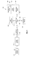
- a typical graphics pipeline provides rendered graphics from a graphics processor 112 over a link 106 to a frame buffer 114 for display via link 107 on a display screen 118.
- the graphics processor 112 may be coupled by a bus 105, such as a Peripheral Component Interconnect (PCI) bus, to a chipset core logic 110.
- the graphics processor 112 may be a multicore processor.
- the core logic 110 is coupled to a main processor or central processing unit (CPU) 100.
- the central processing unit may be one or more processors that handle a variety of processing functions of a computer system, while the graphics processor is dedicated to graphics functions.
- the core logic may also be coupled to removable medium 136, hard drives 134, and main memory 132, which may store a program 139.
- the core logic 110 may be coupled by a link 108 to a keyboard or mouse 120 for control of the display.
- the program 139 may be made up of instructions that are executed by the processor 100 or the processor 112.
- the main memory 132 constitutes one example of a computer readable medium that may store executable instructions in accordance with some embodiments of the present invention.
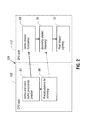
- the central processing unit 100 loads in the control points.
- the control points are the vertices of the polygons that make up the digital image.
- the processor 100 loads in the trimming curves.
- the trimming curves are the curves that can be used to trim patches to create curve shapes.
- An analogy to a patch is a square piece of paper.
- the piece of paper can be folded or crumpled, but it is still always a square piece of paper. Folding or crumpling the square piece of paper does not make it round. Instead, if a circle is cut out of the paper square, the piece of paper can be made round.
- a NURB is a parametric surface in three-dimensional space. Complex surfaces are made up of patches and each patch is a set of points corresponding to a certain pair of parameters u and v, where both u and v are greater than or equal to zero and less that or equal to one.
- a patch in parametric space, a patch is equivalent to the square piece of paper.
- the patches are reshaped, but the patches cannot be made round, any more than you can make the piece of paper round by folding it or crumpling it.
- a patch is made round by trimming.
- a cut is made in parametric space and this cut is called a trimming curve (or a trimming circle if the cut is round or a trimming line if the cut is straight).
- a circular cut generates two surfaces. The first surface is the outside part of the cut (which corresponds to the square piece of paper with a circular hole in it). The second surface is the inside part, which is the disk that is cut out.
- the trimming curves are loaded by the processor 100.
- the pre-calculations for trimming are also done in the processor 100, as indicated in block 66.
- the vertex and index data is calculated on the fly in the processor 100, as indicated at block 64.
- the control points and resulting trimming curves are transferred over the bus 105 to the graphics processor 112 and, particularly, to its vertex shader 68.
- the graphics processor's vertex shader then does the tessellation of the NURBs using the transferred control points.
- the vertex shader in block 68 also transforms the vertices.
- the vertex shader 68 works as follows. The vertex shader does a calculation of a variable, float2 col which is equal to float2 ((float(vertld%g_size))/g_size, (float (vertld/g_size))/g_size). Vertld is the number of the input vertices within the range [0,g_size*g_size]. There are g_size*g_size vertices in total.
- This number of vertices corresponds to the uniform division of [u,v] which is less than or equal to one and greater than or equal to zero in a NURBs parameter space. This step sets up the correspondence between the vertex number and position inside a square.
- the next step is float4 res4 equals EvalSurface (col. x, col. y).
- EvalSurface (col. x, col. y)
- the transformation (u,v) ⁇ (x,y,z) is done by evaluation of a point on a NURB surface.
- the contents of the EvalSurface () function is a well known method of evaluating a point on a surface.
- the rest of the vertex shader passes input parameters to further stages of the graphics pipeline.
- the geometry shader then trims the NURBs using the trimming curves transferred from the central processing unit 100, as also indicated in block 70. To the extent the trimming curves intersect, they are culled along the trim to simplify pieces of the trimming curve obtained by the intersection of two or more trimming segments inside a triangle.
- red (r), green (g), and blue (b) components of the vectors m_trim1 and m_trim2 may contain information about intersections between a trimming curve and adjacent edges to vertices of the processed triangle is determined in the following pseudo code:
- the result of the above code is an output triangle.
- One of the vertices of the output triangle is a vertex of the processed triangle (input [tri_compl]).
- Two other vertices are the points of intersection between the edges of the processed triangles and the trimming curve.
- the processed triangle does not have to be trimmed out as a whole and it does not contain intersection points as processed above. This means that all the vertices are outside the trimmed parts and they just pass through:
- the graphics processor sends these new polygons to the pixel shader 72.
- the pixel shader rasterizes them and renders them to the display 188.
- trimming may be accomplished in a single pass.
- control points of a mesh to be tessellated are transferred to the graphics pipeline, as opposed to transferring an entire set of polygons.
- the geometry shader performs the trimming or tessellated NURB patch, as opposed to using a neutral processing unit.
- graphics processing techniques described herein may be implemented in various hardware architectures. For example, graphics functionality may be integrated within a chipset. Alternatively, a discrete graphics processor may be used. As still another embodiment, the graphics functions may be implemented by a general purpose processor, including a multicore processor.
- references throughout this specification to "one embodiment” or “an embodiment” mean that a particular feature, structure, or characteristic described in connection with the embodiment is included in at least one implementation encompassed within the present invention. Thus, appearances of the phrase “one embodiment” or “in an embodiment” are not necessarily referring to the same embodiment. Furthermore, the particular features, structures, or characteristics may be instituted in other suitable forms other than the particular embodiment illustrated and all such forms may be encompassed within the claims of the present application.
Landscapes
- Physics & Mathematics (AREA)
- General Physics & Mathematics (AREA)
- Engineering & Computer Science (AREA)
- Theoretical Computer Science (AREA)
- Algebra (AREA)
- Mathematical Analysis (AREA)
- Mathematical Optimization (AREA)
- Mathematical Physics (AREA)
- Pure & Applied Mathematics (AREA)
- Computer Graphics (AREA)
- Geometry (AREA)
- Software Systems (AREA)
- Image Generation (AREA)
Abstract
Description
- This relates generally to rendering images in processor-based systems.
- In order to depict complex geometric shapes, those shapes must be represented in mathematical form. In graphics, splines have a parameter value t that varies from zero to one across a surface. The spline may be represented by an equation that weights neighboring points and describes how to combine them to create a curve segment.
- Typically, an entire surface is determined by a combination of splines in three-dimensional space. Thus, a change in one point results in modification of a part of the surface whose size grows proportionally to the degree of the polynomial.
- A B-spline is a curved surface representation. A B-spline provides local control and influence for its various control points. B-splines have the same continuity as natural splines, but they do not interpolate their control points. A control point is a vertex in a polygon that is used to represent shapes of geometric images. The B in B-splines stands for "basis" since the B-splines can be represented as weighted sums of polynomial basis functions.
- A rational B-spline is a ratio of polynomials. A non-uniform rational B-spline or NURB is characterized by the non-uniform location of so-called knots. The knots are the starting values for the spline parameters along a curved segment. By having successive knot values have the same starting value, the curvature of the surface may be affected at that particular point in space.
- If knots are evenly spaced, the surface would be referred to as uniform. Non-uniform in NURB means that the knot positions may not be evenly spaced.
- A trimmed non-uniform rational B-spline or trimmed NURB is arrived at by defining curves on the surface of the NURB and cutting holes in the NURB surface. NURBs allow the representation of high fidelity curved geometries used in games, computer aided design, scientific visualization, and movies.
-
-
Figure 1 is a system depiction for one embodiment; and -
Figure 2 shows the operations on the central processing unit side and graphics processing unit side in the system ofFigure 1 in accordance with one embodiment. - In accordance with some embodiments, trimmed NURBs may be generated by a graphics processor. This avoids the need to send complex graphics information back and forth between the central processing unit and the graphics processor. Such transfers use up available bandwidth and make rendering of complex shapes impractical.
- Referring to
Figure 1 , a typical graphics pipeline provides rendered graphics from agraphics processor 112 over alink 106 to aframe buffer 114 for display vialink 107 on adisplay screen 118. Thegraphics processor 112 may be coupled by abus 105, such as a Peripheral Component Interconnect (PCI) bus, to achipset core logic 110. Thegraphics processor 112 may be a multicore processor. Thecore logic 110 is coupled to a main processor or central processing unit (CPU) 100. The central processing unit may be one or more processors that handle a variety of processing functions of a computer system, while the graphics processor is dedicated to graphics functions. The core logic may also be coupled toremovable medium 136,hard drives 134, andmain memory 132, which may store aprogram 139. Thecore logic 110 may be coupled by alink 108 to a keyboard ormouse 120 for control of the display. Theprogram 139 may be made up of instructions that are executed by theprocessor 100 or theprocessor 112. Thus, themain memory 132 constitutes one example of a computer readable medium that may store executable instructions in accordance with some embodiments of the present invention. - Referring to
Figure 2 , the operations on theCPU 100 andgraphics processor unit 112, via the interveningbus 105, are depicted. Initially, thecentral processing unit 100 loads in the control points. The control points are the vertices of the polygons that make up the digital image. Then, theprocessor 100 loads in the trimming curves. The trimming curves are the curves that can be used to trim patches to create curve shapes. - An analogy to a patch is a square piece of paper. The piece of paper can be folded or crumpled, but it is still always a square piece of paper. Folding or crumpling the square piece of paper does not make it round. Instead, if a circle is cut out of the paper square, the piece of paper can be made round.
- A NURB is a parametric surface in three-dimensional space. Complex surfaces are made up of patches and each patch is a set of points corresponding to a certain pair of parameters u and v, where both u and v are greater than or equal to zero and less that or equal to one.
- So, in parametric space, a patch is equivalent to the square piece of paper. By transferring the parameters u and v into three-dimensional space, the patches are reshaped, but the patches cannot be made round, any more than you can make the piece of paper round by folding it or crumpling it. A patch is made round by trimming.
- A cut is made in parametric space and this cut is called a trimming curve (or a trimming circle if the cut is round or a trimming line if the cut is straight). A circular cut generates two surfaces. The first surface is the outside part of the cut (which corresponds to the square piece of paper with a circular hole in it). The second surface is the inside part, which is the disk that is cut out.
- Thus, the trimming curves are loaded by the
processor 100. The pre-calculations for trimming are also done in theprocessor 100, as indicated inblock 66. In the vertex and index buffer, the vertex and index data is calculated on the fly in theprocessor 100, as indicated atblock 64. The control points and resulting trimming curves are transferred over thebus 105 to thegraphics processor 112 and, particularly, to itsvertex shader 68. - The graphics processor's vertex shader then does the tessellation of the NURBs using the transferred control points. The vertex shader in
block 68 also transforms the vertices. Thevertex shader 68 works as follows. The vertex shader does a calculation of a variable, float2 col which is equal to float2 ((float(vertld%g_size))/g_size, (float (vertld/g_size))/g_size). Vertld is the number of the input vertices within the range [0,g_size*g_size]. There are g_size*g_size vertices in total. This number of vertices (vertld) corresponds to the uniform division of [u,v] which is less than or equal to one and greater than or equal to zero in a NURBs parameter space. This step sets up the correspondence between the vertex number and position inside a square. - The next step is float4 res4 equals EvalSurface (col. x, col. y). For a given position inside the square (col) the transformation (u,v) → (x,y,z) is done by evaluation of a point on a NURB surface. The contents of the EvalSurface () function is a well known method of evaluating a point on a surface. The rest of the vertex shader passes input parameters to further stages of the graphics pipeline.
- The geometry shader, at
block 70, then trims the NURBs using the trimming curves transferred from thecentral processing unit 100, as also indicated inblock 70. To the extent the trimming curves intersect, they are culled along the trim to simplify pieces of the trimming curve obtained by the intersection of two or more trimming segments inside a triangle. - The geometry shader works as follows. First, a vertex normal is computed as follows:
- float3 normal = normalize( cross( edge1, edge2) );
- If the red (r), green (g), and blue (b) components of the vectors m_trim1 and m_trim2 may contain information about intersections between a trimming curve and adjacent edges to vertices of the processed triangle is determined in the following pseudo code:
- if( ( input[0].m_trim1.r ∥ input[0].m_trim1.g ∥ input[0].m_trim1.b ∥
input[0].m_trim2.r ∥ input[0].m_trim2.g ∥ input[0].m_trim2.b ) &&
( input[1].m_trim1.r ∥ input[1].m_trim1.g ∥ input[1].m_trim1.b ∥
input[1].m_trim2.r ∥ input[1].m_trim2.g ∥ input[1].m_trim2.b ) &&
( input[2].m_trim1.r ∥ input[2].m_trim1.g ∥ input[2].m_trim1.b ∥
input[2].m_trim2.r ∥ input[2].m_trim2.g ∥ input[2].m_trim2.b ) ) - Then, all the pairs of vertices are processed to find intersected edges using information about the intersections in the form of the vectors m_trim1 and m_trim2. As a result, an output triangle or quadrangle is produced, depending on how the processed triangle was intersected:
- output.m_posPS = input[tri_compl].m_posPS;
- output.m_posOS = input[tri_compl].m_posOS;
- TriStream.Append( output);
- output.m_posPS = input[tri_compl].m_posPS*coefs[0]+input[nbors[0]].m_posPS*coefs[1];
- output.m_posOS = input[tri_compl].m_posOS*coefs[0]+input[nbors[0]].m_posOS*coefs[1];
- TriStream.Append( output );
- output.m_posPS = input[tri_compl].m_posPS*coefs[2]+input[nbors[1]].m_posPS*coefs[3];
- output.m_posOS = input[tri_compl].m_posOS*coefs[2]+input[nbors[1]].m_osOS*coefs[3];
- TriStream.Append( output );
- The result of the above code is an output triangle. One of the vertices of the output triangle is a vertex of the processed triangle (input [tri_compl]). Two other vertices are the points of intersection between the edges of the processed triangles and the trimming curve. In some cases, the processed triangle does not have to be trimmed out as a whole and it does not contain intersection points as processed above. This means that all the vertices are outside the trimmed parts and they just pass through:
 {
     output.m_posPS = input[0].m_posPS;
     output.m_posOS = input[0].m_posOS;
     TriStream.Append( output);
     output.m_posPS = input[1].m_posPS;
     output.m_posOS = input[1].m_posOS;
     TriStream.Append( output );
     output.m_posPS = input[2].m_posPS;
     output.m_posOS = input[2].m_posOS;
     TriStream.Append( output );
     }
- 1. A method comprising:
- determining trimmed NURBs in a graphics processor (112);
- loading control points from a central processing unit (100) coupled to said graphics processor (112);
- loading trimming curves from said central processing unit (100); and
- trimming the NURB using trimming curves in a geometry shader (70).
- 2. The method of clause 1 including transferring said control points and said trimming curves over a bus (105) to said graphics processor (112).
- 3. The method of clause 1 or clause 2 including using a vertex shader (68) to tessellate a NURB using said control points.
- 4. The method of clause 3 including using said vertex shader (68) to transform vertices.
- 5. The method of clause 4 including sending new polygons to the pixel shader (72) and rasterizing them in the pixel shader (72).
- 6. A graphics processor (112) comprising:
- a geometry shader (70) to trim a NURB patch using a trimming curve; and
- a vertex shader (68) to tessellate the NURB patch using control points.
- 7. The graphics processor (112) of clause 6 to receive said control points from a central processing unit (100).
- 8. The graphics processor (112) of clause 7 to receive said trimming curve from said central processing unit (100).
- 9. The graphics processor (112) of clause 8, said vertex shader (68) to transform vertices.
- 10. The graphics processor (112) of clause 9, said vertex shader (68) to receive polygons and to rasterize them.
- 11. A central processing unit (100) comprising:
- a unit (64) for vertex and index buffer to calculate vertex and index data;
- a device (66) to make pre-calculations for trimming; and
- said processor (100) to transfer control points and a trimming curve to a graphics processor (112) for rendering of a NURB.
- 12. The central processing unit (100) of clause 11 adapted to be coupled to a graphics processor (112) through a chipset core logic (110).
- 13. A system for rendering images, comprising:
- a graphics processor (112) according to any one of clauses 6 to 10; and
- a central processing unit (100) according to any one of clauses 11 to 12;
- wherein the graphics processor (112) and central processing unit (100) are coupleable.
Claims (4)
- A central processing unit (100) comprising:a vertex and index buffer unit (64) to calculate vertex and index data; andcalculation means (66) to perform pre-calculations for trimming; whereinsaid central processing unit (100) is configured to transfer control points and a trimming curve to a graphics processor (112) for rendering a NURB.
- A system for rendering images, comprising:a graphics processor (112) having
a geometry shader (70) to trim a NURB patch using a trimming curve; and
a vertex shader (68) to tessellate the NURB patch using control points;a chipset core logic (110); anda central processing unit (100), coupled to said graphics processor (112) through said chipset core logic (110), said central processing unit (100) having;
a vertex and index buffer unit (64) to calculate vertex and index data; and
calculation means (66) to perform pre-calculations for trimming; whereinsaid central processing unit (100) is arranged to transfer control points and a trimming curve to said graphics processor (112) for rendering the NURB. - The system of claim 2 wherein said vertex shader (68) is adapted to transform vertices.
- The system of claim 3 wherein said vertex shader (68) is adapted to rasterize polygons.
Applications Claiming Priority (2)
| Application Number | Priority Date | Filing Date | Title |
|---|---|---|---|
| US12/286,543 US20100079469A1 (en) | 2008-09-30 | 2008-09-30 | Rendering tremmed nurbs on programmable graphics architectures |
| EP09252305A EP2169615A3 (en) | 2008-09-30 | 2009-09-29 | Rendering trimmed nurbs on programmable graphics architectures |
Related Parent Applications (1)
| Application Number | Title | Priority Date | Filing Date |
|---|---|---|---|
| EP09252305.9 Division | 2009-09-29 |
Publications (2)
| Publication Number | Publication Date |
|---|---|
| EP2568435A2 true EP2568435A2 (en) | 2013-03-13 |
| EP2568435A3 EP2568435A3 (en) | 2013-12-18 |
Family
ID=41343418
Family Applications (2)
| Application Number | Title | Priority Date | Filing Date |
|---|---|---|---|
| EP09252305A Withdrawn EP2169615A3 (en) | 2008-09-30 | 2009-09-29 | Rendering trimmed nurbs on programmable graphics architectures |
| EP12007113.9A Ceased EP2568435A3 (en) | 2008-09-30 | 2009-09-29 | Rendering trimmed NURBs on programmable graphics architectures |
Family Applications Before (1)
| Application Number | Title | Priority Date | Filing Date |
|---|---|---|---|
| EP09252305A Withdrawn EP2169615A3 (en) | 2008-09-30 | 2009-09-29 | Rendering trimmed nurbs on programmable graphics architectures |
Country Status (4)
| Country | Link |
|---|---|
| US (1) | US20100079469A1 (en) |
| EP (2) | EP2169615A3 (en) |
| CN (1) | CN101714248B (en) |
| BR (1) | BRPI0905648A2 (en) |
Families Citing this family (2)
| Publication number | Priority date | Publication date | Assignee | Title |
|---|---|---|---|---|
| ES2363546B2 (en) * | 2011-03-28 | 2012-02-22 | Universidad De Cantabria | "METHOD OF GEOMETRIC DESIGN OF SPACES, BELONGING TO THE FIELD OF ARCHITECTURE AND CIVIL ENGINEERING, BY NURBS SURFACES". |
| US9984496B1 (en) | 2016-08-23 | 2018-05-29 | Bentley Systems, Incorporated | Technique for compact and accurate encoding trim geometry for application in a graphical processing unit |
Family Cites Families (8)
| Publication number | Priority date | Publication date | Assignee | Title |
|---|---|---|---|---|
| US7212205B2 (en) * | 2002-11-12 | 2007-05-01 | Matsushita Electric Industrial Co., Ltd. | Curved surface image processing apparatus and curved surface image processing method |
| US20050275760A1 (en) * | 2004-03-02 | 2005-12-15 | Nvidia Corporation | Modifying a rasterized surface, such as by trimming |
| WO2006034034A2 (en) * | 2004-09-16 | 2006-03-30 | Nvidia Corporation | Load balancing |
| US20070018988A1 (en) * | 2005-07-20 | 2007-01-25 | Michael Guthe | Method and applications for rasterization of non-simple polygons and curved boundary representations |
| CN1928918B (en) * | 2005-10-14 | 2012-10-10 | 威盛电子股份有限公司 | Graphics processing device and method for performing rendering operations in the graphics processing device |
| US7844429B2 (en) * | 2006-07-19 | 2010-11-30 | Align Technology, Inc. | System and method for three-dimensional complete tooth modeling |
| US8643644B2 (en) * | 2008-03-20 | 2014-02-04 | Qualcomm Incorporated | Multi-stage tessellation for graphics rendering |
| CN100573592C (en) * | 2008-03-31 | 2009-12-23 | 北京大学 | A Method for Picking up 3D Geometric Primitives on a Graphics Processor |
-
2008
- 2008-09-30 US US12/286,543 patent/US20100079469A1/en not_active Abandoned
-
2009
- 2009-09-29 EP EP09252305A patent/EP2169615A3/en not_active Withdrawn
- 2009-09-29 EP EP12007113.9A patent/EP2568435A3/en not_active Ceased
- 2009-09-30 BR BRPI0905648-3A patent/BRPI0905648A2/en not_active IP Right Cessation
- 2009-09-30 CN CN200910221456.XA patent/CN101714248B/en not_active Expired - Fee Related
Non-Patent Citations (1)
| Title |
|---|
| None |
Also Published As
| Publication number | Publication date |
|---|---|
| EP2568435A3 (en) | 2013-12-18 |
| BRPI0905648A2 (en) | 2011-03-29 |
| EP2169615A2 (en) | 2010-03-31 |
| EP2169615A3 (en) | 2010-04-28 |
| US20100079469A1 (en) | 2010-04-01 |
| CN101714248A (en) | 2010-05-26 |
| CN101714248B (en) | 2013-04-24 |
Similar Documents
| Publication | Publication Date | Title |
|---|---|---|
| CN104933749B (en) | Clipping of graphics primitives | |
| CN103180882B (en) | Based on the refinement of surface patches in the rendering system of segment | |
| US8289323B2 (en) | Drawing processing apparatus, texture processing apparatus, and tessellation method | |
| JP5224222B2 (en) | A tessellator whose tessellation time increases linearly with the amount of tessellation | |
| JP5721358B2 (en) | Graphics processing system | |
| US20060044312A1 (en) | Rendering outline fonts | |
| CN115147579B (en) | Block rendering mode graphic processing method and system for expanding block boundary | |
| CA2717278A1 (en) | Multi-stage tessellation for graphics rendering | |
| KR20170016301A (en) | Graphics processing | |
| CN101714259B (en) | Graphics processing systems | |
| CN101714258B (en) | Graphics processing systems | |
| KR20160003223A (en) | Tessellation of two-dimensional curves using a graphics pipeline | |
| US10134171B2 (en) | Graphics processing systems | |
| US12293485B2 (en) | Super resolution upscaling | |
| US12493990B2 (en) | Locking mechanism for image classification | |
| KR102853920B1 (en) | Method and apparatus for processing texture | |
| EP2568435A2 (en) | Rendering trimmed NURBs on programmable graphics architectures | |
| Auzinger et al. | Non-Sampled Anti-Aliasing. | |
| US12056823B2 (en) | Segmenting three-dimensional meshes in graphical applications based on detection of elongated shapes | |
| KR102508568B1 (en) | Graphics processing | |
| US9984496B1 (en) | Technique for compact and accurate encoding trim geometry for application in a graphical processing unit | |
| Santina | Resolution independent nurbs curves rendering using programmable graphics pipeline | |
| JPH04137075A (en) | Image reproducer |
Legal Events
| Date | Code | Title | Description |
|---|---|---|---|
| PUAI | Public reference made under article 153(3) epc to a published international application that has entered the european phase |
Free format text: ORIGINAL CODE: 0009012 |
|
| 17P | Request for examination filed |
Effective date: 20121031 |
|
| AC | Divisional application: reference to earlier application |
Ref document number: 2169615 Country of ref document: EP Kind code of ref document: P |
|
| AK | Designated contracting states |
Kind code of ref document: A2 Designated state(s): AT BE BG CH CY CZ DE DK EE ES FI FR GB GR HR HU IE IS IT LI LT LU LV MC MK MT NL NO PL PT RO SE SI SK SM TR |
|
| PUAL | Search report despatched |
Free format text: ORIGINAL CODE: 0009013 |
|
| AK | Designated contracting states |
Kind code of ref document: A3 Designated state(s): AT BE BG CH CY CZ DE DK EE ES FI FR GB GR HR HU IE IS IT LI LT LU LV MC MK MT NL NO PL PT RO SE SI SK SM TR |
|
| RIC1 | Information provided on ipc code assigned before grant |
Ipc: G06T 1/20 20060101AFI20131111BHEP Ipc: G06T 17/30 20060101ALI20131111BHEP |
|
| 17Q | First examination report despatched |
Effective date: 20131202 |
|
| STAA | Information on the status of an ep patent application or granted ep patent |
Free format text: STATUS: THE APPLICATION HAS BEEN REFUSED |
|
| 18R | Application refused |
Effective date: 20180130 |