EP2568393A1 - Electronic calculator - Google Patents
Electronic calculator Download PDFInfo
- Publication number
- EP2568393A1 EP2568393A1 EP10851056A EP10851056A EP2568393A1 EP 2568393 A1 EP2568393 A1 EP 2568393A1 EP 10851056 A EP10851056 A EP 10851056A EP 10851056 A EP10851056 A EP 10851056A EP 2568393 A1 EP2568393 A1 EP 2568393A1
- Authority
- EP
- European Patent Office
- Prior art keywords
- display
- display pattern
- electronic calculator
- digit
- members
- Prior art date
- Legal status (The legal status is an assumption and is not a legal conclusion. Google has not performed a legal analysis and makes no representation as to the accuracy of the status listed.)
- Granted
Links
Images



Classifications
-
- G—PHYSICS
- G06—COMPUTING OR CALCULATING; COUNTING
- G06F—ELECTRIC DIGITAL DATA PROCESSING
- G06F15/00—Digital computers in general; Data processing equipment in general
- G06F15/02—Digital computers in general; Data processing equipment in general manually operated with input through keyboard and computation using a built-in program, e.g. pocket calculators
-
- G—PHYSICS
- G09—EDUCATION; CRYPTOGRAPHY; DISPLAY; ADVERTISING; SEALS
- G09G—ARRANGEMENTS OR CIRCUITS FOR CONTROL OF INDICATING DEVICES USING STATIC MEANS TO PRESENT VARIABLE INFORMATION
- G09G3/00—Control arrangements or circuits, of interest only in connection with visual indicators other than cathode-ray tubes
- G09G3/04—Control arrangements or circuits, of interest only in connection with visual indicators other than cathode-ray tubes for presentation of a single character by selection from a plurality of characters, or by composing the character by combination of individual elements, e.g. segments using a combination of such display devices for composing words, rows or the like, in a frame with fixed character positions
-
- G—PHYSICS
- G09—EDUCATION; CRYPTOGRAPHY; DISPLAY; ADVERTISING; SEALS
- G09G—ARRANGEMENTS OR CIRCUITS FOR CONTROL OF INDICATING DEVICES USING STATIC MEANS TO PRESENT VARIABLE INFORMATION
- G09G2320/00—Control of display operating conditions
- G09G2320/08—Arrangements within a display terminal for setting, manually or automatically, display parameters of the display terminal
-
- G—PHYSICS
- G09—EDUCATION; CRYPTOGRAPHY; DISPLAY; ADVERTISING; SEALS
- G09G—ARRANGEMENTS OR CIRCUITS FOR CONTROL OF INDICATING DEVICES USING STATIC MEANS TO PRESENT VARIABLE INFORMATION
- G09G2340/00—Aspects of display data processing
- G09G2340/14—Solving problems related to the presentation of information to be displayed
Definitions
- This invention relates to an electronic calculator which displays digit grouping.
- digits in a number displayed on a display module are basically arranged in groups of three so as to correspond to 1,000's (thousands), 1,000,000's (millions), 1,000,000,000's (billions), and so on.
- Patent document 1 Jpn. Pat. Appln. KOKAI Publication No. 04-123125
- digit grouping is performed in units of two digits (except for only the last three digits) so as to correspond to 1,000's (Sahastr/Hazaar), 1,00,000's (Lakn), 1,00,00,000's (Crore), 1,00,00,00,000's (Arawb), and so on.
- a decimal point symbol is represented by a period ".”
- a decimal point symbol is represented by a comma "”
- a digit grouping symbol is represented by a period ".”
- an object of the invention to provide an electronic calculator which enables the user to switch a digit grouping symbol placement pattern displayed together with a number on a display module according to a country or a region as needed.
- An electronic calculator comprises a display module in which digit grouping display members and decimal point display members are arranged in the upper part and lower part of a plural-digit number display member.
- the electronic calculator causes display pattern storage means to store a display pattern of digit grouping symbols displayed together with a number on the display module, further causes display pattern selection means to select two types of display patterns according to user operation from the stored digit grouping symbol display patterns, and still further causes selected display pattern storage means to store the selected two types of display patterns. Then, the electronic calculator causes display pattern switching means to switch the stored two types of display patterns according to user operation.
- an electronic calculator which enables the user to switch a digit grouping symbol placement pattern displayed together with a number on a display module according to a country or a region as needed.
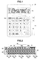
- FIG. 1 is a front view showing an outer configuration of an electronic calculator 10 with a check function according to an embodiment of an electronic calculator of the invention.
- a key input module 11 On the front face of the electronic calculator 10, there are provided a key input module 11 and a segment display module 15.
- the key input module 11 includes a number and operation symbol key group 12 for inputting numbers or instructing to do calculations, a calculation function setting key group 13 for switching symbols or setting a calculation mode using a memory function, a check function key group 14 for reviewing a calculation process using a calculation check function, and a [DISP] key 14d for switching digit grouping display patterns or instructing to set a digit grouping display pattern.
- a [+/-] key, [M+] (memory add) key, [M-] (memory subtract) key, [MRC] (memory clear) key, [MU] (mark up) key, [GT] (grand total) key, and the like are arranged.
- a [GO TO] (calculation step specify) key [AUTO REVIEW] (automatic review) key, [CORRECT] (correct) key, [ ⁇ ] and [ ⁇ ] (calculation step move) keys, and the like are arranged.
- FIG. 2 is a front view showing the configuration of the segment display module 15 of the electronic calculator 10.
- the display module 15 includes 12-digit number display members 16a to 161, period display members 17a to 171 and comma display members 18a to 181 placed at the bottom right of the number display members 16a to 161 respectively, and prime display members 19d to 191 placed at the top right of the number display members 16d to 161 from the fourth to twelfth digits respectively.
- the period display members 17a to 171 are mostly used as decimal points. Any one of the period display members 17a to 171 is displayed according to the number of digits necessary after the decimal point of a displayed number.
- the comma display members 18a to 181 are mostly used for the digit grouping (or a positional representation) of a displayed number. They are displayed at digit positions corresponding to preset six display patterns ( FIGS. 4A to 4F ) to be selected according to a country or a region.
- the prime display members 19d to 191 are mostly used for the digit grouping (or a positional representation) of a number in place of the comma display members 18a to 181.
- the period display members 17a to 171 are sometimes used for the digit grouping (or a positional representation) of a number and the comma display members 18a to 181 are sometimes used as decimal points.
- Each of the operator display members ("%”, “+”, “-” " ⁇ ", “ ⁇ ") 21 is displayed when the corresponding key in the number and operation symbol key group 12 is pressed.
- the step count display member 23 includes, for example, a three-digit number display member. Segments corresponding to the calculation step count of a number displayed by the number display members 16a to 161 are displayed.
- FIG. 3 is a block diagram showing a configuration of the electronic circuitry of the electronic calculator 10.
- the electronic calculator 10 includes a control module (CPU) 31 functioning as a calculator.
- CPU control module
- the control module (CPU) 31 controls the operation of various parts of the circuitry using a RAM 33 as a working memory according to a system program previously stored in a storage device (flash ROM) 32 or an calculator control program externally read in the storage device 32.
- the system program or calculator program previously stored in the storage device 32 is activated in response to a key input signal from the key input module 11 or an inclination detection signal from an inclination detection module 37.
- control module (CPU) 31 Connected to the control module (CPU) 31 are not only the storage device 32, RAM 33, key input module 11, and inclination detection module 37 but also the segment display module 15 via a display control module 15c.
- the inclination detection module 37 includes an acceleration sensor that senses, for example, a unidirectional rotation (inclination).
- the detection module 37 outputs a detection signal when the calculator body is inclined forward in such a manner that the key input module 11 is situated lower than the display module 15 and further outputs a different detection signal when the calculator body is inclined to the opposite side in such a manner that the display module 15 is situated lower than the key input module 11.
- RAM 33 storage areas, including a setting display mode memory 34, a display mode 1 data memory 35a, a display mode 2 data memory 35b, and a calculation history data memory 36, are secured.
- display patterns As display patterns, six types of display patterns (see FIGS. 4A to 4F ) are previously stored according to a decimal point, shapes of symbols used for digit grouping, and the difference between decimal scaling positions displayed on the display module 15.
- the display pattern setting mode is activated by pressing the [DISP] key 14d for an extended time, the user can select arbitrary two from the six types of display patterns.
- pressing the [DISP] key 14d causes the selected two types of display patterns to be switched and the selected one to be set as a display mode.
- calculation history data memory 36 history data items resulting from calculation processes according to user operations on the number and operation symbol key group 12 and calculation function setting key group 13 in the key input module 11 are stored sequentially so as to correspond to the calculation step counts.
- a decimal point is represented by a period and three-digit grouping is used in a "standard specification”
- special digit grouping is used in an "Indian specification”
- a decimal point is represented by a comma and three-digit grouping is used in a "European specification.”
- a pattern that displays grouping separator symbols above a number and a pattern that displays grouping separator symbols below a number are prepared.
- three-digit grouping is performed by prime display members 19d, 19g, 19j so as to correspond to general digit grouping as follows: the 1,000.'s (thousands), 1,000,000.'s (millions), 1,000,000,000.'s (billions), and so on.
- a decimal point is represented by a period display member 17a.
- comma display members 18d, 18g, 18j are used as shown in FIG. 4B .
- a decimal point is represented by a period display member 17a.
- three-digit grouping (positional representation) and subsequent two-digit grouping (positional representation) are performed by prime display members 19d, 19f, 19h, 19j, 191 so as to correspond to digit grouping in India as follows: the 1,000. (Sahastr/Hazaar), 1,00,000.'s (Lakn), 1,00,00,000.'s (Crone), 1,00,00,00,000.'s (Arawb), 1,00,00,00,00,000.'s (Kharawb), and so on.
- a decimal point is represented by a period display member 17a.
- a fourth display pattern Indian specification: down
- three-digit grouping (positional representation) and subsequent two-digit grouping are performed by comma display members 18d, 18f, 18h, 18j, 181 so as to correspond to the digital grouping in India.
- a decimal point is represented by a period display member 17a.
- a fifth display pattern European specification: UP
- three-digit grouping is performed by prime display members 19d, 19g, 19j so as to correspond to digit grouping in the West (non-English-speaking countries or regions) as follows: 1.000's, (thousands), 1.000.000's, (millions), 1.000.000.000's, (billions), and so on.
- a decimal point is represented by a comma display member 18a.
- a sixth display pattern European specification: down
- three-digit grouping is performed by period display members 17d, 17g, 17j so as to correspond to the digit grouping in the West.
- a decimal point is represented by a comma display member 18a.
- any one of the first to sixth display patterns if the decimal place of the decimal point is shifted as a result of calculations, digit grouping separators' positions will be also shifted.
- FIG. 5 is a flowchart to explain entire processing performed by the electronic calculator 10.
- the electronic calculator 10 When a power key (not shown) is pressed, the electronic calculator 10 goes into an operating state and operates according to a key operation on the key input module 11.
- step S1 When pressing of the [DISP] key 14d in the key input module 11 has been detected (Yes in step S1), it is determined whether the [DISP] key 14d has been pressed for an extended time (step S2). If the [DISP] key 14d has been pressed for a specific time or longer (Yes in step S2), the electronic calculator 10 goes into the display pattern setting mode (step S3). In this case, "SET" in the mode display members 22 on the display module 15 is displayed.
- step S4 the first display pattern shown in FIG. 4A is displayed on the display module 15 (step S4).
- the second display pattern shown in FIG. 4B , the third display pattern shown in FIG. 4C , the fourth display pattern shown in FIG. 4D , ... are displayed in that order on the display module 15 each time the [ ⁇ ] key is pressed.
- the sixth display pattern shown in FIG. 4F , the fifth display pattern shown in FIG. 4E , the fourth display pattern shown in FIG. 4D , . . . are displayed in that order on the display module 15 each time the [ ⁇ ] key is pressed (step S5 [Yes] ⁇ S6).
- step S7 After the display pattern has been changed by user operation and a first display pattern the user wants to use has been displayed, when the [DISP] key 14d has been pressed (Yes in step S7), it is determined whether it is a first press of the [DISP] key 14d since the start of the display pattern setting mode (step S8).
- step S8 if it has been determined that it is a first press of the [DISP] key 14d (Yes in step S8), the first display pattern displayed on the display module 15 is stored in the display mode 1 data memory 35a (step S9).
- step S5 [Yes] ⁇ S6
- step S7 it is determined that it is a second press of the [DISP] key 14d (No in step S8).
- step S10 the second display pattern displayed on the display module 15 is stored in the display mode 2 data memory 35b. Thereafter, the display pattern setting mode is deactivated (step S11).
- the third display pattern (Indian specification: UP) shown in FIG. 4C has been set in the display mode 1 data memory 35a and the second display pattern (standard specification: down) shown in FIG. 4B has been set in the display mode 2 data memory 35b according to user operation in the display pattern setting mode.
- step S16 value assignment and a value of the operation result are displayed according to the third display pattern (Indian specification: UP) stored in the display mode 1 data memory 35a set in the setting display mode memory 34.
- step S1 when the user has pressed the [DISP] key 14d as shown in FIG. 6B (step S1 [Yes] ⁇ S2 [No]), the display mode 1 data 35a (third display pattern [Indian specification: UP]) set in the setting display mode memory 34 is switched to to the display mode 2 data 35b (second display pattern [standard specification: down]) (step S12).
- step S14 to S16 Thereafter, in the process of performing value assignment and arithmetic processing according to user operation (steps S14 to S16), each time the [DISP] key 14d is pressed, a display pattern on the display module 15 switches between the third display pattern (Indian specification: UP) set in the display mode 1 data memory 35a and the second display pattern (standard specification: down) set in the display mode 2 data memory 35b (step S1 [Yes] ⁇ S2 [No] ⁇ S12, S13).
- step S1 [Yes] ⁇ S2 [No] ⁇ S12, S13
- the display pattern switching function of the electronic calculator 10 configured as described above, not only the conventional Western three-digit grouping display pattern but also a plurality of types of digit-grouping display patterns differing from country to country or from region to region are included and the user can select/set two from the display patterns according to the user's preference. Since the two types of digit grouping display patterns selected/set by the user are made switchable freely according to the user's preference or a scene where the user uses an electronic calculator, it is possible to prevent digit positions from being read erroneously and improve the visibility of digits (units) and recognition time.
- the electronic calculator 10 explained in the embodiment has not only the display pattern switching function but also the function of switching display patterns according to the inclination of the body explained below.
- FIG. 7 is a flowchart to explain an inclination detection process performed by the electronic calculator 10.
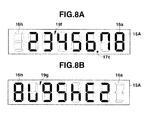
- FIG. 8A shows a concrete example of a number display operation in a body upright state associated with the inclination detection process performed by the electronic calculator 10.
- FIG. 8B shows a concrete example of a number display operation in a body upside-down state associated with the inclination detection process performed by the electronic calculator 10.
- the inclination detection module 37 of the electronic calculator 10 goes into a "no indication detection” state when the body is placed horizontally or inclined in such a manner that the end where the display module lies is located above the rest.
- the inclination detection module 37 goes into an "inclination detection” state when the body where the display module lies is located lower than the rest and outputs the detection signal.
- step S14 For example, suppose the value assignment and arithmetic processing of the electronic calculator 10 (step S14 [Yes] ⁇ S15) shown in FIG. 5 causes the value [23456.78] of the operation result to be displayed as [23'456.78] on the display module 15A as shown in FIG. 8A (step S16) according to the first display pattern (standard specification: UP) set by the user.
- the first display pattern standard specification: UP
- the user inclines the electronic calculator body backward (so as to make the end where the display module is located lie lower than the rest), causing the inclination detection module 37 to output a detection signal of "inclination detection” (step A1 [Yes] ⁇ A2 [Yes]).
- the display mode of the display module 15A is changed to a reversed display mode, with the result that the number [23456.78] displayed until then is changed to a 180-degree reversed state, which is displayed on the display module 15A as shown in FIG. 8B (step A3).
- the prime display member 19g is displayed as a decimal point and the digit grouping (positional representation) according to the first display pattern (standard specification: UP) set by the user is not displayed.
- the inclination detection module 37 outputs a detection signal of "no inclination detection" (step A1 [Yes] ⁇ A4 [Yes]).
- step A5 the display mode of the display module 15A is changed to the preceding display mode, with the result that [23'456.78] is displayed on the display module 15A as shown in FIG. 8A (step A5).
- the user can easily show the contents of the result of calculations done according to user operation to the other party facing the user for confirmation and then easily return the body to the original position to continue the calculations.
- the embodiment has been configured to switch between one display pattern set in the display mode 1 data memory 35a and the other display pattern set in the display mode 2 data memory 35b according to the pressing of the [DISP] key.
- the two display patterns may be switched by the operation of a slide switch or by the movement of the calculator body detected by an acceleration sensor, not by a key operation.
- This invention is not limited to the above embodiments and, in the present or future implementation phase, may be modified variously without departing from the spirit or essential character thereof.
- the embodiments include inventions of different stages and therefore various inventions can be extracted by combining suitably a plurality of structural requirements disclosed in the embodiments. For example, even if some are removed from all of the structural requirements shown in the embodiments or some structure requirements are combined in different modes, the resulting configuration can be extracted as an invention, provided that the object described in OBJECT OF THE INVENTION is accomplished and the advantage described in ADVANTAGE OF THE INVENTION is provided.
Landscapes
- Engineering & Computer Science (AREA)
- Theoretical Computer Science (AREA)
- Physics & Mathematics (AREA)
- Computer Hardware Design (AREA)
- General Physics & Mathematics (AREA)
- Computing Systems (AREA)
- General Engineering & Computer Science (AREA)
- Calculators And Similar Devices (AREA)
- User Interface Of Digital Computer (AREA)
Abstract
Description
- This invention relates to an electronic calculator which displays digit grouping.
- With a conventional electronic calculator, digits in a number displayed on a display module are basically arranged in groups of three so as to correspond to 1,000's (thousands), 1,000,000's (millions), 1,000,000,000's (billions), and so on.
- An electronic calculator that displays a number by grouping the number in units of three digits has been considered (refer to, for example, patent document 1).
- Patent document 1: Jpn. Pat. Appln. KOKAI Publication No.
04-123125 - Although it is common practice in the West to represent a number in units of three digits, digit grouping positions differ from country to country or from region to region.
- For example, in India, digit grouping is performed in units of two digits (except for only the last three digits) so as to correspond to 1,000's (Sahastr/Hazaar), 1,00,000's (Lakn), 1,00,00,000's (Crore), 1,00,00,00,000's (Arawb), and so on.
- Therefore, for example, in India, it is very difficult to use a conventional electronic calculator that displays the number by separating the number in units of three digits.
- Generally, in English-speaking countries, the digit grouping symbol is represented by a comma "," and a decimal point symbol is represented by a period ".". However, in non-English-speaking countries, sometimes a decimal point symbol is represented by a comma "," and a digit grouping symbol is represented by a period ".".
- It is, accordingly, an object of the invention to provide an electronic calculator which enables the user to switch a digit grouping symbol placement pattern displayed together with a number on a display module according to a country or a region as needed.
- An electronic calculator according to
claim 1 comprises a display module in which digit grouping display members and decimal point display members are arranged in the upper part and lower part of a plural-digit number display member. The electronic calculator causes display pattern storage means to store a display pattern of digit grouping symbols displayed together with a number on the display module, further causes display pattern selection means to select two types of display patterns according to user operation from the stored digit grouping symbol display patterns, and still further causes selected display pattern storage means to store the selected two types of display patterns. Then, the electronic calculator causes display pattern switching means to switch the stored two types of display patterns according to user operation. - According to the present invention, there is provided an electronic calculator which enables the user to switch a digit grouping symbol placement pattern displayed together with a number on a display module according to a country or a region as needed.
-
-
FIG. 1 is a front view showing an outer configuration of anelectronic calculator 10 with a check function according to an embodiment of an electronic calculator of the invention; -
FIG. 2 is a front view showing the configuration of asegment display module 15 of theelectronic calculator 10; -
FIG. 3 is a block diagram showing a configuration of the electronic circuitry of theelectronic calculator 10; -
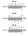
FIG. 4A shows a first display pattern selectable in a display pattern setting mode of theelectronic calculator 10; -
FIG. 4B shows a second display pattern selectable in the display pattern setting mode of theelectronic calculator 10; -
FIG. 4C shows a third display pattern selectable in the display pattern setting mode of theelectronic calculator 10; -
FIG. 4D shows a fourth display pattern selectable in the display pattern setting mode of theelectronic calculator 10; -
FIG. 4E shows a fifth display pattern selectable in the display pattern setting mode of theelectronic calculator 10; -
FIG. 4F shows a sixth display pattern selectable in the display pattern setting mode of theelectronic calculator 10; -
FIG. 5 is a flowchart to explain entire processing performed by theelectronic calculator 10; -
FIG. 6A shows a concrete example of a number display operation in a third display pattern associated with arithmetic processing performed by theelectronic calculator 10; -
FIG. 6B shows a concrete example of a number display operation in a second display pattern associated with arithmetic processing performed by theelectronic calculator 10; -
FIG. 7 is a flowchart to explain an inclination detection process performed by theelectronic calculator 10; -
FIG. 8A shows a concrete example of a number display operation in a body upright state associated with the inclination detection process performed by theelectronic calculator 10; and -
FIG. 8B shows a concrete example of a number display operation in a body upside-down state associated with the inclination detection process performed by theelectronic calculator 10. - Hereinafter, referring to the accompanying drawings, an embodiment of the invention will be explained.
-
FIG. 1 is a front view showing an outer configuration of anelectronic calculator 10 with a check function according to an embodiment of an electronic calculator of the invention. - On the front face of the
electronic calculator 10, there are provided akey input module 11 and asegment display module 15. - The
key input module 11 includes a number and operationsymbol key group 12 for inputting numbers or instructing to do calculations, a calculation function settingkey group 13 for switching symbols or setting a calculation mode using a memory function, a checkfunction key group 14 for reviewing a calculation process using a calculation check function, and a [DISP]key 14d for switching digit grouping display patterns or instructing to set a digit grouping display pattern. - As the number and operation
symbol key group 12, [0] to [9] (number) keys, [+], [-], [×], [÷] and [=] (arithmetic symbol) keys, an [AC] (clear) key, and the like are arranged. - As the calculation function setting
key group 13, a [+/-] key, [M+] (memory add) key, [M-] (memory subtract) key, [MRC] (memory clear) key, [MU] (mark up) key, [GT] (grand total) key, and the like are arranged. - As the check
function key group 14, a [GO TO] (calculation step specify) key, [AUTO REVIEW] (automatic review) key, [CORRECT] (correct) key, [Δ] and [∇] (calculation step move) keys, and the like are arranged. -
FIG. 2 is a front view showing the configuration of thesegment display module 15 of theelectronic calculator 10. - The
display module 15 includes 12-digitnumber display members 16a to 161,period display members 17a to 171 andcomma display members 18a to 181 placed at the bottom right of thenumber display members 16a to 161 respectively, andprime display members 19d to 191 placed at the top right of thenumber display members 16d to 161 from the fourth to twelfth digits respectively. - The period display
members 17a to 171 are mostly used as decimal points. Any one of theperiod display members 17a to 171 is displayed according to the number of digits necessary after the decimal point of a displayed number. - The
comma display members 18a to 181 are mostly used for the digit grouping (or a positional representation) of a displayed number. They are displayed at digit positions corresponding to preset six display patterns (FIGS. 4A to 4F ) to be selected according to a country or a region. - The
prime display members 19d to 191 are mostly used for the digit grouping (or a positional representation) of a number in place of thecomma display members 18a to 181. - In non-English-speaking countries or regions, the
period display members 17a to 171 are sometimes used for the digit grouping (or a positional representation) of a number and thecomma display members 18a to 181 are sometimes used as decimal points. - In addition, the
display module 15 includes prefix display members ("-", "GT", "=") 20 to the left of thenumber display members 16a to 161, operator display members ("%", "+", "-", "×", "÷") 21 at the top right, mode display members ("M", "E", "GOTO", "REV", "CRT", "ANS", "MU", "SET") 22 in the upper part, and a step count display member 23 at the top left. - Of the
prefix display members 20, "-" is displayed when a displayed number is negative, "GT" is displayed when a grand total is displayed according to the pressing of the [GT] (grand total) key, and "-" is displayed when a calculation result is displayed according to the pressing of the [=] (equals) key. - Each of the operator display members ("%", "+", "-" "×", "÷") 21 is displayed when the corresponding key in the number and operation symbol
key group 12 is pressed. - Of the mode display members ("M", "E", "GOTO", "REV", "CRT", "ANS", "MU", "SET") 22, "M" is displayed when a memory mode is on, "E" when an error has occurred, "GOTO" when a calculation step specify mode is activated by the [GO TO] key, "REV" when an automatic review mode is activated by the [AUTO REVIEW] key, "CRT" when a correct mode is activated by the [CORRECT] key, "ANS" when a calculation result display mode is activated by the [=] key, "MU" when a markup mode is activated by the [MU] key, and "SET" when a display pattern setting mode is activated by pressing the [DISP] key 14d for an extended time.
- The step count display member 23 includes, for example, a three-digit number display member. Segments corresponding to the calculation step count of a number displayed by the
number display members 16a to 161 are displayed. -
FIG. 3 is a block diagram showing a configuration of the electronic circuitry of theelectronic calculator 10. - The
electronic calculator 10 includes a control module (CPU) 31 functioning as a calculator. - The control module (CPU) 31 controls the operation of various parts of the circuitry using a
RAM 33 as a working memory according to a system program previously stored in a storage device (flash ROM) 32 or an calculator control program externally read in thestorage device 32. The system program or calculator program previously stored in thestorage device 32 is activated in response to a key input signal from thekey input module 11 or an inclination detection signal from aninclination detection module 37. - Connected to the control module (CPU) 31 are not only the
storage device 32,RAM 33,key input module 11, andinclination detection module 37 but also thesegment display module 15 via adisplay control module 15c. - The
inclination detection module 37 includes an acceleration sensor that senses, for example, a unidirectional rotation (inclination). Thedetection module 37 outputs a detection signal when the calculator body is inclined forward in such a manner that thekey input module 11 is situated lower than thedisplay module 15 and further outputs a different detection signal when the calculator body is inclined to the opposite side in such a manner that thedisplay module 15 is situated lower than thekey input module 11. - In the
RAM 33, storage areas, including a settingdisplay mode memory 34, adisplay mode 1data memory 35a, adisplay mode 2data memory 35b, and a calculationhistory data memory 36, are secured. - In the setting
display mode memory 34, data indicating currently set display patterns is stored. - As display patterns, six types of display patterns (see
FIGS. 4A to 4F ) are previously stored according to a decimal point, shapes of symbols used for digit grouping, and the difference between decimal scaling positions displayed on thedisplay module 15. When the display pattern setting mode is activated by pressing the [DISP] key 14d for an extended time, the user can select arbitrary two from the six types of display patterns. In a normal calculator operating state, pressing the [DISP] key 14d causes the selected two types of display patterns to be switched and the selected one to be set as a display mode. - In the
display mode 1data memory 35a, data indicating one display pattern selected in the display pattern setting mode is stored. - In the
display mode 2data memory 35b, data indicating the other display pattern selected in the display pattern setting mode is stored. - In the calculation
history data memory 36, history data items resulting from calculation processes according to user operations on the number and operation symbolkey group 12 and calculation function settingkey group 13 in thekey input module 11 are stored sequentially so as to correspond to the calculation step counts. - Next, the six types of display patterns will be explained with reference to
FIGS. 4A to 4F . Three types of display patterns are used as follows: a decimal point is represented by a period and three-digit grouping is used in a "standard specification," special digit grouping is used in an "Indian specification," and a decimal point is represented by a comma and three-digit grouping is used in a "European specification." In each type, a pattern that displays grouping separator symbols above a number and a pattern that displays grouping separator symbols below a number are prepared. - As shown in
FIG. 4A , in a first display pattern (standard specification: UP), three-digit grouping (positional representation) is performed byprime display members period display member 17a. - As shown in
FIG. 4B , in a second display pattern (standard specification: down), three-digit grouping (positional representation) is performed bycomma display members period display member 17a. - As shown in
FIG. 4C , in a third display pattern (Indian specification: UP), three-digit grouping (positional representation) and subsequent two-digit grouping (positional representation) are performed byprime display members period display member 17a. - As shown in
FIG. 4D , in a fourth display pattern (Indian specification: down), three-digit grouping (positional representation) and subsequent two-digit grouping (positional representation) are performed bycomma display members period display member 17a. - As shown in
FIG. 4E , in a fifth display pattern (European specification: UP), three-digit grouping (positional representation) is performed byprime display members comma display member 18a. - As shown in
FIG. 4F , in a sixth display pattern (European specification: down), three-digit grouping (positional representation) is performed byperiod display members comma display member 18a. - In any one of the first to sixth display patterns, if the decimal place of the decimal point is shifted as a result of calculations, digit grouping separators' positions will be also shifted.
- Next, the operation of the
electronic calculator 10 with a check function configured as described above will be explained. -
FIG. 5 is a flowchart to explain entire processing performed by theelectronic calculator 10. - When a power key (not shown) is pressed, the
electronic calculator 10 goes into an operating state and operates according to a key operation on thekey input module 11. - When pressing of the [DISP] key 14d in the
key input module 11 has been detected (Yes in step S1), it is determined whether the [DISP] key 14d has been pressed for an extended time (step S2). If the [DISP] key 14d has been pressed for a specific time or longer (Yes in step S2), theelectronic calculator 10 goes into the display pattern setting mode (step S3). In this case, "SET" in themode display members 22 on thedisplay module 15 is displayed. - Then, the first display pattern shown in
FIG. 4A is displayed on the display module 15 (step S4). - Then, when the [∇] key has been pressed, the second display pattern shown in
FIG. 4B , the third display pattern shown inFIG. 4C , the fourth display pattern shown inFIG. 4D , ... are displayed in that order on thedisplay module 15 each time the [∇] key is pressed. In addition, when the [Δ] key has been pressed, the sixth display pattern shown inFIG. 4F , the fifth display pattern shown inFIG. 4E , the fourth display pattern shown inFIG. 4D , . . . are displayed in that order on thedisplay module 15 each time the [Δ] key is pressed (step S5 [Yes] → S6). - After the display pattern has been changed by user operation and a first display pattern the user wants to use has been displayed, when the [DISP] key 14d has been pressed (Yes in step S7), it is determined whether it is a first press of the [DISP] key 14d since the start of the display pattern setting mode (step S8).
- Here, if it has been determined that it is a first press of the [DISP]
key 14d (Yes in step S8), the first display pattern displayed on thedisplay module 15 is stored in thedisplay mode 1data memory 35a (step S9). - Then, after the display pattern has been changed similarly by user operation (step S5 [Yes] → S6) and a second display pattern the user wants to use has been displayed, when the [DISP] key 14d has been pressed (Yes in step S7), it is determined that it is a second press of the [DISP]
key 14d (No in step S8). - Then, the second display pattern displayed on the
display module 15 is stored in thedisplay mode 2data memory 35b (step S10). Thereafter, the display pattern setting mode is deactivated (step S11). - Here, suppose, for example, the third display pattern (Indian specification: UP) shown in
FIG. 4C has been set in thedisplay mode 1data memory 35a and the second display pattern (standard specification: down) shown inFIG. 4B has been set in thedisplay mode 2data memory 35b according to user operation in the display pattern setting mode. - In the setting
display mode memory 34, data indicating the third display pattern (Indian specification: UP) set in thedisplay mode 1data memory 35a is stored as the currently setting display pattern by default. - In this state, when the arithmetic operation [200 × 1350 =] has been performed as shown in
FIG. 6A (Yes in step S14), value assignment and arithmetic processing are performed according to the arithmetic operation (step S15). - In this case, in the
display module 15, value assignment and a value of the operation result are displayed according to the third display pattern (Indian specification: UP) stored in thedisplay mode 1data memory 35a set in the setting display mode memory 34 (step S16). - Specifically, the calculation result of the arithmetic operation [200 × 1350 =] is displayed as [2'70'000.] (2 [Lark] 70 [Sahastr/Hazaar]) as shown in
FIG. 6A . - In this display state, when the user has pressed the [DISP] key 14d as shown in
FIG. 6B (step S1 [Yes] → S2 [No]), thedisplay mode 1data 35a (third display pattern [Indian specification: UP]) set in the settingdisplay mode memory 34 is switched to to thedisplay mode 2data 35b (second display pattern [standard specification: down]) (step S12). - Then, the display of the operation result is switched to [270,000.] (270 [thousand]) as shown in
FIG. 6B (step S13). - Thereafter, in the process of performing value assignment and arithmetic processing according to user operation (steps S14 to S16), each time the [DISP] key 14d is pressed, a display pattern on the
display module 15 switches between the third display pattern (Indian specification: UP) set in thedisplay mode 1data memory 35a and the second display pattern (standard specification: down) set in thedisplay mode 2data memory 35b (step S1 [Yes] → S2 [No] → S12, S13). - Therefore, for example, while a calculation process is being performed according to the Indian specification, a representation in the standard specification can also be checked easily, preventing digit positions from being read erroneously.
- Accordingly, with the display pattern switching function of the
electronic calculator 10 configured as described above, not only the conventional Western three-digit grouping display pattern but also a plurality of types of digit-grouping display patterns differing from country to country or from region to region are included and the user can select/set two from the display patterns according to the user's preference. Since the two types of digit grouping display patterns selected/set by the user are made switchable freely according to the user's preference or a scene where the user uses an electronic calculator, it is possible to prevent digit positions from being read erroneously and improve the visibility of digits (units) and recognition time. - In addition, the
electronic calculator 10 explained in the embodiment has not only the display pattern switching function but also the function of switching display patterns according to the inclination of the body explained below. -
FIG. 7 is a flowchart to explain an inclination detection process performed by theelectronic calculator 10. -
FIG. 8A shows a concrete example of a number display operation in a body upright state associated with the inclination detection process performed by theelectronic calculator 10. -
FIG. 8B shows a concrete example of a number display operation in a body upside-down state associated with the inclination detection process performed by theelectronic calculator 10. - Here, when the
inclination detection module 37 of theelectronic calculator 10 goes into a "no indication detection" state when the body is placed horizontally or inclined in such a manner that the end where the display module lies is located above the rest. In contrast, theinclination detection module 37 goes into an "inclination detection" state when the body where the display module lies is located lower than the rest and outputs the detection signal. - For example, suppose the value assignment and arithmetic processing of the electronic calculator 10 (step S14 [Yes] → S15) shown in
FIG. 5 causes the value [23456.78] of the operation result to be displayed as [23'456.78] on thedisplay module 15A as shown inFIG. 8A (step S16) according to the first display pattern (standard specification: UP) set by the user. - Here, to show the value [23'456.78] displayed on the
display module 15A to the other party facing the user, the user inclines the electronic calculator body backward (so as to make the end where the display module is located lie lower than the rest), causing theinclination detection module 37 to output a detection signal of "inclination detection" (step A1 [Yes] → A2 [Yes]). - Then, the display mode of the
display module 15A is changed to a reversed display mode, with the result that the number [23456.78] displayed until then is changed to a 180-degree reversed state, which is displayed on thedisplay module 15A as shown inFIG. 8B (step A3). - In the reversed display mode, the
prime display member 19g is displayed as a decimal point and the digit grouping (positional representation) according to the first display pattern (standard specification: UP) set by the user is not displayed. - After this, when the user has inclined the calculator body forward to operate the
electronic calculator 10 again, theinclination detection module 37 outputs a detection signal of "no inclination detection" (step A1 [Yes] → A4 [Yes]). - Then, the display mode of the
display module 15A is changed to the preceding display mode, with the result that [23'456.78] is displayed on thedisplay module 15A as shown inFIG. 8A (step A5). - Therefore, with the function of switching display patterns according to the direction of the body of the
electronic calculator 10 configured as described above, when the calculator body is changed from an upright state where the body faces the user to an upside-down state where the body is inclined to the opposite side, a number displayed on thedisplay module 15A is changed to a 180-degree reversed state. When the body is redirected so as to face the user, the number returns to the original representation. - Therefore, the user can easily show the contents of the result of calculations done according to user operation to the other party facing the user for confirmation and then easily return the body to the original position to continue the calculations.
- The embodiment has been configured to switch between one display pattern set in the
display mode 1data memory 35a and the other display pattern set in thedisplay mode 2data memory 35b according to the pressing of the [DISP] key. In contrast, the two display patterns may be switched by the operation of a slide switch or by the movement of the calculator body detected by an acceleration sensor, not by a key operation. - This invention is not limited to the above embodiments and, in the present or future implementation phase, may be modified variously without departing from the spirit or essential character thereof. The embodiments include inventions of different stages and therefore various inventions can be extracted by combining suitably a plurality of structural requirements disclosed in the embodiments. For example, even if some are removed from all of the structural requirements shown in the embodiments or some structure requirements are combined in different modes, the resulting configuration can be extracted as an invention, provided that the object described in OBJECT OF THE INVENTION is accomplished and the advantage described in ADVANTAGE OF THE INVENTION is provided.
-
- 10 ... Electronic calculator with a check function
- 11 ... Key input module
- 12 ... Number and operation symbol key group
- 13 ... Calculation function setting key group
- 14 ... Check function key group
- 14d ... [DISP] key
- 15, 15A ... Segment display module
- 15c ... Display control module
- 16a to 161 ... Number display members
- 17a to 171 ... Period display members
- 18a to 181 ... Comma display members
- 19d to 191 ... Prime display members
- 20 ... Prefix display members
- 21 ... Operator display members
- 22 ... Mode display members
- 23 ... Step count display member
- 31 ... Control module (CPU)
- 32 ... Storage device
- 33 ... RAM
- 34 ... Setting display mode memory
- 35a ...
Display mode 1 data memory - 35b ...
Display mode 2 data memory - 36 ... Calculation history data memory
- 37 ... Inclination detection module
Claims (5)
- An electronic calculator characterized by comprising:a display module in which digit grouping display members and decimal point display members are arranged in the upper part and lower part of a plural-digit number display member;display pattern storage for storing display patterns of digit grouping symbols displayed together with a number on the display module;display pattern selection unit for selecting two types of display patterns according to user operation from the digit grouping symbol display patterns stored in the display pattern storage;selected display pattern storage for storing the two types of display patterns selected by the display pattern selection unit; anddisplay pattern switching unit for switching the two types of display patterns stored by the selected display pattern storage according to user operation.
- The electronic calculator according to claim 1, characterized in that the digit grouping display members in the upper part of the display module are configured to be prime display members and the display members in the lower part are so configured that comma display members and period display members are arranged in parallel.
- The electronic calculator according to claim 2, characterized in that digit grouping symbol display patterns stored in the display pattern storage include a display pattern where digit grouping symbols are arranged in positions corresponding to units of Indian digit grouping.
- The electronic calculator according to claim 3, characterized by comprising
inclination detection unit for detecting an inclination of a calculator body, and
reversed display unit for reversing a number displayed on the display module according to the detection of the inclination of the calculator body by the inclination detection unit. - The electronic calculator according to claim 4, characterized in that a display pattern displayed together with a number on the display module is set in advance as a display pattern with no digit grouping symbol when the number currently displayed on the display module has been reversed by the reversed display unit.
Applications Claiming Priority (1)
| Application Number | Priority Date | Filing Date | Title |
|---|---|---|---|
| PCT/JP2010/057831 WO2011138836A1 (en) | 2010-05-07 | 2010-05-07 | Electronic calculator |
Publications (3)
| Publication Number | Publication Date |
|---|---|
| EP2568393A1 true EP2568393A1 (en) | 2013-03-13 |
| EP2568393A4 EP2568393A4 (en) | 2018-01-10 |
| EP2568393B1 EP2568393B1 (en) | 2021-06-23 |
Family
ID=44903694
Family Applications (1)
| Application Number | Title | Priority Date | Filing Date |
|---|---|---|---|
| EP10851056.1A Active EP2568393B1 (en) | 2010-05-07 | 2010-05-07 | Electronic calculator |
Country Status (3)
| Country | Link |
|---|---|
| EP (1) | EP2568393B1 (en) |
| CN (1) | CN102870102B (en) |
| WO (1) | WO2011138836A1 (en) |
Families Citing this family (4)
| Publication number | Priority date | Publication date | Assignee | Title |
|---|---|---|---|---|
| US20150248874A1 (en) * | 2012-09-28 | 2015-09-03 | Glory Ltd. | Money handling system, money handling apparatus and money handling method |
| JP6331537B2 (en) * | 2014-03-19 | 2018-05-30 | カシオ計算機株式会社 | Variable value display control device, variable value display control method, and program |
| CN105224192A (en) * | 2014-06-19 | 2016-01-06 | 阿里巴巴集团控股有限公司 | A kind of information processing method, device and client |
| CN105893315A (en) * | 2015-12-31 | 2016-08-24 | 乐视移动智能信息技术(北京)有限公司 | Numerical conversion method and device, and mobile phone |
Family Cites Families (10)
| Publication number | Priority date | Publication date | Assignee | Title |
|---|---|---|---|---|
| JPS5451751A (en) * | 1977-09-30 | 1979-04-23 | Canon Inc | Electronic apparatus |
| JPS58190985A (en) * | 1982-04-30 | 1983-11-08 | 日本電気株式会社 | Command receiver with display character inverting function |
| JPH03127948U (en) * | 1990-04-04 | 1991-12-24 | ||
| JPH04123125A (en) | 1990-09-13 | 1992-04-23 | Sharp Corp | Electronic computer |
| CN1036617C (en) * | 1993-12-06 | 1997-12-03 | 互盛股份有限公司 | Terafloating Line Construction |
| JP3264199B2 (en) * | 1997-02-10 | 2002-03-11 | 松下電器産業株式会社 | Operation device for FA equipment |
| JP2000311174A (en) * | 1999-04-28 | 2000-11-07 | Hitachi Ltd | Display device |
| JP2004226634A (en) * | 2003-01-22 | 2004-08-12 | Sharp Corp | Display apparatus |
| CN1253041C (en) * | 2003-08-15 | 2006-04-19 | 英华达(上海)电子有限公司 | Input method switching device and method for mobile phone |
| JP2006003975A (en) * | 2004-06-15 | 2006-01-05 | Tatsuhiro Kimijima | Electronic desk computer |
-
2010
- 2010-05-07 CN CN201080066553.7A patent/CN102870102B/en active Active
- 2010-05-07 WO PCT/JP2010/057831 patent/WO2011138836A1/en not_active Ceased
- 2010-05-07 EP EP10851056.1A patent/EP2568393B1/en active Active
Non-Patent Citations (1)
| Title |
|---|
| See references of WO2011138836A1 * |
Also Published As
| Publication number | Publication date |
|---|---|
| WO2011138836A1 (en) | 2011-11-10 |
| CN102870102B (en) | 2016-01-20 |
| EP2568393B1 (en) | 2021-06-23 |
| EP2568393A4 (en) | 2018-01-10 |
| CN102870102A (en) | 2013-01-09 |
Similar Documents
| Publication | Publication Date | Title |
|---|---|---|
| JP4775332B2 (en) | Image selection apparatus and image selection method | |
| US6919824B2 (en) | Keypad assembly with supplementary buttons and method for operating the same | |
| AU2004220994B2 (en) | Character arrangements, input methods and input device | |
| US11243676B2 (en) | Numerical control system for machine tool | |
| US9720877B2 (en) | Electronic device, method for controlling display of variable, and recording medium recording variable display controlling program | |
| US20100022275A1 (en) | Communication device and input method for same using virtual keyboard | |
| EP2568393B1 (en) | Electronic calculator | |
| JPH06289928A (en) | Programmable controller and method of executing SFC program using the programmable controller | |
| US20020171685A1 (en) | Using icons to represent physical keys in navigation aids | |
| JP2009271771A (en) | Driving operation device | |
| US20140293349A1 (en) | Image display control apparatus, image display control method, and non-transitory storage medium storing instructions executable by image display control apparatus | |
| TWI437554B (en) | Display device,and method for confirming operation of display device | |
| JP5672894B2 (en) | Calculator with printer | |
| JP2009129285A (en) | Display device and display control program | |
| EP2808848B1 (en) | Paper-sheet handling system and paper-sheet handling method | |
| KR100271375B1 (en) | Apparatus for inputting characters with restricted keys, method and telephone terminal using same | |
| EP1059591B1 (en) | Electronic calculation apparatus with currency converting function and storage medium storing currency converting calculation display program | |
| EP1093287A2 (en) | Electronic device having multiple functions | |
| US20060139333A1 (en) | Method for operating an application and mobile terminal used therefor | |
| US20090046066A1 (en) | Operating device for operating a machine tool, a production machine and/or a machine in the form of a robot | |
| JP2000132517A (en) | Electronic equipment with calculation function | |
| JP2007304966A (en) | Mobile terminal device | |
| JP6682040B1 (en) | Programmable display and program | |
| KR20060057374A (en) | Mobile communication terminal equipped with an emoticon input function using a shortcut and its operation method | |
| US20050104905A1 (en) | Character input method and device |
Legal Events
| Date | Code | Title | Description |
|---|---|---|---|
| PUAI | Public reference made under article 153(3) epc to a published international application that has entered the european phase |
Free format text: ORIGINAL CODE: 0009012 |
|
| 17P | Request for examination filed |
Effective date: 20121017 |
|
| AK | Designated contracting states |
Kind code of ref document: A1 Designated state(s): AL AT BE BG CH CY CZ DE DK EE ES FI FR GB GR HR HU IE IS IT LI LT LU LV MC MK MT NL NO PL PT RO SE SI SK SM TR |
|
| DAX | Request for extension of the european patent (deleted) | ||
| RA4 | Supplementary search report drawn up and despatched (corrected) |
Effective date: 20171212 |
|
| RIC1 | Information provided on ipc code assigned before grant |
Ipc: G06F 15/02 20060101AFI20171206BHEP Ipc: G09G 3/04 20060101ALI20171206BHEP |
|
| STAA | Information on the status of an ep patent application or granted ep patent |
Free format text: STATUS: EXAMINATION IS IN PROGRESS |
|
| 17Q | First examination report despatched |
Effective date: 20181119 |
|
| GRAP | Despatch of communication of intention to grant a patent |
Free format text: ORIGINAL CODE: EPIDOSNIGR1 |
|
| STAA | Information on the status of an ep patent application or granted ep patent |
Free format text: STATUS: GRANT OF PATENT IS INTENDED |
|
| INTG | Intention to grant announced |
Effective date: 20210121 |
|
| RIN1 | Information on inventor provided before grant (corrected) |
Inventor name: KIMURA, SATOSHI Inventor name: KOYAMA, HISASHI Inventor name: FURUKAWA, RYOICHI Inventor name: MURAI, YUJI Inventor name: LAU, WANCHUN |
|
| GRAS | Grant fee paid |
Free format text: ORIGINAL CODE: EPIDOSNIGR3 |
|
| GRAA | (expected) grant |
Free format text: ORIGINAL CODE: 0009210 |
|
| STAA | Information on the status of an ep patent application or granted ep patent |
Free format text: STATUS: THE PATENT HAS BEEN GRANTED |
|
| AK | Designated contracting states |
Kind code of ref document: B1 Designated state(s): AL AT BE BG CH CY CZ DE DK EE ES FI FR GB GR HR HU IE IS IT LI LT LU LV MC MK MT NL NO PL PT RO SE SI SK SM TR |
|
| REG | Reference to a national code |
Ref country code: GB Ref legal event code: FG4D |
|
| REG | Reference to a national code |
Ref country code: CH Ref legal event code: EP |
|
| REG | Reference to a national code |
Ref country code: DE Ref legal event code: R096 Ref document number: 602010067172 Country of ref document: DE Ref country code: AT Ref legal event code: REF Ref document number: 1404905 Country of ref document: AT Kind code of ref document: T Effective date: 20210715 |
|
| REG | Reference to a national code |
Ref country code: IE Ref legal event code: FG4D |
|
| REG | Reference to a national code |
Ref country code: LT Ref legal event code: MG9D |
|
| PG25 | Lapsed in a contracting state [announced via postgrant information from national office to epo] |
Ref country code: BG Free format text: LAPSE BECAUSE OF FAILURE TO SUBMIT A TRANSLATION OF THE DESCRIPTION OR TO PAY THE FEE WITHIN THE PRESCRIBED TIME-LIMIT Effective date: 20210923 Ref country code: HR Free format text: LAPSE BECAUSE OF FAILURE TO SUBMIT A TRANSLATION OF THE DESCRIPTION OR TO PAY THE FEE WITHIN THE PRESCRIBED TIME-LIMIT Effective date: 20210623 Ref country code: LT Free format text: LAPSE BECAUSE OF FAILURE TO SUBMIT A TRANSLATION OF THE DESCRIPTION OR TO PAY THE FEE WITHIN THE PRESCRIBED TIME-LIMIT Effective date: 20210623 Ref country code: FI Free format text: LAPSE BECAUSE OF FAILURE TO SUBMIT A TRANSLATION OF THE DESCRIPTION OR TO PAY THE FEE WITHIN THE PRESCRIBED TIME-LIMIT Effective date: 20210623 |
|
| REG | Reference to a national code |
Ref country code: AT Ref legal event code: MK05 Ref document number: 1404905 Country of ref document: AT Kind code of ref document: T Effective date: 20210623 |
|
| PG25 | Lapsed in a contracting state [announced via postgrant information from national office to epo] |
Ref country code: LV Free format text: LAPSE BECAUSE OF FAILURE TO SUBMIT A TRANSLATION OF THE DESCRIPTION OR TO PAY THE FEE WITHIN THE PRESCRIBED TIME-LIMIT Effective date: 20210623 Ref country code: GR Free format text: LAPSE BECAUSE OF FAILURE TO SUBMIT A TRANSLATION OF THE DESCRIPTION OR TO PAY THE FEE WITHIN THE PRESCRIBED TIME-LIMIT Effective date: 20210924 Ref country code: SE Free format text: LAPSE BECAUSE OF FAILURE TO SUBMIT A TRANSLATION OF THE DESCRIPTION OR TO PAY THE FEE WITHIN THE PRESCRIBED TIME-LIMIT Effective date: 20210623 Ref country code: NO Free format text: LAPSE BECAUSE OF FAILURE TO SUBMIT A TRANSLATION OF THE DESCRIPTION OR TO PAY THE FEE WITHIN THE PRESCRIBED TIME-LIMIT Effective date: 20210923 |
|
| REG | Reference to a national code |
Ref country code: NL Ref legal event code: MP Effective date: 20210623 |
|
| PG25 | Lapsed in a contracting state [announced via postgrant information from national office to epo] |
Ref country code: CZ Free format text: LAPSE BECAUSE OF FAILURE TO SUBMIT A TRANSLATION OF THE DESCRIPTION OR TO PAY THE FEE WITHIN THE PRESCRIBED TIME-LIMIT Effective date: 20210623 Ref country code: EE Free format text: LAPSE BECAUSE OF FAILURE TO SUBMIT A TRANSLATION OF THE DESCRIPTION OR TO PAY THE FEE WITHIN THE PRESCRIBED TIME-LIMIT Effective date: 20210623 Ref country code: SK Free format text: LAPSE BECAUSE OF FAILURE TO SUBMIT A TRANSLATION OF THE DESCRIPTION OR TO PAY THE FEE WITHIN THE PRESCRIBED TIME-LIMIT Effective date: 20210623 Ref country code: SM Free format text: LAPSE BECAUSE OF FAILURE TO SUBMIT A TRANSLATION OF THE DESCRIPTION OR TO PAY THE FEE WITHIN THE PRESCRIBED TIME-LIMIT Effective date: 20210623 Ref country code: PT Free format text: LAPSE BECAUSE OF FAILURE TO SUBMIT A TRANSLATION OF THE DESCRIPTION OR TO PAY THE FEE WITHIN THE PRESCRIBED TIME-LIMIT Effective date: 20211025 Ref country code: NL Free format text: LAPSE BECAUSE OF FAILURE TO SUBMIT A TRANSLATION OF THE DESCRIPTION OR TO PAY THE FEE WITHIN THE PRESCRIBED TIME-LIMIT Effective date: 20210623 Ref country code: RO Free format text: LAPSE BECAUSE OF FAILURE TO SUBMIT A TRANSLATION OF THE DESCRIPTION OR TO PAY THE FEE WITHIN THE PRESCRIBED TIME-LIMIT Effective date: 20210623 Ref country code: ES Free format text: LAPSE BECAUSE OF FAILURE TO SUBMIT A TRANSLATION OF THE DESCRIPTION OR TO PAY THE FEE WITHIN THE PRESCRIBED TIME-LIMIT Effective date: 20210623 Ref country code: AT Free format text: LAPSE BECAUSE OF FAILURE TO SUBMIT A TRANSLATION OF THE DESCRIPTION OR TO PAY THE FEE WITHIN THE PRESCRIBED TIME-LIMIT Effective date: 20210623 |
|
| PG25 | Lapsed in a contracting state [announced via postgrant information from national office to epo] |
Ref country code: PL Free format text: LAPSE BECAUSE OF FAILURE TO SUBMIT A TRANSLATION OF THE DESCRIPTION OR TO PAY THE FEE WITHIN THE PRESCRIBED TIME-LIMIT Effective date: 20210623 |
|
| REG | Reference to a national code |
Ref country code: DE Ref legal event code: R097 Ref document number: 602010067172 Country of ref document: DE |
|
| PG25 | Lapsed in a contracting state [announced via postgrant information from national office to epo] |
Ref country code: DK Free format text: LAPSE BECAUSE OF FAILURE TO SUBMIT A TRANSLATION OF THE DESCRIPTION OR TO PAY THE FEE WITHIN THE PRESCRIBED TIME-LIMIT Effective date: 20210623 |
|
| PLBE | No opposition filed within time limit |
Free format text: ORIGINAL CODE: 0009261 |
|
| STAA | Information on the status of an ep patent application or granted ep patent |
Free format text: STATUS: NO OPPOSITION FILED WITHIN TIME LIMIT |
|
| 26N | No opposition filed |
Effective date: 20220324 |
|
| PG25 | Lapsed in a contracting state [announced via postgrant information from national office to epo] |
Ref country code: AL Free format text: LAPSE BECAUSE OF FAILURE TO SUBMIT A TRANSLATION OF THE DESCRIPTION OR TO PAY THE FEE WITHIN THE PRESCRIBED TIME-LIMIT Effective date: 20210623 |
|
| PG25 | Lapsed in a contracting state [announced via postgrant information from national office to epo] |
Ref country code: IT Free format text: LAPSE BECAUSE OF FAILURE TO SUBMIT A TRANSLATION OF THE DESCRIPTION OR TO PAY THE FEE WITHIN THE PRESCRIBED TIME-LIMIT Effective date: 20210623 |
|
| REG | Reference to a national code |
Ref country code: CH Ref legal event code: PL |
|
| REG | Reference to a national code |
Ref country code: BE Ref legal event code: MM Effective date: 20220531 |
|
| GBPC | Gb: european patent ceased through non-payment of renewal fee |
Effective date: 20220507 |
|
| PG25 | Lapsed in a contracting state [announced via postgrant information from national office to epo] |
Ref country code: MC Free format text: LAPSE BECAUSE OF FAILURE TO SUBMIT A TRANSLATION OF THE DESCRIPTION OR TO PAY THE FEE WITHIN THE PRESCRIBED TIME-LIMIT Effective date: 20210623 Ref country code: LU Free format text: LAPSE BECAUSE OF NON-PAYMENT OF DUE FEES Effective date: 20220507 Ref country code: LI Free format text: LAPSE BECAUSE OF NON-PAYMENT OF DUE FEES Effective date: 20220531 Ref country code: CH Free format text: LAPSE BECAUSE OF NON-PAYMENT OF DUE FEES Effective date: 20220531 |
|
| PG25 | Lapsed in a contracting state [announced via postgrant information from national office to epo] |
Ref country code: IE Free format text: LAPSE BECAUSE OF NON-PAYMENT OF DUE FEES Effective date: 20220507 Ref country code: FR Free format text: LAPSE BECAUSE OF NON-PAYMENT OF DUE FEES Effective date: 20220531 |
|
| PG25 | Lapsed in a contracting state [announced via postgrant information from national office to epo] |
Ref country code: GB Free format text: LAPSE BECAUSE OF NON-PAYMENT OF DUE FEES Effective date: 20220507 Ref country code: BE Free format text: LAPSE BECAUSE OF NON-PAYMENT OF DUE FEES Effective date: 20220531 |
|
| PG25 | Lapsed in a contracting state [announced via postgrant information from national office to epo] |
Ref country code: HU Free format text: LAPSE BECAUSE OF FAILURE TO SUBMIT A TRANSLATION OF THE DESCRIPTION OR TO PAY THE FEE WITHIN THE PRESCRIBED TIME-LIMIT; INVALID AB INITIO Effective date: 20100507 |
|
| PG25 | Lapsed in a contracting state [announced via postgrant information from national office to epo] |
Ref country code: MK Free format text: LAPSE BECAUSE OF FAILURE TO SUBMIT A TRANSLATION OF THE DESCRIPTION OR TO PAY THE FEE WITHIN THE PRESCRIBED TIME-LIMIT Effective date: 20210623 Ref country code: CY Free format text: LAPSE BECAUSE OF FAILURE TO SUBMIT A TRANSLATION OF THE DESCRIPTION OR TO PAY THE FEE WITHIN THE PRESCRIBED TIME-LIMIT Effective date: 20210623 |
|
| PG25 | Lapsed in a contracting state [announced via postgrant information from national office to epo] |
Ref country code: TR Free format text: LAPSE BECAUSE OF FAILURE TO SUBMIT A TRANSLATION OF THE DESCRIPTION OR TO PAY THE FEE WITHIN THE PRESCRIBED TIME-LIMIT Effective date: 20210623 |
|
| PG25 | Lapsed in a contracting state [announced via postgrant information from national office to epo] |
Ref country code: MT Free format text: LAPSE BECAUSE OF FAILURE TO SUBMIT A TRANSLATION OF THE DESCRIPTION OR TO PAY THE FEE WITHIN THE PRESCRIBED TIME-LIMIT Effective date: 20210623 |
|
| PGFP | Annual fee paid to national office [announced via postgrant information from national office to epo] |
Ref country code: DE Payment date: 20250402 Year of fee payment: 16 |