EP2568357A2 - Computer mouse - Google Patents
Computer mouse Download PDFInfo
- Publication number
- EP2568357A2 EP2568357A2 EP11777557A EP11777557A EP2568357A2 EP 2568357 A2 EP2568357 A2 EP 2568357A2 EP 11777557 A EP11777557 A EP 11777557A EP 11777557 A EP11777557 A EP 11777557A EP 2568357 A2 EP2568357 A2 EP 2568357A2
- Authority
- EP
- European Patent Office
- Prior art keywords
- sliding rod
- computer mouse
- receiving pipe
- mouse
- receiving
- Prior art date
- Legal status (The legal status is an assumption and is not a legal conclusion. Google has not performed a legal analysis and makes no representation as to the accuracy of the status listed.)
- Withdrawn
Links
Images


Classifications
-
- G—PHYSICS
- G06—COMPUTING; CALCULATING OR COUNTING
- G06F—ELECTRIC DIGITAL DATA PROCESSING
- G06F3/00—Input arrangements for transferring data to be processed into a form capable of being handled by the computer; Output arrangements for transferring data from processing unit to output unit, e.g. interface arrangements
- G06F3/01—Input arrangements or combined input and output arrangements for interaction between user and computer
- G06F3/03—Arrangements for converting the position or the displacement of a member into a coded form
- G06F3/033—Pointing devices displaced or positioned by the user, e.g. mice, trackballs, pens or joysticks; Accessories therefor
- G06F3/0354—Pointing devices displaced or positioned by the user, e.g. mice, trackballs, pens or joysticks; Accessories therefor with detection of 2D relative movements between the device, or an operating part thereof, and a plane or surface, e.g. 2D mice, trackballs, pens or pucks
- G06F3/03543—Mice or pucks
Definitions
- the present invention relates to a computer mouse including a sliding member.
- a sliding member included in a computer mouse is used to reduce friction between a bottom surface of a mouse body and a mouse pad, as disclosed in Japanese Utility Model Registration No. 03143935 (August 7, 2008 ) shown in FIG. 1 .
- a sliding member is a thin plate 3 is adhesively inserted by using an adhesive into a shallow groove 2 formed in a bottom surface 1 of a mouse body 4. The sliding member may be easily worn out.
- the present invention provides a computer mouse including a sliding member to be used for a long period time.
- a computer mouse including a sliding member having a shape of a sliding rod, in which the sliding rod is accommodated in a mouse body, and the lower end thereof protrudes from the bottom surface of the mouse body.
- a computer mouse including a sliding rod that is accommodated in a mouse body by being screwed,
- a screwdriver which is used to protrude the lower end portion of the sliding rod from a bottom surface of the mouse body, can be stored in the computer mouse.
- a computer mouse according to an embodiment of the present invention includes a sliding member having a shape of a sliding rod to be used for a long period time.
- the sliding rod can be replaced with a new one.
- no new computer mouse needs to be bought.
- a computer mouse since a computer mouse according to another embodiment of the present invention allows a screwdriver used to protrude a sliding rod from a bottom surface of a mouse body to be stored therein, the screwdriver may be conveniently used any time.
- FIGS. 2 through 4 illustrate a computer mouse 30, according to an embodiment of the present invention.
- the computer mouse 30 includes a sliding member 20.
- a receiving pipe 11 is formed upward from the mouse body 10 of the computer mouse 30.
- the sliding member 20 having a shape of a sliding rod 21 and received in the receiving pipe 11, wherein a lower end of the sliding rod 21 protrudes from the bottom surface 10a of the mouse body 10.
- the receiving pipe 11 has a first screw thread 11 a on an inner circumferential surface thereof, a screwdriver groove 21 a is cut into a top surface of the sliding rod 21, and a second screw thread 21 b is formed on an outer circumferential surface of the sliding rod 21 and is coupled with the first screw thread 11 a formed on the inner circumferential surface of the receiving pipe 11
- An anti-separation set screw 22 for preventing separation of the sliding rod 21 from the receiving pipe 11 is coupled to the first screw thread 11 a formed on the inner circumferential surface of the receiving pipe 11 over the sliding rod 21.
- Notches 21 d may be formed in a longitudinal direction in an outer surface of the sliding rod 21.
- the first screw thread 11 a is formed on the inner circumferential surface of the receiving pipe 11, an edge portion 11b is formed on a lower portion of the first screw thread 11 a, a protruding portion 21 c protrudes upward from the sliding rod 21, a spring 23 is inserted between the protruding portion 21 c and the edge portion 11 b, the anti-separation set screw 22 for preventing separation of the sliding rod 21 is coupled to the first screw thread 11a formed on the inner circumferential surface of the receiving pipe 11 over the sliding rod 21, and a cross-sectional surface of the sliding rod 21 and a hole 11 c of the receiving pipe 11 formed in the bottom surface 10a may have oval shapes.
- the cross-sectional surface of the sliding rod 21 may have an oval shape and the notches 21 d may be formed in the longitudinal direction in the outer surface of the sliding rod 21.
- FIGS. 5 and 6 illustrate the mouse 30 according to another embodiment of the present invention.
- a receiving hole 12 for receiving a screwdriver 24 is formed in the mouse body 10, and the screwdriver 24 is received in the receiving hole 12.
- a receiving case 14 for receiving the screwdriver 24 is coupled to a cable 13 connected to the mouse body 10, and the screwdriver 24 may be received in the receiving case 14.
- reference numeral 10b denotes a cover and 15 denotes a universal serial bus (USB) connector.
- USB universal serial bus
- the present invention may be applied to a computer mouse including a sliding member.
Abstract
A computer mouse includes a sliding member having a shape of a sliding rod to be used for a long period of time. The sliding rod is accommodated in a mouse body, and the lower end of sliding rod protrudes from the bottom of the mouse body. In addition, a screwdriver, which is used for enabling the sliding rod to protrude from the bottom of the mouse body, can be stored together with the computer mouse
Description
- The present invention relates to a computer mouse including a sliding member.
- A sliding member included in a computer mouse is used to reduce friction between a bottom surface of a mouse body and a mouse pad, as disclosed in Japanese Utility Model Registration No.
03143935 (August 7, 2008 FIG. 1 . Referring toFIG. 1 , a sliding member is a thin plate 3 is adhesively inserted by using an adhesive into ashallow groove 2 formed in abottom surface 1 of amouse body 4. The sliding member may be easily worn out. - The present invention provides a computer mouse including a sliding member to be used for a long period time.
- According to an aspect of the present invention, there is provided a computer mouse including a sliding member having a shape of a sliding rod, in which the sliding rod is accommodated in a mouse body, and the lower end thereof protrudes from the bottom surface of the mouse body.
- According to another aspect of the present invention, there is provided a computer mouse including a sliding rod that is accommodated in a mouse body by being screwed, In addition, a screwdriver, which is used to protrude the lower end portion of the sliding rod from a bottom surface of the mouse body, can be stored in the computer mouse.
- Since a computer mouse according to an embodiment of the present invention includes a sliding member having a shape of a sliding rod to be used for a long period time. When the sliding rod is worn out, the sliding rod can be replaced with a new one. Thus, no new computer mouse needs to be bought.
- Also, since a computer mouse according to another embodiment of the present invention allows a screwdriver used to protrude a sliding rod from a bottom surface of a mouse body to be stored therein, the screwdriver may be conveniently used any time.
-
-
FIG. 1 is an enlarged, partial cross-sectional view illustrating a conventional computer mouse. -
FIG. 2 is an enlarged, partial cross-sectional view illustrating a computer mouse in which a sliding member is received, according to an embodiment of the present invention. -
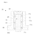
FIG. 3 is an enlarged, partial cross-sectional view illustrating a modified example of the computer mouse ofFIG. 2 . -
FIG. 4 is an enlarged, partial cross-sectional view illustrating a bottom surface of the computer mouse ofFIG. 3 . -
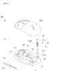
FIG. 5 is an exploded perspective view illustrating a computer mouse in which a screwdriver is received, according to another embodiment of the present invention. -
FIG. 6 is a perspective view illustrating a modified example of the computer mouse ofFIG. 5 . - The present invention will now be described more fully with reference to the accompanying drawings, in which exemplary embodiments of the invention are shown. It will be understood by one of ordinary skill in the art that the embodiments should be considered in a descriptive sense only and not for purposes of limitation, and the spirit and scope of the one or more embodiments of the present invention is defined by the following claims.
-
FIGS. 2 through 4 illustrate acomputer mouse 30, according to an embodiment of the present invention. Referring toFIGS. 2 through 4 , thecomputer mouse 30 includes a slidingmember 20. A receivingpipe 11 is formed upward from themouse body 10 of thecomputer mouse 30. The slidingmember 20 having a shape of asliding rod 21 and received in the receivingpipe 11, wherein a lower end of the slidingrod 21 protrudes from thebottom surface 10a of themouse body 10. - The
receiving pipe 11 has afirst screw thread 11 a on an inner circumferential surface thereof, ascrewdriver groove 21 a is cut into a top surface of thesliding rod 21, and asecond screw thread 21 b is formed on an outer circumferential surface of thesliding rod 21 and is coupled with thefirst screw thread 11 a formed on the inner circumferential surface of thereceiving pipe 11 - An anti-separation set
screw 22 for preventing separation of the slidingrod 21 from thereceiving pipe 11 is coupled to thefirst screw thread 11 a formed on the inner circumferential surface of the receivingpipe 11 over thesliding rod 21. -
Notches 21 d may be formed in a longitudinal direction in an outer surface of thesliding rod 21. - The
first screw thread 11 a is formed on the inner circumferential surface of thereceiving pipe 11, anedge portion 11b is formed on a lower portion of thefirst screw thread 11 a, a protrudingportion 21 c protrudes upward from thesliding rod 21, aspring 23 is inserted between the protrudingportion 21 c and theedge portion 11 b, the anti-separation setscrew 22 for preventing separation of the slidingrod 21 is coupled to thefirst screw thread 11a formed on the inner circumferential surface of the receivingpipe 11 over thesliding rod 21, and a cross-sectional surface of thesliding rod 21 and ahole 11 c of thereceiving pipe 11 formed in thebottom surface 10a may have oval shapes. - The cross-sectional surface of the
sliding rod 21 may have an oval shape and thenotches 21 d may be formed in the longitudinal direction in the outer surface of thesliding rod 21. -
FIGS. 5 and6 illustrate themouse 30 according to another embodiment of the present invention. Referring toFIGS. 5 and6 , a receivinghole 12 for receiving ascrewdriver 24 is formed in themouse body 10, and thescrewdriver 24 is received in thereceiving hole 12. Alternatively, a receivingcase 14 for receiving thescrewdriver 24 is coupled to acable 13 connected to themouse body 10, and thescrewdriver 24 may be received in the receivingcase 14. - In
FIGS. 5 and6 ,reference numeral 10b denotes a cover and 15 denotes a universal serial bus (USB) connector. - The present invention may be applied to a computer mouse including a sliding member.
Claims (7)
- A computer mouse, the computer mouse comprising:a mouse body;a receiving pipe formed upward from a bottom surface of the mouse body; anda sliding member having a shape of a sliding rod and received in the receiving pipe, wherein a lower end of the sliding rod protrudes from the bottom surface of the mouse body.
- The computer mouse of claim 1, wherein the receiving pipe has a first screw thread on an inner circumferential surface thereof, a screwdriver groove is cut into a top surface of the sliding rod, and a second screw thread is formed on an outer circumferential surface of the sliding rod and is coupled with the first screw thread formed on the inner circumferential surface of the receiving pipe.
- The computer mouse of claim 2, further comprising an anti-separation set screw for preventing separation of the sliding rod from the receiving pipe is coupled to the first screw thread formed on the inner circumferential surface of the receiving pipe over the sliding rod.
- The computer mouse of claim 1, wherein the receiving pipe has a first screw thread on an inner circumferential surface of the receiving pipe, an edge portion is formed on a lower portion of the first screw thread, a protruding portion protrudes upward and outward from the sliding rod, a spring is inserted between the protruding portion and the edge portion, an anti-separation set screw for preventing separation of the sliding rod is coupled to the first screw thread formed on the inner circumferential surface of the receiving pipe over the sliding rod, and a hole of the receiving pipe, which is formed in the bottom surface of the mouse body, and a cross-sectional surface of the sliding rod have oval shapes.
- The computer mouse of claim 1, wherein the sliding rod has notches formed in a longitudinal direction in an outer surface of the sliding rod, and a cross-sectional surface of the sliding rod has an oval shape.
- The computer mouse of claim 1, wherein the mouse body has a receiving hole for receiving a screwdriver, and the screwdriver is received in the receiving hole.
- The computer mouse of claim 1, wherein the mouse body is connected to a cable and a receiving case for receiving a screwdriver is connected to the cable.
Applications Claiming Priority (4)
| Application Number | Priority Date | Filing Date | Title |
|---|---|---|---|
| KR2020100004661U KR200451213Y1 (en) | 2010-05-03 | 2010-05-03 | Computer mouse |
| KR20100012415 | 2010-11-30 | ||
| KR2020110001498U KR200458438Y1 (en) | 2010-11-30 | 2011-02-21 | a computer mouse |
| PCT/KR2011/003314 WO2011139076A2 (en) | 2010-05-03 | 2011-05-03 | Computer mouse |
Publications (1)
| Publication Number | Publication Date |
|---|---|
| EP2568357A2 true EP2568357A2 (en) | 2013-03-13 |
Family
ID=44904215
Family Applications (1)
| Application Number | Title | Priority Date | Filing Date |
|---|---|---|---|
| EP11777557A Withdrawn EP2568357A2 (en) | 2010-05-03 | 2011-05-03 | Computer mouse |
Country Status (8)
| Country | Link |
|---|---|
| US (1) | US20120319955A1 (en) |
| EP (1) | EP2568357A2 (en) |
| JP (1) | JP2013528862A (en) |
| CN (1) | CN102893240A (en) |
| AU (1) | AU2011249220A1 (en) |
| BR (1) | BR112012028168A2 (en) |
| SG (1) | SG186141A1 (en) |
| WO (1) | WO2011139076A2 (en) |
Families Citing this family (2)
| Publication number | Priority date | Publication date | Assignee | Title |
|---|---|---|---|---|
| CN103365435B (en) * | 2012-03-26 | 2017-07-21 | 富泰华工业(深圳)有限公司 | Mouse |
| US10386939B2 (en) * | 2017-09-07 | 2019-08-20 | Dexin Electronic Ltd. | Mouse |
Family Cites Families (9)
| Publication number | Priority date | Publication date | Assignee | Title |
|---|---|---|---|---|
| US4744955A (en) * | 1986-08-08 | 1988-05-17 | Shapiro Justin J | Adjustable volume pipette sampler |
| US6749590B2 (en) * | 2000-12-04 | 2004-06-15 | Bracco Diagnostics, Inc. | Syringe barrel and plunger assembly having ellipsoidal configurations |
| US6724366B2 (en) * | 2001-04-03 | 2004-04-20 | Peter James Crawford | Thumb actuated x-y input device |
| KR20020080929A (en) * | 2001-04-18 | 2002-10-26 | 박신성 | Mouse for computer |
| KR200285024Y1 (en) * | 2002-04-30 | 2002-08-13 | 김상훈 | Advanced Mouse Equipped with Roller |
| US20040080494A1 (en) * | 2002-10-29 | 2004-04-29 | International Business Machines Corporation | Force-sensing mouse pointing device for computer input |
| US7748939B2 (en) * | 2007-05-11 | 2010-07-06 | Lockheed Martin Corporation | Captive fastener with unique engaging and locking mechanism |
| JP3143935U (en) * | 2008-05-30 | 2008-08-07 | 忠献 林 | Mouse bottom pad |
| KR200449079Y1 (en) * | 2008-08-27 | 2010-06-10 | 이장일 | Linear motion mouse |
-
2011
- 2011-05-03 WO PCT/KR2011/003314 patent/WO2011139076A2/en active Application Filing
- 2011-05-03 JP JP2013508991A patent/JP2013528862A/en not_active Withdrawn
- 2011-05-03 BR BR112012028168A patent/BR112012028168A2/en not_active IP Right Cessation
- 2011-05-03 SG SG2012088779A patent/SG186141A1/en unknown
- 2011-05-03 CN CN201180022564.XA patent/CN102893240A/en active Pending
- 2011-05-03 US US13/581,755 patent/US20120319955A1/en not_active Abandoned
- 2011-05-03 EP EP11777557A patent/EP2568357A2/en not_active Withdrawn
- 2011-05-03 AU AU2011249220A patent/AU2011249220A1/en not_active Abandoned
Non-Patent Citations (1)
| Title |
|---|
| See references of WO2011139076A3 * |
Also Published As
| Publication number | Publication date |
|---|---|
| US20120319955A1 (en) | 2012-12-20 |
| SG186141A1 (en) | 2013-01-30 |
| AU2011249220A1 (en) | 2013-01-10 |
| BR112012028168A2 (en) | 2018-05-15 |
| JP2013528862A (en) | 2013-07-11 |
| WO2011139076A2 (en) | 2011-11-10 |
| WO2011139076A3 (en) | 2012-01-26 |
| CN102893240A (en) | 2013-01-23 |
Similar Documents
| Publication | Publication Date | Title |
|---|---|---|
| EP1564847A1 (en) | Connector cover for portable terminal | |
| AU2018101268A4 (en) | A case for a tablet shaped device | |
| NZ603299A (en) | Tangless helical coil insert inserting tool | |
| US8956236B2 (en) | Universal joint structure for a tool | |
| EP2985120A3 (en) | Tool pen with detachable function | |
| EP2568357A2 (en) | Computer mouse | |
| US9187305B1 (en) | Screw cap removal tool | |
| JP6240033B2 (en) | Retaining connector | |
| US20140220828A1 (en) | Signal connector module | |
| US20120126556A1 (en) | Tweezers | |
| US8986035B2 (en) | Securing member for a connector | |
| EP2919566B1 (en) | Usb data card | |
| US20140290316A1 (en) | Anti-theft display hanger for a socket | |
| CN206212469U (en) | A kind of driving power supply shell | |
| CN204367709U (en) | A kind of multi-functional triangular ruler | |
| WO2015052589A2 (en) | Connector | |
| US10085356B2 (en) | Electronic device with locking assembly | |
| CN204363636U (en) | Be convenient to the spoon that thumb disabled person uses | |
| JP3122512U (en) | screwdriver | |
| JP3205339U (en) | Outlet connection structure | |
| JP3193983U (en) | Conversion adapter | |
| KR101009377B1 (en) | A diary binder | |
| WO2010013988A3 (en) | Computer mouse | |
| CN201821594U (en) | USB (universal serial bus) flash disk | |
| CN111284186A (en) | Notebook with pen cap |
Legal Events
| Date | Code | Title | Description |
|---|---|---|---|
| PUAI | Public reference made under article 153(3) epc to a published international application that has entered the european phase |
Free format text: ORIGINAL CODE: 0009012 |
|
| 17P | Request for examination filed |
Effective date: 20121129 |
|
| AK | Designated contracting states |
Kind code of ref document: A2 Designated state(s): AL AT BE BG CH CY CZ DE DK EE ES FI FR GB GR HR HU IE IS IT LI LT LU LV MC MK MT NL NO PL PT RO RS SE SI SK SM TR |
|
| DAX | Request for extension of the european patent (deleted) | ||
| STAA | Information on the status of an ep patent application or granted ep patent |
Free format text: STATUS: THE APPLICATION IS DEEMED TO BE WITHDRAWN |
|
| 18D | Application deemed to be withdrawn |
Effective date: 20131203 |