EP2568232B1 - Air conditioner - Google Patents
Air conditioner Download PDFInfo
- Publication number
- EP2568232B1 EP2568232B1 EP12160718.8A EP12160718A EP2568232B1 EP 2568232 B1 EP2568232 B1 EP 2568232B1 EP 12160718 A EP12160718 A EP 12160718A EP 2568232 B1 EP2568232 B1 EP 2568232B1
- Authority
- EP
- European Patent Office
- Prior art keywords
- refrigerant
- phase separator
- exchanger
- inflow
- air conditioner
- Prior art date
- Legal status (The legal status is an assumption and is not a legal conclusion. Google has not performed a legal analysis and makes no representation as to the accuracy of the status listed.)
- Active
Links
Images


Classifications
-
- F—MECHANICAL ENGINEERING; LIGHTING; HEATING; WEAPONS; BLASTING
- F25—REFRIGERATION OR COOLING; COMBINED HEATING AND REFRIGERATION SYSTEMS; HEAT PUMP SYSTEMS; MANUFACTURE OR STORAGE OF ICE; LIQUEFACTION SOLIDIFICATION OF GASES
- F25B—REFRIGERATION MACHINES, PLANTS OR SYSTEMS; COMBINED HEATING AND REFRIGERATION SYSTEMS; HEAT PUMP SYSTEMS
- F25B43/00—Arrangements for separating or purifying gases or liquids; Arrangements for vaporising the residuum of liquid refrigerant, e.g. by heat
-
- F—MECHANICAL ENGINEERING; LIGHTING; HEATING; WEAPONS; BLASTING
- F25—REFRIGERATION OR COOLING; COMBINED HEATING AND REFRIGERATION SYSTEMS; HEAT PUMP SYSTEMS; MANUFACTURE OR STORAGE OF ICE; LIQUEFACTION SOLIDIFICATION OF GASES
- F25B—REFRIGERATION MACHINES, PLANTS OR SYSTEMS; COMBINED HEATING AND REFRIGERATION SYSTEMS; HEAT PUMP SYSTEMS
- F25B1/00—Compression machines, plants or systems with non-reversible cycle
- F25B1/10—Compression machines, plants or systems with non-reversible cycle with multi-stage compression
-
- F—MECHANICAL ENGINEERING; LIGHTING; HEATING; WEAPONS; BLASTING
- F24—HEATING; RANGES; VENTILATING
- F24F—AIR-CONDITIONING; AIR-HUMIDIFICATION; VENTILATION; USE OF AIR CURRENTS FOR SCREENING
- F24F1/00—Room units for air-conditioning, e.g. separate or self-contained units or units receiving primary air from a central station
-
- F—MECHANICAL ENGINEERING; LIGHTING; HEATING; WEAPONS; BLASTING
- F25—REFRIGERATION OR COOLING; COMBINED HEATING AND REFRIGERATION SYSTEMS; HEAT PUMP SYSTEMS; MANUFACTURE OR STORAGE OF ICE; LIQUEFACTION SOLIDIFICATION OF GASES
- F25B—REFRIGERATION MACHINES, PLANTS OR SYSTEMS; COMBINED HEATING AND REFRIGERATION SYSTEMS; HEAT PUMP SYSTEMS
- F25B40/00—Subcoolers, desuperheaters or superheaters
-
- F—MECHANICAL ENGINEERING; LIGHTING; HEATING; WEAPONS; BLASTING
- F25—REFRIGERATION OR COOLING; COMBINED HEATING AND REFRIGERATION SYSTEMS; HEAT PUMP SYSTEMS; MANUFACTURE OR STORAGE OF ICE; LIQUEFACTION SOLIDIFICATION OF GASES
- F25B—REFRIGERATION MACHINES, PLANTS OR SYSTEMS; COMBINED HEATING AND REFRIGERATION SYSTEMS; HEAT PUMP SYSTEMS
- F25B41/00—Fluid-circulation arrangements
- F25B41/20—Disposition of valves, e.g. of on-off valves or flow control valves
-
- F—MECHANICAL ENGINEERING; LIGHTING; HEATING; WEAPONS; BLASTING
- F25—REFRIGERATION OR COOLING; COMBINED HEATING AND REFRIGERATION SYSTEMS; HEAT PUMP SYSTEMS; MANUFACTURE OR STORAGE OF ICE; LIQUEFACTION SOLIDIFICATION OF GASES
- F25B—REFRIGERATION MACHINES, PLANTS OR SYSTEMS; COMBINED HEATING AND REFRIGERATION SYSTEMS; HEAT PUMP SYSTEMS
- F25B41/00—Fluid-circulation arrangements
- F25B41/40—Fluid line arrangements
-
- F—MECHANICAL ENGINEERING; LIGHTING; HEATING; WEAPONS; BLASTING
- F25—REFRIGERATION OR COOLING; COMBINED HEATING AND REFRIGERATION SYSTEMS; HEAT PUMP SYSTEMS; MANUFACTURE OR STORAGE OF ICE; LIQUEFACTION SOLIDIFICATION OF GASES
- F25B—REFRIGERATION MACHINES, PLANTS OR SYSTEMS; COMBINED HEATING AND REFRIGERATION SYSTEMS; HEAT PUMP SYSTEMS
- F25B13/00—Compression machines, plants or systems, with reversible cycle
-
- F—MECHANICAL ENGINEERING; LIGHTING; HEATING; WEAPONS; BLASTING
- F25—REFRIGERATION OR COOLING; COMBINED HEATING AND REFRIGERATION SYSTEMS; HEAT PUMP SYSTEMS; MANUFACTURE OR STORAGE OF ICE; LIQUEFACTION SOLIDIFICATION OF GASES
- F25B—REFRIGERATION MACHINES, PLANTS OR SYSTEMS; COMBINED HEATING AND REFRIGERATION SYSTEMS; HEAT PUMP SYSTEMS
- F25B2313/00—Compression machines, plants or systems with reversible cycle not otherwise provided for
- F25B2313/027—Compression machines, plants or systems with reversible cycle not otherwise provided for characterised by the reversing means
- F25B2313/02741—Compression machines, plants or systems with reversible cycle not otherwise provided for characterised by the reversing means using one four-way valve
-
- F—MECHANICAL ENGINEERING; LIGHTING; HEATING; WEAPONS; BLASTING
- F25—REFRIGERATION OR COOLING; COMBINED HEATING AND REFRIGERATION SYSTEMS; HEAT PUMP SYSTEMS; MANUFACTURE OR STORAGE OF ICE; LIQUEFACTION SOLIDIFICATION OF GASES
- F25B—REFRIGERATION MACHINES, PLANTS OR SYSTEMS; COMBINED HEATING AND REFRIGERATION SYSTEMS; HEAT PUMP SYSTEMS
- F25B2400/00—General features or devices for refrigeration machines, plants or systems, combined heating and refrigeration systems or heat-pump systems, i.e. not limited to a particular subgroup of F25B
- F25B2400/13—Economisers
-
- F—MECHANICAL ENGINEERING; LIGHTING; HEATING; WEAPONS; BLASTING
- F25—REFRIGERATION OR COOLING; COMBINED HEATING AND REFRIGERATION SYSTEMS; HEAT PUMP SYSTEMS; MANUFACTURE OR STORAGE OF ICE; LIQUEFACTION SOLIDIFICATION OF GASES
- F25B—REFRIGERATION MACHINES, PLANTS OR SYSTEMS; COMBINED HEATING AND REFRIGERATION SYSTEMS; HEAT PUMP SYSTEMS
- F25B2400/00—General features or devices for refrigeration machines, plants or systems, combined heating and refrigeration systems or heat-pump systems, i.e. not limited to a particular subgroup of F25B
- F25B2400/23—Separators
-
- F—MECHANICAL ENGINEERING; LIGHTING; HEATING; WEAPONS; BLASTING
- F25—REFRIGERATION OR COOLING; COMBINED HEATING AND REFRIGERATION SYSTEMS; HEAT PUMP SYSTEMS; MANUFACTURE OR STORAGE OF ICE; LIQUEFACTION SOLIDIFICATION OF GASES
- F25B—REFRIGERATION MACHINES, PLANTS OR SYSTEMS; COMBINED HEATING AND REFRIGERATION SYSTEMS; HEAT PUMP SYSTEMS
- F25B41/00—Fluid-circulation arrangements
- F25B41/30—Expansion means; Dispositions thereof
- F25B41/39—Dispositions with two or more expansion means arranged in series, i.e. multi-stage expansion, on a refrigerant line leading to the same evaporator
-
- Y—GENERAL TAGGING OF NEW TECHNOLOGICAL DEVELOPMENTS; GENERAL TAGGING OF CROSS-SECTIONAL TECHNOLOGIES SPANNING OVER SEVERAL SECTIONS OF THE IPC; TECHNICAL SUBJECTS COVERED BY FORMER USPC CROSS-REFERENCE ART COLLECTIONS [XRACs] AND DIGESTS
- Y02—TECHNOLOGIES OR APPLICATIONS FOR MITIGATION OR ADAPTATION AGAINST CLIMATE CHANGE
- Y02B—CLIMATE CHANGE MITIGATION TECHNOLOGIES RELATED TO BUILDINGS, e.g. HOUSING, HOUSE APPLIANCES OR RELATED END-USER APPLICATIONS
- Y02B30/00—Energy efficient heating, ventilation or air conditioning [HVAC]
Landscapes
- Engineering & Computer Science (AREA)
- Mechanical Engineering (AREA)
- General Engineering & Computer Science (AREA)
- Physics & Mathematics (AREA)
- Thermal Sciences (AREA)
- Chemical & Material Sciences (AREA)
- Combustion & Propulsion (AREA)
- Analytical Chemistry (AREA)
- Power Engineering (AREA)
- Compression-Type Refrigeration Machines With Reversible Cycles (AREA)
Description
- The present disclosure relates to an air conditioner, and more particularly, to an air conditioner having improved system efficiency and performance and a compact size.
- Generally, an air conditioner is an appliance that cools and heats an indoor space by heat-exchanging between air and a refrigerant while the refrigerant is compressed, condensed, expanded, and evaporated. The air conditioner includes a compressor, a condenser, an expansion valve, and an evaporator. The refrigerant discharged from the compressor is condensed in the condenser and expanded in the expansion valve. The expanded refrigerant is evaporated in the evaporator and then is sucked again into the compressor. The
document EP 2 325 578 A2 discloses an air conditioner according the preamble ofclaim 1. - However, the air conditioner according to a related art may not sufficiently execute its cooling or heating performance when a cooling or heating load is varied according to variations of temperatures of indoor and outdoor spaces. For example, in case of an extreme cold area, since a temperature exchange with external air does not smoothly occur, the cooling performance may be significantly deteriorated. To solve this limitation, a compressor having large capacity should be provided or an additional compressor should be further provided.
- To solve the above-described limitation, a vapor injection method according to
claim 1 for reducing a load of the compressor and securing a sufficient refrigerant by introducing a portion of the refrigerant passing through the condenser again into the compressor when the cooling or heating load is increased has been proposed. - Referring to
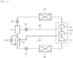
Fig. 1 , the air conditioner according to the related art includes acompressor 10 including afirst compression part 12, asecond compression part 14, and athird compression part 16. - A refrigerant discharged from the
compressor 10 passes through afirst expansion unit 30 via acondenser 20. The refrigerant passing through thefirst expansion unit 30 inflows into aphase separator 40. The refrigerant inflowing into thephase separator 40 is in a state in which a liquid refrigerant and a gaseous refrigerant are mixed with each other, and also is separated into the liquid refrigerant and the gaseous refrigerant by passing through thephase separator 40. Thephase separator 40 discharges the separated gaseous refrigerant into a separate tube. Also, the refrigerating in which the liquid refrigerant remaining after the gaseous refrigerant is separated and the gaseous refrigerant are mixed with each other are discharged through a separate outflow part. - The separated gaseous refrigerant may flow toward a discharge part of the
second compression part 14 of thecompressor 10 through afirst injection tube 45. The refrigerant discharged from thesecond compression part 14 and the refrigerant introduced through thefirst injection tube 45 are mixed with each other to flow into thethird compression part 16. - A
first injection valve 42 is disposed in thefirst injection tube 45. Thefirst injection valve 42 may control the amount of refrigerant flowing into thefirst injection tube 45 according to a heating load of the air conditioner. - The liquid and gaseous refrigerants discharged from the
phase separator 40 flow into an internal heat-exchanger 50. The air conditioner may further include asecond injection tube 65 branched from a tube connected to the internal heat-exchanger 50. The refrigerant flowing into thesecond injection tube 65 may be heat-exchanged with the refrigerant discharged from thephase separator 40 while flowing into the internal heat-exchanger 50. - The
second injection tube 65 is connected to thecompressor 10. In detail, thesecond injection tube 65 is connected to the discharge part of thefirst compression part 12. Also, the refrigerant flowing into thesecond injection tube 65 is mixed with the refrigerant discharged from thefirst compression 12, and then the mixed refrigerant flows into thesecond compression part 14. - The refrigerant discharged from the
phase separator 40 is throttled while passing through asecond expansion valve 70, and the refrigerant passing through thesecond expansion valve 70 flows into anevaporator 80. The refrigerant evaporated in theevaporator 80 is introduced again into thecompressor 10 to form a heating cycle. - As described above and mentioned in
Patent Literature 1, in the air conditioner according to the related art, to inject the refrigerant into thecompressor 10 including the plurality of compression parts, thephase separator 40 and the internal heat-exchanger should be separately provided. Thus, the air conditioner may be complicated in structure and increased in manufacturing cost. - [Patent Literature 1]
EP2325578 A2 (LG ELECTRONICS INC [KR]), 25/05/2011 - Although not shown, the
phase separator 40 may be omitted and the internal heat-exchanger may be provided. In this case, the refrigerant may be injected into the compressor using two internal heat-exchangers. Similarly, in case where the two internal heat-exchangers are provided, the air conditioner may be complicated in structure and increased in manufacturing cost. - Embodiments provide an air conditioner which is capable of improving cooling or heating performance and efficiently utilizing an inner space.
- The invention provides an air conditioner including an internal heat-exchanger and a phase separator which are capable of being utilized during the cooling or heating.
- The invention is defined by an air conditioner according to
claim 1. - The details of one or more embodiments are set forth in the accompanying drawings and the description below. Other features will be apparent from the description and drawings, and from the claims.
-
-
Fig. 1 is a schematic view illustrating a refrigerant cycle of an air conditioner according to a related art. -
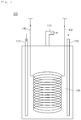
Fig. 2 is a view of a phase separator according to an embodiment. -
Fig. 3 is a view illustrating a connection relationship between a phase separator and a compressor according to an embodiment. -
Fig. 4 is a view illustrating a refrigerant flow during the heating in a refrigerant cycle in which a phase separator is applied according to an embodiment. -
Fig. 5 is a view illustrating a refrigerant flow during the cooling in a refrigerant cycle in which a phase separator is applied according to an embodiment. - Hereinafter, exemplary embodiments will be described with reference to the accompanying drawings.
- In the detailed description of the present application, a term an "inlet side" or "outlet side" may a term defined based on a flow direction of a refrigerant.
-
Fig. 2 is a view of a phase separator according to an embodiment.Fig. 3 is a view illustrating a connection relationship between a phase separator and a compressor according to an embodiment. - Referring to
Figs. 2 and3 , an air conditioner according to an embodiment includes acompressor 200 and aphase separator 100 for discharging a refrigerant to be injected into thecompressor 200. - In detail, the
compressor 200 includes first, second, andthird compression parts compressor 200 is compressed while successively passing through the first, second, andthird compression parts third compression part 206, the refrigerant is discharged from thecompressor 10. - The
phase separator 100 includes aninflow part 110 through which a refrigerant expanded through afirst expansion unit 210, agas separation part 130 through which a gaseous refrigerant separated from the refrigerant flowing into theinflow part 110 is discharged, and anoutflow part 120 through which the refrigerant flowing into theinflow part 110 and remaining after the gaseous refrigerant is separated is discharged. - The
first expansion unit 210 decompresses the refrigerant condensed by a condenser. The refrigerant has a two-phase state, i.e., a state in which the liquid refrigerant and the gaseous refrigerant are mixed with each other when the refrigerant is decompressed by thefirst expansion unit 210. - The gaseous refrigerant of the refrigerant introduced through the
inflow part 110 is discharged through thegas separation part 130. To easily discharge the gaseous refrigerant, thegas separation part 130 extends upward from a top surface of thephase separator 100. - A high
pressure injection passage 235 for guiding the gaseous refrigerant discharged from thegas separation part 130 to thecompressor 200 is disposed between thegas separation part 130 and thecompressor 200. - The high
pressure injection passage 235 is connected to a discharge side of thesecond compression part 204. The refrigerant flowing into the highpressure injection passage 235 is mixed with the refrigerant compressed by thesecond compression part 204 and flows into thethird compression part 206. A portion of thecompressor 200 connected to the highpressure injection passage 235 may be called a "high pressure part". - An
injection valve 230 for adjusting the amount of refrigerant to be injected into thecompressor 200 is disposed in the highpressure injection passage 235. An opening degree of theinjection valve 230 may be controlled based on the amount of refrigerant required according to the cooling or heating load. - The refrigerant introduced through the
inflow part 110 is cooled when the refrigerant is heat-exchanged in an internal heat-exchanger 145 and then discharged to the outside of thephase separator 100 through theoutflow part 120. - A
second expansion unit 220 for decompressing the refrigerant is disposed at the discharge side of theinflow part 120. The refrigerant discharged through theinflow part 120 flows into an evaporator after the refrigerant is expanded by thesecond expansion unit 220. - The
phase separator 100 includes afirst inflow tube 140 through which at least one portion of the refrigerant discharged through theoutflow part 120 is branched and flows and afirst outflow tube 150 for guiding the refrigerant introduced through thefirst inflow tube 140 to the outside of thephase separator 100. - The
first inflow tube 140 bypasses the refrigerant discharged from thephase separator 100 to flow again into thephase separator 100. Thus, thefirst inflow tube 140 may be called a "bypass part". Also, thefirst inflow tube 140 may extend inward from the outside of thephase separator 100. - A
third expansion unit 240 for expanding the refrigerant is disposed in thefirst inflow tube 140. The refrigerant bypassed into thefirst inflow tube 140 may be cooled while passing through thethird expansion unit 240 and flow into thephase separator 100. - The internal heat-
exchanger 145 communicating with thefirst inflow tube 140 and thefirst outflow tube 150 is disposed in an inner space of thephase separator 100. The refrigerant introduced through thefirst inflow tube 140 flows into thefirst outflow tube 150 via the internal heat-exchanger 145. - The internal heat-
exchanger 145 may have a structure which includes a tube through which a refrigerant flows and has a wide surface area to improve heat-exchange efficiency. For example, the internal heat-exchanger 145 may have a plurality of bent shapes such as a coil. - The refrigerant (hereinafter, referred to as a first refrigerant) introduced through the
inflow part 110 and the refrigerant (hereinafter, referred to as a second refrigerant) introduced through thefirst inflow tube 140 are heat-exchanged with each other in the internal heat-exchanger 145. In detail, the refrigerant introduced through theinflow part 110 is disposed at the outside of the tube of the internal heat-exchanger 145 in a state where the refrigerant is stored in thephase separator 100. Also, the refrigerant introduced through thefirst inflow tube 140 flows into the tube. Thus, the refrigerants may be heat-exchanged with each other. - When the first and second refrigerants are heat-exchanged with each other, the second refrigerant absorbs heat. As a result, at least one portion of the second refrigerant may be phase-changed in a gaseous state. The phase-changed gaseous refrigerant is discharged to the outside of the
phase separator 100 through thefirst outflow tube 150. Thefirst outflow tube 150 extends upward from the top surface of thephase separator 100. - A low
pressure injection passage 250 for guiding the refrigerant discharged through thefirst outflow tube 150 to thecompressor 200 is disposed between thephase separator 100 and thecompressor 200. The lowpressure injection passage 250 is connected to a discharge side of thefirst compression part 202. The refrigerant flowing into thecompressor 200 through the lowpressure injection passage 250 may be mixed with the refrigerant compressed by thefirst compression part 202 and flow into thesecond compression part 204. - A portion of the
compressor 200 connected to the lowpressure injection passage 250 may be called a "low pressure part". The refrigerant flowing into the lowpressure injection passage 250 may have a pressure less than that of the refrigerant flowing into the highpressure injection passage 235. - The amount of refrigerant injected through the low
pressure injection passage 250 may be adjusted by controlling an opening degree of thethird expansion unit 240. The opening degree of thethird expansion unit 240 may be adjusted based on the amount of refrigerant introduced through theinflow part 110 or a state of the refrigerant. - That is, since the heat-exchanged amount or heat-exchange efficiency in the internal heat-
exchanger 145 may be determined according to the amount (or the stored refrigerant amount) of refrigerant stored in thephase separator 100 or a state of the refrigerant, the amount of refrigerant to be injected into thecompressor 200 may be adjusted according to the stored refrigerant amount. - A refrigerant flow will be described below.
- The refrigerant decompressed by the
first expansion unit 210 is stored in thephase separator 100 through theinflow part 110 and heat-exchanged with the refrigerant flowing into the internal heat-exchanger 145. Then, the refrigerant is discharged through theoutflow part 120. The refrigerant discharged through theoutflow part 120 is decompressed by thesecond expansion unit 220 and flows into the evaporator. - At least one portion of the refrigerant discharged through the
outflow part 120 is expanded by thesecond expansion unit 240 and then flows into thephase separator 100 through thefirst inflow tube 140. Also, the refrigerant of thefirst inflow tube 140 flows into the internal heat-exchanger 145 and heat-exchanged with the refrigerant stored in thephase separator 100. Then, the refrigerant is discharged to the outside of thephase separator 100 through thefirst outflow tube 150. - The refrigerant discharged through the
first outflow tube 150 flows into the low pressure part of thecompressor 200 through the lowpressure injection passage 250. - The gaseous refrigerant of the two-phase refrigerant stored in the
phase separator 100 is discharged through thegas separation part 130 and injected into the high pressure part of thecompressor 200. - As described above, the refrigerant is injected into the
compressor 200 through the plurality ofinjection passages compressor 200. Here, the middle pressure may be greater than a suction pressure of thecompressor 200 and less than a discharge pressure of thecompressor 200. -
Fig. 4 is a view illustrating a refrigerant flow during the heating in a refrigerant cycle in which a phase separator is applied according to an embodiment.Fig. 5 is a view illustrating a refrigerant flow during the cooling in a refrigerant cycle in which a phase separator is applied according to an embodiment. - A refrigerant cycle of the air conditioner will be described with reference to
Fig. 4 . The air conditioner may include a four-way valve 320 for adjusting a flow direction of the refrigerant discharged from thecompressor 200 according to a cooling or heating operation, an outdoor heat-exchanger 330 in which indoor air is heat-exchanged with outdoor air in an indoor room, and anaccumulator 350 for temporarily storing the refrigerant flowing into thecompression 200. - A refrigerant passing through the condenser flows into the
phase separator 100 via thefirst expansion unit 210. In detail, when the air conditioner is operated in the cooling mode, the refrigerant passing through the outdoor heat-exchanger 330 flows into thephase separator 100. Also, when the air conditioner is operated in the heating mode, the refrigerant passing through the indoor heat-exchanger 340 may flow into thephase separator 100. - The air conditioner may further include a plurality of check valves and a plurality of connection passages which adjust the refrigerant flow so that the phase separation and the refrigerant injection into the compressor are realized during the cooling operation or the heating operation.
- In detail, the air conditioner includes a
first connection passage 312 connecting theoutflow part 120 to the indoor heat-exchanger 340 and afirst check valve 302 provided in thefirst connection passage 312. Thefirst check valve 302 is disposed in a passage defined between thesecond expansion unit 220 and the indoor heat-exchanger 340 to guide the refrigerant flow in one direction. - The air conditioner further includes a
second connection passage 314 branched from one point of the passage defined between thefirst check valve 302 and theindoor heat exchanger 340 and communicating with theinflow part 110. Asecond check valve 304 through which the refrigerant flows only toward theinflow part 110 is disposed in thesecond connection passage 314. - The air conditioner further includes a
third connection passage 316 through which the refrigerant flows from the outdoor heat-exchanger 330 into theinflow part 110. Athird check valve 306 through which the refrigerant flows from the outdoor heat-exchanger 330 into theinflow part 110 is disposed in thethird connection passage 316. - The air conditioner further includes a
fourth connection passage 318 branched from one point of the passage defined between thefirst check valve 302 and thesecond expansion unit 220 and communicating with thethird connection passage 316. Afourth check valve 308 through which the refrigerant flows from thefirst connection passage 312 into thethird connection passage 316 is disposed in thefourth connection passage 318. - A refrigerant flow in a refrigerant cycle when the air conditioner is operated in the heating mode will be described with reference to
Fig. 4 . - The refrigerant compressed by the
compressor 200 flows into the indoor heat-exchanger 340 via the four-way valve 320. The refrigerant condensed in the indoor heat-exchanger flows into thesecond connection passage 314. Here, thefirst check valve 302 prevents the refrigerant from flowing into thefirst connection passage 312. - The refrigerant flowing into the
second connection passage 314 is expanded by thefirst expansion unit 210 via thesecond check valve 304. The refrigerant passing through thefirst expansion unit 210 flows into thephase separator 100 through theinflow part 110. - The gaseous refrigerant separated by the
phase separator 100 is injected into the high pressure part of thecompressor 200 through the highpressure injection passage 235. The amount of refrigerant to be injected into the high pressure part may be adjusted by theinjection valve 230, and an opening degree of theinjection valve 230 of theinjection valve 230 may be adjusted according to a heating load. For example, when the heating load is large, the opening degree of theinjection valve 230 may be increased. - The gaseous and liquid refrigerants remaining in the
phase separator 100 without being separated is discharged through theoutflow part 120. At least one portion of the refrigerant discharged through theoutflow part 120 is bypassed into thefirst inflow tube 140 to flow into thephase separator 100. Then, the refrigerant is heat-exchanged with the refrigerant stored in thephase separator 100 in the internal heat-exchanger 145. - The refrigerant heated in the internal heat-
exchanger 145 is injected into the low pressure part of thecompressor 200 through the lowpressure injection passage 250. The amount of refrigerant injected into the low pressure part may be adjusted by thethird expansion unit 240. An opening degree of thethird expansion unit 240 may be adjusted according to a heating load. For example, when the heating load is large, the opening degree of thethird expansion unit 240 may be increased. - The refrigerant discharged through the
outflow part 120 is expanded by thesecond expansion unit 220 to flow into thefourth connection passage 318. - The refrigerant flows from the
first connection passage 312 into the indoor heat-exchanger 340 by thefirst check valve 302. However, since the refrigerant discharged from the indoor heat-exchanger 340 has a pressure greater than that of the refrigerant of an inlet side of thefirst check valve 302, the refrigerant passing through thesecond expansion unit 220 may flow into thefourth connection passage 318. - The refrigerant passing through the
fourth check valve 308 flows into the outdoor heat-exchanger 330 through thethird connection passage 316. - The refrigerant may flow from the
third connection passage 316 into theinflow part 110 by thethird check valve 306. However, since the refrigerant of an inflow part side has a pressure greater than that of the inlet side of the outdoor heat-exchanger 330, the refrigerant may flow into the outdoor heat-exchanger 330 via thefourth check valve 308 and thethird connection passage 316. - The refrigerant is evaporated in the outdoor heat-
exchanger 330, and the refrigerant passing through the outdoor heat-exchanger 330 flows into theaccumulator 350 via the four-way valve 320. The gaseous refrigerant of the refrigerant stored in theaccumulator 350 flows into thecompressor 200. This refrigerant cycle may be repeatedly performed. - A refrigerant flow in a refrigerant cycle when the air conditioner is operated in the cooling mode will be described with reference to
Fig. 5 . - The refrigerant compressed by the
compressor 200 flows into the outdoor heat-exchanger 330 via the four-way valve 320. The condensed refrigerant passing through the outdoor heat-exchanger 330 flows into thethird connection passage 316. The refrigerant flowing into thethird connection passage 316 flows into theinflow part 110 via thethird check valve 306 and thefirst expansion unit 210. - The refrigerant flowing into the
third connection passage 316 does not flow into thesecond connection passage 314 and thefourth connection passage 318 by thefourth check valve 308, respectively. - The refrigerant flowing into the
inflow part 110 passes through thephase separator 100. Since a flow of the refrigerant injected from thephase separator 100 into thecompressor 200 is equal to that ofFig. 4 , its description will be omitted. - The refrigerant discharged from the
outflow part 150 flows into thefirst connection passage 312 via thesecond expansion unit 220 and flows into the indoor heat-exchanger 340 via thefirst check valve 302. - Since the refrigerant flowing into the
third connection part 316 has a pressure greater than that of the refrigerant flowing into thefirst connection passage 312, the inflow of the refrigerant into thesecond connection passage 314 and thefourth connection passage 318 may be limited. The refrigerant passing through thefirst connection passage 312 flows into the indoor heat-exchanger 340. - The refrigerant evaporated in the indoor heat-
exchanger 340 flows into theaccumulator 350 via the four-way valve 320. The gaseous refrigerant of the refrigerant stored in theaccumulator 350 flows into thecompressor 200. This refrigerant cycle may be repeatedly performed. - According to the proposed embodiment, since the refrigerant is injected into the compressor including the multiple stage compression parts, the circulation amount of refrigerant may be increased to improve the cooling or heating performance.
- Also, the internal heat-exchanger may be disposed within the phase separator to improve the gas and liquid separation performance. Also, since the phase separator and the internal heat-exchanger may not be separately provided, the assembly of the air conditioner may be improved and also the compact air conditioner may be realized.
Claims (7)
- An air conditioner comprising a compressor (200) for compressing a refrigerant;
a condenser (340) for condensing the refrigerant compressed by the compressor;
a phase separator (100) for separating a gaseous refrigerant from the refrigerant passing through the condenser;
an evaporator (330) for evaporating the refrigerant passing through the phase separator;
an inflow part (110) provided in the phase separator to introduce the refrigerant into the phase separator;
a gas separation part (130) configured to discharge the gaseous refrigerant separated by the phase separator;
an injection passage (235,250) configured to inject the refrigerant discharged from the phase separator into the compressor; and
an internal heat-exchanger (145) provided within the phase separator to heat-exchange a refrigerant therein with the refrigerant introduced through the inflow part;
an outflow part (120) provided in the phase separator to discharge the refrigerant introduced through the inflow part after the refrigerant introduced through the inflow part is heat-exchanged with the refrigerant within the internal heat-exchanger;
a first inflow tube (140) bypassing the refrigerant discharged from the outflow part to introduce the discharged refrigerant into the phase separator;
a first outflow tube (150) discharging the refrigerant introduced through the first inflow tube to the outside of the phase separator; wherein
the injection passage (235, 250) comprises a low pressure injection passage (250) for guiding injection of the refrigerant discharged through the first outflow tube into the compressor; and
a high pressure injection passage (235) for guiding injection of the refrigerant discharged through the gas separation part so that the refrigerant is injected into a high pressure part of the compressor, wherein:the compressor comprises a first compression part (202) for compressing the refrigerant passing through the evaporator,a second compression part (204) for compressing the refrigerant compressed by the first compression part, anda third compression part (206) for compressing the refrigerant compressed by the second compression part, characterized in that:the refrigerant discharged from the gas separation part flows into between the second compression part and the third compression part and the refrigerant discharged through the first outflow tube flows into between the first compression part and the second compression part,the condenser or the evaporator is an indoor heat-exchanger, and the air conditioner further comprises:a first connection passage (312) connecting the outflow part to the indoor heat-exchanger;a first check valve (302) provided in the first connection passage to guide the refrigerant in one direction;a second connection passage (314) branched from one point of a passage defined between the first check valve and the indoor heat-exchanger to communicate with the inflow part; anda second check valve (304) provided in the second connection passage to guide a refrigerant flow in a direction of the inflow part. - The air conditioner according to claim 1, wherein the first inflow tube (140) and the first outflow tube (150) communicate with the internal heat-exchanger (145).
- The air conditioner according to claim 1, wherein the refrigerant introduced through the first inflow tube (140) flows into the internal heat-exchanger (145) and is heat-exchanged with the refrigerant introduced through the inflow part (110).
- The air conditioner according to claim 1, further comprising:a first expansion unit (210) provided at an inlet side of the inflow part to expand a refrigerant to be introduced into the phase separator (100); anda second expansion unit (220) provided at an outlet side of the outflow part to expand a refrigerant.
- The air conditioner according to claim 1, further comprising:
a third expansion unit (240) provided in the first inflow tube (140) to expand a refrigerant to be introduced into the phase separator (100) through the first inflow tube (140). - The air conditioner according to claim 1, wherein the other one of the condenser or the evaporator (330) is an outdoor heat-exchanger, and
the air conditioner further comprises:a third connection passage (316) configured to introduce a refrigerant from the outdoor heat-exchanger into the inflow part; anda third check valve (306) provided in the third connection passage to guide the refrigerant flow from the outdoor heat-exchanger toward the inflow part. - The air conditioner according to claim 6, further comprising:a fourth connection passage (318) branched from one point of the first connection passage to communicate with the third connection passage; anda fourth check valve (308) provided in the fourth connection passage (318) to introduce a refrigerant from the first connection passage (312) toward the third connection passage(316).
Applications Claiming Priority (1)
| Application Number | Priority Date | Filing Date | Title |
|---|---|---|---|
| KR1020110089982A KR101288681B1 (en) | 2011-09-06 | 2011-09-06 | Air conditioner |
Publications (3)
| Publication Number | Publication Date |
|---|---|
| EP2568232A2 EP2568232A2 (en) | 2013-03-13 |
| EP2568232A3 EP2568232A3 (en) | 2015-03-04 |
| EP2568232B1 true EP2568232B1 (en) | 2020-04-29 |
Family
ID=45999590
Family Applications (1)
| Application Number | Title | Priority Date | Filing Date |
|---|---|---|---|
| EP12160718.8A Active EP2568232B1 (en) | 2011-09-06 | 2012-03-22 | Air conditioner |
Country Status (3)
| Country | Link |
|---|---|
| US (1) | US20130055754A1 (en) |
| EP (1) | EP2568232B1 (en) |
| KR (1) | KR101288681B1 (en) |
Families Citing this family (9)
| Publication number | Priority date | Publication date | Assignee | Title |
|---|---|---|---|---|
| KR102242777B1 (en) * | 2014-03-20 | 2021-04-20 | 엘지전자 주식회사 | Air Conditioner |
| WO2015198475A1 (en) * | 2014-06-27 | 2015-12-30 | 三菱電機株式会社 | Refrigeration cycle device |
| KR101702736B1 (en) * | 2015-01-12 | 2017-02-03 | 엘지전자 주식회사 | An air conditioner |
| CN108507240A (en) * | 2015-11-11 | 2018-09-07 | 成都睿达致祥科技有限公司 | A kind of working method of air-conditioning device |
| KR101911261B1 (en) * | 2016-11-21 | 2018-12-19 | 엘지전자 주식회사 | Air conditioner |
| KR102106003B1 (en) * | 2018-02-09 | 2020-04-29 | 엘지전자 주식회사 | An air conditioner |
| KR20200061005A (en) | 2018-11-23 | 2020-06-02 | 엘지전자 주식회사 | Air conditioner |
| CN109974349B (en) * | 2019-03-05 | 2020-04-24 | 中国科学院力学研究所 | Jet flow self-cooling device |
| JP2022181836A (en) * | 2021-05-27 | 2022-12-08 | 三菱重工サーマルシステムズ株式会社 | Multistage compression refrigeration device |
Family Cites Families (12)
| Publication number | Priority date | Publication date | Assignee | Title |
|---|---|---|---|---|
| JPS60261A (en) * | 1983-06-17 | 1985-01-05 | 株式会社日立製作所 | Refrigeration cycle |
| JPH07127926A (en) * | 1993-11-05 | 1995-05-19 | Kubota Corp | Gas-liquid separator in compression type heat pump |
| US5692389A (en) * | 1996-06-28 | 1997-12-02 | Carrier Corporation | Flash tank economizer |
| US5996360A (en) * | 1997-11-27 | 1999-12-07 | Denso Corporation | Refrigerant cycle system |
| US6959557B2 (en) * | 2003-09-02 | 2005-11-01 | Tecumseh Products Company | Apparatus for the storage and controlled delivery of fluids |
| US7299649B2 (en) * | 2003-12-09 | 2007-11-27 | Emerson Climate Technologies, Inc. | Vapor injection system |
| JP2005226972A (en) | 2004-02-16 | 2005-08-25 | Denso Corp | Refrigerating apparatus |
| US20060225459A1 (en) * | 2005-04-08 | 2006-10-12 | Visteon Global Technologies, Inc. | Accumulator for an air conditioning system |
| JP4899489B2 (en) * | 2006-01-19 | 2012-03-21 | ダイキン工業株式会社 | Refrigeration equipment |
| KR100784610B1 (en) | 2006-08-17 | 2007-12-11 | 주식회사 두원공조 | Accumulator combined with internal heat exchanger of air conditioner |
| JP4245064B2 (en) * | 2007-05-30 | 2009-03-25 | ダイキン工業株式会社 | Air conditioner |
| KR101155494B1 (en) * | 2009-11-18 | 2012-06-15 | 엘지전자 주식회사 | Heat pump |
-
2011
- 2011-09-06 KR KR1020110089982A patent/KR101288681B1/en active IP Right Grant
-
2012
- 2012-03-22 EP EP12160718.8A patent/EP2568232B1/en active Active
- 2012-03-26 US US13/430,366 patent/US20130055754A1/en not_active Abandoned
Non-Patent Citations (1)
| Title |
|---|
| None * |
Also Published As
| Publication number | Publication date |
|---|---|
| US20130055754A1 (en) | 2013-03-07 |
| EP2568232A2 (en) | 2013-03-13 |
| EP2568232A3 (en) | 2015-03-04 |
| KR20130026674A (en) | 2013-03-14 |
| KR101288681B1 (en) | 2013-07-22 |
Similar Documents
| Publication | Publication Date | Title |
|---|---|---|
| EP2568232B1 (en) | Air conditioner | |
| EP2325578B1 (en) | Heat pump | |
| US9612042B2 (en) | Method of operating a refrigeration system in a null cycle | |
| EP2325577B1 (en) | Heat pump | |
| EP2924370B1 (en) | Air conditioner and method for controlling an air conditioner | |
| EP2381180B1 (en) | Heat pump type hot water supply apparatus | |
| JP5698160B2 (en) | Air conditioner | |
| KR101212681B1 (en) | air conditioner | |
| US7802440B2 (en) | Compression system and air conditioning system | |
| KR101319778B1 (en) | Air conditioner | |
| US20060123834A1 (en) | Air conditioner | |
| EP2587189B1 (en) | Air conditioner | |
| US20110192181A1 (en) | Refrigerant system | |
| EP3144606B1 (en) | Air conditioner | |
| KR101288745B1 (en) | Air conditioner | |
| KR101161381B1 (en) | Refrigerant cycle apparatus | |
| US11519645B2 (en) | Air conditioning apparatus | |
| KR101303483B1 (en) | Air conditioner | |
| JP2001056156A (en) | Air conditioning apparatus | |
| EP3578898B1 (en) | Outdoor unit for air conditioner | |
| CN114402171A (en) | Heat pump | |
| JP5062079B2 (en) | Refrigeration equipment | |
| EP3150939B1 (en) | Air conditioner system | |
| KR100488532B1 (en) | Cooling system | |
| KR101416933B1 (en) | Air conditioning system |
Legal Events
| Date | Code | Title | Description |
|---|---|---|---|
| PUAI | Public reference made under article 153(3) epc to a published international application that has entered the european phase |
Free format text: ORIGINAL CODE: 0009012 |
|
| 17P | Request for examination filed |
Effective date: 20120322 |
|
| AK | Designated contracting states |
Kind code of ref document: A2 Designated state(s): AL AT BE BG CH CY CZ DE DK EE ES FI FR GB GR HR HU IE IS IT LI LT LU LV MC MK MT NL NO PL PT RO RS SE SI SK SM TR |
|
| AX | Request for extension of the european patent |
Extension state: BA ME |
|
| PUAL | Search report despatched |
Free format text: ORIGINAL CODE: 0009013 |
|
| AK | Designated contracting states |
Kind code of ref document: A3 Designated state(s): AL AT BE BG CH CY CZ DE DK EE ES FI FR GB GR HR HU IE IS IT LI LT LU LV MC MK MT NL NO PL PT RO RS SE SI SK SM TR |
|
| AX | Request for extension of the european patent |
Extension state: BA ME |
|
| RIC1 | Information provided on ipc code assigned before grant |
Ipc: F25B 40/00 20060101ALI20150129BHEP Ipc: F25B 1/10 20060101AFI20150129BHEP |
|
| RBV | Designated contracting states (corrected) |
Designated state(s): AL AT BE BG CH CY CZ DE DK EE ES FI FR GB GR HR HU IE IS IT LI LT LU LV MC MK MT NL NO PL PT RO RS SE SI SK SM TR |
|
| STAA | Information on the status of an ep patent application or granted ep patent |
Free format text: STATUS: EXAMINATION IS IN PROGRESS |
|
| 17Q | First examination report despatched |
Effective date: 20180815 |
|
| REG | Reference to a national code |
Ref country code: DE Ref legal event code: R079 Ref document number: 602012069623 Country of ref document: DE Free format text: PREVIOUS MAIN CLASS: F25B0001100000 Ipc: F25B0013000000 |
|
| GRAP | Despatch of communication of intention to grant a patent |
Free format text: ORIGINAL CODE: EPIDOSNIGR1 |
|
| STAA | Information on the status of an ep patent application or granted ep patent |
Free format text: STATUS: GRANT OF PATENT IS INTENDED |
|
| RIC1 | Information provided on ipc code assigned before grant |
Ipc: F25B 13/00 20060101AFI20191113BHEP Ipc: F25B 1/10 20060101ALI20191113BHEP Ipc: F25B 40/00 20060101ALI20191113BHEP |
|
| INTG | Intention to grant announced |
Effective date: 20191127 |
|
| GRAS | Grant fee paid |
Free format text: ORIGINAL CODE: EPIDOSNIGR3 |
|
| GRAA | (expected) grant |
Free format text: ORIGINAL CODE: 0009210 |
|
| STAA | Information on the status of an ep patent application or granted ep patent |
Free format text: STATUS: THE PATENT HAS BEEN GRANTED |
|
| RAP1 | Party data changed (applicant data changed or rights of an application transferred) |
Owner name: LG ELECTRONICS INC. |
|
| AK | Designated contracting states |
Kind code of ref document: B1 Designated state(s): AL AT BE BG CH CY CZ DE DK EE ES FI FR GB GR HR HU IE IS IT LI LT LU LV MC MK MT NL NO PL PT RO RS SE SI SK SM TR |
|
| REG | Reference to a national code |
Ref country code: GB Ref legal event code: FG4D |
|
| REG | Reference to a national code |
Ref country code: CH Ref legal event code: EP |
|
| REG | Reference to a national code |
Ref country code: AT Ref legal event code: REF Ref document number: 1263928 Country of ref document: AT Kind code of ref document: T Effective date: 20200515 |
|
| REG | Reference to a national code |
Ref country code: DE Ref legal event code: R096 Ref document number: 602012069623 Country of ref document: DE |
|
| REG | Reference to a national code |
Ref country code: IE Ref legal event code: FG4D |
|
| REG | Reference to a national code |
Ref country code: NL Ref legal event code: MP Effective date: 20200429 |
|
| REG | Reference to a national code |
Ref country code: LT Ref legal event code: MG4D |
|
| PG25 | Lapsed in a contracting state [announced via postgrant information from national office to epo] |
Ref country code: NO Free format text: LAPSE BECAUSE OF FAILURE TO SUBMIT A TRANSLATION OF THE DESCRIPTION OR TO PAY THE FEE WITHIN THE PRESCRIBED TIME-LIMIT Effective date: 20200729 Ref country code: LT Free format text: LAPSE BECAUSE OF FAILURE TO SUBMIT A TRANSLATION OF THE DESCRIPTION OR TO PAY THE FEE WITHIN THE PRESCRIBED TIME-LIMIT Effective date: 20200429 Ref country code: SE Free format text: LAPSE BECAUSE OF FAILURE TO SUBMIT A TRANSLATION OF THE DESCRIPTION OR TO PAY THE FEE WITHIN THE PRESCRIBED TIME-LIMIT Effective date: 20200429 Ref country code: GR Free format text: LAPSE BECAUSE OF FAILURE TO SUBMIT A TRANSLATION OF THE DESCRIPTION OR TO PAY THE FEE WITHIN THE PRESCRIBED TIME-LIMIT Effective date: 20200730 Ref country code: PT Free format text: LAPSE BECAUSE OF FAILURE TO SUBMIT A TRANSLATION OF THE DESCRIPTION OR TO PAY THE FEE WITHIN THE PRESCRIBED TIME-LIMIT Effective date: 20200831 Ref country code: IS Free format text: LAPSE BECAUSE OF FAILURE TO SUBMIT A TRANSLATION OF THE DESCRIPTION OR TO PAY THE FEE WITHIN THE PRESCRIBED TIME-LIMIT Effective date: 20200829 Ref country code: FI Free format text: LAPSE BECAUSE OF FAILURE TO SUBMIT A TRANSLATION OF THE DESCRIPTION OR TO PAY THE FEE WITHIN THE PRESCRIBED TIME-LIMIT Effective date: 20200429 |
|
| REG | Reference to a national code |
Ref country code: AT Ref legal event code: MK05 Ref document number: 1263928 Country of ref document: AT Kind code of ref document: T Effective date: 20200429 |
|
| PG25 | Lapsed in a contracting state [announced via postgrant information from national office to epo] |
Ref country code: HR Free format text: LAPSE BECAUSE OF FAILURE TO SUBMIT A TRANSLATION OF THE DESCRIPTION OR TO PAY THE FEE WITHIN THE PRESCRIBED TIME-LIMIT Effective date: 20200429 Ref country code: LV Free format text: LAPSE BECAUSE OF FAILURE TO SUBMIT A TRANSLATION OF THE DESCRIPTION OR TO PAY THE FEE WITHIN THE PRESCRIBED TIME-LIMIT Effective date: 20200429 Ref country code: BG Free format text: LAPSE BECAUSE OF FAILURE TO SUBMIT A TRANSLATION OF THE DESCRIPTION OR TO PAY THE FEE WITHIN THE PRESCRIBED TIME-LIMIT Effective date: 20200729 Ref country code: RS Free format text: LAPSE BECAUSE OF FAILURE TO SUBMIT A TRANSLATION OF THE DESCRIPTION OR TO PAY THE FEE WITHIN THE PRESCRIBED TIME-LIMIT Effective date: 20200429 |
|
| PG25 | Lapsed in a contracting state [announced via postgrant information from national office to epo] |
Ref country code: AL Free format text: LAPSE BECAUSE OF FAILURE TO SUBMIT A TRANSLATION OF THE DESCRIPTION OR TO PAY THE FEE WITHIN THE PRESCRIBED TIME-LIMIT Effective date: 20200429 Ref country code: NL Free format text: LAPSE BECAUSE OF FAILURE TO SUBMIT A TRANSLATION OF THE DESCRIPTION OR TO PAY THE FEE WITHIN THE PRESCRIBED TIME-LIMIT Effective date: 20200429 |
|
| PG25 | Lapsed in a contracting state [announced via postgrant information from national office to epo] |
Ref country code: ES Free format text: LAPSE BECAUSE OF FAILURE TO SUBMIT A TRANSLATION OF THE DESCRIPTION OR TO PAY THE FEE WITHIN THE PRESCRIBED TIME-LIMIT Effective date: 20200429 Ref country code: AT Free format text: LAPSE BECAUSE OF FAILURE TO SUBMIT A TRANSLATION OF THE DESCRIPTION OR TO PAY THE FEE WITHIN THE PRESCRIBED TIME-LIMIT Effective date: 20200429 Ref country code: CZ Free format text: LAPSE BECAUSE OF FAILURE TO SUBMIT A TRANSLATION OF THE DESCRIPTION OR TO PAY THE FEE WITHIN THE PRESCRIBED TIME-LIMIT Effective date: 20200429 Ref country code: RO Free format text: LAPSE BECAUSE OF FAILURE TO SUBMIT A TRANSLATION OF THE DESCRIPTION OR TO PAY THE FEE WITHIN THE PRESCRIBED TIME-LIMIT Effective date: 20200429 Ref country code: EE Free format text: LAPSE BECAUSE OF FAILURE TO SUBMIT A TRANSLATION OF THE DESCRIPTION OR TO PAY THE FEE WITHIN THE PRESCRIBED TIME-LIMIT Effective date: 20200429 Ref country code: SM Free format text: LAPSE BECAUSE OF FAILURE TO SUBMIT A TRANSLATION OF THE DESCRIPTION OR TO PAY THE FEE WITHIN THE PRESCRIBED TIME-LIMIT Effective date: 20200429 Ref country code: IT Free format text: LAPSE BECAUSE OF FAILURE TO SUBMIT A TRANSLATION OF THE DESCRIPTION OR TO PAY THE FEE WITHIN THE PRESCRIBED TIME-LIMIT Effective date: 20200429 Ref country code: DK Free format text: LAPSE BECAUSE OF FAILURE TO SUBMIT A TRANSLATION OF THE DESCRIPTION OR TO PAY THE FEE WITHIN THE PRESCRIBED TIME-LIMIT Effective date: 20200429 |
|
| REG | Reference to a national code |
Ref country code: DE Ref legal event code: R097 Ref document number: 602012069623 Country of ref document: DE |
|
| PG25 | Lapsed in a contracting state [announced via postgrant information from national office to epo] |
Ref country code: SK Free format text: LAPSE BECAUSE OF FAILURE TO SUBMIT A TRANSLATION OF THE DESCRIPTION OR TO PAY THE FEE WITHIN THE PRESCRIBED TIME-LIMIT Effective date: 20200429 Ref country code: PL Free format text: LAPSE BECAUSE OF FAILURE TO SUBMIT A TRANSLATION OF THE DESCRIPTION OR TO PAY THE FEE WITHIN THE PRESCRIBED TIME-LIMIT Effective date: 20200429 |
|
| PLBE | No opposition filed within time limit |
Free format text: ORIGINAL CODE: 0009261 |
|
| STAA | Information on the status of an ep patent application or granted ep patent |
Free format text: STATUS: NO OPPOSITION FILED WITHIN TIME LIMIT |
|
| 26N | No opposition filed |
Effective date: 20210201 |
|
| PG25 | Lapsed in a contracting state [announced via postgrant information from national office to epo] |
Ref country code: SI Free format text: LAPSE BECAUSE OF FAILURE TO SUBMIT A TRANSLATION OF THE DESCRIPTION OR TO PAY THE FEE WITHIN THE PRESCRIBED TIME-LIMIT Effective date: 20200429 |
|
| PG25 | Lapsed in a contracting state [announced via postgrant information from national office to epo] |
Ref country code: MC Free format text: LAPSE BECAUSE OF FAILURE TO SUBMIT A TRANSLATION OF THE DESCRIPTION OR TO PAY THE FEE WITHIN THE PRESCRIBED TIME-LIMIT Effective date: 20200429 |
|
| REG | Reference to a national code |
Ref country code: CH Ref legal event code: PL |
|
| GBPC | Gb: european patent ceased through non-payment of renewal fee |
Effective date: 20210322 |
|
| REG | Reference to a national code |
Ref country code: BE Ref legal event code: MM Effective date: 20210331 |
|
| PG25 | Lapsed in a contracting state [announced via postgrant information from national office to epo] |
Ref country code: GB Free format text: LAPSE BECAUSE OF NON-PAYMENT OF DUE FEES Effective date: 20210322 Ref country code: IE Free format text: LAPSE BECAUSE OF NON-PAYMENT OF DUE FEES Effective date: 20210322 Ref country code: FR Free format text: LAPSE BECAUSE OF NON-PAYMENT OF DUE FEES Effective date: 20210331 Ref country code: CH Free format text: LAPSE BECAUSE OF NON-PAYMENT OF DUE FEES Effective date: 20210331 Ref country code: LU Free format text: LAPSE BECAUSE OF NON-PAYMENT OF DUE FEES Effective date: 20210322 Ref country code: LI Free format text: LAPSE BECAUSE OF NON-PAYMENT OF DUE FEES Effective date: 20210331 |
|
| PG25 | Lapsed in a contracting state [announced via postgrant information from national office to epo] |
Ref country code: BE Free format text: LAPSE BECAUSE OF NON-PAYMENT OF DUE FEES Effective date: 20210331 |
|
| PG25 | Lapsed in a contracting state [announced via postgrant information from national office to epo] |
Ref country code: HU Free format text: LAPSE BECAUSE OF FAILURE TO SUBMIT A TRANSLATION OF THE DESCRIPTION OR TO PAY THE FEE WITHIN THE PRESCRIBED TIME-LIMIT; INVALID AB INITIO Effective date: 20120322 Ref country code: CY Free format text: LAPSE BECAUSE OF FAILURE TO SUBMIT A TRANSLATION OF THE DESCRIPTION OR TO PAY THE FEE WITHIN THE PRESCRIBED TIME-LIMIT Effective date: 20200429 |
|
| PGFP | Annual fee paid to national office [announced via postgrant information from national office to epo] |
Ref country code: DE Payment date: 20230206 Year of fee payment: 12 |