EP2568190A2 - Flexible diaphragm coupling for axial force loading - Google Patents
Flexible diaphragm coupling for axial force loading Download PDFInfo
- Publication number
- EP2568190A2 EP2568190A2 EP12183470A EP12183470A EP2568190A2 EP 2568190 A2 EP2568190 A2 EP 2568190A2 EP 12183470 A EP12183470 A EP 12183470A EP 12183470 A EP12183470 A EP 12183470A EP 2568190 A2 EP2568190 A2 EP 2568190A2
- Authority
- EP
- European Patent Office
- Prior art keywords
- diaphragm
- flexible
- axial thickness
- coupling
- radially
- Prior art date
- Legal status (The legal status is an assumption and is not a legal conclusion. Google has not performed a legal analysis and makes no representation as to the accuracy of the status listed.)
- Granted
Links
Images

Classifications
-
- F—MECHANICAL ENGINEERING; LIGHTING; HEATING; WEAPONS; BLASTING
- F16—ENGINEERING ELEMENTS AND UNITS; GENERAL MEASURES FOR PRODUCING AND MAINTAINING EFFECTIVE FUNCTIONING OF MACHINES OR INSTALLATIONS; THERMAL INSULATION IN GENERAL
- F16D—COUPLINGS FOR TRANSMITTING ROTATION; CLUTCHES; BRAKES
- F16D3/00—Yielding couplings, i.e. with means permitting movement between the connected parts during the drive
- F16D3/50—Yielding couplings, i.e. with means permitting movement between the connected parts during the drive with the coupling parts connected by one or more intermediate members
- F16D3/72—Yielding couplings, i.e. with means permitting movement between the connected parts during the drive with the coupling parts connected by one or more intermediate members with axially-spaced attachments to the coupling parts
-
- F—MECHANICAL ENGINEERING; LIGHTING; HEATING; WEAPONS; BLASTING
- F16—ENGINEERING ELEMENTS AND UNITS; GENERAL MEASURES FOR PRODUCING AND MAINTAINING EFFECTIVE FUNCTIONING OF MACHINES OR INSTALLATIONS; THERMAL INSULATION IN GENERAL
- F16D—COUPLINGS FOR TRANSMITTING ROTATION; CLUTCHES; BRAKES
- F16D3/00—Yielding couplings, i.e. with means permitting movement between the connected parts during the drive
- F16D3/50—Yielding couplings, i.e. with means permitting movement between the connected parts during the drive with the coupling parts connected by one or more intermediate members
- F16D3/78—Yielding couplings, i.e. with means permitting movement between the connected parts during the drive with the coupling parts connected by one or more intermediate members shaped as an elastic disc or flat ring, arranged perpendicular to the axis of the coupling parts, different sets of spots of the disc or ring being attached to each coupling part, e.g. Hardy couplings
- F16D3/79—Yielding couplings, i.e. with means permitting movement between the connected parts during the drive with the coupling parts connected by one or more intermediate members shaped as an elastic disc or flat ring, arranged perpendicular to the axis of the coupling parts, different sets of spots of the disc or ring being attached to each coupling part, e.g. Hardy couplings the disc or ring being metallic
Definitions
- the subject invention is directed to flexible couplings, and more particularly to a flexible diaphragm coupling for rotating shaft components, which is configured to tolerate axial forces and the axial bending stress distribution associated therewith.
- Flexible couplings for connecting two rotating shafts to one another, to transmit torque while accommodating axial and/or angular misalignment of the shafts have been used in aerospace applications for many years. These devices often use one or more contoured diaphragms welded or otherwise secured together to form a flexible coupling mounted between driving and driven shaft components.
- the subject invention is directed to a new and useful flexible diaphragm coupling for supporting rotating shaft couplings, which is adapted and configured to accommodate a total axial force load and the axial bending stress distributions associated therewith. More particularly, the geometric configuration of the diaphragm coupling of the subject invention is optimized to accommodate the stress distribution associated with linear and cubic non-linear restorative spring forces generated by an axially applied load.
- the novel diaphragm coupling includes a radially inner hub portion defining a central axis, a radially outer rim portion, and a flexible diaphragm portion that extends between the radially outer rim portion and the radially inner hub portion.
- the flexible diaphragm portion includes a radially inner diaphragm section having a maximum axial thickness adjacent the radially inner hub portion and a radially outwardly tapering axial thickness extending to a point of minimum axial thickness of the diaphragm portion, and a radially outer diaphragm section having a maximum axial thickness adjacent the radially outer rim portion and a radially inwardly tapering axial thickness extending to the point of minimum axial thickness of the diaphragm portion.
- the point of minimum axial thickness of the diaphragm portion is closer to the radially outer rim portion than to the radially inner hub portion.
- the maximum axial thickness of the radially inner diaphragm section is greater than the maximum axial thickness of the radially outer diaphragm section.
- the diaphragm portion includes axially opposed first and second side surfaces. In one embodiment of the invention, the first side surface of the diaphragm portion is contoured and the second side surface is planar. In an alternative embodiment, the first and second side surfaces of the diaphragm portion are contoured.
- the diaphragm coupling is formed integral with another flexible element.
- the flexible element may be selected from a group consisting of a spline, a bolted flange or another flexible diaphragm.
- the flexible element may be connected to the radially outer rim portion of the diaphragm coupling, or to the radially inner hub portion of the diaphragm coupling.
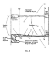
- Diaphragm element 10 includes a radially inner annular hub portion 12, a radially outer annular rim portion 14, and a flexible diaphragm portion 16 that extends between the radially outer rim portion 14 and the radially inner hub portion 12.
- the flexible diaphragm portion 16 includes a radially inner diaphragm section 18 having a maximum axial thickness TBF adjacent the radially inner hub portion 12 and a radially outwardly tapering axial thickness extending to a point of minimum axial thickness T min of the diaphragm portion 16.
- the flexible diaphragm portion 16 further includes a radially outer diaphragm section 20 having a maximum axial thickness TA adjacent the radially outer rim portion 14 and a radially inwardly tapering axial thickness extending to the point of minimum axial thickness T min of the diaphragm portion 16.
- the maximum axial thickness TBF adjacent the radially inner hub portion 12 should be 2.86 times the maximum axial thickness TA adjacent the radially outer rim portion 14. It has also been determined through analytical mathematics that the point of minimum axial thickness T min of the diaphragm portion 16 must be closer to the radially outer rim portion 14 than to the radially inner hub portion 12, to best accommodate the stress distribution resulting from axial loading. It is envisioned that the proximity of the point of minimum axial thickness T min to the radially outer rim portion 14 could vary within a range of about 20%, while maintaining the requisite stiffness characteristics of the diaphragm element. Furthermore, the contoured profile of the diaphragm element 10 accounts for the torque transmission requirements and buckling stability of the coupling.
- the diaphragm portion 16 includes axially opposed first and second side surfaces 22, 24.
- first side surface 22 is contoured and the second side surface 24 is planar.
- both the first side surface and the second side surface of the diaphragm element can be contoured.
- the prior art diaphragm coupling element 100 includes a contoured diaphragm section 116 with a point of minimum axial thickness T min located at the midpoint of the diaphragm portion 116.
- T min minimum axial thickness
- the taper thickness ratio (TBF/TA) of the diaphragm coupling element 10 of the subject invention should increase by at least about 10% relative to the taper thickness ratio of the prior art diaphragm coupling 100. Therefore, if the taper thickness ratio of the prior art diaphragm coupling element 100 is about 1.00, then the taper thickness ratio for the diaphragm coupling element 10 of the subject invention would be about 1.10.
- the diaphragm coupling element 10 of the subject invention can be formed integral with another flexible element.
- the flexible element can be selected from a group consisting of a spline, a bolted flange or another flexible diaphragm element 10.
- the other flexible element can be connected to the radially outer rim portion of the diaphragm coupling, or to the radially inner hub portion of the diaphragm coupling, depending upon the type of shaft components and/or application with which the coupling is employed.
- Fig. 2 illustrates a diaphragm coupling assembly designated generally by reference numeral 200 in which a plurality of flexible diaphragm coupling elements constructed in accordance with subject invention are employed to provide a flexible junction between two rotating drive shaft components.
- the coupling assembly 200 includes a first flange portion 202 for mating with a first shaft component (not shown) and a second flange portion 204 for mating with a second shaft component (not shown).
- the first and second flange portions 202, 204 are connected to one another by four axially aligned flexible diaphragm coupling elements, including a first flexible diaphragm element 210, a second flexible diaphragm element 212, a third flexible diaphragm element 214 and a fourth flexible diaphragm element 216.
- Coupling assembly 200 includes two inverted pairs of axially aligned diaphragm elements. That is, the first and second diaphragm elements 210 and 212 are aligned so that the countered surfaces thereof face toward the first flange portion 202, while the third and fourth diaphragm elements are arranged so that the contoured surfaces thereof face toward the second flange portion 204.
- the hub portion 210a of the first diaphragm element 210 is formed integral with the body 202a of the first flange portion 202, so no weld is required therebetween.
- the rim portion 210b of the first diaphragm element 210 is welded to the rim portion 212b of the second diaphragm element 212 at intermediate weld point 215.
- the hub portion 212a of the second diaphragm element 212 is formed integral with the hub portion 214a of the third diaphragm element 214, thus no weld is required therebetween.
- the rim portion 214b of the third diaphragm element 214 is formed integral with the rim portion 216b of the fourth diaphragm element 216, so no weld is required therebetween.
- the hub portion 216a of the fourth diaphragm element 216 is formed integral with the body 204a of the second flange portion 204, so no weld is required therebetween.
- the unique contoured surface profile of the flexible diaphragm element 10 of the subject invention is preferably machined from a single piece of metallic bar stock or from a forging.
- the initial work piece is held in multiple planes. More particularly, the work piece is supported on a first plane corresponding to the radially outer rim portion 14 of the diaphragm element, on a second plane corresponding to the radially inner hub portion 12 of the diaphragm element and on a third plane corresponding to the planar side surface 24 of the diaphragm element.
- the outer diameter of the work piece, the inner diameter of the work piece and the planar side surface of the work piece are supported by appropriate fixtures.
Landscapes
- Engineering & Computer Science (AREA)
- General Engineering & Computer Science (AREA)
- Mechanical Engineering (AREA)
- Diaphragms And Bellows (AREA)
Abstract
Description
- The subject invention is directed to flexible couplings, and more particularly to a flexible diaphragm coupling for rotating shaft components, which is configured to tolerate axial forces and the axial bending stress distribution associated therewith.
- Flexible couplings for connecting two rotating shafts to one another, to transmit torque while accommodating axial and/or angular misalignment of the shafts have been used in aerospace applications for many years. These devices often use one or more contoured diaphragms welded or otherwise secured together to form a flexible coupling mounted between driving and driven shaft components.
- For example, commonly assigned
U.S. Patent No. 5,158,504 to Stocco describes a coupling having plural contoured diaphragms welded together to form a flexible connection between a driving shaft and a driven shaft. Those prior art diaphragms were configured to accommodate large axial deflections without over-stressing the diaphragm material. They were contoured to be thinnest in a location midway between their hub and rim, where the bending moment developed by axial deflections was determined to be smallest. This ensured that stress levels would be minimized throughout the diaphragm. The diaphragm profile disclosed inU.S. Patent No. 5,158,504 has been employed with great success for many years in a variety of aerospace shaft coupling applications. - Recently, aerospace shaft coupling applications have arisen with new and different loading requirements than contemplated in
U.S. Patent No. 5,158,504 . In particular, there has now become a need in the art for a contoured diaphragm element that can tolerate both linear and nonlinear deflections produced by axial force loading. More particularly, in addition to tolerating a first restorative force generated by the linear axial spring rate of the diaphragm, as contemplated inU.S. Patent No. 5,158,504 , the new diaphragm profile must also tolerate a second restorative force involving cubic non-linear membrane stresses generated when the axial load stretches the diaphragm in a radial direction. This design requirement was neither contemplated nor appreciated inU.S. Patent No. 5,158,504 . - The subject invention is directed to a new and useful flexible diaphragm coupling for supporting rotating shaft couplings, which is adapted and configured to accommodate a total axial force load and the axial bending stress distributions associated therewith. More particularly, the geometric configuration of the diaphragm coupling of the subject invention is optimized to accommodate the stress distribution associated with linear and cubic non-linear restorative spring forces generated by an axially applied load.
- The novel diaphragm coupling includes a radially inner hub portion defining a central axis, a radially outer rim portion, and a flexible diaphragm portion that extends between the radially outer rim portion and the radially inner hub portion. The flexible diaphragm portion includes a radially inner diaphragm section having a maximum axial thickness adjacent the radially inner hub portion and a radially outwardly tapering axial thickness extending to a point of minimum axial thickness of the diaphragm portion, and a radially outer diaphragm section having a maximum axial thickness adjacent the radially outer rim portion and a radially inwardly tapering axial thickness extending to the point of minimum axial thickness of the diaphragm portion.
- In accordance with a preferred embodiment of the subject invention, the point of minimum axial thickness of the diaphragm portion is closer to the radially outer rim portion than to the radially inner hub portion. Preferably, the maximum axial thickness of the radially inner diaphragm section is greater than the maximum axial thickness of the radially outer diaphragm section. The diaphragm portion includes axially opposed first and second side surfaces. In one embodiment of the invention, the first side surface of the diaphragm portion is contoured and the second side surface is planar. In an alternative embodiment, the first and second side surfaces of the diaphragm portion are contoured.
- It is envisioned that the diaphragm coupling is formed integral with another flexible element. The flexible element may be selected from a group consisting of a spline, a bolted flange or another flexible diaphragm. The flexible element may be connected to the radially outer rim portion of the diaphragm coupling, or to the radially inner hub portion of the diaphragm coupling.
- These and other features of the diaphragm coupling element of the subject invention and the manner in which it is manufactured and employed will become more readily apparent to those having ordinary skill in the art from the following enabling description of the preferred embodiments of the subject invention taken in conjunction with the several drawings described below.
- So that those skilled in the art to which the subject invention appertains will readily understand how to make and use the flexible diaphragm coupling element of the subject invention without undue experimentation, preferred embodiments thereof will be described in detail hereinbelow with reference to certain figures, wherein:
-
Fig. 1 is a comparative illustration of a partial cross-sectional view of a prior art diaphragm coupling element constructed in accordance with commonly assignedU.S. Patent No. 5,158,504 , and a partial cross-sectional view of diaphragm coupling element configured in accordance with a preferred embodiment of the subject invention; and -
Fig. 2 is a cross-sectional view of a flexible coupling assembly that includes an arrangement of four axially aligned interconnected diaphragm coupling elements constructed in accordance with a preferred embodiment of the subject invention. - Referring now to the drawings wherein like reference numerals identify similar features or elements of the various embodiments of the subject invention disclosed herein, there is illustrated in the lower half of
Fig. 1 a flexible diaphragm element constructed in accordance with a preferred embodiment of the subject invention and designated generally byreference numeral 10.Diaphragm element 10 includes a radially innerannular hub portion 12, a radially outerannular rim portion 14, and aflexible diaphragm portion 16 that extends between the radiallyouter rim portion 14 and the radiallyinner hub portion 12. - The
flexible diaphragm portion 16 includes a radiallyinner diaphragm section 18 having a maximum axial thickness TBF adjacent the radiallyinner hub portion 12 and a radially outwardly tapering axial thickness extending to a point of minimum axial thickness Tmin of thediaphragm portion 16. Theflexible diaphragm portion 16 further includes a radiallyouter diaphragm section 20 having a maximum axial thickness TA adjacent the radiallyouter rim portion 14 and a radially inwardly tapering axial thickness extending to the point of minimum axial thickness Tmin of thediaphragm portion 16. - To accommodate axial forces in an optimal manner, it has been determined through analytical mathematics that the maximum axial thickness TBF adjacent the radially
inner hub portion 12 should be 2.86 times the maximum axial thickness TA adjacent the radiallyouter rim portion 14. It has also been determined through analytical mathematics that the point of minimum axial thickness Tmin of thediaphragm portion 16 must be closer to the radiallyouter rim portion 14 than to the radiallyinner hub portion 12, to best accommodate the stress distribution resulting from axial loading. It is envisioned that the proximity of the point of minimum axial thickness Tmin to the radiallyouter rim portion 14 could vary within a range of about 20%, while maintaining the requisite stiffness characteristics of the diaphragm element. Furthermore, the contoured profile of thediaphragm element 10 accounts for the torque transmission requirements and buckling stability of the coupling. - The
diaphragm portion 16 includes axially opposed first andsecond side surfaces first side surface 22 is contoured and thesecond side surface 24 is planar. In an alternative embodiment, both the first side surface and the second side surface of the diaphragm element can be contoured. - With continuing reference to
Fig. 1 , in contrast to the noveldiaphragm coupling element 10 of the subject invention, the prior artdiaphragm coupling element 100 includes a contoureddiaphragm section 116 with a point of minimum axial thickness Tmin located at the midpoint of thediaphragm portion 116. As discussed above, the geometric profile of the priorart coupling element 100 does not account for linear and nonlinear deflections produced by axial force loading. - To accommodate axial forces in an optimal manner, it has been determined through analytical mathematics that the taper thickness ratio (TBF/TA) of the
diaphragm coupling element 10 of the subject invention should increase by at least about 10% relative to the taper thickness ratio of the priorart diaphragm coupling 100. Therefore, if the taper thickness ratio of the prior artdiaphragm coupling element 100 is about 1.00, then the taper thickness ratio for thediaphragm coupling element 10 of the subject invention would be about 1.10. - It is envisioned that the
diaphragm coupling element 10 of the subject invention can be formed integral with another flexible element. The flexible element can be selected from a group consisting of a spline, a bolted flange or anotherflexible diaphragm element 10. It is further envisioned that the other flexible element can be connected to the radially outer rim portion of the diaphragm coupling, or to the radially inner hub portion of the diaphragm coupling, depending upon the type of shaft components and/or application with which the coupling is employed. - By way of example,
Fig. 2 illustrates a diaphragm coupling assembly designated generally byreference numeral 200 in which a plurality of flexible diaphragm coupling elements constructed in accordance with subject invention are employed to provide a flexible junction between two rotating drive shaft components. Thecoupling assembly 200 includes afirst flange portion 202 for mating with a first shaft component (not shown) and asecond flange portion 204 for mating with a second shaft component (not shown). The first andsecond flange portions flexible diaphragm element 210, a secondflexible diaphragm element 212, a thirdflexible diaphragm element 214 and a fourthflexible diaphragm element 216. -
Coupling assembly 200 includes two inverted pairs of axially aligned diaphragm elements. That is, the first andsecond diaphragm elements first flange portion 202, while the third and fourth diaphragm elements are arranged so that the contoured surfaces thereof face toward thesecond flange portion 204. - With continuing reference to
Fig. 2 , thehub portion 210a of thefirst diaphragm element 210 is formed integral with thebody 202a of thefirst flange portion 202, so no weld is required therebetween. Therim portion 210b of thefirst diaphragm element 210 is welded to therim portion 212b of thesecond diaphragm element 212 atintermediate weld point 215. Thehub portion 212a of thesecond diaphragm element 212 is formed integral with thehub portion 214a of thethird diaphragm element 214, thus no weld is required therebetween. Therim portion 214b of thethird diaphragm element 214 is formed integral with therim portion 216b of thefourth diaphragm element 216, so no weld is required therebetween. Finally, thehub portion 216a of thefourth diaphragm element 216 is formed integral with thebody 204a of thesecond flange portion 204, so no weld is required therebetween. - The unique contoured surface profile of the
flexible diaphragm element 10 of the subject invention is preferably machined from a single piece of metallic bar stock or from a forging. To accomplish this complex machining task, the initial work piece is held in multiple planes. More particularly, the work piece is supported on a first plane corresponding to the radiallyouter rim portion 14 of the diaphragm element, on a second plane corresponding to the radiallyinner hub portion 12 of the diaphragm element and on a third plane corresponding to theplanar side surface 24 of the diaphragm element. To achieve this multi-plane holding, the outer diameter of the work piece, the inner diameter of the work piece and the planar side surface of the work piece are supported by appropriate fixtures. - While the subject invention has been shown and described with reference to preferred embodiments, those skilled in the art will readily appreciate that various changes and/or modifications may be made thereto without departing from the spirit and scope of the subject invention as defined by the appended claims.
Claims (10)
- A flexible diaphragm coupling for a rotating axial shaft comprising:a) a radially inner hub portion;b) a radially outer rim portion;c) a flexible diaphragm portion extending between the radially outer rim portion and the radially inner hub portion, the flexible diaphragm portion including:i) a radially inner diaphragm section having a maximum axial thickness adjacent the radially inner hub portion and a radially outwardly tapering axial thickness extending to a point of minimum axial thickness of the diaphragm portion; andii) a radially outer diaphragm section having a maximum axial thickness adjacent the radially outer rim portion and a radially inwardly tapering axial thickness extending to the point of minimum axial thickness of the diaplu-agm portion, wherein the point of minimum axial thickness of the diaphragm portion is closer to the radially outer rim portion than to the radially inner hub portion.
- A flexible diaphragm coupling as recited in Claim 1, wherein the maximum axial thickness of the radially inner diaphragm section is greater than the maximum axial thickness of the radially outer diaphragm section.
- A flexible diaphragm coupling as recited in Claim 1, wherein the diaphragm portion includes axially opposed first and second side surfaces, and wherein the first side surface is contoured and the second side surface is planar.
- A flexible diaphragm coupling as recited in Claim 1, wherein the diaphragm portion includes axially opposed first and second side surfaces, and wherein the first side surface is contoured and the second side surface is contoured.
- A flexible diaphragm coupling as recited in Claim 1, formed integral with a another flexible element.
- A flexible diaphragm coupling as recited in Claim 5, wherein the flexible element is selected from the group consisting of a spline, a bolted flange and another flexible diaphragm.
- A flexible diaphragm coupling as recited in Claim 5, wherein the flexible element is connected to the radially outer rim portion of the diaphragm coupling.
- A flexible diaphragm coupling as recited in Claim 5, wherein the flexible element is connected to the radially inner hub portion of the diaphragm coupling.
- A flexible diaphragm coupling as recited in Claim 1, produced using a multi-plane holding process.
- A flexible diaphragm coupling as recited in Claim 9, wherein the multi-plane holding process includes supporting a work piece on a first plane corresponding to the hub portion of the diaphragm element, on a second plane corresponding to the rim portion of the diaphragm element and on a third plane corresponding to a planar side surface of the diaphragm element.
Applications Claiming Priority (2)
| Application Number | Priority Date | Filing Date | Title |
|---|---|---|---|
| US201161532653P | 2011-09-09 | 2011-09-09 | |
| US13/589,637 US8591345B2 (en) | 2011-09-09 | 2012-08-20 | Flexible diaphragm coupling for axial force loading |
Publications (3)
| Publication Number | Publication Date |
|---|---|
| EP2568190A2 true EP2568190A2 (en) | 2013-03-13 |
| EP2568190A3 EP2568190A3 (en) | 2013-08-28 |
| EP2568190B1 EP2568190B1 (en) | 2014-10-22 |
Family
ID=46829662
Family Applications (1)
| Application Number | Title | Priority Date | Filing Date |
|---|---|---|---|
| EP12183470.9A Active EP2568190B1 (en) | 2011-09-09 | 2012-09-07 | Flexible diaphragm coupling for axial force loading |
Country Status (3)
| Country | Link |
|---|---|
| US (1) | US8591345B2 (en) |
| EP (1) | EP2568190B1 (en) |
| JP (1) | JP6193547B2 (en) |
Cited By (1)
| Publication number | Priority date | Publication date | Assignee | Title |
|---|---|---|---|---|
| EP3306116A1 (en) * | 2016-10-06 | 2018-04-11 | Rolls-Royce Deutschland Ltd & Co KG | Geared turbofan engine and sun shaft for driving sun gear of planetary gearbox |
Families Citing this family (17)
| Publication number | Priority date | Publication date | Assignee | Title |
|---|---|---|---|---|
| US9546694B2 (en) * | 2013-08-15 | 2017-01-17 | Goodrich Corporation | Flexible couplings for power transmission devices |
| US9458891B2 (en) | 2014-06-16 | 2016-10-04 | Goodrich Corporation | Contoured disc coupling |
| KR101618097B1 (en) * | 2014-12-30 | 2016-05-09 | 아이원스 주식회사 | Power take off shaft |
| KR101662535B1 (en) * | 2015-02-24 | 2016-10-14 | 현대자동차주식회사 | Bearing-bracket |
| US10280985B2 (en) | 2015-12-23 | 2019-05-07 | Goodrich Corporation | Flexible couplings for power transmissions |
| US10533614B2 (en) | 2016-07-19 | 2020-01-14 | Goodrich Corporation | Flexible couplings for mechanical power transmissions |
| US10480585B2 (en) | 2016-10-27 | 2019-11-19 | Goodrich Corporation | Redundant coupling arrangements |
| US10253822B2 (en) | 2016-11-03 | 2019-04-09 | Goodrich Corporation | Flexible couplings with angular limiters |
| EP3431812B1 (en) * | 2017-07-21 | 2020-11-11 | Ge Avio S.r.l. | Transmission device for dividing the torque between two coaxial gears |
| US10648501B2 (en) | 2017-09-21 | 2020-05-12 | Goodrich Corporation | Flexible rotational shaft |
| US11542989B2 (en) * | 2017-11-30 | 2023-01-03 | Rolls-Royce Deutschland Ltd & Co Kg | Coupling device for rotably coupling a shaft with a gearbox in a geared turbo fan engine |
| FR3078750B1 (en) * | 2018-03-09 | 2020-04-03 | Safran Aircraft Engines | FLEXIBLE COUPLING COMPRISING BELLOWS AND TORQUE RECOVERY TEETH |
| US11131347B2 (en) | 2018-03-22 | 2021-09-28 | Sikorsky Aircraft Corporation | Flexible couplings with multi-mode diaphragm pairs |
| US20190309803A1 (en) | 2018-04-06 | 2019-10-10 | Goodrich Corporation | Flexplates and methods of making flexplates |
| CN110005718A (en) * | 2019-02-26 | 2019-07-12 | 荣基工业科技(江苏)有限公司 | A kind of adjustable output protection type Wind turbines shaft coupling |
| KR102534414B1 (en) * | 2021-04-14 | 2023-05-26 | 주식회사 시트라 | Flexible coupling and device for testing the same |
| CN113375849B (en) * | 2021-06-08 | 2023-08-25 | 哈尔滨工业大学 | Three-dimensional force loading device of electric spindle |
Citations (1)
| Publication number | Priority date | Publication date | Assignee | Title |
|---|---|---|---|---|
| US5158504A (en) | 1989-05-12 | 1992-10-27 | Lucas Aerospace Power Transmission Corp. | Flexible coupling including a flexible diaphragm element contoured with its thinnest thickness near the center thereof |
Family Cites Families (13)
| Publication number | Priority date | Publication date | Assignee | Title |
|---|---|---|---|---|
| US3543537A (en) * | 1968-11-20 | 1970-12-01 | Bendix Corp | Synchronizing coupling |
| DE2542946A1 (en) | 1975-09-26 | 1977-03-31 | Klein Schanzlin & Becker Ag | FLEXIBLE COMPENSATING COUPLING FOR CIRCULATING PUMPS |
| US4133188A (en) * | 1977-07-13 | 1979-01-09 | General Motors Corporation | Back-up torque transmitting structure |
| US4276758A (en) * | 1979-09-27 | 1981-07-07 | The Bendix Corporation | Fail safe redundant drive shaft apparatus including electrically operative failure detection means |
| DE3572526D1 (en) * | 1985-07-26 | 1989-09-28 | Bhs Bayerische Berg | Manufacturing process for a flexible coupling means for the transmission of torque |
| DE3907855A1 (en) * | 1989-03-10 | 1990-09-13 | Bhs Bayerische Berg | BENDING ELASTIC CLUTCH ELEMENT AND METHOD FOR PRODUCING THE SAME |
| US5000722A (en) * | 1990-03-26 | 1991-03-19 | Kop-Flex, Inc. | Coupling member for rotatable shafts |
| US5899813A (en) * | 1996-06-21 | 1999-05-04 | Lucas Aerospace Power Transmission | Non-welded joint using a polygon |
| FR2872234B1 (en) * | 2004-06-28 | 2007-11-30 | Eurocopter France | TOLERANT COUPLING OF STRONG ANGULAR AND AXIAL DISPLACEMENTS |
| US20070049379A1 (en) * | 2005-08-30 | 2007-03-01 | Simmonds Precision Products, Inc. | Flexible coupling device |
| DE602007001774D1 (en) * | 2007-02-27 | 2009-09-10 | Agusta Spa | transmission joint |
| US7901142B2 (en) | 2007-03-20 | 2011-03-08 | Goodrich Corporation | Diaphragm bearing hanger assembly |
| FR2919363B1 (en) * | 2007-07-25 | 2010-02-12 | Eurocopter France | SOFT DISK, FLEXIBLE COUPLING PROVIDED WITH SUCH A SOFT DISK, FIXING FLANGE WITH SUCH A FLEXIBLE COUPLING AND TRANSMISSION SHAFT PROVIDED WITH SUCH A FLANGE |
-
2012
- 2012-08-20 US US13/589,637 patent/US8591345B2/en active Active
- 2012-08-28 JP JP2012187272A patent/JP6193547B2/en active Active
- 2012-09-07 EP EP12183470.9A patent/EP2568190B1/en active Active
Patent Citations (1)
| Publication number | Priority date | Publication date | Assignee | Title |
|---|---|---|---|---|
| US5158504A (en) | 1989-05-12 | 1992-10-27 | Lucas Aerospace Power Transmission Corp. | Flexible coupling including a flexible diaphragm element contoured with its thinnest thickness near the center thereof |
Cited By (2)
| Publication number | Priority date | Publication date | Assignee | Title |
|---|---|---|---|---|
| EP3306116A1 (en) * | 2016-10-06 | 2018-04-11 | Rolls-Royce Deutschland Ltd & Co KG | Geared turbofan engine and sun shaft for driving sun gear of planetary gearbox |
| US10508714B2 (en) | 2016-10-06 | 2019-12-17 | Rolls-Royce Deutschland Ltd & Co Kg | Geared turbofan engine and sun shaft for driving sun gear of planetary gearbox |
Also Published As
| Publication number | Publication date |
|---|---|
| EP2568190B1 (en) | 2014-10-22 |
| JP2013061068A (en) | 2013-04-04 |
| JP6193547B2 (en) | 2017-09-06 |
| US8591345B2 (en) | 2013-11-26 |
| EP2568190A3 (en) | 2013-08-28 |
| US20130065696A1 (en) | 2013-03-14 |
Similar Documents
| Publication | Publication Date | Title |
|---|---|---|
| EP2568190B1 (en) | Flexible diaphragm coupling for axial force loading | |
| EP2837843B1 (en) | Flexible couplings for power transmission devices | |
| US5158504A (en) | Flexible coupling including a flexible diaphragm element contoured with its thinnest thickness near the center thereof | |
| US4802882A (en) | Diaphragm disk assembly for torque transmitting joint and process for its fabrication | |
| EP2616701B1 (en) | Spacer for a driveshaft assembly | |
| US9523410B2 (en) | Planetary gear mechanism with adjustable ring gear | |
| US20160102724A1 (en) | Concentric Arc Spline Rotational Spring | |
| US9221298B2 (en) | Hub clamp assembly | |
| US20150260257A1 (en) | Spring retainer plate with lanced spring stops | |
| EP3374633B1 (en) | Drive train and method for wind turbine with elastic coupling | |
| EP3473874B1 (en) | Splined end fittings | |
| US8429804B2 (en) | Shaft connection assembly | |
| CN108691909B (en) | Laminated connector | |
| CN102680149A (en) | Axial force sensor | |
| US8985889B2 (en) | Shrink disk for the frictional connection of rotating machine parts | |
| EP3647620A1 (en) | Vehicle clutches | |
| EP2383468A1 (en) | System and method for connecting shafts of a wind turbine | |
| US20070049379A1 (en) | Flexible coupling device | |
| KR20090012137A (en) | Flexible discs, flexible couplings provided with such flexible discs, mounting flanges provided with such flexible couplings, and motorized shafts with such mounting flanges installed | |
| SE512052C2 (en) | Hydraulic clamp bushing | |
| US7309187B2 (en) | Releasable keyless bushing assembly | |
| EP1965091A1 (en) | Transmission joint | |
| CN103790984A (en) | Torsionally flexible coupling | |
| US20230095420A1 (en) | Drive shafts | |
| CN113803376B (en) | Torsional elastic shaft joint and manufacturing method thereof |
Legal Events
| Date | Code | Title | Description |
|---|---|---|---|
| PUAI | Public reference made under article 153(3) epc to a published international application that has entered the european phase |
Free format text: ORIGINAL CODE: 0009012 |
|
| 17P | Request for examination filed |
Effective date: 20120907 |
|
| AK | Designated contracting states |
Kind code of ref document: A2 Designated state(s): AL AT BE BG CH CY CZ DE DK EE ES FI FR GB GR HR HU IE IS IT LI LT LU LV MC MK MT NL NO PL PT RO RS SE SI SK SM TR |
|
| AX | Request for extension of the european patent |
Extension state: BA ME |
|
| PUAL | Search report despatched |
Free format text: ORIGINAL CODE: 0009013 |
|
| AK | Designated contracting states |
Kind code of ref document: A3 Designated state(s): AL AT BE BG CH CY CZ DE DK EE ES FI FR GB GR HR HU IE IS IT LI LT LU LV MC MK MT NL NO PL PT RO RS SE SI SK SM TR |
|
| AX | Request for extension of the european patent |
Extension state: BA ME |
|
| RIC1 | Information provided on ipc code assigned before grant |
Ipc: F16D 3/77 20060101AFI20130722BHEP |
|
| 17Q | First examination report despatched |
Effective date: 20130809 |
|
| GRAP | Despatch of communication of intention to grant a patent |
Free format text: ORIGINAL CODE: EPIDOSNIGR1 |
|
| INTG | Intention to grant announced |
Effective date: 20140416 |
|
| GRAS | Grant fee paid |
Free format text: ORIGINAL CODE: EPIDOSNIGR3 |
|
| GRAA | (expected) grant |
Free format text: ORIGINAL CODE: 0009210 |
|
| AK | Designated contracting states |
Kind code of ref document: B1 Designated state(s): AL AT BE BG CH CY CZ DE DK EE ES FI FR GB GR HR HU IE IS IT LI LT LU LV MC MK MT NL NO PL PT RO RS SE SI SK SM TR |
|
| REG | Reference to a national code |
Ref country code: GB Ref legal event code: FG4D |
|
| REG | Reference to a national code |
Ref country code: CH Ref legal event code: EP |
|
| REG | Reference to a national code |
Ref country code: AT Ref legal event code: REF Ref document number: 692805 Country of ref document: AT Kind code of ref document: T Effective date: 20141115 |
|
| REG | Reference to a national code |
Ref country code: IE Ref legal event code: FG4D |
|
| REG | Reference to a national code |
Ref country code: DE Ref legal event code: R096 Ref document number: 602012003482 Country of ref document: DE Effective date: 20141204 |
|
| REG | Reference to a national code |
Ref country code: NL Ref legal event code: VDEP Effective date: 20141022 |
|
| REG | Reference to a national code |
Ref country code: AT Ref legal event code: MK05 Ref document number: 692805 Country of ref document: AT Kind code of ref document: T Effective date: 20141022 |
|
| REG | Reference to a national code |
Ref country code: LT Ref legal event code: MG4D |
|
| PG25 | Lapsed in a contracting state [announced via postgrant information from national office to epo] |
Ref country code: ES Free format text: LAPSE BECAUSE OF FAILURE TO SUBMIT A TRANSLATION OF THE DESCRIPTION OR TO PAY THE FEE WITHIN THE PRESCRIBED TIME-LIMIT Effective date: 20141022 Ref country code: LT Free format text: LAPSE BECAUSE OF FAILURE TO SUBMIT A TRANSLATION OF THE DESCRIPTION OR TO PAY THE FEE WITHIN THE PRESCRIBED TIME-LIMIT Effective date: 20141022 Ref country code: PT Free format text: LAPSE BECAUSE OF FAILURE TO SUBMIT A TRANSLATION OF THE DESCRIPTION OR TO PAY THE FEE WITHIN THE PRESCRIBED TIME-LIMIT Effective date: 20150223 Ref country code: FI Free format text: LAPSE BECAUSE OF FAILURE TO SUBMIT A TRANSLATION OF THE DESCRIPTION OR TO PAY THE FEE WITHIN THE PRESCRIBED TIME-LIMIT Effective date: 20141022 Ref country code: IS Free format text: LAPSE BECAUSE OF FAILURE TO SUBMIT A TRANSLATION OF THE DESCRIPTION OR TO PAY THE FEE WITHIN THE PRESCRIBED TIME-LIMIT Effective date: 20150222 Ref country code: NO Free format text: LAPSE BECAUSE OF FAILURE TO SUBMIT A TRANSLATION OF THE DESCRIPTION OR TO PAY THE FEE WITHIN THE PRESCRIBED TIME-LIMIT Effective date: 20150122 Ref country code: NL Free format text: LAPSE BECAUSE OF FAILURE TO SUBMIT A TRANSLATION OF THE DESCRIPTION OR TO PAY THE FEE WITHIN THE PRESCRIBED TIME-LIMIT Effective date: 20141022 |
|
| PG25 | Lapsed in a contracting state [announced via postgrant information from national office to epo] |
Ref country code: LV Free format text: LAPSE BECAUSE OF FAILURE TO SUBMIT A TRANSLATION OF THE DESCRIPTION OR TO PAY THE FEE WITHIN THE PRESCRIBED TIME-LIMIT Effective date: 20141022 Ref country code: HR Free format text: LAPSE BECAUSE OF FAILURE TO SUBMIT A TRANSLATION OF THE DESCRIPTION OR TO PAY THE FEE WITHIN THE PRESCRIBED TIME-LIMIT Effective date: 20141022 Ref country code: RS Free format text: LAPSE BECAUSE OF FAILURE TO SUBMIT A TRANSLATION OF THE DESCRIPTION OR TO PAY THE FEE WITHIN THE PRESCRIBED TIME-LIMIT Effective date: 20141022 Ref country code: GR Free format text: LAPSE BECAUSE OF FAILURE TO SUBMIT A TRANSLATION OF THE DESCRIPTION OR TO PAY THE FEE WITHIN THE PRESCRIBED TIME-LIMIT Effective date: 20150123 Ref country code: AT Free format text: LAPSE BECAUSE OF FAILURE TO SUBMIT A TRANSLATION OF THE DESCRIPTION OR TO PAY THE FEE WITHIN THE PRESCRIBED TIME-LIMIT Effective date: 20141022 Ref country code: CY Free format text: LAPSE BECAUSE OF FAILURE TO SUBMIT A TRANSLATION OF THE DESCRIPTION OR TO PAY THE FEE WITHIN THE PRESCRIBED TIME-LIMIT Effective date: 20141022 Ref country code: PL Free format text: LAPSE BECAUSE OF FAILURE TO SUBMIT A TRANSLATION OF THE DESCRIPTION OR TO PAY THE FEE WITHIN THE PRESCRIBED TIME-LIMIT Effective date: 20141022 Ref country code: SE Free format text: LAPSE BECAUSE OF FAILURE TO SUBMIT A TRANSLATION OF THE DESCRIPTION OR TO PAY THE FEE WITHIN THE PRESCRIBED TIME-LIMIT Effective date: 20141022 |
|
| REG | Reference to a national code |
Ref country code: DE Ref legal event code: R097 Ref document number: 602012003482 Country of ref document: DE |
|
| PG25 | Lapsed in a contracting state [announced via postgrant information from national office to epo] |
Ref country code: DK Free format text: LAPSE BECAUSE OF FAILURE TO SUBMIT A TRANSLATION OF THE DESCRIPTION OR TO PAY THE FEE WITHIN THE PRESCRIBED TIME-LIMIT Effective date: 20141022 Ref country code: CZ Free format text: LAPSE BECAUSE OF FAILURE TO SUBMIT A TRANSLATION OF THE DESCRIPTION OR TO PAY THE FEE WITHIN THE PRESCRIBED TIME-LIMIT Effective date: 20141022 Ref country code: RO Free format text: LAPSE BECAUSE OF FAILURE TO SUBMIT A TRANSLATION OF THE DESCRIPTION OR TO PAY THE FEE WITHIN THE PRESCRIBED TIME-LIMIT Effective date: 20141022 Ref country code: SK Free format text: LAPSE BECAUSE OF FAILURE TO SUBMIT A TRANSLATION OF THE DESCRIPTION OR TO PAY THE FEE WITHIN THE PRESCRIBED TIME-LIMIT Effective date: 20141022 Ref country code: EE Free format text: LAPSE BECAUSE OF FAILURE TO SUBMIT A TRANSLATION OF THE DESCRIPTION OR TO PAY THE FEE WITHIN THE PRESCRIBED TIME-LIMIT Effective date: 20141022 |
|
| PLBE | No opposition filed within time limit |
Free format text: ORIGINAL CODE: 0009261 |
|
| STAA | Information on the status of an ep patent application or granted ep patent |
Free format text: STATUS: NO OPPOSITION FILED WITHIN TIME LIMIT |
|
| PG25 | Lapsed in a contracting state [announced via postgrant information from national office to epo] |
Ref country code: IT Free format text: LAPSE BECAUSE OF FAILURE TO SUBMIT A TRANSLATION OF THE DESCRIPTION OR TO PAY THE FEE WITHIN THE PRESCRIBED TIME-LIMIT Effective date: 20141022 |
|
| 26N | No opposition filed |
Effective date: 20150723 |
|
| PG25 | Lapsed in a contracting state [announced via postgrant information from national office to epo] |
Ref country code: SI Free format text: LAPSE BECAUSE OF FAILURE TO SUBMIT A TRANSLATION OF THE DESCRIPTION OR TO PAY THE FEE WITHIN THE PRESCRIBED TIME-LIMIT Effective date: 20141022 |
|
| PG25 | Lapsed in a contracting state [announced via postgrant information from national office to epo] |
Ref country code: MC Free format text: LAPSE BECAUSE OF FAILURE TO SUBMIT A TRANSLATION OF THE DESCRIPTION OR TO PAY THE FEE WITHIN THE PRESCRIBED TIME-LIMIT Effective date: 20141022 Ref country code: LU Free format text: LAPSE BECAUSE OF FAILURE TO SUBMIT A TRANSLATION OF THE DESCRIPTION OR TO PAY THE FEE WITHIN THE PRESCRIBED TIME-LIMIT Effective date: 20150907 |
|
| REG | Reference to a national code |
Ref country code: CH Ref legal event code: PL |
|
| REG | Reference to a national code |
Ref country code: IE Ref legal event code: MM4A |
|
| PG25 | Lapsed in a contracting state [announced via postgrant information from national office to epo] |
Ref country code: IE Free format text: LAPSE BECAUSE OF NON-PAYMENT OF DUE FEES Effective date: 20150907 Ref country code: CH Free format text: LAPSE BECAUSE OF NON-PAYMENT OF DUE FEES Effective date: 20150930 Ref country code: LI Free format text: LAPSE BECAUSE OF NON-PAYMENT OF DUE FEES Effective date: 20150930 |
|
| REG | Reference to a national code |
Ref country code: FR Ref legal event code: PLFP Year of fee payment: 5 |
|
| PG25 | Lapsed in a contracting state [announced via postgrant information from national office to epo] |
Ref country code: MT Free format text: LAPSE BECAUSE OF FAILURE TO SUBMIT A TRANSLATION OF THE DESCRIPTION OR TO PAY THE FEE WITHIN THE PRESCRIBED TIME-LIMIT Effective date: 20141022 |
|
| PG25 | Lapsed in a contracting state [announced via postgrant information from national office to epo] |
Ref country code: BG Free format text: LAPSE BECAUSE OF FAILURE TO SUBMIT A TRANSLATION OF THE DESCRIPTION OR TO PAY THE FEE WITHIN THE PRESCRIBED TIME-LIMIT Effective date: 20141022 Ref country code: SM Free format text: LAPSE BECAUSE OF FAILURE TO SUBMIT A TRANSLATION OF THE DESCRIPTION OR TO PAY THE FEE WITHIN THE PRESCRIBED TIME-LIMIT Effective date: 20141022 Ref country code: HU Free format text: LAPSE BECAUSE OF FAILURE TO SUBMIT A TRANSLATION OF THE DESCRIPTION OR TO PAY THE FEE WITHIN THE PRESCRIBED TIME-LIMIT; INVALID AB INITIO Effective date: 20120907 |
|
| REG | Reference to a national code |
Ref country code: FR Ref legal event code: PLFP Year of fee payment: 6 |
|
| PG25 | Lapsed in a contracting state [announced via postgrant information from national office to epo] |
Ref country code: TR Free format text: LAPSE BECAUSE OF FAILURE TO SUBMIT A TRANSLATION OF THE DESCRIPTION OR TO PAY THE FEE WITHIN THE PRESCRIBED TIME-LIMIT Effective date: 20141022 |
|
| PG25 | Lapsed in a contracting state [announced via postgrant information from national office to epo] |
Ref country code: BE Free format text: LAPSE BECAUSE OF FAILURE TO SUBMIT A TRANSLATION OF THE DESCRIPTION OR TO PAY THE FEE WITHIN THE PRESCRIBED TIME-LIMIT Effective date: 20141022 |
|
| PG25 | Lapsed in a contracting state [announced via postgrant information from national office to epo] |
Ref country code: MK Free format text: LAPSE BECAUSE OF FAILURE TO SUBMIT A TRANSLATION OF THE DESCRIPTION OR TO PAY THE FEE WITHIN THE PRESCRIBED TIME-LIMIT Effective date: 20141022 |
|
| REG | Reference to a national code |
Ref country code: FR Ref legal event code: PLFP Year of fee payment: 7 |
|
| PG25 | Lapsed in a contracting state [announced via postgrant information from national office to epo] |
Ref country code: AL Free format text: LAPSE BECAUSE OF FAILURE TO SUBMIT A TRANSLATION OF THE DESCRIPTION OR TO PAY THE FEE WITHIN THE PRESCRIBED TIME-LIMIT Effective date: 20141022 |
|
| REG | Reference to a national code |
Ref country code: DE Ref legal event code: R082 Ref document number: 602012003482 Country of ref document: DE |
|
| P01 | Opt-out of the competence of the unified patent court (upc) registered |
Effective date: 20230522 |
|
| PGFP | Annual fee paid to national office [announced via postgrant information from national office to epo] |
Ref country code: DE Payment date: 20250820 Year of fee payment: 14 |
|
| PGFP | Annual fee paid to national office [announced via postgrant information from national office to epo] |
Ref country code: GB Payment date: 20250820 Year of fee payment: 14 |
|
| PGFP | Annual fee paid to national office [announced via postgrant information from national office to epo] |
Ref country code: FR Payment date: 20250820 Year of fee payment: 14 |