EP2568104A1 - Corner key and frame assembly thereof - Google Patents
Corner key and frame assembly thereof Download PDFInfo
- Publication number
- EP2568104A1 EP2568104A1 EP12161442A EP12161442A EP2568104A1 EP 2568104 A1 EP2568104 A1 EP 2568104A1 EP 12161442 A EP12161442 A EP 12161442A EP 12161442 A EP12161442 A EP 12161442A EP 2568104 A1 EP2568104 A1 EP 2568104A1
- Authority
- EP
- European Patent Office
- Prior art keywords
- arm portion
- outer side
- engaging portion
- corner key
- corner
- Prior art date
- Legal status (The legal status is an assumption and is not a legal conclusion. Google has not performed a legal analysis and makes no representation as to the accuracy of the status listed.)
- Withdrawn
Links
Images




Classifications
-
- E—FIXED CONSTRUCTIONS
- E06—DOORS, WINDOWS, SHUTTERS, OR ROLLER BLINDS IN GENERAL; LADDERS
- E06B—FIXED OR MOVABLE CLOSURES FOR OPENINGS IN BUILDINGS, VEHICLES, FENCES OR LIKE ENCLOSURES IN GENERAL, e.g. DOORS, WINDOWS, BLINDS, GATES
- E06B3/00—Window sashes, door leaves, or like elements for closing wall or like openings; Layout of fixed or moving closures, e.g. windows in wall or like openings; Features of rigidly-mounted outer frames relating to the mounting of wing frames
- E06B3/96—Corner joints or edge joints for windows, doors, or the like frames or wings
- E06B3/964—Corner joints or edge joints for windows, doors, or the like frames or wings using separate connection pieces, e.g. T-connection pieces
- E06B3/968—Corner joints or edge joints for windows, doors, or the like frames or wings using separate connection pieces, e.g. T-connection pieces characterised by the way the connecting pieces are fixed in or on the frame members
- E06B3/9684—Corner joints or edge joints for windows, doors, or the like frames or wings using separate connection pieces, e.g. T-connection pieces characterised by the way the connecting pieces are fixed in or on the frame members by hooking protrusions on the connecting piece in openings of the frame member, e.g. by snap-locking
- E06B3/9685—Mitre joints
-
- E—FIXED CONSTRUCTIONS
- E06—DOORS, WINDOWS, SHUTTERS, OR ROLLER BLINDS IN GENERAL; LADDERS
- E06B—FIXED OR MOVABLE CLOSURES FOR OPENINGS IN BUILDINGS, VEHICLES, FENCES OR LIKE ENCLOSURES IN GENERAL, e.g. DOORS, WINDOWS, BLINDS, GATES
- E06B3/00—Window sashes, door leaves, or like elements for closing wall or like openings; Layout of fixed or moving closures, e.g. windows in wall or like openings; Features of rigidly-mounted outer frames relating to the mounting of wing frames
- E06B3/96—Corner joints or edge joints for windows, doors, or the like frames or wings
- E06B3/964—Corner joints or edge joints for windows, doors, or the like frames or wings using separate connection pieces, e.g. T-connection pieces
- E06B3/968—Corner joints or edge joints for windows, doors, or the like frames or wings using separate connection pieces, e.g. T-connection pieces characterised by the way the connecting pieces are fixed in or on the frame members
- E06B3/9681—Corner joints or edge joints for windows, doors, or the like frames or wings using separate connection pieces, e.g. T-connection pieces characterised by the way the connecting pieces are fixed in or on the frame members by press fit or adhesion
- E06B3/9682—Mitre joints
-
- F—MECHANICAL ENGINEERING; LIGHTING; HEATING; WEAPONS; BLASTING
- F16—ENGINEERING ELEMENTS AND UNITS; GENERAL MEASURES FOR PRODUCING AND MAINTAINING EFFECTIVE FUNCTIONING OF MACHINES OR INSTALLATIONS; THERMAL INSULATION IN GENERAL
- F16B—DEVICES FOR FASTENING OR SECURING CONSTRUCTIONAL ELEMENTS OR MACHINE PARTS TOGETHER, e.g. NAILS, BOLTS, CIRCLIPS, CLAMPS, CLIPS OR WEDGES; JOINTS OR JOINTING
- F16B2200/00—Constructional details of connections not covered for in other groups of this subclass
- F16B2200/67—Rigid angle couplings
Definitions
- the present invention relates to a corner key having first and second arm portions, of which outer side-surfaces are unparallel to each other, and a frame assembly thereof according to the pre-characterizing clauses of claims 1 and 8.
- FIG. 1 is a diagram of a corner key 12 according to the prior art.
- FIG. 2 is a diagram of a frame assembly 1 utilizing the corner key 12 in FIG. 1 .
- the corner key 12 includes two bodies 120 which are connected to each other and form an L-shaped structure cooperatively.
- a tooth structure 122 is disposed on a surface of each body 120 respectively.
- the frame assembly 1 includes four side frames 10 and four corner keys 12. Each two adjacent side frames 10 are assembled with one corner key 12 respectively.
- the corner key 12 is usually manufactured by an aluminum extrusion process.
- the aluminum extrusion process is a manufacturing process with larger tolerances (concerning precision of an aluminum extrusion machine), and an anode treatment and a cutting process need to be performed on the side frame 10 during the aluminum extrusion process. Since the side frame 10 usually has burrs after being cut, assembly of the corner key 12 and the side frame 10 is usually performed in a force fitting manner, and the sizes of the side frame 10 and the corner key 12 vary with different mold abrasion occurring in the aluminum extrusion process, it may cause a difficult assembly process.
- an included-angle error between the two bodies 120 of each corner key 12 and a displacement difference between the side frame 10 and the corner key 12 occurring in the assembly process may cause excessive assembly force to be applied to the corner key 12. Accordingly, not only may the tooth structure 122 of the corner key 12 and the related tools be damaged easily, but assembly precision of the side frame 10 and the corner key 12 may also be influenced, reducing the production capacity of the frame assembly and increasing the maintenance and replacement cost of the related process apparatuses.
- the present invention aims at providing a corner key having first and second arm portions, of which outer side-surfaces are unparallel to each other, so that the first arm portion and the second arm portion can grip an inner hole of a side frame tightly due to elastic force provided by the first arm portion and the second arm portion after the assembly process of the side frame and the corner key is completed.
- the claimed corner key includes a first arm portion, a first engaging portion, a second arm portion, and a second engaging portion.
- the first arm portion has a first outer side-surface.
- the first engaging portion is disposed on the first outer side-surface.
- the second arm portion is connected to the first arm portion and has a second outer side-surface.
- the second outer side-surface is unparallel to the first outer side-surface.
- the second engaging portion is disposed on the second outer side-surface.
- the claimed frame assembly includes a first side frame and a corner key.
- the first side frame has a first inner hole.
- the corner key includes a first arm portion, a first engaging portion, a second engaging portion, and a second engaging portion.
- the first arm portion has a first outer side-surface.
- the first engaging portion is disposed on the first outer side-surface.
- the second arm portion is connected to the first arm portion and has a second outer side-surface.
- the second outer side-surface is unparallel to the first outer side-surface.
- the second engaging portion is disposed on the second outer side-surface.
- the first arm portion and the second arm portion are used for assembling into the first inner hole.
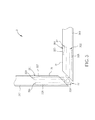
- FIG. 3 is a diagram of a corner key 32 according to an embodiment of the present invention.
- FIG. 4 is a diagram of a frame assembly 3 utilizing the corner key 32 in FIG. 3 .
- the corner key 32 includes a corner structure 320, a first arm portion 321, a second arm portion 322, a third arm portion 323, a fourth arm portion 324, a first engaging portion 325, a second engaging portion 326, a third engaging portion 327, and a fourth engaging portion 328.
- the first arm portion 321 and the second arm portion 322 extend from a side surface 3200 of the corner structure 320 respectively, and the third arm portion 323 and the fourth arm portion 324 extend from another side surface 3201 of the corner structure 320 respectively.
- the second arm portion 322 and the fourth arm portion 324 are connected to the first arm portion 321 and the third arm portion 323 respectively via the corner structure 320.
- the first arm portion 321 has a first outer side-surface 3210.
- the second arm portion 322 has a second outer side-surface 3220.
- the third arm portion 323 has a third outer side-surface 3230.
- the fourth arm portion 324 has a fourth outer side-surface 3240.
- the first outer side-surface 3210 is unparallel to the second outer side-surface 3220.
- the third outer side-surface 3230 is unparallel to the fourth outer side-surface 3240.
- the first engaging portion 325 is disposed on the first outer side-surface 3210.
- the second engaging portion 326 is disposed on the second outer side-surface 3220.
- the third engaging portion 327 is disposed on the third outer side-surface 3230.
- the fourth engaging portion 328 is disposed on the fourth outer side-surface 3240.
- the frame assembly 3 includes two first side frames 30, two second side frames 31, and four corner keys 32.
- the first side frame 30 has a first inner hole 300
- the second side frame 31 has a second inner hole 310.
- the first arm portion 321 and the second arm portion 322 of the corner key 32 are used for assembling into the first inner hole 300 of the first side frame 30, and the third arm portion 323 and the fourth arm portion 324 of the corner key 32 are used for assembling into the second inner hole 310.
- the first side frame 30 further has a first engaging slot 301
- the second side frame 31 further has a second engaging slot 311.
- the first engaging portion 325 is engaged with the first engaging slot 301
- the third engaging portion 327 is engaged with the second engaging slot 311.
- assembly of the corner key 32, the first side frame 30, and the second side frame 31 can be more firm.
- the first side frames 30 and the adjacent second side frame 31 are assembled to each other by one corner key 32.
- the structures of the third arm portion 323, the fourth arm portion 324, the third engaging portion 327, and the fourth engaging portion 328 are substantially identical to the structures of the first arm portion 321, the second arm portion 322, the first engaging portion 325, and the second engaging portion 326.
- first arm portion 321, the second arm portion 322, the first engaging portion 325, and the second engaging portion 326 are described in detail as follows for simplicity.
- the first engaging portion 325 is located at a first head end 3211 of the first arm portion 321.
- the first arm portion 321 has a first section 3212 close to the first engaging portion 325 and a second section 3213 away from the first engaging portion 325.
- a thickness T 1 of the first section 3212 is greater than a thickness T 2 of the second section 3213.
- the second engaging portion 326 is located at a second head end 3221 of the second arm portion 322.
- the second arm portion 322 has a third section 3222 close to the second engaging portion 326 and a fourth section 3223 away from the second engaging portion 326.
- a thickness T 3 of the third section 3222 is greater than a thickness T 4 of the fourth section 3223.
- the first arm portion 321 and the second arm portion 322 can be more flexible, so that excessive interference of the first engaging portion 325, the second engaging portion 326 and the first inner hole 300 of the first side frame 30 can be avoided.
- the second engaging portion 326 is a tooth structure that is inverted-tooth shaped and the first engaging portion 325 is a hook structure that is inverted-tooth shaped, but the structural designs of the second engaging portion 326 and the first engaging portion 325 are not limited thereto.
- the first engaging portion 325 can also be a tooth structure that is inverted-tooth shaped.
- an angle ⁇ 1 between a first extending line L 1 of the first outer side-surface 3210 and a second extending line L 2 of the second outer side-surface 3220 is preferably greater than 0° and less than or equal to 30°.
- FIG. 5 is a diagram of the corner key 32 in FIG. 3 being assembled into the first side frame 30.
- the first engaging portion 325 and the second engaging portion 326 are compressed by the inner wall of the first inner hole 300, so as to make the first arm portion 321 bend inwardly (as shown in FIG. 5 ).
- the first engaging portion 325 and the second engaging portion 326 may generate a self-tightening force due to elastic force provided by the first arm portion 321 and the second arm portion 322, so as to grip the first engaging slot 301 and the first inner hole 300 of the first side frame 30 tightly. Accordingly, after assembly of the first side frame 30 and the corner key 32 is completed, there is no need to additionally utilize a mounting process to make the first engaging portion 325 and the second engaging portion 326 grip the first side frame 30 tightly.
- the second side frame 31 and the corner key 32 can be substantially identical to assembly of the first side frame 30 and the corner key 32.
- the third engaging portion 327 moves inward relative to the second inner hole 310 to a position corresponding to the second engaging slot 311, the third engaging portion 327 is driven to be engaged with the second engaging slot 311 by elastic force provided from the third arm portion 323, so as to complete assembly of the second side frame 31 and the corner key 32.
- the third engaging portion 327 and the fourth engaging portion 328 may generate a self-tightening force due to elastic force provided from the third arm portion 323 and the fourth arm portion 324 so as to grip the second engaging slot 311 and the second inner hole 310 of the second side frame 31 tightly. Accordingly, after the assembly process of the second side frame 31 and the corner key 32 is completed, there is no need to additionally utilize a mounting process to make the third engaging portion 327 and the fourth engaging portion 328 grip the second side frame 31 tightly.
- FIG. 6 is a diagram of a corner key 32' according to another embodiment of the present invention.
- a major difference between the corner key 32' and the corner key 32 is the structural design of the first arm portion 321.
- the structures of the third arm portion 323 and the fourth arm portion 324 are substantially identical to the structures of the first arm portion 321 and the second arm portion 322.
- the structural designs of the first arm portion 321 and the second arm portion 322 are described in details as follows for simplicity.
- the second arm portion 322 extends from the corner structure 320
- the first arm portion 321 extends from the second arm portion 322 and bends toward the corner structure 320.
- the first arm portion 321 has the first outer side-surface 3210
- the second arm portion 322 has the second outer side-surface 3220.
- the first outer side-surface 3210 is unparallel to the second outer side-surface 3220.
- the first engaging portion 325 is located at the first head end 3211 of the first arm portion 321, and the second engaging portion 326 is located at the second head end 3221 of the second arm portion 322.
- the first arm portion 321 utilizes the second section 3213 away from the first engaging portion 325 to be connected to the second head end 3221 of the second arm portion 322 instead, so that the first arm portion 321 can extend from the second arm portion 322 and bend toward the corner structure 320 accordingly.
- the first arm portion 321 instead of the design in which an opening 330 formed by the first arm portion 321 and the second arm portion 322 in FIG.
- the corner key 32' utilizes the design in which the opening 330 is close to the corner structure 320 and the design in which the angle ⁇ 1 between the first extending line L 1 extending from the second section 3213 and the second extending line L 2 extending from the second head end 3221 is greater than 0° and less than or equal to 30° to make the first arm portion 321 and the second arm portion 322 in FIG. 6 capable of assembling into the first inner hole 300 more easily.
- assembly convenience of the corner key 32' and the first side frame 30 can be further enhanced.
- Other related descriptions can be reasoned by analogy according to the aforesaid embodiment and therefore omitted herein.
- FIG. 7 is a diagram of a corner key 32" according to another embodiment of the present invention.
- a major difference between the corner key 32" and the corner key 32 is the structural design of the first arm portion 321, the second arm portion 322, and the corner structure 320.
- the structures of the third arm portion 323 and the fourth arm portion 324 are substantially identical to the structures of the first arm portion 321 and the second arm portion 322.
- the structural designs of the first arm portion 321 and the second arm portion 322 are described in detail as follows for simplicity.
- an angle ⁇ 2 between the first extending line L 1 of the first outer side-surface 3210 of the first arm portion 321 and a normal line L 3 of the side surface 3200 of the corner structure 320 is greater than 0° and less than or equal to 15°
- an angle ⁇ 3 between the second extending line L 2 of the second outer side-surface 3220 of the second arm portion 322 and a normal line L 3 of the side surface 3200 of the corner structure 320 is greater than 0° and less than or equal to 15°.
- FIG. 8 is a diagram of a corner key 32"' according to another embodiment of the present invention.
- a major difference between the corner key 32"' and the corner key 32" is the side-surface designs of the first arm portion 321 and the second arm portion 322.
- the structures of the third arm portion 323 and the fourth arm portion 324 are substantially identical to the structures of the first arm portion 321 and the second arm portion 322.
- the first arm portion 321 further has a first inner side-surface 3214, and the first inner side-surface 3214 is parallel to the first outer side-surface 3210.
- the second arm portion 322 further has a second inner side-surface 3224, and the second inner side-surface 3224 is parallel to the second outer side-surface 3220.
- the present invention utilizes the design that the outer side-surfaces of the first and second arm portions of the corner key are unparallel to each other.
- the first engaging portion and the second engaging portion of the corner key can generate a self-tightening force due to elastic force of metal provided by the first arm portion and the second arm portion so as to grip the inner hole of the side frame tightly.
Landscapes
- Engineering & Computer Science (AREA)
- Civil Engineering (AREA)
- Structural Engineering (AREA)
- Lock And Its Accessories (AREA)
- Mirrors, Picture Frames, Photograph Stands, And Related Fastening Devices (AREA)
- Connection Of Plates (AREA)
- Casings For Electric Apparatus (AREA)
Abstract
A corner key (32) includes a first arm portion (321), a first engaging portion (325), a second arm portion (322), and a second engaging portion (326). The first arm portion (321) has a first outer side-surface (3210). The first engaging portion (325) is disposed on the first outer side-surface (3210). The second arm portion (322) is connected to the first arm portion (321) and has a second outer side-surface (3220). The second outer side-surface (3220) is unparallel to the first outer side-surface (3210). The second engaging portion (326) is disposed on the second outer side-surface (3220).
Description
- The present invention relates to a corner key having first and second arm portions, of which outer side-surfaces are unparallel to each other, and a frame assembly thereof according to the pre-characterizing clauses of claims 1 and 8.
- Please refer to
FIG. 1 andFIG. 2 .FIG. 1 is a diagram of acorner key 12 according to the prior art.FIG. 2 is a diagram of a frame assembly 1 utilizing thecorner key 12 inFIG. 1 . As shown inFIG. 1 , thecorner key 12 includes twobodies 120 which are connected to each other and form an L-shaped structure cooperatively. Atooth structure 122 is disposed on a surface of eachbody 120 respectively. As shown inFIG. 2 , the frame assembly 1 includes fourside frames 10 and fourcorner keys 12. Each twoadjacent side frames 10 are assembled with onecorner key 12 respectively. - In general, the
corner key 12 is usually manufactured by an aluminum extrusion process. The aluminum extrusion process is a manufacturing process with larger tolerances (concerning precision of an aluminum extrusion machine), and an anode treatment and a cutting process need to be performed on theside frame 10 during the aluminum extrusion process. Since theside frame 10 usually has burrs after being cut, assembly of thecorner key 12 and theside frame 10 is usually performed in a force fitting manner, and the sizes of theside frame 10 and thecorner key 12 vary with different mold abrasion occurring in the aluminum extrusion process, it may cause a difficult assembly process. Furthermore, during the assembly process of theside frame 10 and thecorner key 12, an included-angle error between the twobodies 120 of eachcorner key 12 and a displacement difference between theside frame 10 and thecorner key 12 occurring in the assembly process may cause excessive assembly force to be applied to thecorner key 12. Accordingly, not only may thetooth structure 122 of thecorner key 12 and the related tools be damaged easily, but assembly precision of theside frame 10 and thecorner key 12 may also be influenced, reducing the production capacity of the frame assembly and increasing the maintenance and replacement cost of the related process apparatuses. - This in mind, the present invention aims at providing a corner key having first and second arm portions, of which outer side-surfaces are unparallel to each other, so that the first arm portion and the second arm portion can grip an inner hole of a side frame tightly due to elastic force provided by the first arm portion and the second arm portion after the assembly process of the side frame and the corner key is completed.
- This is achieved by a corner key and a frame assembly thereof according to claims 1 and 8. The dependent claims pertain to corresponding further developments and improvements.
- As will be seen more clearly from the detailed description following below, the claimed corner key includes a first arm portion, a first engaging portion, a second arm portion, and a second engaging portion. The first arm portion has a first outer side-surface. The first engaging portion is disposed on the first outer side-surface. The second arm portion is connected to the first arm portion and has a second outer side-surface. The second outer side-surface is unparallel to the first outer side-surface. The second engaging portion is disposed on the second outer side-surface.
- The claimed frame assembly includes a first side frame and a corner key. The first side frame has a first inner hole. The corner key includes a first arm portion, a first engaging portion, a second engaging portion, and a second engaging portion. The first arm portion has a first outer side-surface. The first engaging portion is disposed on the first outer side-surface. The second arm portion is connected to the first arm portion and has a second outer side-surface. The second outer side-surface is unparallel to the first outer side-surface. The second engaging portion is disposed on the second outer side-surface. The first arm portion and the second arm portion are used for assembling into the first inner hole.
- In the following, the invention is further illustrated by way of example, taking reference to the accompanying drawings thereof:
-
FIG. 1 is a diagram of a corner key according to the prior art, -
FIG. 2 is a diagram of a frame assembly utilizing the corner key inFIG. 1 , -
FIG. 3 is a diagram of a corner key according to an embodiment of the present invention, -
FIG. 4 is a diagram of a frame assembly utilizing the corner key inFIG. 3 , -
FIG. 5 is a diagram of the corner key inFIG. 3 being assembled into a first side frame, -
FIG. 6 is a diagram of a corner key according to another embodiment of the present invention, -
FIG. 7 is a diagram of a corner key according to another embodiment of the present invention, and -
FIG. 8 is a diagram of a corner key according to another embodiment of the present invention. - Please refer to
FIG. 3 andFIG. 4 .FIG. 3 is a diagram of acorner key 32 according to an embodiment of the present invention.FIG. 4 is a diagram of aframe assembly 3 utilizing thecorner key 32 inFIG. 3 . As shown inFIG. 3 , thecorner key 32 includes acorner structure 320, afirst arm portion 321, asecond arm portion 322, athird arm portion 323, afourth arm portion 324, a firstengaging portion 325, a secondengaging portion 326, a thirdengaging portion 327, and a fourthengaging portion 328. Thefirst arm portion 321 and thesecond arm portion 322 extend from aside surface 3200 of thecorner structure 320 respectively, and thethird arm portion 323 and thefourth arm portion 324 extend from anotherside surface 3201 of thecorner structure 320 respectively. In other words, thesecond arm portion 322 and thefourth arm portion 324 are connected to thefirst arm portion 321 and thethird arm portion 323 respectively via thecorner structure 320. Thefirst arm portion 321 has a first outer side-surface 3210. Thesecond arm portion 322 has a second outer side-surface 3220. Thethird arm portion 323 has a third outer side-surface 3230. Thefourth arm portion 324 has a fourth outer side-surface 3240. The first outer side-surface 3210 is unparallel to the second outer side-surface 3220. The third outer side-surface 3230 is unparallel to the fourth outer side-surface 3240. The firstengaging portion 325 is disposed on the first outer side-surface 3210. The secondengaging portion 326 is disposed on the second outer side-surface 3220. The thirdengaging portion 327 is disposed on the third outer side-surface 3230. The fourthengaging portion 328 is disposed on the fourth outer side-surface 3240. - As shown in
FIG. 4 , theframe assembly 3 includes twofirst side frames 30, twosecond side frames 31, and fourcorner keys 32. Thefirst side frame 30 has a firstinner hole 300, and thesecond side frame 31 has a secondinner hole 310. Thefirst arm portion 321 and thesecond arm portion 322 of thecorner key 32 are used for assembling into the firstinner hole 300 of thefirst side frame 30, and thethird arm portion 323 and thefourth arm portion 324 of thecorner key 32 are used for assembling into the secondinner hole 310. In this embodiment, thefirst side frame 30 further has a firstengaging slot 301, and thesecond side frame 31 further has a secondengaging slot 311. Accordingly, when thefirst arm portion 321 is assembled into the firstinner hole 300, the first engagingportion 325 is engaged with the firstengaging slot 301, and when thethird arm portion 323 is assembled into the secondinner hole 310, the thirdengaging portion 327 is engaged with the secondengaging slot 311. In such a manner, assembly of thecorner key 32, thefirst side frame 30, and thesecond side frame 31 can be more firm. In other words, the first side frames 30 and the adjacentsecond side frame 31 are assembled to each other by onecorner key 32. - In this embodiment, the structures of the
third arm portion 323, thefourth arm portion 324, the thirdengaging portion 327, and the fourth engagingportion 328 are substantially identical to the structures of thefirst arm portion 321, thesecond arm portion 322, the first engagingportion 325, and the secondengaging portion 326. Thus, only the structural designs of thefirst arm portion 321, thesecond arm portion 322, the first engagingportion 325, and the secondengaging portion 326 are described in detail as follows for simplicity. - As shown in
FIG. 3 , the first engagingportion 325 is located at afirst head end 3211 of thefirst arm portion 321. Thefirst arm portion 321 has afirst section 3212 close to the first engagingportion 325 and asecond section 3213 away from the first engagingportion 325. A thickness T1 of thefirst section 3212 is greater than a thickness T2 of thesecond section 3213. The secondengaging portion 326 is located at asecond head end 3221 of thesecond arm portion 322. Thesecond arm portion 322 has athird section 3222 close to the secondengaging portion 326 and afourth section 3223 away from the secondengaging portion 326. A thickness T3 of thethird section 3222 is greater than a thickness T4 of thefourth section 3223. Accordingly, thefirst arm portion 321 and thesecond arm portion 322 can be more flexible, so that excessive interference of the first engagingportion 325, the secondengaging portion 326 and the firstinner hole 300 of thefirst side frame 30 can be avoided. In this embodiment, the secondengaging portion 326 is a tooth structure that is inverted-tooth shaped and the first engagingportion 325 is a hook structure that is inverted-tooth shaped, but the structural designs of the secondengaging portion 326 and the first engagingportion 325 are not limited thereto. For example, the first engagingportion 325 can also be a tooth structure that is inverted-tooth shaped. Furthermore, an angle θ1 between a first extending line L1 of the first outer side-surface 3210 and a second extending line L2 of the second outer side-surface 3220 is preferably greater than 0° and less than or equal to 30°. - More detailed description for assembly of the
first side frame 30 and thecorner key 32 is provided as follows. Please refer toFIG. 4 andFIG. 5. FIG. 5 is a diagram of thecorner key 32 inFIG. 3 being assembled into thefirst side frame 30. As shown inFIG. 4 andFIG. 5 , during the assembly process of assembling thefirst arm portion 321 and thesecond arm portion 322 of thecorner key 32 into the firstinner hole 300 of thefirst side frame 30, the first engagingportion 325 and the secondengaging portion 326 are compressed by the inner wall of the firstinner hole 300, so as to make thefirst arm portion 321 bend inwardly (as shown inFIG. 5 ). Accordingly, poor assembly quality of theframe assembly 3 or damage of the first engagingportion 325 caused by excessive interference of the first engagingportion 325 and the firstinner hole 300 of thefirst side frame 30 can be avoided. Subsequently, when the first engagingportion 325 moves inward relative to the firstinner hole 300 to a position corresponding to the firstengaging slot 301, the first engagingportion 325 is driven to be engaged with the firstengaging slot 301 by elastic force provided by thefirst arm portion 321, so as to complete assembly of thefirst side frame 30 and thecorner key 32. - After assembly of the
first side frame 30 and thecorner key 32 is completed, the first engagingportion 325 and the secondengaging portion 326 may generate a self-tightening force due to elastic force provided by thefirst arm portion 321 and thesecond arm portion 322, so as to grip the firstengaging slot 301 and the firstinner hole 300 of thefirst side frame 30 tightly. Accordingly, after assembly of thefirst side frame 30 and thecorner key 32 is completed, there is no need to additionally utilize a mounting process to make the first engagingportion 325 and the secondengaging portion 326 grip thefirst side frame 30 tightly. - As for assembly of the
second side frame 31 and thecorner key 32, it can be substantially identical to assembly of thefirst side frame 30 and thecorner key 32. In brief, when the thirdengaging portion 327 moves inward relative to the secondinner hole 310 to a position corresponding to the secondengaging slot 311, the thirdengaging portion 327 is driven to be engaged with the secondengaging slot 311 by elastic force provided from thethird arm portion 323, so as to complete assembly of thesecond side frame 31 and thecorner key 32. - Similarly, after assembly of the
second side frame 31 and thecorner key 32 is completed, the thirdengaging portion 327 and the fourth engagingportion 328 may generate a self-tightening force due to elastic force provided from thethird arm portion 323 and thefourth arm portion 324 so as to grip the secondengaging slot 311 and the secondinner hole 310 of thesecond side frame 31 tightly. Accordingly, after the assembly process of thesecond side frame 31 and thecorner key 32 is completed, there is no need to additionally utilize a mounting process to make the thirdengaging portion 327 and the fourth engagingportion 328 grip thesecond side frame 31 tightly. - Please refer
FIG. 6 , which is a diagram of a corner key 32' according to another embodiment of the present invention. A major difference between the corner key 32' and thecorner key 32 is the structural design of thefirst arm portion 321. In this embodiment, the structures of thethird arm portion 323 and thefourth arm portion 324 are substantially identical to the structures of thefirst arm portion 321 and thesecond arm portion 322. Thus, only the structural designs of thefirst arm portion 321 and thesecond arm portion 322 are described in details as follows for simplicity. In this embodiment, thesecond arm portion 322 extends from thecorner structure 320, and thefirst arm portion 321 extends from thesecond arm portion 322 and bends toward thecorner structure 320. Thefirst arm portion 321 has the first outer side-surface 3210, and thesecond arm portion 322 has the second outer side-surface 3220. The first outer side-surface 3210 is unparallel to the second outer side-surface 3220. The firstengaging portion 325 is located at thefirst head end 3211 of thefirst arm portion 321, and the secondengaging portion 326 is located at thesecond head end 3221 of thesecond arm portion 322. - To be more specific, in this embodiment, the
first arm portion 321 utilizes thesecond section 3213 away from the first engagingportion 325 to be connected to thesecond head end 3221 of thesecond arm portion 322 instead, so that thefirst arm portion 321 can extend from thesecond arm portion 322 and bend toward thecorner structure 320 accordingly. In such a manner, instead of the design in which anopening 330 formed by thefirst arm portion 321 and thesecond arm portion 322 inFIG. 3 is away from thecorner structure 320, the corner key 32' utilizes the design in which theopening 330 is close to thecorner structure 320 and the design in which the angle θ1 between the first extending line L1 extending from thesecond section 3213 and the second extending line L2 extending from thesecond head end 3221 is greater than 0° and less than or equal to 30° to make thefirst arm portion 321 and thesecond arm portion 322 inFIG. 6 capable of assembling into the firstinner hole 300 more easily. Thus, assembly convenience of the corner key 32' and thefirst side frame 30 can be further enhanced. Other related descriptions can be reasoned by analogy according to the aforesaid embodiment and therefore omitted herein. - Please refer to
FIG. 7 , which is a diagram of acorner key 32" according to another embodiment of the present invention. A major difference between thecorner key 32" and thecorner key 32 is the structural design of thefirst arm portion 321, thesecond arm portion 322, and thecorner structure 320. In this embodiment, the structures of thethird arm portion 323 and thefourth arm portion 324 are substantially identical to the structures of thefirst arm portion 321 and thesecond arm portion 322. Thus, only the structural designs of thefirst arm portion 321 and thesecond arm portion 322 are described in detail as follows for simplicity. - In this embodiment, an angle θ2 between the first extending line L1 of the first outer side-
surface 3210 of thefirst arm portion 321 and a normal line L3 of theside surface 3200 of thecorner structure 320 is greater than 0° and less than or equal to 15°, and an angle θ3 between the second extending line L2 of the second outer side-surface 3220 of thesecond arm portion 322 and a normal line L3 of theside surface 3200 of thecorner structure 320 is greater than 0° and less than or equal to 15°. Other related designs in this embodiment can be reasoned by analogy according to the aforesaid embodiments and are therefore omitted herein. - Please refer to
FIG. 8 , which is a diagram of acorner key 32"' according to another embodiment of the present invention. A major difference between thecorner key 32"' and thecorner key 32" is the side-surface designs of thefirst arm portion 321 and thesecond arm portion 322. In this embodiment, the structures of thethird arm portion 323 and thefourth arm portion 324 are substantially identical to the structures of thefirst arm portion 321 and thesecond arm portion 322. Thus, only the structural designs of thefirst arm portion 321 and thesecond arm portion 322 are described in detail as follows for simplicity. In this embodiment, thefirst arm portion 321 further has a first inner side-surface 3214, and the first inner side-surface 3214 is parallel to the first outer side-surface 3210. Thesecond arm portion 322 further has a second inner side-surface 3224, and the second inner side-surface 3224 is parallel to the second outer side-surface 3220. As for other related designs in this embodiment, it can be reasoned by analogy according to the aforesaid embodiments and therefore omitted herein. - Compared with the prior art, the present invention utilizes the design that the outer side-surfaces of the first and second arm portions of the corner key are unparallel to each other. After the assembly process of the side frame and the corner key is completed, the first engaging portion and the second engaging portion of the corner key can generate a self-tightening force due to elastic force of metal provided by the first arm portion and the second arm portion so as to grip the inner hole of the side frame tightly. In such a manner, after the assembly process of the side frame and the corner key is completed, there is no need to additionally utilize a mounting process to make the interference between the corner key and the side frame.
Claims (15)
- A corner key (32) characterized by: the corner key (32) comprising:a first arm portion (321) having a first outer side-surface (3210);a first engaging portion (325) disposed on the first outer side-surface (3210);a second arm portion (322) connected to the first arm portion (321) and
having a second outer side-surface (3220), the second outer side-surface (3220) being unparallel to the first outer side-surface (3210); anda second engaging portion (326) disposed on the second outer side-surface (3220). - The corner key (32) of claim 1 characterized in that an angle between a first extending line of the first outer side-surface (3210) and a second extending line of the second outer side-surface (3220) is greater than 0° and less than or equal to 30°.
- The corner key (32) of claim 1 characterized in that the first engaging portion (325) is located at a first head end (3211) of the first arm portion (321), the first arm portion (321) has a first section (3212) close to the first engaging portion (325) and a second section (3213) away from the first engaging portion (325), a thickness of the first section (3212) is greater than a thickness of the second section (3213), the second engaging portion (326) is located at a second head end (3221) of the second arm portion (322), the second arm portion (322) has a third section (3222) close to the second engaging portion (326) and a fourth section (3223) away from the second engaging portion (326), and a thickness of the third section (3222) is greater than a thickness of the fourth section (3223).
- The corner key of claim 1 characterized in that the corner key further comprises:a corner structure (320), the first arm portion (321) and the second arm
portion (322) extending from the corner structure (320) respectively, an angle between a first extending line of the first outer side-surface (3210) and a normal line of a side surface (3200) of the corner structure (320) being greater than 0° and less than or equal to 15°, and an angle between a second extending line of the second outer side-surface (3220) and the normal line being greater than 0° and less than or equal to 15°. - The corner key of claim 1 characterized in that the corner key further comprises:a corner structure (320), the second arm portion (322) extending from the
corner structure (320), and the first arm portion (321) extending from the second arm portion (322) and bending toward the corner structure (320), an angle between a first extending line of the first outer side-surface (3210) and a normal line of a side surface (3200) of the corner structure (320) being greater than 0° and less than or equal to 15°, and an angle between a second extending line of the second outer side-surface (3220) and the normal line being greater than 0° and less than or equal to 15°. - The corner key of claim 1 characterized in that the first arm portion (321) further has a first inner side-surface (3214), the first inner side-surface (3214) is parallel to the first outer side-surface (3210), the second arm portion (322) further has a second inner side-surface (3224), and the second inner side-surface (3224) is parallel to the second outer side-surface (3220).
- The corner key (32) of claim 1 characterized in that the corner key (32) further comprises:a third arm portion (323) having a third outer side-surface (3230);a third engaging portion (327) disposed on the third outer side-surface (3230);a fourth arm portion (324) connected to the third arm portion (323) and having
a fourth outer side-surface (3240), the fourth outer side-surface (3240) being unparallel to the third outer side-surface (3230); anda fourth engaging portion (328) disposed on the fourth outer side-surface (3240). - A frame assembly (3) comprising:a first side frame (30) having a first inner hole (300); andcharacterized by: a corner key (32) comprising:a first arm portion (321) having a first outer side-surface (3210);a first engaging portion (325) disposed on the first outer side-surface (3210);a second arm portion (322) connected to the first arm portion (321) and
having a second outer side-surface (3220), the second outer side-surface (3220) being unparallel to the first outer side-surface (3210); anda second engaging portion (326) disposed on the second outerwherein the first arm portion (321) and the second arm portion (322) are used for assembling into the first inner hole (300).
side-surface (3220); - The frame assembly (3) of claim 8 characterized in that an angle between a first extending line of the first outer side-surface (3210) and a second extending line of the second outer side-surface (3220) is greater than 0° and less than or equal to 30°.
- The frame assembly (3) of claim 8 characterized in that the first engaging portion (325) is located at a first head end (3211) of the first arm portion (321), the first arm portion (321) has a first section (3212) close to the first engaging portion (325) and a second section (3213) away from the first engaging portion (325), a thickness of the first section (3212) is greater than a thickness of the second section (3213), the second engaging portion (326) is located at a second head end (3221) of the second arm portion (322), the second arm portion (322) has a third section (3222) close to the second engaging portion (326) and a fourth section (3223) away from the second engaging portion (326), and a thickness of the third section (3222) is greater than a thickness of the fourth section (3223).
- The frame assembly (3) of claim 8 characterized in that the corner key further comprises a corner structure (320), the first arm portion (321) and the second arm portion (322) extend from the corner structure (320) respectively, an angle between a first extending line of the first outer side-surface (3210) and a normal line of a side surface (3200) of the corner structure (320) is greater than 0° and less than or equal to 15°, and an angle between a second extending line of the second outer side-surface (3220) and the normal line is greater than 0° and less than or equal to 15°.
- The frame assembly (3) of claim 8 characterized in that the corner key further comprises a corner structure (320), the second arm portion (322) extends from the corner structure (320), the first arm portion (321) extends from the second arm portion (322) and bends toward the corner structure (320), an angle between a first extending line of the first outer side-surface (3210) and a normal line of a side surface (3200) of the corner structure (320) is greater than 0° and less than or equal to 15°, and an angle between a second extending line of the second outer side-surface (3220) and the normal line is greater than 0° and less than or equal to 15°.
- The frame assembly (3) of claim 8 characterized in that the first arm portion (321) further has a first inner side-surface (3214), the first inner side-surface (3214) is parallel to the first outer side-surface (3210), the second arm portion (322) further has a second inner side-surface (3224), and the second inner side-surface (3224) is parallel to the second outer side-surface (3220).
- The frame assembly (3) of claim 8 characterized in that the first side frame (30) has a first engaging slot (301), and the first engaging portion (325) is engaged with the first engaging slot (301) when the first arm portion (321) is assembled into the first inner hole (300).
- The frame assembly (3) of claim 8 characterized in that the frame assembly (3) further comprises:a second side frame (31) having a second inner hole (310) and a secondwherein the third arm portion (323) and the fourth arm portion (324) are used for assembling into the second inner hole (310), and the third engaging portion (327) is engaged with the second engaging slot (311) when the third arm portion (323) is assembled into the second inner hole (310).
engaging slot (311), the corner key (32) further comprising:a third arm portion (323) having a third outer side-surface (3230);a third engaging portion (327) disposed on the third outer side-surface (3230);a fourth arm portion (324) connected to the third arm portion (323) and
having a fourth outer side-surface (3240), the fourth outer side-surface (3240) being unparallel to the third outer side-surface (3230); anda fourth engaging portion (328) disposed on the fourth outer side-surface (3240);
Applications Claiming Priority (1)
| Application Number | Priority Date | Filing Date | Title |
|---|---|---|---|
| TW100132495A TWI507612B (en) | 2011-09-08 | 2011-09-08 | Corner key and frame assembly thereof |
Publications (1)
| Publication Number | Publication Date |
|---|---|
| EP2568104A1 true EP2568104A1 (en) | 2013-03-13 |
Family
ID=45912239
Family Applications (1)
| Application Number | Title | Priority Date | Filing Date |
|---|---|---|---|
| EP12161442A Withdrawn EP2568104A1 (en) | 2011-09-08 | 2012-03-27 | Corner key and frame assembly thereof |
Country Status (4)
| Country | Link |
|---|---|
| US (1) | US20130064600A1 (en) |
| EP (1) | EP2568104A1 (en) |
| CN (1) | CN102409936A (en) |
| TW (1) | TWI507612B (en) |
Cited By (8)
| Publication number | Priority date | Publication date | Assignee | Title |
|---|---|---|---|---|
| EP2682555A3 (en) * | 2012-07-06 | 2014-08-13 | REHAU AG + Co | Corner connection element |
| CN104333301A (en) * | 2014-11-14 | 2015-02-04 | 苏州东润太阳能科技有限公司 | Corner key for assembling solar battery frame |
| GB2546477A (en) * | 2016-01-12 | 2017-07-26 | Imagewall Ltd | Exhibition system |
| CN111364901A (en) * | 2020-04-08 | 2020-07-03 | 汤军 | A window grille and window |
| US11744390B2 (en) | 2010-05-14 | 2023-09-05 | Mcs Industries, Inc. | Hanging apparatus |
| USD1054595S1 (en) | 2022-01-26 | 2024-12-17 | Mcs Industries, Inc. | Connector for molding |
| USD1057216S1 (en) | 2022-01-26 | 2025-01-07 | Mcs Industries, Inc. | Molding |
| US12305407B2 (en) | 2022-01-26 | 2025-05-20 | Mcs Industries, Inc. | Decorative moulding assembly and method of manufacturing and assembling the same |
Families Citing this family (15)
| Publication number | Priority date | Publication date | Assignee | Title |
|---|---|---|---|---|
| KR101387318B1 (en) * | 2013-11-05 | 2014-04-18 | 김순석 | Multipurpose windows and doors device prefabricatd structure that have deformed frame structure |
| AT515184B1 (en) * | 2013-12-13 | 2015-12-15 | Walter Ing Degelsegger | Device for closing a building opening |
| WO2016007794A1 (en) * | 2014-07-09 | 2016-01-14 | Clear Wall Corporation | Systems and methods related to energy-efficient fenestration assemblies |
| CN104320059A (en) * | 2014-11-18 | 2015-01-28 | 苏州东润太阳能科技有限公司 | Novel angle key for fixing frame capable of being transversely cascaded |
| US9366072B1 (en) * | 2015-02-23 | 2016-06-14 | Jose Humberto Orozco Aguayo | Adjustable screen frame assembly |
| CN105607324A (en) * | 2016-01-05 | 2016-05-25 | 京东方科技集团股份有限公司 | Front frame, display module and display device |
| US10472823B2 (en) * | 2016-06-24 | 2019-11-12 | Apache Industrial Services, Inc. | Formwork system |
| US11078720B2 (en) | 2019-05-09 | 2021-08-03 | Amesbury Group, Inc. | Corner key for extruded windows and doors |
| USD909855S1 (en) * | 2019-05-09 | 2021-02-09 | Amesbury Group, Inc. | Corner key |
| CN110847390A (en) * | 2019-11-28 | 2020-02-28 | 湖南麓上住宅工业科技有限公司 | Wood structure wallboard connecting piece |
| TWI734391B (en) | 2020-02-27 | 2021-07-21 | 友達光電股份有限公司 | Back light module |
| US12025176B2 (en) | 2021-03-17 | 2024-07-02 | Steelcase Inc. | Clip fastener for privacy screen |
| US20230237939A1 (en) * | 2022-01-24 | 2023-07-27 | Budnick Converting, Inc. | Frame assembly for displaying a tensionable media |
| PL4339412T3 (en) * | 2022-09-13 | 2025-07-14 | L.M. Dei F.Lli Monticelli S.R.L. | Elastic corner joint for the connection of profiles |
| US20250172036A1 (en) * | 2023-11-28 | 2025-05-29 | Mi Windows And Doors, Llc | Frame corner key |
Citations (7)
| Publication number | Priority date | Publication date | Assignee | Title |
|---|---|---|---|---|
| US3546842A (en) * | 1969-05-27 | 1970-12-15 | Koller Craft Plastic Products | Panel assembly |
| AU411736B2 (en) * | 1967-06-20 | 1971-03-25 | L shaped stakes for forming angular joints between hollow sectioned elongate members | |
| US3579724A (en) * | 1967-05-08 | 1971-05-25 | Anchor Enterprises Corp | Apparatus for the manufacture of composite structural elements |
| FR2240373A1 (en) * | 1973-08-10 | 1975-03-07 | Vangheluwe Jozef | Door or window frame member angle joint - has L-shaped piece with spring lips engaging in recesses in member walls |
| DE2456285A1 (en) * | 1974-11-28 | 1976-08-12 | Kreusel | Coupling element for hollow profile tubes - has rocking lever to produce wedge like friction connection on tube internal walls |
| US4077160A (en) * | 1976-12-16 | 1978-03-07 | Empire Metal Products Corporation | Screen door construction |
| WO1984002559A1 (en) * | 1982-12-29 | 1984-07-05 | Japan Art Kikaku Co Ltd | Coupling device for formed frame |
Family Cites Families (22)
| Publication number | Priority date | Publication date | Assignee | Title |
|---|---|---|---|---|
| US2188209A (en) * | 1938-07-28 | 1940-01-23 | Charles M Clarke | Means for connecting frame members |
| US2894579A (en) * | 1954-07-22 | 1959-07-14 | Rylock Company Ltd | Screen door with metallic frame |
| US2996159A (en) * | 1958-06-02 | 1961-08-15 | Ralph T Casebolt | Miter joint |
| US3485519A (en) * | 1967-07-24 | 1969-12-23 | Joseph Chak Fai Chiu | Readily demountable constructional unit |
| GB1148411A (en) * | 1968-12-30 | 1969-04-10 | Joseph Chak Fai Chiu | A tube connecting member |
| US3627359A (en) * | 1970-01-06 | 1971-12-14 | Nat Screen Service Corp | Frame corner lock |
| US3698114A (en) * | 1971-03-15 | 1972-10-17 | Structural Ind Inc | Frame construction |
| US3765541A (en) * | 1971-04-07 | 1973-10-16 | Poster Products | Structural units and method of assembling them |
| US3899844A (en) * | 1973-09-21 | 1975-08-19 | Ben Munn | Joint member and rail with clips for picture framing |
| GB2020390A (en) * | 1978-03-15 | 1979-11-14 | Heywood W Ltd | Corner connector for frames |
| US4205470A (en) * | 1978-03-16 | 1980-06-03 | Kapnek Bertram H | Frame |
| US4452138A (en) * | 1982-06-17 | 1984-06-05 | American Screen Printing Equipment Co. | Screen printing frame |
| US4701066A (en) * | 1986-05-20 | 1987-10-20 | Wright Line, Incorporated | Decorative sound absorbing panel for furniture |
| US4838332A (en) * | 1986-10-28 | 1989-06-13 | Mlenek Patrick L | Swinging screen door for sliding glass doors |
| US4962805A (en) * | 1987-12-11 | 1990-10-16 | Lunstead, Inc. | Furniture connector |
| US5564758A (en) * | 1995-01-17 | 1996-10-15 | Century Manufacturing Co., Inc. | Angled plates for connecting ducts |
| DE19536037C1 (en) * | 1995-09-28 | 1996-11-28 | Ekonal Bausysteme Gmbh & Co Kg | Corner connector for mitred picture frame profiles etc. |
| DE19707951A1 (en) * | 1997-02-27 | 1998-09-03 | Goetz Guddas | Furniture door and connection means for a furniture door |
| BE1012394A3 (en) * | 1998-09-29 | 2000-10-03 | Brochez Alain | Corner connection and method for manufacturing of such area connection and plug-in brackets to such area link to realize. |
| JP2000262371A (en) * | 1999-03-15 | 2000-09-26 | Epoch Sha:Kk | Frame corner connecting device |
| JP2003278457A (en) * | 2002-01-15 | 2003-10-02 | Nippon Kentetsu Co Ltd | Coupling structure for sash frame member |
| CN201896554U (en) * | 2010-10-28 | 2011-07-13 | 广东伟业铝厂有限公司 | Aluminum alloy door and window corner connector |
-
2011
- 2011-09-08 TW TW100132495A patent/TWI507612B/en not_active IP Right Cessation
- 2011-11-07 CN CN2011103530716A patent/CN102409936A/en active Pending
-
2012
- 2012-03-27 EP EP12161442A patent/EP2568104A1/en not_active Withdrawn
- 2012-05-23 US US13/478,134 patent/US20130064600A1/en not_active Abandoned
Patent Citations (7)
| Publication number | Priority date | Publication date | Assignee | Title |
|---|---|---|---|---|
| US3579724A (en) * | 1967-05-08 | 1971-05-25 | Anchor Enterprises Corp | Apparatus for the manufacture of composite structural elements |
| AU411736B2 (en) * | 1967-06-20 | 1971-03-25 | L shaped stakes for forming angular joints between hollow sectioned elongate members | |
| US3546842A (en) * | 1969-05-27 | 1970-12-15 | Koller Craft Plastic Products | Panel assembly |
| FR2240373A1 (en) * | 1973-08-10 | 1975-03-07 | Vangheluwe Jozef | Door or window frame member angle joint - has L-shaped piece with spring lips engaging in recesses in member walls |
| DE2456285A1 (en) * | 1974-11-28 | 1976-08-12 | Kreusel | Coupling element for hollow profile tubes - has rocking lever to produce wedge like friction connection on tube internal walls |
| US4077160A (en) * | 1976-12-16 | 1978-03-07 | Empire Metal Products Corporation | Screen door construction |
| WO1984002559A1 (en) * | 1982-12-29 | 1984-07-05 | Japan Art Kikaku Co Ltd | Coupling device for formed frame |
Cited By (13)
| Publication number | Priority date | Publication date | Assignee | Title |
|---|---|---|---|---|
| US12408772B2 (en) | 2010-05-14 | 2025-09-09 | Mcs Industries, Inc. | Hanging apparatus |
| US11744390B2 (en) | 2010-05-14 | 2023-09-05 | Mcs Industries, Inc. | Hanging apparatus |
| US11771245B1 (en) | 2010-05-14 | 2023-10-03 | Mcs Industries, Inc. | Hanging apparatus |
| EP2682555A3 (en) * | 2012-07-06 | 2014-08-13 | REHAU AG + Co | Corner connection element |
| CN104333301A (en) * | 2014-11-14 | 2015-02-04 | 苏州东润太阳能科技有限公司 | Corner key for assembling solar battery frame |
| GB2546477A (en) * | 2016-01-12 | 2017-07-26 | Imagewall Ltd | Exhibition system |
| CN111364901A (en) * | 2020-04-08 | 2020-07-03 | 汤军 | A window grille and window |
| USD1054595S1 (en) | 2022-01-26 | 2024-12-17 | Mcs Industries, Inc. | Connector for molding |
| US12305407B2 (en) | 2022-01-26 | 2025-05-20 | Mcs Industries, Inc. | Decorative moulding assembly and method of manufacturing and assembling the same |
| USD1087400S1 (en) | 2022-01-26 | 2025-08-05 | Mcs Industries, Inc. | Molding |
| USD1057216S1 (en) | 2022-01-26 | 2025-01-07 | Mcs Industries, Inc. | Molding |
| USD1098501S1 (en) | 2022-01-26 | 2025-10-14 | Mcs Industries, Inc. | Molding |
| USD1098500S1 (en) | 2022-01-26 | 2025-10-14 | Mcs Industries, Inc. | Connector for molding |
Also Published As
| Publication number | Publication date |
|---|---|
| TWI507612B (en) | 2015-11-11 |
| TW201312015A (en) | 2013-03-16 |
| CN102409936A (en) | 2012-04-11 |
| US20130064600A1 (en) | 2013-03-14 |
Similar Documents
| Publication | Publication Date | Title |
|---|---|---|
| US20130064600A1 (en) | Corner key and frame assembly thereof | |
| EP2549050A1 (en) | Corner key and frame assembly | |
| ES2821124T3 (en) | Semi-finished product of the movement regulator member, stabilizer having a movement regulating member and method of attaching the semi-finished product of the movement regulating member to the stabilizer bar | |
| EP2234173A2 (en) | Combined frame for a photovoltaic module | |
| CN109483121B (en) | Welding jig and welding frock | |
| CN103259380B (en) | A kind of processing method of electric machine casing | |
| JP6066074B2 (en) | Electric tool and battery pack used therefor | |
| US8970086B2 (en) | Stator core of rotor | |
| JP2017109275A (en) | Telescopic covers for machine tools | |
| CN103769614B (en) | telescopic shaft assembly | |
| CN104658802A (en) | Rotary knob | |
| JP6540877B2 (en) | Electric tool | |
| CN110495077A (en) | Housing, rotating electrical machine using same, and manufacturing method of housing of rotating electrical machine | |
| WO2011103116A3 (en) | Connection element for forming an interface between two parts of a machine tool that can be releasably connected to each other, and method for manufacturing such a connection element | |
| US20160010633A1 (en) | Housing and method of manufacturing the same | |
| CN202995528U (en) | Easily assembled press button | |
| JP4839423B2 (en) | Motor shaft adjusting jig and motor shaft adjusting method | |
| CN216490145U (en) | Cast aluminum rotor oblique pole tool of new energy automobile | |
| KR20090041968A (en) | Endpiece assembly of door outside belt molding | |
| CN203883588U (en) | Novel motor apparatus | |
| US20150330428A1 (en) | Catch portion, apparatus and manufacturing method of catch portion | |
| CN205653579U (en) | Sewing machine motor and sewing machine | |
| JP5531947B2 (en) | Mold | |
| JP2009291910A (en) | Structure for fixing two members, and tool holder of machine tool | |
| CN104192488B (en) | A kind of rubber chain |
Legal Events
| Date | Code | Title | Description |
|---|---|---|---|
| PUAI | Public reference made under article 153(3) epc to a published international application that has entered the european phase |
Free format text: ORIGINAL CODE: 0009012 |
|
| 17P | Request for examination filed |
Effective date: 20120327 |
|
| AK | Designated contracting states |
Kind code of ref document: A1 Designated state(s): AL AT BE BG CH CY CZ DE DK EE ES FI FR GB GR HR HU IE IS IT LI LT LU LV MC MK MT NL NO PL PT RO RS SE SI SK SM TR |
|
| AX | Request for extension of the european patent |
Extension state: BA ME |
|
| STAA | Information on the status of an ep patent application or granted ep patent |
Free format text: STATUS: EXAMINATION IS IN PROGRESS |
|
| STAA | Information on the status of an ep patent application or granted ep patent |
Free format text: STATUS: THE APPLICATION IS DEEMED TO BE WITHDRAWN |
|
| 18D | Application deemed to be withdrawn |
Effective date: 20161012 |