EP2568075A1 - Drying or washing/drying machine comprising means for treating laundry items by using vaporized condensed water - Google Patents
Drying or washing/drying machine comprising means for treating laundry items by using vaporized condensed water Download PDFInfo
- Publication number
- EP2568075A1 EP2568075A1 EP12183411A EP12183411A EP2568075A1 EP 2568075 A1 EP2568075 A1 EP 2568075A1 EP 12183411 A EP12183411 A EP 12183411A EP 12183411 A EP12183411 A EP 12183411A EP 2568075 A1 EP2568075 A1 EP 2568075A1
- Authority
- EP
- European Patent Office
- Prior art keywords
- machine
- condensed water
- drying
- steam treatment
- laundry items
- Prior art date
- Legal status (The legal status is an assumption and is not a legal conclusion. Google has not performed a legal analysis and makes no representation as to the accuracy of the status listed.)
- Withdrawn
Links
Images



Classifications
-
- D—TEXTILES; PAPER
- D06—TREATMENT OF TEXTILES OR THE LIKE; LAUNDERING; FLEXIBLE MATERIALS NOT OTHERWISE PROVIDED FOR
- D06F—LAUNDERING, DRYING, IRONING, PRESSING OR FOLDING TEXTILE ARTICLES
- D06F58/00—Domestic laundry dryers
- D06F58/20—General details of domestic laundry dryers
- D06F58/203—Laundry conditioning arrangements
-
- D—TEXTILES; PAPER
- D06—TREATMENT OF TEXTILES OR THE LIKE; LAUNDERING; FLEXIBLE MATERIALS NOT OTHERWISE PROVIDED FOR
- D06F—LAUNDERING, DRYING, IRONING, PRESSING OR FOLDING TEXTILE ARTICLES
- D06F25/00—Washing machines with receptacles, e.g. perforated, having a rotary movement, e.g. oscillatory movement, the receptacle serving both for washing and for centrifugally separating water from the laundry and having further drying means, e.g. using hot air
-
- D—TEXTILES; PAPER
- D06—TREATMENT OF TEXTILES OR THE LIKE; LAUNDERING; FLEXIBLE MATERIALS NOT OTHERWISE PROVIDED FOR
- D06F—LAUNDERING, DRYING, IRONING, PRESSING OR FOLDING TEXTILE ARTICLES
- D06F39/00—Details of washing machines not specific to a single type of machines covered by groups D06F9/00 - D06F27/00
- D06F39/40—Steam generating arrangements
-
- D—TEXTILES; PAPER
- D06—TREATMENT OF TEXTILES OR THE LIKE; LAUNDERING; FLEXIBLE MATERIALS NOT OTHERWISE PROVIDED FOR
- D06F—LAUNDERING, DRYING, IRONING, PRESSING OR FOLDING TEXTILE ARTICLES
- D06F58/00—Domestic laundry dryers
- D06F58/30—Drying processes
Definitions
- the present invention relates to a drying or washing/drying machine comprising means for subjecting laundry items to a steam treatment.
- a steam treatment allows disinfecting laundry items by reducing the bacterial charge thereof.
- such a treatment allows stretching the fabrics, which would otherwise turn out wrinkled at the end of the process.
- a well-known problem of a steam generator like the one described in the above-mentioned patent application is the formation of calcareous deposits in the coil duct 330 when non-demineralized water is vaporized therein.
- the present invention aims at solving these and other problems by providing a drying or washing/drying machine comprising means for steam treatment of laundry items.
- the present invention aims at solving these and other problems by providing a method for drying laundry items which comprises at least one steam treatment step wherein vaporized condensed water is used.
- the idea at the basis of the present invention is to generate steam by using condensed water coming from the laundry drying process, so as to prevent the drying or washing/ drying machine from having to use water from the mains.
- the water coming from the mains normally contains a more or less large quantity of limestone, which will deposit onto the walls of the coil duct during the water vaporization process, thus impairing and/or preventing the operation of said coil duct.
- a drying or washing/drying machine 1 that comprises drying means, steam treatment means for treating laundry items 2, and a tub (not shown in the figures), inside of which a rotary drum 3 is positioned, into which drum laundry items 2 can be placed for subjecting them to a drying process; said tub comprises an front access door 4, through which laundry items 2 can be loaded into or unloaded from the drum 3, an inlet 5 for a drying flow of dry hot air 51, an inlet for steam 6, arranged at the rear of the tub, and an outlet 7 for a flow of humid hot air 71.
- the drying means comprise a heater 8, preferably arranged near the back of the tub, which comprises heating means, preferably of the electric type, capable of both increasing the temperature of a dry cold air flow 52 and vaporizing a water flow; said heater 8 further comprises a cold air inlet 81, a hot air outlet 82, a water inlet 83 and a steam outlet 84.
- the heater 8 receives the dry cold air flow 52, which, by lapping heating means, preferably consisting of electric resistors, produces the drying flow of dry hot air 51, which in turn flows out through the hot air outlet 82; said hot air duct 82 is put in fluidic communication with the tub of the drying or washing/ drying machine by means of the inlet 5.
- the cold air inlet 81 may be put in fluidic communication with the outside environment or, more preferably, with condensing means. In this latter case, also the outlet 7 will have to be put in fluidic communication with said condensing means, as opposed to the outside environment, thus advantageously preventing the moisture from being dispersed in the surrounding environment. This aspect is important when the machine is to be installed in a house, in that this avoids adversely affecting the comfort of the surrounding environment.
- the condensing means comprise a thermal exchanger 9, preferably of the cross-flow type, and a tank 10 for collecting condensed water generated by condensation of moisture present in the flow of humid hot air 71.
- the thermal exchanger 9 comprises a humid hot air inlet 91 for the air flow 71, a dry cold air outlet 92 for the air flow 52, a cold cooling air inlet 93 for a cooling air flow 96, a condensate drain 94, through which a condensed water flow 98 is collected, and a hot air outlet 95 for a heated air flow 97.
- the humid hot air inlet 91 is in fluidic communication with the tub outlet 7 through an extraction duct (not shown in the figures), whereas the dry cold air outlet 92 is in fluidic communication with the tub inlet 5 through an intake duct (not shown in the figures).
- a fan 12 is installed, which speeds up the circulation of the air flows in the extraction and intake ducts.
- an anti-lint filter 11 for trapping any lint produced by the laundry items 2 during the drying treatment.
- the cold cooling air inlet 93 and the hot air outlet 95 are both in fluidic communication with the outside environment and, for the purpose of advantageously increasing the efficiency of the thermal exchanger 9, the velocity of the cooling air flow 96 may advantageously be increased by using an external fan 13.
- the condensate drain 94 is in fluidic communication with the tank 10 through a condensate duct (not shown in the figures), by means of which the condensed water flow 98 arrives at and is collected in the tank 10.
- the tank 10 comprises an outlet 101 in fluidic communication with the steam treatment means; said tank 10 is advantageously positioned near the thermal exchanger 9, preferably under it, so as to make the condensate easier to collect by gravity.
- the steam treatment means comprise the heater 8 and a pump 14, the latter comprising an intake duct and a delivery duct.
- the outlet 101 of the tank 10 is put in fluidic communication with the intake duct of the pump 14 by means of a condensed water duct (not shown in the figures), and the delivery duct 14 is in fluidic communication with the water inlet 83 of the heater 8.
- said tank 10 By using condensed water by means of the tank 10, said tank 10 needs not be filled before every drying cycle, and therefore it can advantageously be placed in the rear part of the drying or washing/drying machine, near the heater 8. In this configuration, due to the dispersed heat irradiated by the heater 8, the temperature of the water contained in the tank 10 is advantageously higher than ambient temperature.
- the action of the heater 8 vaporizes the water flow, thus transforming it into a steam flow, which exits through the steam outlet 84.
- the heater 8 keeps the water/steam and air flows separate by using a water vaporization duct (not shown in the figures); said vaporization duct contacts the heating means of the heater, thereby advantageously heating the condensed water, which, since it substantially contains no dissolved limestone, will leave no calcareous deposits onto the inner surface of said vaporization duct.
- this configuration of the heater 8 allows the drying means and the steam treatment means to operate independently of each other, thus making it possible to provide specific drying and sanitizing cycles for laundry items 2 of different types.
- FIG. 2b A first variant is shown in Fig. 2b , wherein the above-described drying or washing/drying machine 1 further comprises a transfer pump 16 positioned downstream of the tank 10; said transfer pump 16 can transfer the condensed water, whether simultaneously or alternately, into a reservoir 17 and/or a bottle 18.
- the reservoir 17 is in fluidic communication with the intake duct of the pump 14, thus acting as a storage unit and advantageously preventing any air from entering the pump 14. This will increase the operating life of the pump 14.
- the bottle 18 collects the condensed water during and/or at the end of the process of drying the laundry items 2, and said bottle 18 may advantageously be separated from the machine 1 for being emptied, thus making it unnecessary to connect the machine 1 to a drain mains.
- nebulization/atomization means which in turn comprise e nebulization nozzle 15 and a pump 14 comprising an intake duct, a delivery duct and an air/water mixer, if mist is to be generated by atomization of water molecules.
- the outlet 101 of the tank 10 is put in fluidic communication with the intake duct of the pump 14 by means of the condensed water duct (not shown in the figures), whereas the delivery side, unlike the main embodiment, is put in fluidic communication with the nebulization nozzle 15 by means of a high-pressure duct (not shown in the figures), since the pressures involved may be in the range of 50 bar to 200 bar, preferably 100 bar to 150 bar.
- the combined action of the pump 14 and nozzle 15 allows to nebulize/atomize the water into droplets forming a flow of nebulized water or mist.
- the end portion of the nozzle 15 is put in fluidic communication with the atomized/nebulized water inlet 6 of the tub through a water/mist duct (not shown in the figures).
- the flow of nebulized water or mist is delivered into the tub and then vaporized by the high air temperature caused by the drying flow of dry hot air.
- a third variant is shown in Fig. 2d , wherein the machine 1 additionally comprises, compared to the above-described variant, the transfer pump 16, the reservoir 17 and the bottle 18 (like those of the first variant), wherein the transfer pump 16 can transfer the condensed water, whether simultaneously or alternately, into the reservoir 17 and/or the bottle 18.
- the transfer pump 16 can transfer the condensed water, whether simultaneously or alternately, into the reservoir 17 and/or the bottle 18.
- the machine 1 can treat laundry items 2 in accordance with a drying method that comprises a steam treatment step A and a drying step B, wherein the steam treatment step A uses vaporized condensed water to sanitize and stretch the fibers of the laundry items 2, and wherein the condensed water is generated during the drying step B; said step A is carried out before, during or after the drying step B.
Landscapes
- Engineering & Computer Science (AREA)
- Textile Engineering (AREA)
- Detail Structures Of Washing Machines And Dryers (AREA)
Abstract
Description
- The present invention relates to a drying or washing/drying machine comprising means for subjecting laundry items to a steam treatment.
- As is known, a steam treatment allows disinfecting laundry items by reducing the bacterial charge thereof. In addition, during the drying cycle such a treatment allows stretching the fabrics, which would otherwise turn out wrinkled at the end of the process.
- This type of treatment is widely used at industrial level, but its use in a household environment requires taking into account the fact that maintenance will have to be carried out by users paying less attention and having lower technical skills, and that the machine of the present invention must be offered at an affordable price.
- Aiming at reducing the cost of a machine comprising steam treatment means, document
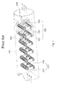
WO 2010/114332 A2 by LG ELECTRONICS INC., describes a solution (shown inFig. 1 of the present application) which allows integrating into a single heater both a heater for heating a drying air flow and a steam generator for treating laundry items. - A well-known problem of a steam generator like the one described in the above-mentioned patent application is the formation of calcareous deposits in the
coil duct 330 when non-demineralized water is vaporized therein. - The present invention aims at solving these and other problems by providing a drying or washing/drying machine comprising means for steam treatment of laundry items.
- Furthermore, the present invention aims at solving these and other problems by providing a method for drying laundry items which comprises at least one steam treatment step wherein vaporized condensed water is used.
- The idea at the basis of the present invention is to generate steam by using condensed water coming from the laundry drying process, so as to prevent the drying or washing/ drying machine from having to use water from the mains.
- In fact, the water coming from the mains normally contains a more or less large quantity of limestone, which will deposit onto the walls of the coil duct during the water vaporization process, thus impairing and/or preventing the operation of said coil duct.
- Further advantageous features of the present invention will be set out in the appended claims.
- These features as well as further advantages of the present invention will become more apparent from the following description of an embodiment thereof as shown in the annexed figures, which are supplied by way of non-limiting example, wherein:
-
Fig. 1 is a perspective view of the heater described in documentWO 2010/114332 A2 by LG ELECTRONICS INC.; -
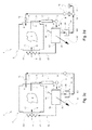
Fig. 2 shows a diagram of the machine according to the invention, which comprises a condensation and vaporization circuit; -
Fig. 2b shows a first variant of the diagram ofFig. 2 , which also includes a bottle for collecting condensed water; -
Fig. 2c shows a second variant of the diagram ofFig.2 , which includes a nozzle for nebulizing condensed water; -
Fig. 2d shows a third variant of the diagram ofFig.2 , which includes both the bottle of the first variant ofFig. 2b and the nozzle of the second variant ofFig. 2c ; -
Fig. 3 shows a detail of the diagram ofFig. 2 , concerning the condensation circuit; -
Fig. 4 is a perspective top view of a cross-flow thermal exchanger comprised in the machine ofFig. 2 . - With reference to
Fig. 2 , there is shown a drying or washing/drying machine 1 that comprises drying means, steam treatment means for treatinglaundry items 2, and a tub (not shown in the figures), inside of which arotary drum 3 is positioned, into whichdrum laundry items 2 can be placed for subjecting them to a drying process; said tub comprises anfront access door 4, through whichlaundry items 2 can be loaded into or unloaded from thedrum 3, aninlet 5 for a drying flow of dryhot air 51, an inlet for steam 6, arranged at the rear of the tub, and an outlet 7 for a flow of humidhot air 71. - The drying means comprise a
heater 8, preferably arranged near the back of the tub, which comprises heating means, preferably of the electric type, capable of both increasing the temperature of a drycold air flow 52 and vaporizing a water flow; saidheater 8 further comprises acold air inlet 81, ahot air outlet 82, awater inlet 83 and asteam outlet 84. - Through the
inlet 81, theheater 8 receives the drycold air flow 52, which, by lapping heating means, preferably consisting of electric resistors, produces the drying flow of dryhot air 51, which in turn flows out through thehot air outlet 82; saidhot air duct 82 is put in fluidic communication with the tub of the drying or washing/ drying machine by means of theinlet 5. - The
cold air inlet 81 may be put in fluidic communication with the outside environment or, more preferably, with condensing means. In this latter case, also the outlet 7 will have to be put in fluidic communication with said condensing means, as opposed to the outside environment, thus advantageously preventing the moisture from being dispersed in the surrounding environment. This aspect is important when the machine is to be installed in a house, in that this avoids adversely affecting the comfort of the surrounding environment. - With reference also to
Figs. 3 and4 , the condensing means comprise athermal exchanger 9, preferably of the cross-flow type, and atank 10 for collecting condensed water generated by condensation of moisture present in the flow of humidhot air 71. - The
thermal exchanger 9 comprises a humidhot air inlet 91 for theair flow 71, a drycold air outlet 92 for theair flow 52, a coldcooling air inlet 93 for acooling air flow 96, acondensate drain 94, through which a condensedwater flow 98 is collected, and ahot air outlet 95 for a heatedair flow 97. - The humid
hot air inlet 91 is in fluidic communication with the tub outlet 7 through an extraction duct (not shown in the figures), whereas the drycold air outlet 92 is in fluidic communication with thetub inlet 5 through an intake duct (not shown in the figures). - Along the extraction duct a
fan 12 is installed, which speeds up the circulation of the air flows in the extraction and intake ducts. - Also along the extraction duct, preferably upstream of the
fan 12, one may advantageously install ananti-lint filter 11 for trapping any lint produced by thelaundry items 2 during the drying treatment. - The cold
cooling air inlet 93 and thehot air outlet 95 are both in fluidic communication with the outside environment and, for the purpose of advantageously increasing the efficiency of thethermal exchanger 9, the velocity of thecooling air flow 96 may advantageously be increased by using anexternal fan 13. - The
condensate drain 94 is in fluidic communication with thetank 10 through a condensate duct (not shown in the figures), by means of which the condensedwater flow 98 arrives at and is collected in thetank 10. Thetank 10 comprises anoutlet 101 in fluidic communication with the steam treatment means; saidtank 10 is advantageously positioned near thethermal exchanger 9, preferably under it, so as to make the condensate easier to collect by gravity. - The steam treatment means comprise the
heater 8 and apump 14, the latter comprising an intake duct and a delivery duct. Theoutlet 101 of thetank 10 is put in fluidic communication with the intake duct of thepump 14 by means of a condensed water duct (not shown in the figures), and thedelivery duct 14 is in fluidic communication with thewater inlet 83 of theheater 8. - By using condensed water by means of the
tank 10, saidtank 10 needs not be filled before every drying cycle, and therefore it can advantageously be placed in the rear part of the drying or washing/drying machine, near theheater 8. In this configuration, due to the dispersed heat irradiated by theheater 8, the temperature of the water contained in thetank 10 is advantageously higher than ambient temperature. - When the steam treatment means are in operation, the action of the
heater 8 vaporizes the water flow, thus transforming it into a steam flow, which exits through thesteam outlet 84. - It must be pointed out that the
heater 8 keeps the water/steam and air flows separate by using a water vaporization duct (not shown in the figures); said vaporization duct contacts the heating means of the heater, thereby advantageously heating the condensed water, which, since it substantially contains no dissolved limestone, will leave no calcareous deposits onto the inner surface of said vaporization duct. - Also, this configuration of the
heater 8 allows the drying means and the steam treatment means to operate independently of each other, thus making it possible to provide specific drying and sanitizing cycles forlaundry items 2 of different types. - A first variant is shown in
Fig. 2b , wherein the above-described drying or washing/drying machine 1 further comprises atransfer pump 16 positioned downstream of thetank 10; saidtransfer pump 16 can transfer the condensed water, whether simultaneously or alternately, into areservoir 17 and/or abottle 18. - The
reservoir 17 is in fluidic communication with the intake duct of thepump 14, thus acting as a storage unit and advantageously preventing any air from entering thepump 14. This will increase the operating life of thepump 14. - Finally, the
bottle 18 collects the condensed water during and/or at the end of the process of drying thelaundry items 2, and saidbottle 18 may advantageously be separated from the machine 1 for being emptied, thus making it unnecessary to connect the machine 1 to a drain mains. - A second variant is shown in
Fig. 2c , wherein the steam treatment means comprise nebulization/atomization means, which in turn comprisee nebulization nozzle 15 and apump 14 comprising an intake duct, a delivery duct and an air/water mixer, if mist is to be generated by atomization of water molecules. - Just like the main embodiment, the
outlet 101 of thetank 10 is put in fluidic communication with the intake duct of thepump 14 by means of the condensed water duct (not shown in the figures), whereas the delivery side, unlike the main embodiment, is put in fluidic communication with thenebulization nozzle 15 by means of a high-pressure duct (not shown in the figures), since the pressures involved may be in the range of 50 bar to 200 bar, preferably 100 bar to 150 bar. The combined action of thepump 14 andnozzle 15 allows to nebulize/atomize the water into droplets forming a flow of nebulized water or mist. - The end portion of the
nozzle 15 is put in fluidic communication with the atomized/nebulized water inlet 6 of the tub through a water/mist duct (not shown in the figures). - When the steam treatment means are in operation, the flow of nebulized water or mist is delivered into the tub and then vaporized by the high air temperature caused by the drying flow of dry hot air.
- Finally, a third variant is shown in
Fig. 2d , wherein the machine 1 additionally comprises, compared to the above-described variant, thetransfer pump 16, thereservoir 17 and the bottle 18 (like those of the first variant), wherein thetransfer pump 16 can transfer the condensed water, whether simultaneously or alternately, into thereservoir 17 and/or thebottle 18. This combines the advantages obtainable from the first variant with those of the second variant. - In conclusion, the machine 1 can treat
laundry items 2 in accordance with a drying method that comprises a steam treatment step A and a drying step B, wherein the steam treatment step A uses vaporized condensed water to sanitize and stretch the fibers of thelaundry items 2, and wherein the condensed water is generated during the drying step B; said step A is carried out before, during or after the drying step B. - Of course, the example described herein may be subject to further variations, which will nonetheless still fall within the scope of the following claims.
Claims (15)
- A drying or washing/drying machine (1) for treating laundry items (2), comprising a tub, inside of which a rotary drum (3) is positioned, and steam treatment means for sanitizing and stretching the fibers of the laundry items (2),
characterized in that
the steam treatment means vaporize condensed water. - A machine (1) according to claim 1, wherein the steam treatment means comprise a heater (8) and a pump (14) that comprises an intake duct and a delivery duct, wherein the condensed water flows through the intake duct, and the delivery duct is in fluidic communication with the heater (8).
- A machine (1) according to claim 2, further comprising condensing means which in turn comprise an outlet for dry cold air (92) and an inlet for humid hot air (91), wherein the latter are placed in fluidic communication with the heater (8) and with the tub, respectively, so as to condense excess moisture contained in a humid hot air flow (71) coming from said tub following a laundry drying process.
- A machine (1) according to claim 3, wherein the condensing means comprise a thermal exchanger (9) and a tank (10) for collecting a condensed water flow (98) caused by condensation of the excess moisture contained in the humid hot air flow (71).
- A machine (1) according to claim 4, wherein the condensing means further comprise a transfer pump (16) positioned downstream of the tank (10), and wherein said transfer pump (16) can transfer the condensed water, whether simultaneously or alternately, into a reservoir (17) and/or a bottle (18).
- A machine (1) according to claim 5, wherein the bottle (18) can advantageously be separated from the machine (1) for being emptied, thus making it unnecessary to connect the machine (1) to a drain mains.
- A machine (1) according to any one of claims 4 to 6, wherein the thermal exchanger (9) is of the cross-flow type.
- A machine (1) according to claim 7, wherein the thermal exchanger (9) comprises the humid hot air inlet (91), the dry cold air outlet (92), an inlet for cold cooling air (93), a drain for condensed water (94) and an outlet for hot air (95), respectively for the humid hot air flow (71), the dry cold air flow (52), a cooling air flow (96), the condensed water flow (98) and a heated air flow (97).
- A machine (1) according to claim 8, wherein the velocity of the cooling air flow (96) can advantageously be increased by using an external fan (13).
- A machine (1) according to any one of claims 4 to 9, wherein the water flow entering the vaporization means comes from the tank (10) positioned near the thermal exchanger (9).
- A machine (1) according to any one of claims 5 to 9, wherein the water flow entering the vaporization means comes from the reservoir (17), which, by acting as a storage unit, advantageously prevents any air from entering the pump (14).
- A method for drying laundry items (2), comprising a steam treatment step (A) and a drying step (B),
characterized in that
said steam treatment step (A) utilizes vaporized condensed water to sanitize and stretch the fibers of the laundry items (2), and wherein said condensed water is generated during the drying step (B). - A method according to claim 12, wherein the steam treatment step (A) is carried out before, during or after said drying step (B).
- A machine according to any one of claims 1 to 11, further comprising a heater (8), and wherein the steam treatment means also comprise nebulization/atomization means that nebulize/atomize condensed water, which is then vaporized inside the tub by means of the heat generated by the heater (8).
- A method for drying laundry items (2), comprising a steam treatment step (A) and a drying step (B),
characterized in that
said steam treatment step (A) utilizes condensed water which is nebulized/atomized and subsequently vaporized to sanitize and stretch the fibers of the laundry items (2), and wherein said condensed water is generated during the drying step (B).
Applications Claiming Priority (2)
| Application Number | Priority Date | Filing Date | Title |
|---|---|---|---|
| IT000813A ITTO20110813A1 (en) | 2011-09-12 | 2011-09-12 | DRYING MACHINE OR WASHING MACHINE INCLUDING VEHICLES FOR THE TREATMENT OF CLOTHS THROUGH THE USE OF CONDENSED WATER OR SPRAYED OR ATOMIZED |
| IT000812A ITTO20110812A1 (en) | 2011-09-12 | 2011-09-12 | DRYING MACHINE OR WASHING MACHINE INCLUDING VEHICLES FOR THE TREATMENT OF CLOTHS THROUGH THE USE OF STEAMED CONDENSATE WATER |
Publications (1)
| Publication Number | Publication Date |
|---|---|
| EP2568075A1 true EP2568075A1 (en) | 2013-03-13 |
Family
ID=46758694
Family Applications (1)
| Application Number | Title | Priority Date | Filing Date |
|---|---|---|---|
| EP12183411A Withdrawn EP2568075A1 (en) | 2011-09-12 | 2012-09-07 | Drying or washing/drying machine comprising means for treating laundry items by using vaporized condensed water |
Country Status (1)
| Country | Link |
|---|---|
| EP (1) | EP2568075A1 (en) |
Cited By (2)
| Publication number | Priority date | Publication date | Assignee | Title |
|---|---|---|---|---|
| CN114543063A (en) * | 2020-11-27 | 2022-05-27 | 广东美的环境电器制造有限公司 | Steam generating device and steam equipment |
| CN114543064A (en) * | 2020-11-27 | 2022-05-27 | 广东美的环境电器制造有限公司 | Steam generating device and steam equipment |
Citations (5)
| Publication number | Priority date | Publication date | Assignee | Title |
|---|---|---|---|---|
| EP1441060A1 (en) * | 2003-01-25 | 2004-07-28 | Electrolux Home Products Corporation N.V. | Laundry dryer with a device for spraying additives and method therefor |
| EP1887127A1 (en) * | 2006-08-08 | 2008-02-13 | Electrolux Home Products Corporation N.V. | Laundry treating machine |
| EP1990466A1 (en) * | 2007-05-11 | 2008-11-12 | Electrolux Home Products Corporation N.V. | Improved laundry dryer with refreshment operation |
| US20100086287A1 (en) * | 2008-10-03 | 2010-04-08 | Euro-Pro Operating Llc | Apparatus and method for a steamer |
| WO2010114332A2 (en) | 2009-04-02 | 2010-10-07 | (주)엘지전자 | Clothes dryer having a steam generator using a hot air heater |
-
2012
- 2012-09-07 EP EP12183411A patent/EP2568075A1/en not_active Withdrawn
Patent Citations (5)
| Publication number | Priority date | Publication date | Assignee | Title |
|---|---|---|---|---|
| EP1441060A1 (en) * | 2003-01-25 | 2004-07-28 | Electrolux Home Products Corporation N.V. | Laundry dryer with a device for spraying additives and method therefor |
| EP1887127A1 (en) * | 2006-08-08 | 2008-02-13 | Electrolux Home Products Corporation N.V. | Laundry treating machine |
| EP1990466A1 (en) * | 2007-05-11 | 2008-11-12 | Electrolux Home Products Corporation N.V. | Improved laundry dryer with refreshment operation |
| US20100086287A1 (en) * | 2008-10-03 | 2010-04-08 | Euro-Pro Operating Llc | Apparatus and method for a steamer |
| WO2010114332A2 (en) | 2009-04-02 | 2010-10-07 | (주)엘지전자 | Clothes dryer having a steam generator using a hot air heater |
Cited By (2)
| Publication number | Priority date | Publication date | Assignee | Title |
|---|---|---|---|---|
| CN114543063A (en) * | 2020-11-27 | 2022-05-27 | 广东美的环境电器制造有限公司 | Steam generating device and steam equipment |
| CN114543064A (en) * | 2020-11-27 | 2022-05-27 | 广东美的环境电器制造有限公司 | Steam generating device and steam equipment |
Similar Documents
| Publication | Publication Date | Title |
|---|---|---|
| US11585032B2 (en) | Laundry treating appliance and method of operation | |
| CN102471986B (en) | Apparatus for drying clothes | |
| RU2661812C2 (en) | Household laundry dryer | |
| KR101435810B1 (en) | Apparatus for processing clothes | |
| US20070006484A1 (en) | Clothes dryer and method for removing odours from textiles | |
| CN103348053A (en) | Appliance for drying laundry | |
| US20120047662A1 (en) | Laundry treatment device having a steam generator and method for treating items to be washed | |
| KR20110123344A (en) | Drying device | |
| EP2568074B1 (en) | Drying or washing/drying machine comprising a door containing means for generating steam for treating laundry items | |
| EP2642012A1 (en) | Laundry machine and method of laundry treatment in a laundry machine | |
| ES2225444T3 (en) | STEAM IRONING DEVICE WITH ADDITIVES. | |
| KR101430459B1 (en) | Apparatus for processing clothes | |
| US8353115B2 (en) | Exhaust air dryer with a heat exchanger | |
| WO2020064254A1 (en) | A heat pump dishwasher comprising an evaporator tray | |
| KR101199395B1 (en) | drying device | |
| US20120137536A1 (en) | Appliance for drying laundry | |
| EP3149237B1 (en) | Laundry treatment appliance with a condensate water lint disintegration unit | |
| KR101023907B1 (en) | Dryer with liquid material injection means | |
| KR20100089381A (en) | Dryer with fluid injection means | |
| ITTO20110813A1 (en) | DRYING MACHINE OR WASHING MACHINE INCLUDING VEHICLES FOR THE TREATMENT OF CLOTHS THROUGH THE USE OF CONDENSED WATER OR SPRAYED OR ATOMIZED | |
| KR20060067215A (en) | Condensate drainage system for clothes dryer | |
| CN103668890B (en) | The method for regenerating solvent of dry cleaner | |
| KR20230075749A (en) | Steamer and apparatus for supplying steam thereof | |
| ITTO20110812A1 (en) | DRYING MACHINE OR WASHING MACHINE INCLUDING VEHICLES FOR THE TREATMENT OF CLOTHS THROUGH THE USE OF STEAMED CONDENSATE WATER |
Legal Events
| Date | Code | Title | Description |
|---|---|---|---|
| PUAI | Public reference made under article 153(3) epc to a published international application that has entered the european phase |
Free format text: ORIGINAL CODE: 0009012 |
|
| AK | Designated contracting states |
Kind code of ref document: A1 Designated state(s): AL AT BE BG CH CY CZ DE DK EE ES FI FR GB GR HR HU IE IS IT LI LT LU LV MC MK MT NL NO PL PT RO RS SE SI SK SM TR |
|
| AX | Request for extension of the european patent |
Extension state: BA ME |
|
| 17P | Request for examination filed |
Effective date: 20130913 |
|
| RBV | Designated contracting states (corrected) |
Designated state(s): AL AT BE BG CH CY CZ DE DK EE ES FI FR GB GR HR HU IE IS IT LI LT LU LV MC MK MT NL NO PL PT RO RS SE SI SK SM TR |
|
| RAP1 | Party data changed (applicant data changed or rights of an application transferred) |
Owner name: WHIRLPOOL EMEA S.P.A |
|
| 17Q | First examination report despatched |
Effective date: 20170412 |
|
| STAA | Information on the status of an ep patent application or granted ep patent |
Free format text: STATUS: THE APPLICATION IS DEEMED TO BE WITHDRAWN |
|
| 18D | Application deemed to be withdrawn |
Effective date: 20190402 |