EP2567772A2 - Friction bonding structure and pump device - Google Patents
Friction bonding structure and pump device Download PDFInfo
- Publication number
- EP2567772A2 EP2567772A2 EP12182780A EP12182780A EP2567772A2 EP 2567772 A2 EP2567772 A2 EP 2567772A2 EP 12182780 A EP12182780 A EP 12182780A EP 12182780 A EP12182780 A EP 12182780A EP 2567772 A2 EP2567772 A2 EP 2567772A2
- Authority
- EP
- European Patent Office
- Prior art keywords
- sliding contact
- friction
- protrusions
- storage portion
- members
- Prior art date
- Legal status (The legal status is an assumption and is not a legal conclusion. Google has not performed a legal analysis and makes no representation as to the accuracy of the status listed.)
- Withdrawn
Links
Images




Classifications
-
- B—PERFORMING OPERATIONS; TRANSPORTING
- B23—MACHINE TOOLS; METAL-WORKING NOT OTHERWISE PROVIDED FOR
- B23K—SOLDERING OR UNSOLDERING; WELDING; CLADDING OR PLATING BY SOLDERING OR WELDING; CUTTING BY APPLYING HEAT LOCALLY, e.g. FLAME CUTTING; WORKING BY LASER BEAM
- B23K20/00—Non-electric welding by applying impact or other pressure, with or without the application of heat, e.g. cladding or plating
- B23K20/12—Non-electric welding by applying impact or other pressure, with or without the application of heat, e.g. cladding or plating the heat being generated by friction; Friction welding
- B23K20/129—Non-electric welding by applying impact or other pressure, with or without the application of heat, e.g. cladding or plating the heat being generated by friction; Friction welding specially adapted for particular articles or work
-
- B—PERFORMING OPERATIONS; TRANSPORTING
- B29—WORKING OF PLASTICS; WORKING OF SUBSTANCES IN A PLASTIC STATE IN GENERAL
- B29C—SHAPING OR JOINING OF PLASTICS; SHAPING OF MATERIAL IN A PLASTIC STATE, NOT OTHERWISE PROVIDED FOR; AFTER-TREATMENT OF THE SHAPED PRODUCTS, e.g. REPAIRING
- B29C65/00—Joining or sealing of preformed parts, e.g. welding of plastics materials; Apparatus therefor
- B29C65/02—Joining or sealing of preformed parts, e.g. welding of plastics materials; Apparatus therefor by heating, with or without pressure
- B29C65/06—Joining or sealing of preformed parts, e.g. welding of plastics materials; Apparatus therefor by heating, with or without pressure using friction, e.g. spin welding
- B29C65/0672—Spin welding
-
- B—PERFORMING OPERATIONS; TRANSPORTING
- B29—WORKING OF PLASTICS; WORKING OF SUBSTANCES IN A PLASTIC STATE IN GENERAL
- B29C—SHAPING OR JOINING OF PLASTICS; SHAPING OF MATERIAL IN A PLASTIC STATE, NOT OTHERWISE PROVIDED FOR; AFTER-TREATMENT OF THE SHAPED PRODUCTS, e.g. REPAIRING
- B29C66/00—General aspects of processes or apparatus for joining preformed parts
- B29C66/01—General aspects dealing with the joint area or with the area to be joined
- B29C66/05—Particular design of joint configurations
- B29C66/10—Particular design of joint configurations particular design of the joint cross-sections
- B29C66/12—Joint cross-sections combining only two joint-segments; Tongue and groove joints; Tenon and mortise joints; Stepped joint cross-sections
- B29C66/124—Tongue and groove joints
-
- B—PERFORMING OPERATIONS; TRANSPORTING
- B29—WORKING OF PLASTICS; WORKING OF SUBSTANCES IN A PLASTIC STATE IN GENERAL
- B29C—SHAPING OR JOINING OF PLASTICS; SHAPING OF MATERIAL IN A PLASTIC STATE, NOT OTHERWISE PROVIDED FOR; AFTER-TREATMENT OF THE SHAPED PRODUCTS, e.g. REPAIRING
- B29C66/00—General aspects of processes or apparatus for joining preformed parts
- B29C66/01—General aspects dealing with the joint area or with the area to be joined
- B29C66/32—Measures for keeping the burr form under control; Avoiding burr formation; Shaping the burr
- B29C66/322—Providing cavities in the joined article to collect the burr
-
- B—PERFORMING OPERATIONS; TRANSPORTING
- B29—WORKING OF PLASTICS; WORKING OF SUBSTANCES IN A PLASTIC STATE IN GENERAL
- B29C—SHAPING OR JOINING OF PLASTICS; SHAPING OF MATERIAL IN A PLASTIC STATE, NOT OTHERWISE PROVIDED FOR; AFTER-TREATMENT OF THE SHAPED PRODUCTS, e.g. REPAIRING
- B29C66/00—General aspects of processes or apparatus for joining preformed parts
- B29C66/50—General aspects of joining tubular articles; General aspects of joining long products, i.e. bars or profiled elements; General aspects of joining single elements to tubular articles, hollow articles or bars; General aspects of joining several hollow-preforms to form hollow or tubular articles
- B29C66/51—Joining tubular articles, profiled elements or bars; Joining single elements to tubular articles, hollow articles or bars; Joining several hollow-preforms to form hollow or tubular articles
- B29C66/54—Joining several hollow-preforms, e.g. half-shells, to form hollow articles, e.g. for making balls, containers; Joining several hollow-preforms, e.g. half-cylinders, to form tubular articles
- B29C66/542—Joining several hollow-preforms, e.g. half-shells, to form hollow articles, e.g. for making balls, containers; Joining several hollow-preforms, e.g. half-cylinders, to form tubular articles joining hollow covers or hollow bottoms to open ends of container bodies
-
- F—MECHANICAL ENGINEERING; LIGHTING; HEATING; WEAPONS; BLASTING
- F01—MACHINES OR ENGINES IN GENERAL; ENGINE PLANTS IN GENERAL; STEAM ENGINES
- F01C—ROTARY-PISTON OR OSCILLATING-PISTON MACHINES OR ENGINES
- F01C21/00—Component parts, details or accessories not provided for in groups F01C1/00 - F01C20/00
- F01C21/10—Outer members for co-operation with rotary pistons; Casings
-
- B—PERFORMING OPERATIONS; TRANSPORTING
- B29—WORKING OF PLASTICS; WORKING OF SUBSTANCES IN A PLASTIC STATE IN GENERAL
- B29C—SHAPING OR JOINING OF PLASTICS; SHAPING OF MATERIAL IN A PLASTIC STATE, NOT OTHERWISE PROVIDED FOR; AFTER-TREATMENT OF THE SHAPED PRODUCTS, e.g. REPAIRING
- B29C66/00—General aspects of processes or apparatus for joining preformed parts
- B29C66/70—General aspects of processes or apparatus for joining preformed parts characterised by the composition, physical properties or the structure of the material of the parts to be joined; Joining with non-plastics material
- B29C66/71—General aspects of processes or apparatus for joining preformed parts characterised by the composition, physical properties or the structure of the material of the parts to be joined; Joining with non-plastics material characterised by the composition of the plastics material of the parts to be joined
-
- B—PERFORMING OPERATIONS; TRANSPORTING
- B29—WORKING OF PLASTICS; WORKING OF SUBSTANCES IN A PLASTIC STATE IN GENERAL
- B29L—INDEXING SCHEME ASSOCIATED WITH SUBCLASS B29C, RELATING TO PARTICULAR ARTICLES
- B29L2031/00—Other particular articles
- B29L2031/748—Machines or parts thereof not otherwise provided for
- B29L2031/749—Motors
-
- F—MECHANICAL ENGINEERING; LIGHTING; HEATING; WEAPONS; BLASTING
- F01—MACHINES OR ENGINES IN GENERAL; ENGINE PLANTS IN GENERAL; STEAM ENGINES
- F01C—ROTARY-PISTON OR OSCILLATING-PISTON MACHINES OR ENGINES
- F01C19/00—Sealing arrangements in rotary-piston machines or engines
- F01C19/005—Structure and composition of sealing elements such as sealing strips, sealing rings and the like; Coating of these elements
-
- F—MECHANICAL ENGINEERING; LIGHTING; HEATING; WEAPONS; BLASTING
- F04—POSITIVE - DISPLACEMENT MACHINES FOR LIQUIDS; PUMPS FOR LIQUIDS OR ELASTIC FLUIDS
- F04C—ROTARY-PISTON, OR OSCILLATING-PISTON, POSITIVE-DISPLACEMENT MACHINES FOR LIQUIDS; ROTARY-PISTON, OR OSCILLATING-PISTON, POSITIVE-DISPLACEMENT PUMPS
- F04C15/00—Component parts, details or accessories of machines, pumps or pumping installations, not provided for in groups F04C2/00 - F04C14/00
- F04C15/0003—Sealing arrangements in rotary-piston machines or pumps
- F04C15/0034—Sealing arrangements in rotary-piston machines or pumps for other than the working fluid, i.e. the sealing arrangements are not between working chambers of the machine
-
- F—MECHANICAL ENGINEERING; LIGHTING; HEATING; WEAPONS; BLASTING
- F04—POSITIVE - DISPLACEMENT MACHINES FOR LIQUIDS; PUMPS FOR LIQUIDS OR ELASTIC FLUIDS
- F04C—ROTARY-PISTON, OR OSCILLATING-PISTON, POSITIVE-DISPLACEMENT MACHINES FOR LIQUIDS; ROTARY-PISTON, OR OSCILLATING-PISTON, POSITIVE-DISPLACEMENT PUMPS
- F04C2/00—Rotary-piston machines or pumps
- F04C2/08—Rotary-piston machines or pumps of intermeshing-engagement type, i.e. with engagement of co-operating members similar to that of toothed gearing
- F04C2/10—Rotary-piston machines or pumps of intermeshing-engagement type, i.e. with engagement of co-operating members similar to that of toothed gearing of internal-axis type with the outer member having more teeth or tooth-equivalents, e.g. rollers, than the inner member
-
- F—MECHANICAL ENGINEERING; LIGHTING; HEATING; WEAPONS; BLASTING
- F04—POSITIVE - DISPLACEMENT MACHINES FOR LIQUIDS; PUMPS FOR LIQUIDS OR ELASTIC FLUIDS
- F04C—ROTARY-PISTON, OR OSCILLATING-PISTON, POSITIVE-DISPLACEMENT MACHINES FOR LIQUIDS; ROTARY-PISTON, OR OSCILLATING-PISTON, POSITIVE-DISPLACEMENT PUMPS
- F04C2230/00—Manufacture
- F04C2230/20—Manufacture essentially without removing material
-
- F—MECHANICAL ENGINEERING; LIGHTING; HEATING; WEAPONS; BLASTING
- F04—POSITIVE - DISPLACEMENT MACHINES FOR LIQUIDS; PUMPS FOR LIQUIDS OR ELASTIC FLUIDS
- F04C—ROTARY-PISTON, OR OSCILLATING-PISTON, POSITIVE-DISPLACEMENT MACHINES FOR LIQUIDS; ROTARY-PISTON, OR OSCILLATING-PISTON, POSITIVE-DISPLACEMENT PUMPS
- F04C2230/00—Manufacture
- F04C2230/60—Assembly methods
-
- F—MECHANICAL ENGINEERING; LIGHTING; HEATING; WEAPONS; BLASTING
- F04—POSITIVE - DISPLACEMENT MACHINES FOR LIQUIDS; PUMPS FOR LIQUIDS OR ELASTIC FLUIDS
- F04C—ROTARY-PISTON, OR OSCILLATING-PISTON, POSITIVE-DISPLACEMENT MACHINES FOR LIQUIDS; ROTARY-PISTON, OR OSCILLATING-PISTON, POSITIVE-DISPLACEMENT PUMPS
- F04C2230/00—Manufacture
- F04C2230/70—Disassembly methods
-
- Y—GENERAL TAGGING OF NEW TECHNOLOGICAL DEVELOPMENTS; GENERAL TAGGING OF CROSS-SECTIONAL TECHNOLOGIES SPANNING OVER SEVERAL SECTIONS OF THE IPC; TECHNICAL SUBJECTS COVERED BY FORMER USPC CROSS-REFERENCE ART COLLECTIONS [XRACs] AND DIGESTS
- Y10—TECHNICAL SUBJECTS COVERED BY FORMER USPC
- Y10T—TECHNICAL SUBJECTS COVERED BY FORMER US CLASSIFICATION
- Y10T403/00—Joints and connections
- Y10T403/47—Molded joint
- Y10T403/477—Fusion bond, e.g., weld, etc.
Definitions
- the invention relates to a friction bonding structure and a pump device.
- JP 2005-81351 A describes that a storage portion for storing burrs is formed near a friction bonded portion.
- FIG. 11 and FIG. 12 show a related art.
- FIG. 11 is a sectional view that shows a conventional friction bonding structure.
- FIG. 12 is a sectional view taken along the line B-B in FIG. 11 .
- a lid 61 formed in a disc shape is attached to an open end 60a of a cylinder 60 formed in a generally cylindrical shape, and the lid 61 and the cylinder 60 are frictionally bonded together.
- An annular groove 62 is formed at the open end 60a of the cylinder 60.
- a sliding contact projection 63 in an annular plate shape is formed on the lid 61. The sliding contact projection 63 corresponds to the annular groove 62.
- annular storage portions 69 are formed between the sliding contact projection 63 and the wall portions 66, 67. Burrs 68 produced at the friction bonded portion 65 are stored in the storage portions 69. In this example, because most of the produced burrs 68 stick out from the friction bonded portion 65 radially outward, an outer storage portion 69a, which is one of the storage portions 69, is set wider than the other one of the storage portions 69.
- a narrow-width portion S is formed in the thus formed storage portion 69 depending on the roundness of the sliding contact projection 63 and the annular groove 62 or the coaxiality between the sliding contact projection 63 and the annular groove 62. If the burrs 68 accumulate at the narrow-width portion S, the burrs 68 stick out of the storage portion 69 (69a).
- the size of the storage portion 69 (69a) may be increased or the meltage may be optimized to suppress production of the burrs 68.
- an increase in the size of the storage portion 69 causes an increase in the size of a device.
- the invention provides a friction bonding structure and a pump device with which the sticking-out of burrs is suppressed without the need for an increase in the size of a storage portion or strict tolerance management.
- a plurality of partitioning elements that partition a storage portion in the circumferential direction to disperse burrs in the circumferential direction.
- the electric pump device 1 includes a pump mechanism (gear pump) 3 and a pump plate 4.
- the pump mechanism 3 is accommodated in a pump case 2.
- the pump plate 4 is attached to one end (left-side end face 2a in FIG. 1 ) of the pump case 2, and constitutes a suction portion and discharge portion of the pump mechanism 3.
- a motor case 5 formed in a generally cylindrical shape is fixed to the other end (right-side end face 2b in FIG. 1 ) of the pump case 2, and accommodates a motor 6 that serves as a drive source and a control board 7 for the motor 6.
- a cover 8 formed in a generally disc shape is attached to an open end 5a of the motor case 5.
- the motor case 5 is integrally formed with a stator 10 of the motor 6 by resin molding.
- the control board 7 is accommodated in the motor case 5, at a position near the open end 5a.
- a cylindrical support portion 11 is coaxially arranged inside the cylindrical motor case 5.
- the support portion 11 is formed to project from the end face 2b of the pump case 2.
- a rotor 12 of the motor 6 is fixed to a motor shaft 13 that is passed through the support portion 11. As a result, the rotor 12 is arranged radially inward of the stator 10.
- the motor shaft 13 is rotatably supported by a bearing 14 provided at the support portion 11.
- the rotor 12 is formed in a closed-end cylindrical shape, and is arranged in the cylindrical motor case 5 so as to surround the radially outer side of the support portion 11.
- One end of the motor shaft 13 is fixed to a bottom 12a of the rotor 12.
- the rotor 12 is coupled to an inner gear 3a of the pump mechanism 3 via the motor shaft 13.
- the cover 8 in the present embodiment is made of resin (e.g. polyamide).
- the cover 8 is frictionally bonded to the open end 5a of the motor case 5. In this way, the liquid-tightness of the inside of the cylindrical motor case 5 is ensured.
- annular groove 21 is formed at the open end 5a of the motor case 5.
- the annular groove 21 is open in the axial direction (upward in FIG. 2 ).
- a sliding contact projection 22 in an annular plate shape is formed on a mounting surface 8a of the cover 8.
- the sliding contact projection 22 corresponds to the annular groove 21.
- the cover 8 is attached to the open end 5a of the motor case 5 by inserting the sliding contact projection 22 of the cover 8 into the annular groove 21 and bringing the distal end of the sliding contact projection 22 into contact with a bottom 23 of the annular groove 21.
- the cover 8 is rotated with the sliding contact projection 22 in contact with the bottom 23 of the annular groove 21.
- the motor case 5 is fixed so as to be non-rotatable. Then, by rotating the cover 8 relative to the motor case 5, the cover 8 is frictionally bonded (spin-welded) to the open end 5a of the motor case 5.
- a melting portion 24 is formed at the distal end of the sliding contact projection 22.
- the melting portion 24 is formed such that the width of the melting portion 24 is smaller than that of the other portion of the sliding contact projection 22.
- the melting portion 24 and the bottom 23 of the annular groove 21, which are melted by the frictional heat, are welded to each other. As a result, an annular friction bonded portion 25 is formed.
- Wall portions 26, 27 of the annular groove 21 are arranged so as to be coaxial with the friction bonded portion 25.
- clearances formed between the wall portions 26, 27, which may function as annular walls, and the friction bonded portion 25 are used as storage portions 28, and products of melting, which stick out from the friction bonded portion 25, that is, "burrs", are stored in the storage portions 28.
- a plurality of protrusions 29 is formed on the sliding contact projection 22.
- the protrusions 29 protrude from the sliding contact projection 22 radially outward.
- each protrusion 29 is formed in a plate-shape, and extends in the axial direction.
- the protrusions 29 are arranged in the annular groove 21 together with the sliding contact projection 22 that will be the friction bonded portion 25.
- a storage portion 28a which is one of the storage portions 28 and which is formed between the sliding contact projection 22 and the wall portion 26 that surrounds the radially outer side of the sliding contact projection 22, is partitioned in the circumferential direction by the protrusions 29.
- burrs 30 produced at the friction bonded portion 25 adhere to the corresponding protrusions 29, located downstream of burr produced points in the rotation direction, as the sliding contact projection 22 (cover 8) rotates (in the counterclockwise direction in the example shown in FIG. 5 ).
- the burrs 30 adhere to the protrusions 29, which may function as partitioning elements, and therefore the burrs 30 are stored in the storage portion 28a while being dispersed in the circumferential direction.
- the motor case 5 and the cover 8 both are made of resin. Therefore, the burrs 30 produced through melting of resin tend to be light and bulky. Therefore, the burrs 30 tend to revolve inside the storage portions 28 due to the rotation of the cover 8, and the sticking-out of the burrs 30 to the outside of the storage portion 28a tends to occur due to the accumulation of the burrs 30. Therefore, by applying the configuration according to the present embodiment, it is possible to obtain remarkable advantageous effects. In addition, such friction bonding between resin members is widely adopted for cases of electronic devices because a melting temperature of resin is low.
- the partitioning elements are formed of the protrusions 29 formed on the sliding contact projection 22. Therefore, the protrusions 29, which may function as the partitioning elements, rotate together with the sliding contact projection 22. That is, the protrusions 29 are located next to the friction bonded portion 25, so the produced burrs 30 easily adhere to the protrusions 29. As a result, it is possible to disperse the burrs 30 in the storage portion 28a in the circumferential direction.
- the protrusions 29 are formed to protrude radially outward from the sliding contact projection 22.
- the protrusion 29, which may function as the partitioning elements, are arranged in the storage portion 28a between the sliding contact projection 22 and the wall portion 26 that surrounds the radially outer side of the sliding contact projection 22.
- the burrs 30 produced at the friction bonded portion 25 mostly stick out from the friction bonded portion 25 radially outward by centrifugal force. Therefore, with the above configuration, it is possible to further effectively suppress the sticking-out of the burrs 30.
- a flange 35 is formed at a distal end 32a of a wall portion 32, which is one of wall portions 32, 33 of an annular groove 31 and which is located on the radially outer side (right side in FIG. 6 ) of the wall portion 33.
- the annular groove 31 is formed at the open end 5a of the motor case 5.
- the flange 35 extends radially inward (toward the left side in FIG. 6 ), and is formed along the entire circumference of the wall portion 32.
- the sticking-out of the burrs 30 occurs when the burrs 30 are accumulated along a wall face 32b of the wall portion 32 within the storage portion 28a and climb over the wall portion 32.
- the flange 35 that projects from the distal end 32a of the wall portion 32 into the storage portion 28a is formed to cover the upper side of the wall face 32b. In this way, the burrs 30 accumulated along the wall face 32b are retained within the storage portion 28a by the flange 35.
- the second embodiment described above it is possible to efficiently store the produced burrs 30 within the storage portion 28a. Therefore, it is possible to reduce the volume of the storage portion 28a by utilizing the high storage efficiency. Specifically, it is possible to make the depth of the annular groove 31 that forms the storage portion 28a less than the depth of the annular groove 21 in the first embodiment (make the height of the wall portion 32 less than the height of the wall portion 26 in the first embodiment). As a result, it is possible to further reduce the size of the storage portion.
- the invention is applied to the electric pump device 1, more specifically, the friction bonding structure for frictionally bonding the motor case 5 and the cover 8 together.
- the application of the invention is not limited to this. As long as two members are frictionally bonded together, the invention may be applied to any members. Therefore, the invention may be applied to, for example, a pump device that is driven through a pulley, or the like, or may be applied to a device other than a pump device.
- the protrusions 29 are formed on the sliding contact projection 22, and the storage portion 28 (28a) are partitioned in the circumferential direction by the protrusions 29 that may function as the partitioning elements.
- the invention is not limited to this configuration.
- a plurality of protrusions 44 that protrude radially inward is formed on a wall portion 42, which is one of wall portions 42, 43 of an annular groove 41 and which is located radially outward of the wall portion 43, and the storage portion 28 (28a) is partitioned in the circumferential direction by the protrusions 44 that may function as partitioning elements.
- the burrs 30 are stored in the storage portion 28 while being dispersed in the circumferential direction.
- the configuration in which the protrusions 29 are formed on the sliding contact projection 22 of the cover 8 as in the first and second embodiments has advantage over the configuration in the third embodiment, in that it is easy to form the protrusions 29 and it is possible to arrange the protrusions 29, which may function as the partitioning elements, at positions near the friction bonded portion 25 without contact between the protrusions 29 and the friction bonded portion 25.
- the distal ends of protrusions 47 which may function as partitioning elements, may be inclined in the direction of relative rotation between two members to be frictionally bonded together. Because the protrusions 47 are formed on the sliding contact projection 22 of the cover 8, the distal ends of the protrusions 47 are inclined in the rotation direction (counterclockwise direction in FIG. 8 ) of the cover 8. With this configuration, it is possible to further reliably cause the burrs 30 to adhere to the protrusions 47.
- protrusions which may function as partitioning elements
- the direction opposite to the rotation direction of the cover 8 is the "relative rotation direction”. Therefore, for example, if the configuration in the third embodiment shown in FIG. 7 is employed as the base configuration, the distal ends of the protrusions 44 need to be inclined in the clockwise direction.
- the protrusions (29, 44 or 47), which may function as partitioning elements, are arranged in the storage portion 28a located radially outward of the friction bonded portion 25.
- the invention is not limited to this configuration.
- a plurality of protrusions 51 that protrude radially inward is formed over all around a sliding contact projection 50.
- the storage portion 28b is partitioned in the circumferential direction by the protrusions 51 that may function as partitioning elements.
- partitioning elements are arranged in both the storage portions 28a, 28b located on the radially outward and inward of the friction bonded portion 25, respectively.
- a plurality of protrusions 53 and a plurality of protrusions 54 are formed radially outward and inward of a sliding contact projection 52, respectively.
- the storage portion 28a and the storage portion 28b located radially outward and inward of the friction bonded portion 25 are partitioned in the circumferential direction by the protrusions 53 and the protrusions 54, which may function as partitioning elements, respectively.
- a plurality of protrusions is formed on at least one of the wall portions of the annular groove so that at least one of partitioning elements arranged in the outer-side storage portion 28a and partitioning elements arranged in the inner-side storage portion 28b are formed of the protrusions formed on the at least one of the wall portions.
- friction bonding is performed by bringing the rotating cover 8 into sliding contact with the open end 5a of the motor case 5 in a fixed state.
- the invention is not limited to this configuration. As long as two members to be frictionally bonded together are allowed to rotate relative to each other while being in sliding contact with each other, any two members may be used.
- the annular groove 21 is formed at the open end 5a of the motor case 5, and thus the motor case 5 is used as a first member that has the wall portions 26, 27 as annular walls.
- the sliding contact projection 22 is formed on the cover 8 that may function as a second member.
- an annular groove is formed in the cover and the wall portions of the annular groove are used as annular walls.
- a sliding contact projection is formed on the motor case.
- the cover may function as a first member
- the motor case may function as a second member.
- annular groove need not be formed.
- the motor case 5 and the cover 8 both are made of resin.
- the invention is not limited to this configuration. It is desirable that at least the sliding contact portions (the melting portion 24 at the distal end of the sliding contact projection 22 and the bottom 23 of the annular groove 21) should be made of resin. Note that resin other than polyamide may be used. Further, as long as friction bonding is allowed, both the motor case and the cover may be made of metal.
- An annular groove (21) is formed at an open end of a motor case (5), and a sliding contact projection (22), which is in an annular plate-shape and corresponding to the annular groove (21), is formed on a cover (8).
- a bottom of the annular groove (21) and the sliding contact projection (22) rotate relative to each other while being in sliding contact with each other to form an annular friction bonded portion (25) therebetween.
- Wall portions (26, 27) of the annular groove (21) are arranged at such positions as to be concentric with the friction bonded portion (25).
- a storage portion (28) that stores burrs (30) produced at the friction bonded portion (25) is formed.
- a plurality of protrusions (29) that protrude radially outward is formed on the sliding contact projection (22) over all around.
- the storage portion (28, 28a) is partitioned in the circumferential direction by using the protrusions (29) as partitioning elements.
Landscapes
- Engineering & Computer Science (AREA)
- Mechanical Engineering (AREA)
- General Engineering & Computer Science (AREA)
- Lining Or Joining Of Plastics Or The Like (AREA)
- Details And Applications Of Rotary Liquid Pumps (AREA)
- Pressure Welding/Diffusion-Bonding (AREA)
- Structures Of Non-Positive Displacement Pumps (AREA)
Abstract
An annular groove (21) is formed at an open end of a motor case (5), and a sliding contact projection (22), which is in an annular plate-shape and corresponding to the annular groove (21), is formed on a cover (8). A bottom of the annular groove (21) and the sliding contact projection (22) rotate relative to each other while being in sliding contact with each other to form an annular friction bonded portion (25) therebetween. Wall portions (26, 27) of the annular groove (21) are arranged at such positions as to be concentric with the friction bonded portion (25). Thus, a storage portion (28) that stores burrs (30) produced at the friction bonded portion (25) is formed. A plurality of protrusions (29) that protrude radially outward is formed on the sliding contact projection (22) over all around. The storage portion (28, 28a) is partitioned in the circumferential direction by using the protrusions (29) as partitioning elements.
Description
- The invention relates to a friction bonding structure and a pump device.
- There are conventional methods of bonding contact portions of two members together by utilizing frictional heat generated between the two members. Such methods include, for example, ultrasonic welding and spin welding. Employment of such friction bonding provides a bonded portion, at which the two members are bonded together, with high sealing performance.
- However, if the meltage is increased in order to ensure high sealing performance, the amount of products of melting, which stick out from the bonded portion, that is, the amount of "burrs" also increases. Japanese Patent Application Publication No.
2005-81351 JP 2005-81351 A - However, in the case of spin welding in which two members to be bonded together are rotated relative to each other while being in contact with each other, produced burrs may revolve within the storage portion. Therefore, there is a possibility that the burrs will accumulate at one location and stick out of the storage portion.
-
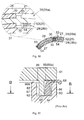
FIG. 11 andFIG. 12 show a related art.FIG. 11 is a sectional view that shows a conventional friction bonding structure.FIG. 12 is a sectional view taken along the line B-B inFIG. 11 . Alid 61 formed in a disc shape is attached to anopen end 60a of acylinder 60 formed in a generally cylindrical shape, and thelid 61 and thecylinder 60 are frictionally bonded together. Anannular groove 62 is formed at theopen end 60a of thecylinder 60. A slidingcontact projection 63 in an annular plate shape is formed on thelid 61. The slidingcontact projection 63 corresponds to theannular groove 62. Then, thecylinder 60 and thelid 61 are rotated relative to each other with the distal end of thesliding contact projection 63 in sliding contact with abottom 64 of theannular groove 62. In this way, a friction bondedportion 65 is formed at the sliding contact portions. - In addition,
wall portions annular groove 62 are arranged concentrically with the slidingcontact projection 63 that constitutes the friction bondedportion 65. Thus,annular storage portions 69 are formed between the slidingcontact projection 63 and thewall portions Burrs 68 produced at the friction bondedportion 65 are stored in thestorage portions 69. In this example, because most of the producedburrs 68 stick out from the friction bondedportion 65 radially outward, anouter storage portion 69a, which is one of thestorage portions 69, is set wider than the other one of thestorage portions 69. - However, in many cases, a narrow-width portion S is formed in the thus formed
storage portion 69 depending on the roundness of thesliding contact projection 63 and theannular groove 62 or the coaxiality between thesliding contact projection 63 and theannular groove 62. If theburrs 68 accumulate at the narrow-width portion S, theburrs 68 stick out of the storage portion 69 (69a). - In order to prevent the
burrs 68 from sticking out of the storage portion 69 (69a), for example, the size of the storage portion 69 (69a) may be increased or the meltage may be optimized to suppress production of theburrs 68. However, an increase in the size of thestorage portion 69 causes an increase in the size of a device. Also, in order to optimize the meltage resulting from friction bonding, it is necessary to carry out strict tolerance management for components of the device. This may cause cost increase. - The invention provides a friction bonding structure and a pump device with which the sticking-out of burrs is suppressed without the need for an increase in the size of a storage portion or strict tolerance management.
- According to a feature of an example of the invention, there is provided a plurality of partitioning elements that partition a storage portion in the circumferential direction to disperse burrs in the circumferential direction.
- The foregoing and further objects, features and advantages of the invention will become apparent from the following description of example embodiments with reference to the accompanying drawings, wherein like numerals are used to represent like elements and wherein:
-
FIG. 1 is a sectional view that shows the schematic configuration of an electric pump device according to a first embodiment of the invention; -
FIG. 2 is a perspective view of a portion of a motor case near an open end; -
FIG. 3 is a perspective view of a cover; -
FIG. 4 is a partial sectional view that shows a state where the cover is attached to the open end of the motor case; -
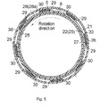
FIG. 5 is a sectional view taken along the line A-A inFIG. 1 ; -
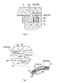
FIG. 6 is a partial sectional view that shows a friction bonding structure according to a second embodiment of the invention; -
FIG. 7 is a sectional view that shows a friction bonding structure according to a third embodiment of the invention; -
FIG. 8 is a sectional view that shows a friction bonding structure according to a fourth embodiment of the invention; -
FIG. 9 is a sectional view that shows a friction bonding structure according to a fifth embodiment of the invention; -
FIG. 10 is a sectional view that shows a friction bonding structure according to a sixth embodiment of the invention; -
FIG. 11 is a partial sectional view that schematically shows a conventional friction bonding structure and the sticking-out of burrs; and -
FIG. 12 is a sectional view taken along the line B-B inFIG. 11 . - Hereinafter, embodiments of the invention will be described with reference to the accompanying drawings.
- An electric pump device 1 according to a first embodiment of the invention will be described with reference to the accompanying drawings. As shown in
FIG. 1 , the electric pump device 1 includes a pump mechanism (gear pump) 3 and apump plate 4. Thepump mechanism 3 is accommodated in apump case 2. Thepump plate 4 is attached to one end (left-side end face 2a inFIG. 1 ) of thepump case 2, and constitutes a suction portion and discharge portion of thepump mechanism 3. In addition, amotor case 5 formed in a generally cylindrical shape is fixed to the other end (right-side end face 2b inFIG. 1 ) of thepump case 2, and accommodates amotor 6 that serves as a drive source and acontrol board 7 for themotor 6. Acover 8 formed in a generally disc shape is attached to anopen end 5a of themotor case 5. - The
motor case 5 is integrally formed with astator 10 of themotor 6 by resin molding. Thecontrol board 7 is accommodated in themotor case 5, at a position near theopen end 5a. In addition, a cylindrical support portion 11 is coaxially arranged inside thecylindrical motor case 5. The support portion 11 is formed to project from theend face 2b of thepump case 2. Arotor 12 of themotor 6 is fixed to amotor shaft 13 that is passed through the support portion 11. As a result, therotor 12 is arranged radially inward of thestator 10. - The
motor shaft 13 is rotatably supported by abearing 14 provided at the support portion 11. In addition, therotor 12 is formed in a closed-end cylindrical shape, and is arranged in thecylindrical motor case 5 so as to surround the radially outer side of the support portion 11. One end of themotor shaft 13 is fixed to abottom 12a of therotor 12. As a result, therotor 12 is coupled to aninner gear 3a of thepump mechanism 3 via themotor shaft 13. - As well as the
motor case 5, thecover 8 in the present embodiment is made of resin (e.g. polyamide). Thecover 8 is frictionally bonded to theopen end 5a of themotor case 5. In this way, the liquid-tightness of the inside of thecylindrical motor case 5 is ensured. - As shown in
FIG. 2 , anannular groove 21 is formed at theopen end 5a of themotor case 5. Theannular groove 21 is open in the axial direction (upward inFIG. 2 ). In addition, as shown inFIG. 3 , a slidingcontact projection 22 in an annular plate shape is formed on a mountingsurface 8a of thecover 8. The slidingcontact projection 22 corresponds to theannular groove 21. As shown inFIG. 4 , thecover 8 is attached to theopen end 5a of themotor case 5 by inserting the slidingcontact projection 22 of thecover 8 into theannular groove 21 and bringing the distal end of the slidingcontact projection 22 into contact with a bottom 23 of theannular groove 21. - In the present embodiment, the
cover 8 is rotated with the slidingcontact projection 22 in contact with the bottom 23 of theannular groove 21. At this time, themotor case 5 is fixed so as to be non-rotatable. Then, by rotating thecover 8 relative to themotor case 5, thecover 8 is frictionally bonded (spin-welded) to theopen end 5a of themotor case 5. - As shown in
FIG. 3 and FIG. 4 , amelting portion 24 is formed at the distal end of the slidingcontact projection 22. The meltingportion 24 is formed such that the width of themelting portion 24 is smaller than that of the other portion of the slidingcontact projection 22. The meltingportion 24 and the bottom 23 of theannular groove 21, which are melted by the frictional heat, are welded to each other. As a result, an annular friction bondedportion 25 is formed. -
Wall portions annular groove 21 are arranged so as to be coaxial with the friction bondedportion 25. In the present embodiment, clearances formed between thewall portions portion 25 are used asstorage portions 28, and products of melting, which stick out from the friction bondedportion 25, that is, "burrs", are stored in thestorage portions 28. - As shown in
FIG. 3 , a plurality ofprotrusions 29 is formed on the slidingcontact projection 22. Theprotrusions 29 protrude from the slidingcontact projection 22 radially outward. Specifically, eachprotrusion 29 is formed in a plate-shape, and extends in the axial direction. As shown inFIG. 5 , theprotrusions 29 are arranged in theannular groove 21 together with the slidingcontact projection 22 that will be the friction bondedportion 25. Astorage portion 28a, which is one of thestorage portions 28 and which is formed between the slidingcontact projection 22 and thewall portion 26 that surrounds the radially outer side of the slidingcontact projection 22, is partitioned in the circumferential direction by theprotrusions 29. - During friction bonding, burrs 30 produced at the friction bonded
portion 25 adhere to the correspondingprotrusions 29, located downstream of burr produced points in the rotation direction, as the sliding contact projection 22 (cover 8) rotates (in the counterclockwise direction in the example shown inFIG. 5 ). As a result, theburrs 30 adhere to theprotrusions 29, which may function as partitioning elements, and therefore theburrs 30 are stored in thestorage portion 28a while being dispersed in the circumferential direction. - According to the present embodiment, the following advantageous effects are obtained.
- With the above-described simple configuration, it is possible to avoid accumulation of the produced
burrs 30 at one location inside thestorage portion 28. As a result, it is possible to suppress the sticking-out of theburrs 30 to the outside of thestorage portion 28 without the need for an increase in the size of thestorage portion 28 or strict tolerance management for themotor case 5 and thecover 8. - The
motor case 5 and thecover 8 both are made of resin. Therefore, theburrs 30 produced through melting of resin tend to be light and bulky. Therefore, theburrs 30 tend to revolve inside thestorage portions 28 due to the rotation of thecover 8, and the sticking-out of theburrs 30 to the outside of thestorage portion 28a tends to occur due to the accumulation of theburrs 30. Therefore, by applying the configuration according to the present embodiment, it is possible to obtain remarkable advantageous effects. In addition, such friction bonding between resin members is widely adopted for cases of electronic devices because a melting temperature of resin is low. - The partitioning elements are formed of the
protrusions 29 formed on the slidingcontact projection 22. Therefore, theprotrusions 29, which may function as the partitioning elements, rotate together with the slidingcontact projection 22. That is, theprotrusions 29 are located next to the friction bondedportion 25, so the producedburrs 30 easily adhere to theprotrusions 29. As a result, it is possible to disperse theburrs 30 in thestorage portion 28a in the circumferential direction. - The
protrusions 29 are formed to protrude radially outward from the slidingcontact projection 22. Thus, theprotrusion 29, which may function as the partitioning elements, are arranged in thestorage portion 28a between the slidingcontact projection 22 and thewall portion 26 that surrounds the radially outer side of the slidingcontact projection 22. Usually, theburrs 30 produced at the friction bondedportion 25 mostly stick out from the friction bondedportion 25 radially outward by centrifugal force. Therefore, with the above configuration, it is possible to further effectively suppress the sticking-out of theburrs 30. - Next, an electric pump device according to a second embodiment of the invention will be described with reference to the accompanying drawings. Note that, for the sake of convenience, the same components as those in the first embodiment will be denoted by the same reference numerals as those in the first embodiment, and the description thereof is omitted.
- As shown in
FIG. 6 , in the present embodiment, aflange 35 is formed at adistal end 32a of awall portion 32, which is one ofwall portions annular groove 31 and which is located on the radially outer side (right side inFIG. 6 ) of thewall portion 33. Theannular groove 31 is formed at theopen end 5a of themotor case 5. Theflange 35 extends radially inward (toward the left side inFIG. 6 ), and is formed along the entire circumference of thewall portion 32. - The sticking-out of the
burrs 30 occurs when theburrs 30 are accumulated along awall face 32b of thewall portion 32 within thestorage portion 28a and climb over thewall portion 32. On the basis of this, in the present embodiment, theflange 35 that projects from thedistal end 32a of thewall portion 32 into thestorage portion 28a is formed to cover the upper side of thewall face 32b. In this way, theburrs 30 accumulated along thewall face 32b are retained within thestorage portion 28a by theflange 35. - According to the second embodiment described above, it is possible to efficiently store the produced
burrs 30 within thestorage portion 28a. Therefore, it is possible to reduce the volume of thestorage portion 28a by utilizing the high storage efficiency. Specifically, it is possible to make the depth of theannular groove 31 that forms thestorage portion 28a less than the depth of theannular groove 21 in the first embodiment (make the height of thewall portion 32 less than the height of thewall portion 26 in the first embodiment). As a result, it is possible to further reduce the size of the storage portion. - Note that the above-described embodiments may be modified as follows. In the above-described embodiments, the invention is applied to the electric pump device 1, more specifically, the friction bonding structure for frictionally bonding the
motor case 5 and thecover 8 together. However, the application of the invention is not limited to this. As long as two members are frictionally bonded together, the invention may be applied to any members. Therefore, the invention may be applied to, for example, a pump device that is driven through a pulley, or the like, or may be applied to a device other than a pump device. - In the above-described embodiments, the
protrusions 29 are formed on the slidingcontact projection 22, and the storage portion 28 (28a) are partitioned in the circumferential direction by theprotrusions 29 that may function as the partitioning elements. However, the invention is not limited to this configuration. For example, according to a third embodiment of the invention, as shown inFIG. 7 , a plurality ofprotrusions 44 that protrude radially inward is formed on awall portion 42, which is one ofwall portions annular groove 41 and which is located radially outward of thewall portion 43, and the storage portion 28 (28a) is partitioned in the circumferential direction by theprotrusions 44 that may function as partitioning elements. With this configuration as well as with the configurations in the first and second embodiments, theburrs 30 are stored in thestorage portion 28 while being dispersed in the circumferential direction. - Note that, the configuration in which the
protrusions 29 are formed on the slidingcontact projection 22 of thecover 8 as in the first and second embodiments has advantage over the configuration in the third embodiment, in that it is easy to form theprotrusions 29 and it is possible to arrange theprotrusions 29, which may function as the partitioning elements, at positions near the friction bondedportion 25 without contact between theprotrusions 29 and the friction bondedportion 25. - According to a fourth embodiment of the invention shown in
FIG. 8 , the distal ends ofprotrusions 47, which may function as partitioning elements, may be inclined in the direction of relative rotation between two members to be frictionally bonded together. Because theprotrusions 47 are formed on the slidingcontact projection 22 of thecover 8, the distal ends of theprotrusions 47 are inclined in the rotation direction (counterclockwise direction inFIG. 8 ) of thecover 8. With this configuration, it is possible to further reliably cause theburrs 30 to adhere to theprotrusions 47. - When protrusions, which may function as partitioning elements, are formed on (a wall portion of) the
motor case 5 that is in sliding contact with therotating cover 8 in a fixed state, the direction opposite to the rotation direction of thecover 8 is the "relative rotation direction". Therefore, for example, if the configuration in the third embodiment shown inFIG. 7 is employed as the base configuration, the distal ends of theprotrusions 44 need to be inclined in the clockwise direction. - In the first and second embodiments and the third and fourth embodiments shown in
FIG. 7 andFIG. 8 , the protrusions (29, 44 or 47), which may function as partitioning elements, are arranged in thestorage portion 28a located radially outward of the friction bondedportion 25. However, the invention is not limited to this configuration. When theburrs 30 tend to be produced on the radially inner side of the friction bondedportion 25, as according to a fifth embodiment of the invention shown inFIG. 9 , a plurality ofprotrusions 51 that protrude radially inward is formed over all around a slidingcontact projection 50. Thestorage portion 28b is partitioned in the circumferential direction by theprotrusions 51 that may function as partitioning elements. - According to a sixth embodiment of the invention, partitioning elements are arranged in both the
storage portions portion 25, respectively. As shown inFIG. 10 , a plurality ofprotrusions 53 and a plurality ofprotrusions 54 are formed radially outward and inward of a slidingcontact projection 52, respectively. Thestorage portion 28a and thestorage portion 28b located radially outward and inward of the friction bondedportion 25 are partitioned in the circumferential direction by theprotrusions 53 and theprotrusions 54, which may function as partitioning elements, respectively. Alternatively, a plurality of protrusions is formed on at least one of the wall portions of the annular groove so that at least one of partitioning elements arranged in the outer-side storage portion 28a and partitioning elements arranged in the inner-side storage portion 28b are formed of the protrusions formed on the at least one of the wall portions. - In the above-described embodiments, friction bonding is performed by bringing the
rotating cover 8 into sliding contact with theopen end 5a of themotor case 5 in a fixed state. However, the invention is not limited to this configuration. As long as two members to be frictionally bonded together are allowed to rotate relative to each other while being in sliding contact with each other, any two members may be used. - In the above-described embodiments, the
annular groove 21 is formed at theopen end 5a of themotor case 5, and thus themotor case 5 is used as a first member that has thewall portions contact projection 22 is formed on thecover 8 that may function as a second member. However, for example, when the cover is attached to the motor case from the lower side in the direction of gravitational force, an annular groove is formed in the cover and the wall portions of the annular groove are used as annular walls. Further, a sliding contact projection is formed on the motor case. In this case, the cover may function as a first member, and the motor case may function as a second member. - Furthermore, when an annular wall is provided and a burr storage portion is formed between the annular wall and a friction bonded portion, an annular groove need not be formed.
- In the above-described embodiments, the
motor case 5 and thecover 8 both are made of resin. However, the invention is not limited to this configuration. It is desirable that at least the sliding contact portions (the meltingportion 24 at the distal end of the slidingcontact projection 22 and the bottom 23 of the annular groove 21) should be made of resin. Note that resin other than polyamide may be used. Further, as long as friction bonding is allowed, both the motor case and the cover may be made of metal.
An annular groove (21) is formed at an open end of a motor case (5), and a sliding contact projection (22), which is in an annular plate-shape and corresponding to the annular groove (21), is formed on a cover (8). A bottom of the annular groove (21) and the sliding contact projection (22) rotate relative to each other while being in sliding contact with each other to form an annular friction bonded portion (25) therebetween. Wall portions (26, 27) of the annular groove (21) are arranged at such positions as to be concentric with the friction bonded portion (25). Thus, a storage portion (28) that stores burrs (30) produced at the friction bonded portion (25) is formed. A plurality of protrusions (29) that protrude radially outward is formed on the sliding contact projection (22) over all around. The storage portion (28, 28a) is partitioned in the circumferential direction by using the protrusions (29) as partitioning elements.
Claims (8)
- A friction bonding structure in which an annular friction bonded portion is formed between two members by rotating the two members relative to each other with the two members in contact with each other, and an annular wall is arranged at such a position as to be concentric with the friction bonded portion to form a storage portion between the annular wall and the friction bonded portion so that burrs are stored in the storage portion, characterized by comprising:a plurality of partitioning elements that partition the storage portion in a circumferential direction to disperse the burrs in the circumferential direction.
- The friction bonding structure according to claim 1, wherein at least sliding contact portions of the two members are made of resin.
- The friction bonding structure according to claim 1 or 2, wherein:the two members are a first member that has the annular wall and a second member that has an annular sliding contact projection that is in sliding contact with the first member and is arranged at such a position as to be concentric with the annular wall; andthe partitioning elements are a plurality of protrusions that are formed on at least one of the annular wall and the sliding contact projection and that protrude radially.
- The friction bonding structure according to claim 3, wherein distal ends of the protrusions are inclined in a direction of relative rotation between the two members.
- The friction bonding structure according to any one of claims 1 to 4, wherein:the two members are frictionally bonded together by rotating one of the two members with the other one of the two members fixed; andthe partitioning elements are formed on the one of the two members that is rotated.
- The friction bonding structure according to any one of claims 1 to 5, wherein a flange that extends into the storage portion is formed at a distal end of the annular wall.
- The friction bonding structure according to any one of claims 1 to 6, wherein the partitioning elements are arranged in the storage portion that is formed on radially outward of the friction bonded portion.
- A pump device, comprising the friction bonding structure according to any one of claims 1 to 7.
Applications Claiming Priority (1)
| Application Number | Priority Date | Filing Date | Title |
|---|---|---|---|
| JP2011198539A JP5915042B2 (en) | 2011-09-12 | 2011-09-12 | Friction joint structure and pump device |
Publications (1)
| Publication Number | Publication Date |
|---|---|
| EP2567772A2 true EP2567772A2 (en) | 2013-03-13 |
Family
ID=46762950
Family Applications (1)
| Application Number | Title | Priority Date | Filing Date |
|---|---|---|---|
| EP12182780A Withdrawn EP2567772A2 (en) | 2011-09-12 | 2012-09-03 | Friction bonding structure and pump device |
Country Status (4)
| Country | Link |
|---|---|
| US (1) | US20130064601A1 (en) |
| EP (1) | EP2567772A2 (en) |
| JP (1) | JP5915042B2 (en) |
| CN (1) | CN102990925A (en) |
Cited By (3)
| Publication number | Priority date | Publication date | Assignee | Title |
|---|---|---|---|---|
| WO2019072887A1 (en) * | 2017-10-12 | 2019-04-18 | Continental Automotive Gmbh | FUEL PUMP AND FUEL SUPPLY UNIT |
| WO2019072895A1 (en) * | 2017-10-12 | 2019-04-18 | Continental Automotive Gmbh | FUEL PUMP AND FUEL SUPPLY UNIT |
| FR3119652A1 (en) * | 2021-02-09 | 2022-08-12 | Tallano Technologie | Device allowing blind relative positioning of internal components. |
Families Citing this family (8)
| Publication number | Priority date | Publication date | Assignee | Title |
|---|---|---|---|---|
| US9810223B2 (en) * | 2012-09-20 | 2017-11-07 | Asmo Co., Ltd. | Electric pump |
| US10105898B2 (en) | 2015-03-20 | 2018-10-23 | Toyota Jidosha Kabushiki Kaisha | Resin joined body, manufacturing method of resin joined body, and vehicle structure |
| JP6341156B2 (en) * | 2015-03-20 | 2018-06-13 | トヨタ自動車株式会社 | Resin bonded body, resin bonded body manufacturing method, and vehicle structure |
| CN105108326A (en) * | 2015-09-18 | 2015-12-02 | 张家港市和伟五金工具厂 | Friction-stir hardware welding method |
| CN105108327A (en) * | 2015-09-18 | 2015-12-02 | 张家港市和伟五金工具厂 | Hardware welding method based on friction stir equipment |
| CN105127586A (en) * | 2015-09-18 | 2015-12-09 | 张家港市和伟五金工具厂 | Hardware tool welding method adopting stirring friction technology |
| US11383519B2 (en) | 2019-03-27 | 2022-07-12 | Canon Kabushiki Kaisha | Liquid storage bottle and method of manufacturing the same |
| CN112296507B (en) * | 2020-10-30 | 2022-03-25 | 辽宁忠旺铝合金精深加工有限公司 | Friction stir welding method for aluminum alloy water-cooled motor shell |
Citations (1)
| Publication number | Priority date | Publication date | Assignee | Title |
|---|---|---|---|---|
| JP2005081351A (en) | 2003-09-04 | 2005-03-31 | Aisin Aw Co Ltd | Friction pressure welding member and differential gear equipped with member |
Family Cites Families (7)
| Publication number | Priority date | Publication date | Assignee | Title |
|---|---|---|---|---|
| JPS57125012A (en) * | 1981-01-28 | 1982-08-04 | Asahi Chem Ind Co Ltd | Rotary frictional welding method |
| US4832769A (en) * | 1987-05-19 | 1989-05-23 | A. R. D. Industries Ltd. | Friction welding flash trap seal and method of producing same |
| DE4341954C2 (en) * | 1993-12-09 | 1996-05-15 | Daimler Benz Ag | Method and device for the positive locking of parts during friction welding |
| JP2002283455A (en) * | 2001-03-26 | 2002-10-03 | Kyosan Denki Co Ltd | Connecting structure of resin component |
| JP4044021B2 (en) * | 2003-09-09 | 2008-02-06 | アスモ株式会社 | Manufacturing method of resin parts |
| DE102006053800B4 (en) * | 2006-11-15 | 2025-08-14 | Ejot Gmbh & Co. Kg | Friction welding of two superimposed flat components |
| US7726542B2 (en) * | 2008-06-25 | 2010-06-01 | Gm Global Technology Operations, Inc. | Friction-welded assembly with interlocking feature and method for forming the assembly |
-
2011
- 2011-09-12 JP JP2011198539A patent/JP5915042B2/en not_active Expired - Fee Related
-
2012
- 2012-08-13 CN CN2012102872138A patent/CN102990925A/en active Pending
- 2012-09-03 EP EP12182780A patent/EP2567772A2/en not_active Withdrawn
- 2012-09-04 US US13/602,849 patent/US20130064601A1/en not_active Abandoned
Patent Citations (1)
| Publication number | Priority date | Publication date | Assignee | Title |
|---|---|---|---|---|
| JP2005081351A (en) | 2003-09-04 | 2005-03-31 | Aisin Aw Co Ltd | Friction pressure welding member and differential gear equipped with member |
Cited By (4)
| Publication number | Priority date | Publication date | Assignee | Title |
|---|---|---|---|---|
| WO2019072887A1 (en) * | 2017-10-12 | 2019-04-18 | Continental Automotive Gmbh | FUEL PUMP AND FUEL SUPPLY UNIT |
| WO2019072895A1 (en) * | 2017-10-12 | 2019-04-18 | Continental Automotive Gmbh | FUEL PUMP AND FUEL SUPPLY UNIT |
| FR3119652A1 (en) * | 2021-02-09 | 2022-08-12 | Tallano Technologie | Device allowing blind relative positioning of internal components. |
| WO2022171648A1 (en) * | 2021-02-09 | 2022-08-18 | Tallano Technologie | Device allowing blind relative positioning of internal components |
Also Published As
| Publication number | Publication date |
|---|---|
| CN102990925A (en) | 2013-03-27 |
| US20130064601A1 (en) | 2013-03-14 |
| JP2013059883A (en) | 2013-04-04 |
| JP5915042B2 (en) | 2016-05-11 |
Similar Documents
| Publication | Publication Date | Title |
|---|---|---|
| US20130064601A1 (en) | Friction bonding structure and pump device | |
| JP7022051B2 (en) | Lubrication / cooling structure of electric drive unit | |
| JP5545582B2 (en) | Spindle motor and hard disk drive including the same | |
| JP2014059009A (en) | Bearing device, spindle motor, and disc driving device | |
| EP3220519B1 (en) | Motor with deceleration mechanism | |
| EP3540922A1 (en) | Drive device | |
| CN115549344A (en) | Drive device and vehicle | |
| JP6221030B2 (en) | Bearing mechanism and blower fan | |
| JP6221035B2 (en) | Bearing mechanism, motor and blower fan | |
| US20160056675A1 (en) | Brushless motor and disk drive apparatus | |
| JPWO2018159477A1 (en) | Pump device | |
| KR20130088355A (en) | Spindle motor | |
| KR20140035651A (en) | Spindle motor and hard disk drive including the same | |
| US20120169165A1 (en) | Spindle motor | |
| JP2007263228A (en) | Dynamic pressure bearing device | |
| JP2013185706A (en) | Fluid dynamic pressure bearing assembly and motor including the same | |
| WO2018037596A1 (en) | Electric fluid pump | |
| US20130266463A1 (en) | Fan motor | |
| JP5621406B2 (en) | Electric motor and rotor | |
| JP2017223319A (en) | Seal member and motor | |
| JP2015031172A (en) | Electric pump | |
| KR20160081056A (en) | Spindle motor and driving device of recording disk having the same | |
| JP2020188543A (en) | Motor and axial fan | |
| JP2006200742A (en) | Spindle motor equipped with fluid dynamic-pressure bearing system | |
| JP2006170431A (en) | Fluid dynamic pressure bearing device and spindle motor mounted therewith as well as recording disc drive mechanism |
Legal Events
| Date | Code | Title | Description |
|---|---|---|---|
| PUAI | Public reference made under article 153(3) epc to a published international application that has entered the european phase |
Free format text: ORIGINAL CODE: 0009012 |
|
| AK | Designated contracting states |
Kind code of ref document: A2 Designated state(s): AL AT BE BG CH CY CZ DE DK EE ES FI FR GB GR HR HU IE IS IT LI LT LU LV MC MK MT NL NO PL PT RO RS SE SI SK SM TR |
|
| AX | Request for extension of the european patent |
Extension state: BA ME |
|
| STAA | Information on the status of an ep patent application or granted ep patent |
Free format text: STATUS: THE APPLICATION HAS BEEN WITHDRAWN |
|
| 18W | Application withdrawn |
Effective date: 20150323 |