EP2566296A1 - Induction cooker with time-sharing control function and method of operating the same - Google Patents
Induction cooker with time-sharing control function and method of operating the same Download PDFInfo
- Publication number
- EP2566296A1 EP2566296A1 EP12183008A EP12183008A EP2566296A1 EP 2566296 A1 EP2566296 A1 EP 2566296A1 EP 12183008 A EP12183008 A EP 12183008A EP 12183008 A EP12183008 A EP 12183008A EP 2566296 A1 EP2566296 A1 EP 2566296A1
- Authority
- EP
- European Patent Office
- Prior art keywords
- unit
- cooker
- switch
- units
- control
- Prior art date
- Legal status (The legal status is an assumption and is not a legal conclusion. Google has not performed a legal analysis and makes no representation as to the accuracy of the status listed.)
- Granted
Links
- 230000006698 induction Effects 0.000 title claims abstract description 84
- 238000000034 method Methods 0.000 title claims abstract description 16
- 230000000295 complement effect Effects 0.000 claims description 40
- XUIMIQQOPSSXEZ-UHFFFAOYSA-N Silicon Chemical compound [Si] XUIMIQQOPSSXEZ-UHFFFAOYSA-N 0.000 claims description 3
- 230000002457 bidirectional effect Effects 0.000 claims description 3
- 229910052710 silicon Inorganic materials 0.000 claims description 3
- 239000010703 silicon Substances 0.000 claims description 3
- 238000010586 diagram Methods 0.000 description 33
- 230000003071 parasitic effect Effects 0.000 description 5
- 208000032365 Electromagnetic interference Diseases 0.000 description 2
- 238000010411 cooking Methods 0.000 description 2
- 230000005669 field effect Effects 0.000 description 2
- 238000010438 heat treatment Methods 0.000 description 2
- 238000002955 isolation Methods 0.000 description 2
- 239000004065 semiconductor Substances 0.000 description 2
- RYGMFSIKBFXOCR-UHFFFAOYSA-N Copper Chemical compound [Cu] RYGMFSIKBFXOCR-UHFFFAOYSA-N 0.000 description 1
- 238000006243 chemical reaction Methods 0.000 description 1
- 230000002452 interceptive effect Effects 0.000 description 1
- 239000002184 metal Substances 0.000 description 1
- 229910052751 metal Inorganic materials 0.000 description 1
- 239000000779 smoke Substances 0.000 description 1
Images


Classifications
-
- H—ELECTRICITY
- H05—ELECTRIC TECHNIQUES NOT OTHERWISE PROVIDED FOR
- H05B—ELECTRIC HEATING; ELECTRIC LIGHT SOURCES NOT OTHERWISE PROVIDED FOR; CIRCUIT ARRANGEMENTS FOR ELECTRIC LIGHT SOURCES, IN GENERAL
- H05B6/00—Heating by electric, magnetic or electromagnetic fields
- H05B6/02—Induction heating
- H05B6/06—Control, e.g. of temperature, of power
- H05B6/062—Control, e.g. of temperature, of power for cooking plates or the like
- H05B6/065—Control, e.g. of temperature, of power for cooking plates or the like using coordinated control of multiple induction coils
Definitions
- the present disclosure relates generally to an induction cooker and a method of operating the same, and more particularly to an induction cooker with a time-sharing control function and a method of operating the same.
- An induction cooker which is composed of power electronic circuits, uses induction heating to directly heat a cooking vessel.
- a coil of copper wire is placed underneath the cooking pot.
- An alternating electric current flows through the coil, which produces an oscillating magnetic field. This field induces an electric current in the pot.
- Current flowing in the metal pot produces resistive heating which heats the food. While the current is large, it is produced by a low voltage. Because the induction cooker has the advantages such as high thermal efficiency, easy to use, no smoke and gas pollution, safety and health, and so on, it is very suitable for use in the modem family.
- an induction cooker with a time-sharing control function and a method of operating the same to implement the induction cooker with the time-sharing control function by controlling duty cycle ratios, thus simplifying control circuits and reducing the amount of switch elements and consumption energy thereof.
- the induction cooker includes a plurality of switch units, a control unit, and a plurality of cooker units.
- the control unit is electrically connected to the switch units and configured to control each of the switch units.
- Each of the cooker units is electrically connected to two corresponding switch units.
- the control unit is configured to switch on the switch units correspondingly connected to one or more cooker units of a first subgroup of cooker units selected from the plurality of cooker units so as to control the one or more cooker units of the first subgroup in a working condition and to keep high-level on the switch units correspondingly connected to one or more cooker units of a second subgroup of cooker units selected from the plurality of cooker units so as to control the one or more cooker units of the second subgroup in a non-working condition, thus alternately operating in time-sharing control manner to the induction cooker, wherein the first subgroup is different from the second subgroup.
- the cooker units are hereinafter classified into two logical subgroups based on the respective working status.
- the cooker units in a working condition fall into the so-called first subgroup, while the cooker units in a non-working condition fall into the so-called second subgroup.
- Each of these subgroups may consist of one or more of the cooker units and preferably the two subgroups do not overlap, i.e. the cooker units are either members of the first subgroup or second subgroup.
- This classification may be time-varying, depending on the operation conditions.
- Another object of the invention is to provide a method of an induction cooker with a time-sharing control function to solve the above-mentioned problems. Accordingly, the method includes the following steps: (a) a plurality of switch units are provided; (b) a plurality of cooker units are provided; (c) a control unit is provided; and (d) the control unit switches on the switch units correspondingly connected to one or more cooker units of a first subgroup of cooker units selected from the plurality of cooker units so as to control the one or more cooker units of the first subgroup in a working condition and keeping high-level on the switch units correspondingly connected to one or more cooker units of a second subgroup of cooker units selected from the plurality of cooker units so as to control the one or more cooker units of the second subgroup in a non-working condition, wherein the first subgroup is different from the second subgroup.
- the present invention discloses an induction cooker with a time-sharing control function which is supplied by an AC power.
- the induction cooker includes a plurality of switch units, a control unit, and a plurality of cooker units.
- the control unit is electrically connected to the switch units to control turning on or turning off each of the switch units.
- Each of the cooker units is electrically connected to two adjacent corresponding switch units.
- control unit switches on the switch units adjacently and correspondingly connected to one or more cooker units of a first subgroup of cooker units selected from the plurality of cooker units so as to control the one or more cooker units of the first subgroup in a working condition (namely, under switching on control) and keeps high-level on the switch units adjacently and correspondingly connected to one or more cooker units of a second subgroup of cooker units selected from the plurality of cooker units so as to control the one or more cooker units of the second subgroup in a non-working condition, thus alternately operating in time-sharing control manner to the induction cooker.
- the first subgroup is different from the second subgroup.
- Fig. 1A is a schematic circuit diagram of an induction cooker with a time-sharing control function according to a first embodiment of the present disclosure.
- the induction cooker includes two cooker units L11, L12 (namely, a first cooker unit L11 and a second cooker unit L12), four switch units S11 ⁇ S14 (namely, a first switch unit S11, a second switch unit S12, a third switch unit S 13, and a fourth switch unit S 14), and a control unit Uc1.
- each of the switch units is a power transistor switch, such as a metal-oxide-semiconductor field-effect transistor (MOSFET), a bipolar junction transistor (BJT), or an insulated gate bipolar transistor (IGBT), but not limited.
- MOSFET metal-oxide-semiconductor field-effect transistor
- BJT bipolar junction transistor
- IGBT insulated gate bipolar transistor
- the control unit Uc1 switches on two switch units adjacently and correspondingly connected to a cooker unit in a working condition and keeps high-level on other switch units adjacently and correspondingly connected to a cooker unit in a non-working condition, thus alternately operating in time-sharing control manner to the first cooker unit L11 and the second cooker unit L12.
- Fig. 1B is a timing diagram of the time-sharing control of the induction cooker according to the first embodiment of the present disclosure.
- the control unit Uc1 produces a first control signal S11', a second control signal S 12', a third control signal S 13', and a fourth control signal S 14' to control turning on or turning off the first switch unit S 11, the second switch unit S12, the third switch unit S 13, and the fourth switch unit S 14, respectively.
- the control unit Uc1 can provide complementary control signals to the first switch unit S11 and the second switch unit S 12 at a first time t11 to control the output power of the first cooker unit L11.
- the complementary control signals mean that the first control signal S11' is in high-level and the second control signal S12' is in low-level, or vice versa. At this time, the second cooker unit L12 does not output power.
- the third control signal S 13' and the fourth control signal S 14' are both low-level so as to turn off the third switch unit S13 and the fourth switch unit S14.
- the control unit Uc1 provides complementary control signals to control the third switch unit S 13 and the fourth switch unit S 14.
- the complementary control signals mean that the third control signal S13' is in high-level and the fourth control signal S14' is in low-level, or vice versa. At this time, the second cooker unit L12 does output power.
- the first control signal S11' and the second control signal S12' are both low-level so as to turn off the first switch unit S11 and the second switch unit S12.
- a duty cycle ratio between controlling the first cooker unit L11 and the second cooker unit L12 is 2:1 so that the output power of the first cooker unit L11 and that of the second cooker unit L12 are 800 watts and 400 watts, respectively.
- Fig. 2A is a schematic circuit diagram of the induction cooker with a time-sharing control function according to a second embodiment of the present disclosure.
- the induction cooker includes four cooker units L21 ⁇ L24 (namely, a first cooker unit L21, a second cooker unit L22, a third cooker unit L23, and a fourth cooker unit L24), six switch units S21 ⁇ S26 (namely, a first switch unit S21, a second switch unit S22, a third switch unit S23, a fourth switch unit S24, a fifth switch unit S25, and a sixth switch unit S26), and a control unit Uc2.
- the first switch unit S21 is electrically connected to the second switch unit S22 and then electrically connected to the first cooker unit L21.
- the second switch unit S22 is electrically connected to the third switch unit S23 and then electrically connected to the second cooker unit L22.
- the fourth switch unit S24 is electrically connected to the fifth switch unit S25 and then electrically connected to the third cooker unit L23.
- the fifth switch unit S25 is electrically connected to the sixth switch unit S26 and then electrically connected to the fourth cooker unit L24.
- the control unit Uc2 switches on two switch units adjacently and correspondingly connected to a cooker unit in a working condition and keeps high-level on other switch units adjacently and correspondingly connected to a cooker unit in a non-working condition, thus alternately operating in time-sharing control manner to the first cooker unit L21 and the second cooker unit L22 and also to the third cooker unit L23 and the fourth cooker unit L24.
- the detail description of the time-sharing control is referenced to Fig. 2B which is a timing diagram of the time-sharing control of the induction cooker according to the second embodiment of the present disclosure.
- the control unit Uc2 produces a first control signal S21', a second control signal S22', a third control signal S23', a fourth control signal S24', a fifth control signal S25', and a sixth control signal S26' to control turning on or turning off the first switch unit S21, the second switch unit S22, the third switch unit S23, the fourth switch unit S24, the fifth switch unit S25, and the sixth switch unit S26, respectively.
- the first cooker unit L21 and the second cooker unit L22 output 800 watts and 400 watts, respectively.
- the third cooker unit L23 and the fourth cooker unit L24 output 800 watts and 400 watts, respectively.
- the output power of the first cooker unit L21 is controlled earlier than that of the second cooker unit L22 is controlled in the time-sharing control during a duty cycle, but not limited.
- the output power of the third cooker unit L23 is controlled earlier than that of the fourth cooker unit L24 is controlled in the time-sharing control during a duty cycle, but not limited.
- control unit Uc2 can control either the first cooker unit L21 or the second cooker unit L22 and simultaneously control either the third cooker unit L23 or the fourth cooker unit L24. Accordingly, the control unit Uc2 can provide complementary control signals to the first switch unit S21 and the second switch unit S22 at a first time t21 and further turn on the third switch unit S23 to control the output power of the first cooker unit L21.
- the complementary control signals mean that the first control signal S21' is in high-level and the second control signal S22' is in low-level, or vice versa, and further the third control signal S23' is kept in high-level. At this time, the second cooker unit L22 does not output power.
- the control unit Uc2 can also provide complementary control signals to the fourth switch unit S24 and the fifth switch unit S25 and further turn on the sixth switch unit S26 to control the output power of the third cooker unit L23.
- the complementary control signals mean that the fourth control signal S24' is in high-level and the fifth control signal S25' is in low-level, or vice versa, and further the sixth control signal S26' is kept in high-level.
- the fourth cooker unit L24 does not output power.
- the control unit Uc2 provides complementary control signals to control the second switch unit S22 and the third switch unit S23 and further turns on the first switch unit S21.
- the complementary control signals mean that the second control signal S22' is in high-level and the third control signal S23' is in low-level, or vice versa, and further the first control signal S21' is kept in high-level.
- the second cooker unit L22 does output power.
- control unit Uc2 can also provide complementary control signals to the fourth switch unit S24 and the fifth switch unit S25 and further still turn on the sixth switch unit S26 to control that the third cooker unit L23 keeps outputting power. Until a third time t23, the fourth cooker unit L24 is in turn to output power but the third cooker unit L23 does not output power and further the second cooker unit L22 also keeps outputting power. Hence, the control unit Uc2 provides complementary control signals to control the fifth switch unit S25 and the sixth switch unit S26 and further turns on the fourth switch unit S24 to control the output power of the fourth cooker unit L24.
- the complementary control signals mean that the fifth control signal S25' is in high-level and the sixth control signal S26' is in low-level, or vice versa, and further the fourth control signal S24' is kept in high-level.
- the fourth cooker unit L24 does output power.
- the control unit Uc2 can also provide complementary control signals to the second switch unit S22 and the third switch unit S23 and further still turn on the first switch unit S21 to control that the second cooker unit L22 keeps outputting power.
- the induction cooker provides the time-sharing control in a complete duty cycle.
- a duty cycle ratio between controlling the first cooker unit L21 and the second cooker unit L22 is 1:2 so that the output power of the first cooker unit L21 and that of the second cooker unit L22 are 400 watts and 800 watts, respectively.
- a duty cycle ratio between controlling the third cooker unit L23 and the fourth cooker unit L24 is 2:1 so that the output power of the third cooker unit L23 and that of the fourth cooker unit L24 are 800 watts and 400 watts, respectively.
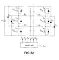
- Fig. 3A is a schematic circuit diagram of the induction cooker with a time-sharing control function according to a third embodiment of the present disclosure.
- the circuit structure of the third embodiment is substantially identical to that of the above-mentioned second embodiment.
- the third embodiment further includes a plurality of diode units D31 ⁇ D34, namely, a first diode unit D31, a second diode unit D32, a third diode unit D33, and a fourth diode unit D34.
- the first diode unit D31 is electrically connected to a first switch unit S31 and a common contact of a second switch unit S32 and a third switch unit S33.
- the second diode unit D32 is electrically connected to the third switch unit S33 and a common contact of the first switch unit S31 and the second switch unit S32.
- the third diode unit D33 is electrically connected to a fourth switch unit S34 and a common contact of a fifth switch unit S35 and a sixth switch unit S36.
- the fourth diode unit D34 is electrically connected to the sixth switch unit S36 and a common contact of the fourth switch unit S34 and the fifth switch unit S35.
- the time-sharing control in this embodiment is identical to that in the second embodiment and reference is made to Fig. 3B which is a timing diagram of the time-sharing control of the induction cooker according to the third embodiment of the present disclosure.
- the switch units S31 ⁇ S36 are controlled by the control signals S31' ⁇ S36' produced from a control unit Uc3, respectively.
- each of the switch units S31 ⁇ S36 is connected in parallel to an anti-parallel diode (not labeled) and a parasitic capacitance (not shown). Due to inherent parasitic effects of the components, the switch units S31 ⁇ S36 would accumulate parasitic losses and increase electromagnetic interferences when the switch units S31 ⁇ S36 are under zero-voltage-switching operations. Accordingly, the diode units D31 ⁇ D34 play roles as freewheeling diodes in this embodiment to provide freewheeling paths when the switch units S31 ⁇ S36 are under zero-voltage-switching operations, thus improving inherent parasitic effects of the components in the second embodiment.
- Fig. 4A is a schematic circuit diagram of the induction cooker with a time-sharing control function according to a fourth embodiment of the present disclosure.
- the induction cooker includes three cooker units L41 ⁇ L43 (namely, a first cooker unit L41, a second cooker unit L42, and a third cooker unit L43), five switch units S41 ⁇ S45 (namely, a first switch unit S41, a second switch unit S42, a third switch unit S43, a fourth switch unit S44, and a fifth switch unit S45), and a control unit Uc4.
- the first switch unit S41 is electrically connected to the second switch unit S42 and then electrically connected to the first cooker unit L41.
- the second switch unit S42 is electrically connected to the third switch unit S43 and then electrically connected to the second cooker unit L42.
- the fourth switch unit S44 is electrically connected to the fifth switch unit S45 and then electrically connected to the third cooker unit L43.
- the control unit Uc4 switches on two switch units adjacently and correspondingly connected to a cooker unit in a working condition and keeps high-level on other switch units adjacently and correspondingly connected to a cooker unit in a non-working condition, thus alternately operating in time-sharing control manner to the first cooker unit L41 and the second cooker unit L42 and also to the third cooker unit L43.
- the detail description of the time-sharing control is referenced to Fig. 4B which is a timing diagram of the time-sharing control of the induction cooker according to the fourth embodiment of the present disclosure.
- the control unit Uc4 produces a first control signal S41', a second control signal S42', a third control signal S43', a fourth control signal S44', and a fifth control signal S45' to control turning on or turning off the first switch unit S41, the second switch unit S42, the third switch unit S43, the fourth switch unit S44, and the fifth switch unit S45, respectively.
- the control unit Uc4 can control either the first cooker unit L41 or the second cooker unit L42 and simultaneously control the third cooker unit L43.
- control unit Uc4 can provide complementary control signals to the first switch unit S41 and the second switch unit S42 at a first time t41 and further turn on the third switch unit S43 to control the output power of the first cooker unit L41.
- the complementary control signals mean that the first control signal S41' is in high-level and the second control signal S42' is in low-level, or vice versa, and further the third control signal S43' is kept in high-level.
- the second cooker unit L42 does not output power.
- the control unit Uc4 can also provide complementary control signals to the fourth switch unit S44 and the fifth switch unit S45 to control the output power of the third cooker unit L43.
- the complementary control signals mean that the fourth control signal S44' is in high-level and the fifth control signal S45' is in low-level, or vice versa. Until a second time t42, the third cooker unit L43 does not output power and the first cooker unit L41 also keeps outputting power. Hence, the fourth control signal S44' and the fifth control signal S45' are both controlled in low-level by the control unit Uc4 to turn off the fourth switch unit S44 and the fifth switch unit S45 so that the third cooker unit L43 does not output power. In addition, the control unit Uc4 still provides complementary control signals to the first switch unit S41 and the second switch unit S42 and further turns on the third switch unit S43 to control that the first cooker unit L41 keeps outputting power.
- the control unit Uc4 provides complementary control signals to control the second switch unit S42 and the third switch unit S43 and further turns on the first switch unit S41 to control the output power of the second cooker unit L42.
- the complementary control signals mean that the second control signal S42' is in high-level and the third control signal S43' is in low-level, or vice versa, and further the first control signal S41' is kept in high-level.
- the fourth control signal S44' and the fifth control signal S45' are still both controlled in low-level by the control unit Uc4 to turn off the fourth switch unit S44 and the fifth switch unit S45 so that the third cooker unit L43 still does not output power.
- the induction cooker provides the time-sharing control in a complete duty cycle. Accordingly, a duty cycle ratio between controlling the first cooker unit L41 and the second cooker unit L42 is 2:1 so that the output power of the first cooker unit L41 and that of the second cooker unit L42 are 800 watts and 400 watts, respectively. Also, a duty cycle of controlling the third cooker unit L43 is 50% so that the output power of the third cooker unit L43 is 600 watts.
- Fig. 5A is a schematic circuit diagram of the induction cooker with a time-sharing control function according to a fifth embodiment of the present disclosure.
- the induction cooker includes three cooker units L51 ⁇ L53 (namely, a first cooker unit L51, a second cooker unit L52, and a third cooker unit L53), four switch units S51 ⁇ S54 (namely, a first switch unit S51, a second switch unit S52, a third switch unit S53, and a fourth switch unit S54), and a control unit Uc5.
- the first switch unit S51 is electrically connected to the second switch unit S52 and then electrically connected to the first cooker unit L51.
- the second switch unit S52 is electrically connected to the third switch unit S53 and then electrically connected to the second cooker unit L52.
- the third switch unit S53 is electrically connected to the fourth switch unit S54 and then electrically connected to the third cooker unit L53.
- the control unit Uc5 switches on two switch units adjacently and correspondingly connected to a cooker unit in a working condition and keeps high-level on other switch units adjacently and correspondingly connected to a cooker unit in a non-working condition, thus alternately operating in time-sharing control manner to the first cooker unit L51, the second cooker unit L52, and the third cooker unit L53.
- the detail description of the time-sharing control is referenced to Fig. 5B which is a timing diagram of the time-sharing control of the induction cooker according to the fifth embodiment of the present disclosure.
- the control unit Uc5 produces a first control signal S51', a second control signal S52', a third control signal S53', and a fourth control signal S54' to control turning on or turning off the first switch unit S51, the second switch unit S52, the third switch unit S53, and the fourth switch unit S54, respectively.
- the first cooker unit L51, the second cooker unit L52, and the third cooker unit L53 output 600 watts, 400 watts, and 200 watts, respectively. Also, the output power of the first cooker unit L51 is controlled earlier than that of the second cooker unit L52 is controlled and then that of the third cooker unit L53 is controlled in the time-sharing control during a duty cycle, but not limited. In this case, the control unit Uc5 can control either the first cooker unit L51, the second cooker unit L52, or the third cooker unit L53.
- control unit Uc5 can provide complementary control signals to the first switch unit S51 and the second switch unit S52 at a first time t51 and further turn on the third switch unit S53 and the fourth switch unit S54 to control the output power of the first cooker unit L51.
- the complementary control signals mean that the first control signal S51' is in high-level and the second control signal S52' is in low-level, or vice versa, and further the third control signal S53' and the fourth control signal S54' are kept in high-level.
- the second cooker unit L52 and the third cooker unit L53 do not output power.
- the second cooker unit L52 is in turn to output power but the first cooker unit L51 and the third cooker unit L53 do not output power.
- the control unit Uc5 provides complementary control signals to control the second switch unit S52 and the third switch unit S53 and further turns on the first switch unit S51 and the fourth switch unit S54 to control the output power of the second cooker unit L52.
- the complementary control signals mean that the second control signal S52' is in high-level and the third control signal S53' is in low-level, or vice versa, and further the first control signal S51' and the fourth control signal S54' are kept in high-level.
- the first cooker unit L51 and the third cooker unit L53 do not output power.
- the third cooker unit L53 is in turn to output power but the first cooker unit L51 and the second cooker unit L52 do not output power.
- the control unit Uc5 provides complementary control signals to control the third switch unit S53 and the fourth switch unit S54 and further turns on the first switch unit S51 and the second switch unit S52 to control the output power of the third cooker unit L53.
- the complementary control signals mean that the third control signal S53' is in high-level and the fourth control signal S54' is in low-level, or vice versa, and further the first control signal S51' and the second control signal S52' are kept in high-level.
- the first cooker unit L51 and the second cooker unit L52 do not output power.
- the induction cooker provides the time-sharing control in a complete duty cycle.
- a duty cycle ratio between controlling the first cooker unit L51, the second cooker unit L52, and the third cooker unit L53 is 3:2:1 so that the output power of the first cooker unit L51, the second cooker unit L52, and the third cooker unit L53 are 600 watts, 400 watts, and 200 watts, respectively.
- Fig. 6A is a schematic circuit diagram of the induction cooker with a time-sharing control function according to a sixth embodiment of the present disclosure.
- the induction cooker includes four cooker units L61 ⁇ L64 (namely, a first cooker unit L61, a second cooker unit L62, a third cooker unit L63, and a fourth cooker unit L64), two switch units S61,S62 (namely, a first switch unit S61 and a second switch unit S62), four auxiliary switch units G61 ⁇ G64 (namely, a first auxiliary switch unit G61, a second auxiliary switch unit G62, a third auxiliary switch unit G63, and a fourth auxiliary switch unit G64), and a control unit Uc6.
- four cooker units L61 ⁇ L64 namely, a first cooker unit L61, a second cooker unit L62, a third cooker unit L63, and a fourth cooker unit L64
- two switch units S61,S62 namely, a first switch unit S61 and a second switch unit S62
- each of the auxiliary switch units is a bidirectional triode thyristor (also called a triode for alternating current, TRIAC) or a silicon controlled rectifier (SCR), but not limited.
- the first auxiliary switch unit G61 is electrically connected to the first cooker unit L61.
- the second auxiliary switch unit G62 is electrically connected to the second cooker unit L62.
- the third auxiliary switch unit G63 is electrically connected to the third cooker unit L63.
- the fourth auxiliary switch unit G64 is electrically connected to the fourth cooker unit L64.
- the first switch unit S61 is electrically connected to the second switch unit S62 and then electrically connected to the in-series auxiliary switch units G61 ⁇ G64 and cooker units L61 ⁇ L64.
- the control unit Uc6 switches on two switch units adjacently and correspondingly connected to a cooker unit in a working condition and keeps high-level on other switch units adjacently and correspondingly connected to a cooker unit in a non-working condition, thus alternately operating in time-sharing control manner to the first cooker unit L61, the second cooker unit L62, the third cooker unit L63, and the fourth cooker unit L64.
- the detail description of the time-sharing control is referenced to Fig. 6B which is a timing diagram of the time-sharing control of the induction cooker according to the sixth embodiment of the present disclosure.
- the control unit Uc6 produces a first control signal S61' and a second control signal S62' to control turning on or turning off the first switch unit S61 and the second switch unit S62, respectively.
- control unit Uc6 produces a first auxiliary control signal G61', a second auxiliary control signal G62', a third auxiliary control signal G63', and a fourth auxiliary control signal G64' to control turning on or turning off the first auxiliary switch unit G61, the second auxiliary switch unit G62, the third auxiliary switch unit G63, and the fourth auxiliary switch unit G64, respectively.
- the first cooker unit L61, the second cooker unit L62, the third cooker unit L63, and the fourth cooker unit L64 output 400 watts, 400 watts, 200 watts, and 200 watts, respectively.
- the output power of the first cooker unit L61 is controlled earlier than that of the second cooker unit L62 is controlled and then that of the third cooker unit L63 and is controlled and then that of the fourth cooker unit L64 is controlled in the time-sharing control during a duty cycle, but not limited.
- the control unit Uc6 can control either the first cooker unit L61, the second cooker unit L62, the third cooker unit L63, or the fourth cooker unit L64.
- control unit Uc6 can provide complementary control signals to the first switch unit S61 and the second switch unit S62 at a first time t61 and further turn on the first auxiliary switch unit G61 to control the output power of the first cooker unit L61.
- the complementary control signals mean that the first control signal S61' is in high-level and the second control signal S62' is in low-level, or vice versa, and further the first auxiliary control signal G61' is kept in turned-on-level and the other auxiliary control signals G62' ⁇ G64' are kept in turned-off-level.
- the second cooker unit L62, the third cooker unit L63, and the fourth cooker unit L64 do not output power.
- the control unit Uc6 provides complementary control signals to control the first switch unit S61 and the second switch unit S62 and further turns on the second auxiliary switch unit G62 to control the output power of the second cooker unit L62.
- the complementary control signals mean that the first control signal S61' is in high-level and the second control signal S62' is in low-level, or vice versa, and further the second auxiliary control signal G62' is kept in turned-on-level and the other auxiliary control signals G61' ⁇ G64' are kept in turned-off-level.
- the first cooker unit L61, the third cooker unit L63, and the fourth cooker unit L64 do not output power.
- the control unit Uc6 provides complementary control signals to control the first switch unit S61 and the second switch unit S62 and further turns on the third auxiliary switch unit G63 to control the output power of the third cooker unit L63.
- the complementary control signals mean that the first control signal S61' is in high-level and the second control signal S62' is in low-level, or vice versa, and further the third auxiliary control signal G63' is kept in turned-on-level and the other auxiliary control signals G61' ⁇ G64' are kept in turned-off-level.
- the first cooker unit L61, the second cooker unit L62, and the fourth cooker unit L64 do not output power.
- the fourth cooker unit L64 is in turn to output power but the first cooker unit L61, the second cooker unit L62, and the third cooker unit L63 do not output power.
- the control unit Uc6 provides complementary control signals to control the first switch unit S61 and the second switch unit S62 and further turns on the fourth auxiliary switch unit G64 to control the output power of the fourth cooker unit L64.
- the complementary control signals mean that the first control signal S61' is in high-level and the second control signal S62' is in low-level, or vice versa, and further the fourth auxiliary control signal G64' is kept in turned-on-level and the other auxiliary control signals G61' ⁇ G63' are kept in turned-off-level.
- the first cooker unit L61, the second cooker unit L62, and the third cooker unit L63 do not output power.
- the induction cooker provides the time-sharing control in a complete duty cycle.
- a duty cycle ratio between controlling the first cooker unit L61, the second cooker unit L62, the third cooker unit L63, and the fourth cooker unit L64 is 2:2:1:1 so that the output power of the first cooker unit L61, the second cooker unit L62, the third cooker unit L63, and the fourth cooker unit L64 are 400 watts, 400 watts, 200 watts, and 200 watts, respectively.
- Fig. 7A is a schematic circuit diagram of the induction cooker with a time-sharing control function according to a seventh embodiment of the present disclosure.
- the circuit structure of the seventh embodiment is substantially identical to that of the above-mentioned sixth embodiment.
- the major difference between the two embodiments is that the in-series auxiliary switch units G71 ⁇ G74 and cooker units L71 ⁇ L74 are electrically connected in parallel to each other and then grounded.
- This kind of circuit structure is used to provide isolation from noises by the grounding scheme so that the auxiliary switch units G71 ⁇ G74 avoid noise interferences and the auxiliary switch units G71 ⁇ G74 can be correctly controlled by the auxiliary switch signals G71' ⁇ G74' produced from a control unit Uc7.
- the time-sharing control in this embodiment is identical to that in the sixth embodiment and reference is made to Fig. 7B which is a timing diagram of the time-sharing control of the induction cooker according to the seventh embodiment of the present disclosure.
- Fig. 8 is a flowchart of a method of operating the induction cooker with a time-sharing control function according to the present disclosure.
- the method includes the following steps: A plurality of switch units are provided (S100).
- each of the switch units is a power transistor switch, such as a metal-oxide-semiconductor field-effect transistor (MOSFET), a bipolar junction transistor (BJT), or an insulated gate bipolar transistor (IGBT), but not limited.
- a plurality of cooker units are provided (S200).
- each of the cooker units is an induction cooker.
- a control unit is provided (S300).
- the control unit switches on the switch units correspondingly connected to one or more cooker units of a first subgroup of cooker units selected from the plurality of cooker units so as to control the one or more cooker units of the first subgroup in a working condition (namely, under switching on control) and keeps high-level on the switch units correspondingly connected to one or more cooker units of a second subgroup of cooker units selected from the plurality of cooker units so as to control the one or more cooker units of the second subgroup in a non-working condition, thus alternately operating in time-sharing control manner to the induction cooker (S400), wherein the first subgroup is different from the second subgroup.
- a working condition namely, under switching on control
- control unit provides complementary control signals to control two corresponding switch units, control duty cycle ratios, and alternatively control working sequence of the cooker units so as to implement the time-sharing control of the induction cooker.
- the method further includes following steps.
- a plurality of freewheeling diodes are provided to provide freewheeling paths when the switch units are under zero-voltage-switching operations.
- a plurality of auxiliary switch units are provided to provide time-sharing control to the induction cooker by controlling the duty cycle.
- each of the auxiliary switch units is a bidirectional triode thyristor (also called a triode for alternating current, TRIAC) or a silicon controlled rectifier (SCR), but not limited.
Landscapes
- Physics & Mathematics (AREA)
- Electromagnetism (AREA)
- Induction Heating Cooking Devices (AREA)
- Electric Stoves And Ranges (AREA)
- Regulation And Control Of Combustion (AREA)
Abstract
Description
- The present disclosure relates generally to an induction cooker and a method of operating the same, and more particularly to an induction cooker with a time-sharing control function and a method of operating the same.
- An induction cooker, which is composed of power electronic circuits, uses induction heating to directly heat a cooking vessel. In an induction cooker, a coil of copper wire is placed underneath the cooking pot. An alternating electric current flows through the coil, which produces an oscillating magnetic field. This field induces an electric current in the pot. Current flowing in the metal pot produces resistive heating which heats the food. While the current is large, it is produced by a low voltage. Because the induction cooker has the advantages such as high thermal efficiency, easy to use, no smoke and gas pollution, safety and health, and so on, it is very suitable for use in the modem family.
- For the application of multiple induction cookers, however, the required switch elements of a conversion circuit of each induction cooker is increased due to the amount increase of using the cookers. Hence, the complicated control circuits and the consumption energy of the switch elements cannot be avoided when multiple induction cookers are in working operations.
- Accordingly, it is desirable to provide an induction cooker with a time-sharing control function and a method of operating the same to implement the induction cooker with the time-sharing control function by controlling duty cycle ratios, thus simplifying control circuits and reducing the amount of switch elements and consumption energy thereof.
- An object of the invention is to provide an induction cooker with a time-sharing control function to solve the above-mentioned problems. Accordingly, the induction cooker includes a plurality of switch units, a control unit, and a plurality of cooker units. The control unit is electrically connected to the switch units and configured to control each of the switch units. Each of the cooker units is electrically connected to two corresponding switch units. The control unit is configured to switch on the switch units correspondingly connected to one or more cooker units of a first subgroup of cooker units selected from the plurality of cooker units so as to control the one or more cooker units of the first subgroup in a working condition and to keep high-level on the switch units correspondingly connected to one or more cooker units of a second subgroup of cooker units selected from the plurality of cooker units so as to control the one or more cooker units of the second subgroup in a non-working condition, thus alternately operating in time-sharing control manner to the induction cooker, wherein the first subgroup is different from the second subgroup.
- For the purpose of disclosing the present invention, the cooker units are hereinafter classified into two logical subgroups based on the respective working status. The cooker units in a working condition fall into the so-called first subgroup, while the cooker units in a non-working condition fall into the so-called second subgroup. Each of these subgroups may consist of one or more of the cooker units and preferably the two subgroups do not overlap, i.e. the cooker units are either members of the first subgroup or second subgroup. This classification may be time-varying, depending on the operation conditions.
- Another object of the invention is to provide a method of an induction cooker with a time-sharing control function to solve the above-mentioned problems. Accordingly, the method includes the following steps: (a) a plurality of switch units are provided; (b) a plurality of cooker units are provided; (c) a control unit is provided; and (d) the control unit switches on the switch units correspondingly connected to one or more cooker units of a first subgroup of cooker units selected from the plurality of cooker units so as to control the one or more cooker units of the first subgroup in a working condition and keeping high-level on the switch units correspondingly connected to one or more cooker units of a second subgroup of cooker units selected from the plurality of cooker units so as to control the one or more cooker units of the second subgroup in a non-working condition, wherein the first subgroup is different from the second subgroup.
- It is to be understood that both the foregoing general description and the following detailed description are exemplary, and are intended to provide further explanation of the invention as claimed. Other advantages and features of the invention will be apparent from the following description, drawings and claims.
- The features of the invention believed to be novel are set forth with particularity in the appended claims. The invention itself, however, may be best understood by reference to the following detailed description of the invention, which describes an exemplary embodiment of the invention, taken in conjunction with the accompanying drawings, in which:
-
Fig. 1A is a schematic circuit diagram of an induction cooker with a time-sharing control function according to a first embodiment of the present disclosure; -
Fig. 1B is a timing diagram of the time-sharing control of the induction cooker according to the first embodiment of the present disclosure; -
Fig. 2A is a schematic circuit diagram of the induction cooker with a time-sharing control function according to a second embodiment of the present disclosure; -
Fig. 2B is a timing diagram of the time-sharing control of the induction cooker according to the second embodiment of the present disclosure; -
Fig. 3A is a schematic circuit diagram of the induction cooker with a time-sharing control function according to a third embodiment of the present disclosure; -
Fig. 3B is a timing diagram of the time-sharing control of the induction cooker according to the third embodiment of the present disclosure; -
Fig. 4A is a schematic circuit diagram of the induction cooker with a time-sharing control function according to a fourth embodiment of the present disclosure; -
Fig. 4B is a timing diagram of the time-sharing control of the induction cooker according to the fourth embodiment of the present disclosure; -
Fig. 5A is a schematic circuit diagram of the induction cooker with a time-sharing control function according to a fifth embodiment of the present disclosure; -
Fig. 5B is a timing diagram of the time-sharing control of the induction cooker according to the fifth embodiment of the present disclosure; -
Fig. 6A is a schematic circuit diagram of the induction cooker with a time-sharing control function according to a sixth embodiment of the present disclosure; -
Fig. 6B is a timing diagram of the time-sharing control of the induction cooker according to the sixth embodiment of the present disclosure; -
Fig. 7A is a schematic circuit diagram of the induction cooker with a time-sharing control function according to a seventh embodiment of the present disclosure; -
Fig. 7B is a timing diagram of the time-sharing control of the induction cooker according to the seventh embodiment of the present disclosure; and -
Fig. 8 is a flowchart of a method of operating the induction cooker with a time-sharing control function according to the present disclosure. - Reference will now be made to the drawing figures to describe the present disclosure in detail.
- The present invention discloses an induction cooker with a time-sharing control function which is supplied by an AC power. The induction cooker includes a plurality of switch units, a control unit, and a plurality of cooker units. The control unit is electrically connected to the switch units to control turning on or turning off each of the switch units. Each of the cooker units is electrically connected to two adjacent corresponding switch units. In particular, the control unit switches on the switch units adjacently and correspondingly connected to one or more cooker units of a first subgroup of cooker units selected from the plurality of cooker units so as to control the one or more cooker units of the first subgroup in a working condition (namely, under switching on control) and keeps high-level on the switch units adjacently and correspondingly connected to one or more cooker units of a second subgroup of cooker units selected from the plurality of cooker units so as to control the one or more cooker units of the second subgroup in a non-working condition, thus alternately operating in time-sharing control manner to the induction cooker. Especially, the first subgroup is different from the second subgroup.
- As for detailed operation of the induction cooker with a time-sharing control function will be made hereinafter with different embodiments.
- Reference is made to
Fig. 1A which is a schematic circuit diagram of an induction cooker with a time-sharing control function according to a first embodiment of the present disclosure. The induction cooker includes two cooker units L11, L12 (namely, a first cooker unit L11 and a second cooker unit L12), four switch units S11∼S14 (namely, a first switch unit S11, a second switch unit S12, a thirdswitch unit S 13, and a fourth switch unit S 14), and a control unit Uc1. In particular, each of the switch units is a power transistor switch, such as a metal-oxide-semiconductor field-effect transistor (MOSFET), a bipolar junction transistor (BJT), or an insulated gate bipolar transistor (IGBT), but not limited. The first switch unit S11 is electrically connected to the second switch unit S12 and then electrically connected to the first cooker unit L11. In addition, the third switch unit S13 is electrically connected to the fourthswitch unit S 14 and then electrically connected to the second cooker unit L12. - The control unit Uc1 switches on two switch units adjacently and correspondingly connected to a cooker unit in a working condition and keeps high-level on other switch units adjacently and correspondingly connected to a cooker unit in a non-working condition, thus alternately operating in time-sharing control manner to the first cooker unit L11 and the second cooker unit L12. The detail description of the time-sharing control is referenced to
Fig. 1B which is a timing diagram of the time-sharing control of the induction cooker according to the first embodiment of the present disclosure. The control unit Uc1 produces a first control signal S11', a second control signal S 12', a third control signal S 13', and a fourth control signal S 14' to control turning on or turning off the firstswitch unit S 11, the second switch unit S12, the thirdswitch unit S 13, and the fourthswitch unit S 14, respectively. - Reference is made to the timing diagram and it is assumed that the first cooker unit L11 and the second cooker unit L12 output 800 watts and 400 watts, respectively. Also, the output power of the first cooker unit L11 is controlled earlier than that of the second cooker unit L12 is controlled in the time-sharing control during a duty cycle, but not limited. Accordingly, the control unit Uc1 can provide complementary control signals to the first switch unit S11 and the second
switch unit S 12 at a first time t11 to control the output power of the first cooker unit L11. The complementary control signals mean that the first control signal S11' is in high-level and the second control signal S12' is in low-level, or vice versa. At this time, the second cooker unit L12 does not output power. Also, the third control signal S 13' and the fourth control signal S 14' are both low-level so as to turn off the third switch unit S13 and the fourth switch unit S14. Until a second time t12, the second cooker unit L12 is in turn to output power but the first cooker unit L11 does not output power. Hence, the control unit Uc1 provides complementary control signals to control the thirdswitch unit S 13 and the fourthswitch unit S 14. The complementary control signals mean that the third control signal S13' is in high-level and the fourth control signal S14' is in low-level, or vice versa. At this time, the second cooker unit L12 does output power. Also, the first control signal S11' and the second control signal S12' are both low-level so as to turn off the first switch unit S11 and the second switch unit S12. Until athird time t 13, the induction cooker provides the time-sharing control in a complete duty cycle. Accordingly, a duty cycle ratio between controlling the first cooker unit L11 and the second cooker unit L12 is 2:1 so that the output power of the first cooker unit L11 and that of the second cooker unit L12 are 800 watts and 400 watts, respectively. - Reference is made to
Fig. 2A which is a schematic circuit diagram of the induction cooker with a time-sharing control function according to a second embodiment of the present disclosure. The induction cooker includes four cooker units L21∼L24 (namely, a first cooker unit L21, a second cooker unit L22, a third cooker unit L23, and a fourth cooker unit L24), six switch units S21∼S26 (namely, a first switch unit S21, a second switch unit S22, a third switch unit S23, a fourth switch unit S24, a fifth switch unit S25, and a sixth switch unit S26), and a control unit Uc2. The first switch unit S21 is electrically connected to the second switch unit S22 and then electrically connected to the first cooker unit L21. The second switch unit S22 is electrically connected to the third switch unit S23 and then electrically connected to the second cooker unit L22. The fourth switch unit S24 is electrically connected to the fifth switch unit S25 and then electrically connected to the third cooker unit L23. In addition, the fifth switch unit S25 is electrically connected to the sixth switch unit S26 and then electrically connected to the fourth cooker unit L24. - The control unit Uc2 switches on two switch units adjacently and correspondingly connected to a cooker unit in a working condition and keeps high-level on other switch units adjacently and correspondingly connected to a cooker unit in a non-working condition, thus alternately operating in time-sharing control manner to the first cooker unit L21 and the second cooker unit L22 and also to the third cooker unit L23 and the fourth cooker unit L24. The detail description of the time-sharing control is referenced to
Fig. 2B which is a timing diagram of the time-sharing control of the induction cooker according to the second embodiment of the present disclosure. The control unit Uc2 produces a first control signal S21', a second control signal S22', a third control signal S23', a fourth control signal S24', a fifth control signal S25', and a sixth control signal S26' to control turning on or turning off the first switch unit S21, the second switch unit S22, the third switch unit S23, the fourth switch unit S24, the fifth switch unit S25, and the sixth switch unit S26, respectively. - Reference is made to the timing diagram and it is assumed that the first cooker unit L21 and the second cooker unit L22 output 800 watts and 400 watts, respectively. In addition, it is assumed that the third cooker unit L23 and the fourth cooker unit L24 output 800 watts and 400 watts, respectively. Also, the output power of the first cooker unit L21 is controlled earlier than that of the second cooker unit L22 is controlled in the time-sharing control during a duty cycle, but not limited. In addition, the output power of the third cooker unit L23 is controlled earlier than that of the fourth cooker unit L24 is controlled in the time-sharing control during a duty cycle, but not limited. In this case, the control unit Uc2 can control either the first cooker unit L21 or the second cooker unit L22 and simultaneously control either the third cooker unit L23 or the fourth cooker unit L24. Accordingly, the control unit Uc2 can provide complementary control signals to the first switch unit S21 and the second switch unit S22 at a first time t21 and further turn on the third switch unit S23 to control the output power of the first cooker unit L21. The complementary control signals mean that the first control signal S21' is in high-level and the second control signal S22' is in low-level, or vice versa, and further the third control signal S23' is kept in high-level. At this time, the second cooker unit L22 does not output power. Note that, the first cooker unit L21 is in a working condition and the second cooker unit L22 is in a non-working condition at this time. Also, the similar definition will be made hereinafter in all embodiments; hence, the detail description is omitted here for conciseness. At the same time (the first time t21), the control unit Uc2 can also provide complementary control signals to the fourth switch unit S24 and the fifth switch unit S25 and further turn on the sixth switch unit S26 to control the output power of the third cooker unit L23. The complementary control signals mean that the fourth control signal S24' is in high-level and the fifth control signal S25' is in low-level, or vice versa, and further the sixth control signal S26' is kept in high-level. At this time, the fourth cooker unit L24 does not output power. Until a second time t22, the second cooker unit L22 is in turn to output power but the first cooker unit L21 does not output power and further the third cooker unit L23 also keeps outputting power. Hence, the control unit Uc2 provides complementary control signals to control the second switch unit S22 and the third switch unit S23 and further turns on the first switch unit S21. The complementary control signals mean that the second control signal S22' is in high-level and the third control signal S23' is in low-level, or vice versa, and further the first control signal S21' is kept in high-level. At this time, the second cooker unit L22 does output power. Also, the control unit Uc2 can also provide complementary control signals to the fourth switch unit S24 and the fifth switch unit S25 and further still turn on the sixth switch unit S26 to control that the third cooker unit L23 keeps outputting power. Until a third time t23, the fourth cooker unit L24 is in turn to output power but the third cooker unit L23 does not output power and further the second cooker unit L22 also keeps outputting power. Hence, the control unit Uc2 provides complementary control signals to control the fifth switch unit S25 and the sixth switch unit S26 and further turns on the fourth switch unit S24 to control the output power of the fourth cooker unit L24. The complementary control signals mean that the fifth control signal S25' is in high-level and the sixth control signal S26' is in low-level, or vice versa, and further the fourth control signal S24' is kept in high-level. At this time, the fourth cooker unit L24 does output power. Also, the control unit Uc2 can also provide complementary control signals to the second switch unit S22 and the third switch unit S23 and further still turn on the first switch unit S21 to control that the second cooker unit L22 keeps outputting power. Until a fourth time t24, the induction cooker provides the time-sharing control in a complete duty cycle. Accordingly, a duty cycle ratio between controlling the first cooker unit L21 and the second cooker unit L22 is 1:2 so that the output power of the first cooker unit L21 and that of the second cooker unit L22 are 400 watts and 800 watts, respectively. Also, a duty cycle ratio between controlling the third cooker unit L23 and the fourth cooker unit L24 is 2:1 so that the output power of the third cooker unit L23 and that of the fourth cooker unit L24 are 800 watts and 400 watts, respectively.
- Reference is made to
Fig. 3A which is a schematic circuit diagram of the induction cooker with a time-sharing control function according to a third embodiment of the present disclosure. The circuit structure of the third embodiment is substantially identical to that of the above-mentioned second embodiment. However, the major difference between the two embodiments is that the third embodiment further includes a plurality of diode units D31∼D34, namely, a first diode unit D31, a second diode unit D32, a third diode unit D33, and a fourth diode unit D34. The first diode unit D31 is electrically connected to a first switch unit S31 and a common contact of a second switch unit S32 and a third switch unit S33. The second diode unit D32 is electrically connected to the third switch unit S33 and a common contact of the first switch unit S31 and the second switch unit S32. The third diode unit D33 is electrically connected to a fourth switch unit S34 and a common contact of a fifth switch unit S35 and a sixth switch unit S36. In addition, the fourth diode unit D34 is electrically connected to the sixth switch unit S36 and a common contact of the fourth switch unit S34 and the fifth switch unit S35. In particular, the time-sharing control in this embodiment is identical to that in the second embodiment and reference is made toFig. 3B which is a timing diagram of the time-sharing control of the induction cooker according to the third embodiment of the present disclosure. In particular, the switch units S31∼S36 are controlled by the control signals S31'∼S36' produced from a control unit Uc3, respectively. - As shown in
Fig. 3A , each of the switch units S31∼S36 is connected in parallel to an anti-parallel diode (not labeled) and a parasitic capacitance (not shown). Due to inherent parasitic effects of the components, the switch units S31∼S36 would accumulate parasitic losses and increase electromagnetic interferences when the switch units S31∼S36 are under zero-voltage-switching operations. Accordingly, the diode units D31∼D34 play roles as freewheeling diodes in this embodiment to provide freewheeling paths when the switch units S31∼S36 are under zero-voltage-switching operations, thus improving inherent parasitic effects of the components in the second embodiment. - Reference is made to
Fig. 4A which is a schematic circuit diagram of the induction cooker with a time-sharing control function according to a fourth embodiment of the present disclosure. The induction cooker includes three cooker units L41∼L43 (namely, a first cooker unit L41, a second cooker unit L42, and a third cooker unit L43), five switch units S41∼S45 (namely, a first switch unit S41, a second switch unit S42, a third switch unit S43, a fourth switch unit S44, and a fifth switch unit S45), and a control unit Uc4. The first switch unit S41 is electrically connected to the second switch unit S42 and then electrically connected to the first cooker unit L41. The second switch unit S42 is electrically connected to the third switch unit S43 and then electrically connected to the second cooker unit L42. In addition, the fourth switch unit S44 is electrically connected to the fifth switch unit S45 and then electrically connected to the third cooker unit L43. - The control unit Uc4 switches on two switch units adjacently and correspondingly connected to a cooker unit in a working condition and keeps high-level on other switch units adjacently and correspondingly connected to a cooker unit in a non-working condition, thus alternately operating in time-sharing control manner to the first cooker unit L41 and the second cooker unit L42 and also to the third cooker unit L43. The detail description of the time-sharing control is referenced to
Fig. 4B which is a timing diagram of the time-sharing control of the induction cooker according to the fourth embodiment of the present disclosure. The control unit Uc4 produces a first control signal S41', a second control signal S42', a third control signal S43', a fourth control signal S44', and a fifth control signal S45' to control turning on or turning off the first switch unit S41, the second switch unit S42, the third switch unit S43, the fourth switch unit S44, and the fifth switch unit S45, respectively. - Reference is made to the timing diagram and it is assumed that the first cooker unit L41 and the second cooker unit L42 output 800 watts and 400 watts, respectively. In addition, it is assumed that the third cooker unit L43 outputs 600 watts. Also, the output power of the first cooker unit L41 is controlled earlier than that of the second cooker unit L42 is controlled in the time-sharing control during a duty cycle, but not limited. In this case, the control unit Uc4 can control either the first cooker unit L41 or the second cooker unit L42 and simultaneously control the third cooker unit L43. Accordingly, the control unit Uc4 can provide complementary control signals to the first switch unit S41 and the second switch unit S42 at a first time t41 and further turn on the third switch unit S43 to control the output power of the first cooker unit L41. The complementary control signals mean that the first control signal S41' is in high-level and the second control signal S42' is in low-level, or vice versa, and further the third control signal S43' is kept in high-level. At this time, the second cooker unit L42 does not output power. At the same time (the first time t41), the control unit Uc4 can also provide complementary control signals to the fourth switch unit S44 and the fifth switch unit S45 to control the output power of the third cooker unit L43. The complementary control signals mean that the fourth control signal S44' is in high-level and the fifth control signal S45' is in low-level, or vice versa. Until a second time t42, the third cooker unit L43 does not output power and the first cooker unit L41 also keeps outputting power. Hence, the fourth control signal S44' and the fifth control signal S45' are both controlled in low-level by the control unit Uc4 to turn off the fourth switch unit S44 and the fifth switch unit S45 so that the third cooker unit L43 does not output power. In addition, the control unit Uc4 still provides complementary control signals to the first switch unit S41 and the second switch unit S42 and further turns on the third switch unit S43 to control that the first cooker unit L41 keeps outputting power. Until a third time t43, the second cooker unit L42 is in turn to output power but the first cooker unit L41 does not output power and further the third cooker unit L43 still does not output power. Hence, the control unit Uc4 provides complementary control signals to control the second switch unit S42 and the third switch unit S43 and further turns on the first switch unit S41 to control the output power of the second cooker unit L42. The complementary control signals mean that the second control signal S42' is in high-level and the third control signal S43' is in low-level, or vice versa, and further the first control signal S41' is kept in high-level. At this time, the fourth control signal S44' and the fifth control signal S45' are still both controlled in low-level by the control unit Uc4 to turn off the fourth switch unit S44 and the fifth switch unit S45 so that the third cooker unit L43 still does not output power. Until a fourth time t44, the induction cooker provides the time-sharing control in a complete duty cycle. Accordingly, a duty cycle ratio between controlling the first cooker unit L41 and the second cooker unit L42 is 2:1 so that the output power of the first cooker unit L41 and that of the second cooker unit L42 are 800 watts and 400 watts, respectively. Also, a duty cycle of controlling the third cooker unit L43 is 50% so that the output power of the third cooker unit L43 is 600 watts.
- Reference is made to
Fig. 5A which is a schematic circuit diagram of the induction cooker with a time-sharing control function according to a fifth embodiment of the present disclosure. - The induction cooker includes three cooker units L51∼L53 (namely, a first cooker unit L51, a second cooker unit L52, and a third cooker unit L53), four switch units S51∼S54 (namely, a first switch unit S51, a second switch unit S52, a third switch unit S53, and a fourth switch unit S54), and a control unit Uc5. The first switch unit S51 is electrically connected to the second switch unit S52 and then electrically connected to the first cooker unit L51. The second switch unit S52 is electrically connected to the third switch unit S53 and then electrically connected to the second cooker unit L52. In addition, the third switch unit S53 is electrically connected to the fourth switch unit S54 and then electrically connected to the third cooker unit L53.
- The control unit Uc5 switches on two switch units adjacently and correspondingly connected to a cooker unit in a working condition and keeps high-level on other switch units adjacently and correspondingly connected to a cooker unit in a non-working condition, thus alternately operating in time-sharing control manner to the first cooker unit L51, the second cooker unit L52, and the third cooker unit L53. The detail description of the time-sharing control is referenced to
Fig. 5B which is a timing diagram of the time-sharing control of the induction cooker according to the fifth embodiment of the present disclosure. The control unit Uc5 produces a first control signal S51', a second control signal S52', a third control signal S53', and a fourth control signal S54' to control turning on or turning off the first switch unit S51, the second switch unit S52, the third switch unit S53, and the fourth switch unit S54, respectively. - Reference is made to the timing diagram and it is assumed that the first cooker unit L51, the second cooker unit L52, and the third cooker unit L53 output 600 watts, 400 watts, and 200 watts, respectively. Also, the output power of the first cooker unit L51 is controlled earlier than that of the second cooker unit L52 is controlled and then that of the third cooker unit L53 is controlled in the time-sharing control during a duty cycle, but not limited. In this case, the control unit Uc5 can control either the first cooker unit L51, the second cooker unit L52, or the third cooker unit L53. Accordingly, the control unit Uc5 can provide complementary control signals to the first switch unit S51 and the second switch unit S52 at a first time t51 and further turn on the third switch unit S53 and the fourth switch unit S54 to control the output power of the first cooker unit L51. The complementary control signals mean that the first control signal S51' is in high-level and the second control signal S52' is in low-level, or vice versa, and further the third control signal S53' and the fourth control signal S54' are kept in high-level. At this time, the second cooker unit L52 and the third cooker unit L53 do not output power. Until a second time t52, the second cooker unit L52 is in turn to output power but the first cooker unit L51 and the third cooker unit L53 do not output power. Hence, the control unit Uc5 provides complementary control signals to control the second switch unit S52 and the third switch unit S53 and further turns on the first switch unit S51 and the fourth switch unit S54 to control the output power of the second cooker unit L52. The complementary control signals mean that the second control signal S52' is in high-level and the third control signal S53' is in low-level, or vice versa, and further the first control signal S51' and the fourth control signal S54' are kept in high-level. At this time, the first cooker unit L51 and the third cooker unit L53 do not output power. Until a third time t53, the third cooker unit L53 is in turn to output power but the first cooker unit L51 and the second cooker unit L52 do not output power. Hence, the control unit Uc5 provides complementary control signals to control the third switch unit S53 and the fourth switch unit S54 and further turns on the first switch unit S51 and the second switch unit S52 to control the output power of the third cooker unit L53. The complementary control signals mean that the third control signal S53' is in high-level and the fourth control signal S54' is in low-level, or vice versa, and further the first control signal S51' and the second control signal S52' are kept in high-level. At this time, the first cooker unit L51 and the second cooker unit L52 do not output power. Until a fourth time t54, the induction cooker provides the time-sharing control in a complete duty cycle. Accordingly, a duty cycle ratio between controlling the first cooker unit L51, the second cooker unit L52, and the third cooker unit L53 is 3:2:1 so that the output power of the first cooker unit L51, the second cooker unit L52, and the third cooker unit L53 are 600 watts, 400 watts, and 200 watts, respectively.
- Reference is made to
Fig. 6A which is a schematic circuit diagram of the induction cooker with a time-sharing control function according to a sixth embodiment of the present disclosure. The induction cooker includes four cooker units L61∼L64 (namely, a first cooker unit L61, a second cooker unit L62, a third cooker unit L63, and a fourth cooker unit L64), two switch units S61,S62 (namely, a first switch unit S61 and a second switch unit S62), four auxiliary switch units G61∼G64 (namely, a first auxiliary switch unit G61, a second auxiliary switch unit G62, a third auxiliary switch unit G63, and a fourth auxiliary switch unit G64), and a control unit Uc6. In particular, each of the auxiliary switch units is a bidirectional triode thyristor (also called a triode for alternating current, TRIAC) or a silicon controlled rectifier (SCR), but not limited. The first auxiliary switch unit G61 is electrically connected to the first cooker unit L61. The second auxiliary switch unit G62 is electrically connected to the second cooker unit L62. The third auxiliary switch unit G63 is electrically connected to the third cooker unit L63. In addition, the fourth auxiliary switch unit G64 is electrically connected to the fourth cooker unit L64. The first switch unit S61 is electrically connected to the second switch unit S62 and then electrically connected to the in-series auxiliary switch units G61∼G64 and cooker units L61∼L64. - The control unit Uc6 switches on two switch units adjacently and correspondingly connected to a cooker unit in a working condition and keeps high-level on other switch units adjacently and correspondingly connected to a cooker unit in a non-working condition, thus alternately operating in time-sharing control manner to the first cooker unit L61, the second cooker unit L62, the third cooker unit L63, and the fourth cooker unit L64. The detail description of the time-sharing control is referenced to
Fig. 6B which is a timing diagram of the time-sharing control of the induction cooker according to the sixth embodiment of the present disclosure. The control unit Uc6 produces a first control signal S61' and a second control signal S62' to control turning on or turning off the first switch unit S61 and the second switch unit S62, respectively. Furthermore, the control unit Uc6 produces a first auxiliary control signal G61', a second auxiliary control signal G62', a third auxiliary control signal G63', and a fourth auxiliary control signal G64' to control turning on or turning off the first auxiliary switch unit G61, the second auxiliary switch unit G62, the third auxiliary switch unit G63, and the fourth auxiliary switch unit G64, respectively. - Reference is made to the timing diagram and it is assumed that the first cooker unit L61, the second cooker unit L62, the third cooker unit L63, and the fourth cooker
unit L64 output 400 watts, 400 watts, 200 watts, and 200 watts, respectively. Also, the output power of the first cooker unit L61 is controlled earlier than that of the second cooker unit L62 is controlled and then that of the third cooker unit L63 and is controlled and then that of the fourth cooker unit L64 is controlled in the time-sharing control during a duty cycle, but not limited. In this case, the control unit Uc6 can control either the first cooker unit L61, the second cooker unit L62, the third cooker unit L63, or the fourth cooker unit L64. Accordingly, the control unit Uc6 can provide complementary control signals to the first switch unit S61 and the second switch unit S62 at a first time t61 and further turn on the first auxiliary switch unit G61 to control the output power of the first cooker unit L61. The complementary control signals mean that the first control signal S61' is in high-level and the second control signal S62' is in low-level, or vice versa, and further the first auxiliary control signal G61' is kept in turned-on-level and the other auxiliary control signals G62'∼G64' are kept in turned-off-level. At this time, the second cooker unit L62, the third cooker unit L63, and the fourth cooker unit L64 do not output power. Until a second time t62, the second cooker unit L62 is in turn to output power but the first cooker unit L61, the third cooker unit L63, and the fourth cooker unit L64 do not output power. Hence, the control unit Uc6 provides complementary control signals to control the first switch unit S61 and the second switch unit S62 and further turns on the second auxiliary switch unit G62 to control the output power of the second cooker unit L62. The complementary control signals mean that the first control signal S61' is in high-level and the second control signal S62' is in low-level, or vice versa, and further the second auxiliary control signal G62' is kept in turned-on-level and the other auxiliary control signals G61'∼G64' are kept in turned-off-level. At this time, the first cooker unit L61, the third cooker unit L63, and the fourth cooker unit L64 do not output power. Until a third time t63, the third cooker unit L63 is in turn to output power but the first cooker unit L61, the second cooker unit L62, and the fourth cooker unit L64 do not output power. Hence, the control unit Uc6 provides complementary control signals to control the first switch unit S61 and the second switch unit S62 and further turns on the third auxiliary switch unit G63 to control the output power of the third cooker unit L63. The complementary control signals mean that the first control signal S61' is in high-level and the second control signal S62' is in low-level, or vice versa, and further the third auxiliary control signal G63' is kept in turned-on-level and the other auxiliary control signals G61'∼G64' are kept in turned-off-level. At this time, the first cooker unit L61, the second cooker unit L62, and the fourth cooker unit L64 do not output power. Until a fourth time t64, the fourth cooker unit L64 is in turn to output power but the first cooker unit L61, the second cooker unit L62, and the third cooker unit L63 do not output power. Hence, the control unit Uc6 provides complementary control signals to control the first switch unit S61 and the second switch unit S62 and further turns on the fourth auxiliary switch unit G64 to control the output power of the fourth cooker unit L64. The complementary control signals mean that the first control signal S61' is in high-level and the second control signal S62' is in low-level, or vice versa, and further the fourth auxiliary control signal G64' is kept in turned-on-level and the other auxiliary control signals G61'∼G63' are kept in turned-off-level. At this time, the first cooker unit L61, the second cooker unit L62, and the third cooker unit L63 do not output power. Until a fifth time t65, the induction cooker provides the time-sharing control in a complete duty cycle. Accordingly, a duty cycle ratio between controlling the first cooker unit L61, the second cooker unit L62, the third cooker unit L63, and the fourth cooker unit L64 is 2:2:1:1 so that the output power of the first cooker unit L61, the second cooker unit L62, the third cooker unit L63, and the fourth cooker unit L64 are 400 watts, 400 watts, 200 watts, and 200 watts, respectively. - Reference is made to
Fig. 7A which is a schematic circuit diagram of the induction cooker with a time-sharing control function according to a seventh embodiment of the present disclosure. The circuit structure of the seventh embodiment is substantially identical to that of the above-mentioned sixth embodiment. However, the major difference between the two embodiments is that the in-series auxiliary switch units G71∼G74 and cooker units L71∼L74 are electrically connected in parallel to each other and then grounded. This kind of circuit structure is used to provide isolation from noises by the grounding scheme so that the auxiliary switch units G71∼G74 avoid noise interferences and the auxiliary switch units G71∼G74 can be correctly controlled by the auxiliary switch signals G71'∼G74' produced from a control unit Uc7. In particular, the time-sharing control in this embodiment is identical to that in the sixth embodiment and reference is made toFig. 7B which is a timing diagram of the time-sharing control of the induction cooker according to the seventh embodiment of the present disclosure. - Reference is made to
Fig. 8 which is a flowchart of a method of operating the induction cooker with a time-sharing control function according to the present disclosure. The method includes the following steps: A plurality of switch units are provided (S100). In particular, each of the switch units is a power transistor switch, such as a metal-oxide-semiconductor field-effect transistor (MOSFET), a bipolar junction transistor (BJT), or an insulated gate bipolar transistor (IGBT), but not limited. A plurality of cooker units are provided (S200). In particular, each of the cooker units is an induction cooker. A control unit is provided (S300). The control unit switches on the switch units correspondingly connected to one or more cooker units of a first subgroup of cooker units selected from the plurality of cooker units so as to control the one or more cooker units of the first subgroup in a working condition (namely, under switching on control) and keeps high-level on the switch units correspondingly connected to one or more cooker units of a second subgroup of cooker units selected from the plurality of cooker units so as to control the one or more cooker units of the second subgroup in a non-working condition, thus alternately operating in time-sharing control manner to the induction cooker (S400), wherein the first subgroup is different from the second subgroup. Note that, the control unit provides complementary control signals to control two corresponding switch units, control duty cycle ratios, and alternatively control working sequence of the cooker units so as to implement the time-sharing control of the induction cooker. In addition, the method further includes following steps. A plurality of freewheeling diodes are provided to provide freewheeling paths when the switch units are under zero-voltage-switching operations. A plurality of auxiliary switch units are provided to provide time-sharing control to the induction cooker by controlling the duty cycle. In particular, each of the auxiliary switch units is a bidirectional triode thyristor (also called a triode for alternating current, TRIAC) or a silicon controlled rectifier (SCR), but not limited. - In conclusion, the present disclosure has following advantages:
- 1. The switch units are provided to control the duty cycle ratio to implement the induction cooker with a time-sharing control function, thus simplifying the control circuit and reducing the amount of the switch elements and consumption energy thereof;
- 2. The additional diode units are provided to improve inherent parasitic losses and electromagnetic interferences when the switch units are under zero-voltage-switching operations; and
- 3. The grounding scheme is used to provide isolation from noises to avoid noises interfering the auxiliary switch units.
Claims (14)
- An induction cooker with a time-sharing control function comprising:a plurality of switch units (S21∼S26);a control unit (Uc2) electrically connected to the switch units (S21∼S26) and configured to control each of the switch units (S21∼S26); anda plurality of cooker units (L21-L24), each of the cooker units (L21∼L24) electrically connected to two corresponding switch units (S21∼S26);wherein the control unit (Uc2) is configured to switch on the switch units (S21∼S26) correspondingly connected to one or more cooker units (L21∼L24) of a first subgroup of cooker units (L21∼L24) selected from said plurality of cooker units (L21∼L24) so as to control the one or more cooker units (L21∼L24) of the first subgroup in a working condition and to keep high-level on the switch units (S21∼S26) correspondingly connected to one or more cooker units (L21∼L24) of a second subgroup of cooker units (L21∼L24) selected from said plurality of cooker units (L21∼L24) so as to control the one or more cooker units (L21∼L24) of the second subgroup in a non-working condition, thus alternately operating in time-sharing control manner to the induction cooker, wherein said first subgroup is different from said second subgroup.
- The induction cooker in claim 1, wherein the cooker units (L21∼L24) have a first cooker unit (L21) and a second cooker unit (L22), the first cooker unit (L21) is electrically connected to a first switch unit (S21) and a second switch unit (S22) and the second cooker unit (L22) is electrically connected to the second switch unit (S22) and a third switch unit (S23); the control unit (Uc2) is configured to provide complementary control signals (S21', S22') to switch on the first switch unit (S21) and the second switch unit (S22) and to keep high-level on the third switch unit (S23) so as to control the first cooker unit (L21) in the working condition; the control unit (Uc2) is configured to provide complementary control signals (S22', S23') to switch on the second switch unit (S22) and the third switch unit (S23) and to keep high-level on the first switch unit (S21) so as to control the second cooker unit (L22) in the working condition.
- The induction cooker in claim 2, wherein the first cooker unit (L21) is electrically connected to a common contact of the first switch unit (S21) and the second switch unit (S22);
the second cooker unit (L22) is electrically connected to a common contact of the second switch unit (S22) and the third switch unit (S23). - The induction cooker in claim 2, wherein the control unit is configured to alternatively provide a duty cycle control to the first cooker unit (L21) and the second cooker unit (L22) so as to switch a working sequence of the first cooker unit (L21) and the second cooker unit (L22).
- The induction cooker in claim 4, wherein the second cooker unit (L22) is in the non-working condition when the first cooker unit (L21) is in the working condition; the first cooker unit (L21) is in the non-working condition when the second cooker unit (L22) is in the working condition.
- The induction cooker in claim 2, wherein the first switch unit (S31) is electrically connected to the second switch unit (S32) via a first diode unit (D31) and the second switch unit (S32) is electrically connected to the third switch unit (S33) via a second diode unit (D32); the first diode unit (D31) is configured to provide a freewheeling path when the first switch unit (S31) and the second switch unit (S32) are in a zero-voltage-switching operation and the second diode unit (D32) is configured to provide a freewheeling path when the second switch unit (S32) and the third switch unit (S33) are in a zero-voltage-switching operation.
- The induction cooker in claim 1, wherein the cooker units (L61∼L64) have a first cooker unit (L61) and a second cooker unit (L62), the first cooker unit (L61) is electrically connected to a first auxiliary switch unit (G61) in series to form a first series path and the second cooker unit (L62) is electrically connected to a second auxiliary switch unit (G62) in series to form a second series path; the first series path is electrically connected to the second series path in parallel to form a first main path and the first main path is further electrically connected to a first switch unit (S61) and a second switch unit (S62); the control unit (Uc6) is configured to provide complementary control signals (S61', S62') to switch on the first switch unit (S61) and the second switch unit (S62) and to keep high-level on the first auxiliary switch unit (G61) so as to control the first cooker unit (L61) in the working condition; the control unit (Uc6) is configured to provide complementary control signals (S61', S62') to switch on the first switch unit (S61) and the second switch unit (S62) and to keep high-level on the second auxiliary switch unit (G62) so as to control the second cooker unit (L62) in the working condition.
- The induction cooker in claim 7, wherein the first main path is electrically connected to a common contact of the first switch unit (S61) and the second switch unit (S62).
- The induction cooker in claim 7, wherein the control unit (Uc6) is configured to provide a duty cycle control to the first cooker unit (L61) and the second cooker unit (L62) so as to switch a working sequence of the first cooker unit (L61) and the second cooker unit (L62).
- The induction cooker in claim 7, wherein the first auxiliary switch unit (G61) and the second auxiliary switch unit (G62) are a bidirectional triode thyristor (TRIAC) or a silicon controlled rectifier (SCR).
- A method of operating an induction cooker with a time-sharing control function; steps of the method comprising:(a) providing a plurality of switch units (S21∼S26) (S100);(b) providing a plurality of cooker units (L21∼L24) (S200);(c) providing a control unit (Uc2) (S300); and(d) switching on the switch units correspondingly connected to one or more cooker units (L21∼L24) of a first subgroup of cooker units (L21∼L24) selected from said plurality of cooker units (L21∼L24) so as to control the one or more cooker units (L21∼L24) of the first subgroup in a working condition and keeping high-level on the switch units (S21∼S26) correspondingly connected to one or more cooker units (L21∼L24) of a second subgroup of cooker units (L21∼L24) selected from said plurality of cooker units (L21∼L24) so as to control the one or more cooker units (L21∼L24) of the second subgroup in a non-working condition, thus alternately operating in time-sharing control manner to the induction cooker (S400), wherein said first subgroup is different from said second subgroup.
- The method of operating the induction cooker in claim 11, further comprising:(e) providing a plurality of freewheeling diode units, the freewheeling diode units are configured to providing freewheeling paths when the switch units are in zero-voltage-switching operations.
- The method of operating the induction cooker in claim 11, wherein in step (d), the control unit is configured to alternatively provide a duty cycle control to the first cooker unit (L21) and the second cooker unit (L22) so as to switch a working sequence of the first cooker unit (L21) and the second cooker unit (L22).
- The method of operating the induction cooker in claim 13, wherein the second cooker unit is (L22) in the non-working condition when the first cooker unit (L21) is in the working condition; the first cooker unit (L21) is in the non-working condition when the second cooker unit (L22) is in the working condition.
Applications Claiming Priority (1)
| Application Number | Priority Date | Filing Date | Title |
|---|---|---|---|
| TW100131961A TWI465218B (en) | 2011-09-05 | 2011-09-05 | Induction cooker with time-sharing control function and method of operating the same |
Publications (2)
| Publication Number | Publication Date |
|---|---|
| EP2566296A1 true EP2566296A1 (en) | 2013-03-06 |
| EP2566296B1 EP2566296B1 (en) | 2017-06-07 |
Family
ID=46832237
Family Applications (1)
| Application Number | Title | Priority Date | Filing Date |
|---|---|---|---|
| EP12183008.7A Active EP2566296B1 (en) | 2011-09-05 | 2012-09-04 | Induction cooker with time-sharing control function and method of operating the same |
Country Status (3)
| Country | Link |
|---|---|
| EP (1) | EP2566296B1 (en) |
| ES (1) | ES2630038T3 (en) |
| TW (1) | TWI465218B (en) |
Cited By (6)
| Publication number | Priority date | Publication date | Assignee | Title |
|---|---|---|---|---|
| EP2928265A1 (en) * | 2014-04-03 | 2015-10-07 | E.G.O. ELEKTRO-GERÄTEBAU GmbH | Induction heating device and induction hob |
| EP3002992A1 (en) * | 2014-10-02 | 2016-04-06 | LG Electronics Inc. | Induction heat cooking apparatus |
| EP3002991A1 (en) * | 2014-10-02 | 2016-04-06 | LG Electronics Inc. | Induction heat cooking apparatus |
| WO2016173335A1 (en) * | 2015-04-28 | 2016-11-03 | 江苏惠通集团有限责任公司 | Intelligent electrical appliance system and control device and matching device thereof |
| CN108224498A (en) * | 2018-02-26 | 2018-06-29 | 广东美的厨房电器制造有限公司 | Electric-control system and bull electric ceramic heaters |
| CN108512402A (en) * | 2017-02-27 | 2018-09-07 | 台达电子企业管理(上海)有限公司 | The driving method of power semiconductor switch in H-bridge circuit |
Citations (2)
| Publication number | Priority date | Publication date | Assignee | Title |
|---|---|---|---|---|
| US4112287A (en) * | 1976-11-04 | 1978-09-05 | White-Westinghouse Corporation | Central oscillator for induction range using triac burner controls |
| US6528770B1 (en) * | 1999-04-09 | 2003-03-04 | Jaeger Regulation | Induction cooking hob with induction heaters having power supplied by generators |
-
2011
- 2011-09-05 TW TW100131961A patent/TWI465218B/en active
-
2012
- 2012-09-04 ES ES12183008.7T patent/ES2630038T3/en active Active
- 2012-09-04 EP EP12183008.7A patent/EP2566296B1/en active Active
Patent Citations (2)
| Publication number | Priority date | Publication date | Assignee | Title |
|---|---|---|---|---|
| US4112287A (en) * | 1976-11-04 | 1978-09-05 | White-Westinghouse Corporation | Central oscillator for induction range using triac burner controls |
| US6528770B1 (en) * | 1999-04-09 | 2003-03-04 | Jaeger Regulation | Induction cooking hob with induction heaters having power supplied by generators |
Cited By (9)
| Publication number | Priority date | Publication date | Assignee | Title |
|---|---|---|---|---|
| EP2928265A1 (en) * | 2014-04-03 | 2015-10-07 | E.G.O. ELEKTRO-GERÄTEBAU GmbH | Induction heating device and induction hob |
| EP3002992A1 (en) * | 2014-10-02 | 2016-04-06 | LG Electronics Inc. | Induction heat cooking apparatus |
| EP3002991A1 (en) * | 2014-10-02 | 2016-04-06 | LG Electronics Inc. | Induction heat cooking apparatus |
| US20160100461A1 (en) * | 2014-10-02 | 2016-04-07 | Lg Electronics Inc. | Induction heat cooking apparatus |
| US10187930B2 (en) | 2014-10-02 | 2019-01-22 | Lg Electronics Inc. | Induction heat cooking apparatus |
| WO2016173335A1 (en) * | 2015-04-28 | 2016-11-03 | 江苏惠通集团有限责任公司 | Intelligent electrical appliance system and control device and matching device thereof |
| CN108512402A (en) * | 2017-02-27 | 2018-09-07 | 台达电子企业管理(上海)有限公司 | The driving method of power semiconductor switch in H-bridge circuit |
| CN108224498A (en) * | 2018-02-26 | 2018-06-29 | 广东美的厨房电器制造有限公司 | Electric-control system and bull electric ceramic heaters |
| CN108224498B (en) * | 2018-02-26 | 2024-08-06 | 佛山市顺德区美的电热电器制造有限公司 | Electric control system and multi-head electroceramic stove |
Also Published As
| Publication number | Publication date |
|---|---|
| TWI465218B (en) | 2014-12-21 |
| ES2630038T3 (en) | 2017-08-17 |
| TW201311193A (en) | 2013-03-16 |
| EP2566296B1 (en) | 2017-06-07 |
Similar Documents
| Publication | Publication Date | Title |
|---|---|---|
| EP2566296A1 (en) | Induction cooker with time-sharing control function and method of operating the same | |
| Huang et al. | LLC resonant converter with matrix transformer | |
| Kasper et al. | Design of a highly efficient (97.7%) and very compact (2.2 kW/dm $^ 3$) isolated AC–DC telecom power supply module based on the multicell ISOP converter approach | |
| Sarnago et al. | A class-E direct AC–AC converter with multicycle modulation for induction heating systems | |
| Xu et al. | Design of 48 V voltage regulator modules with a novel integrated magnetics | |
| TWI431889B (en) | Multiphase inductive power supply system | |
| US20200350117A1 (en) | Magnetic integration of matrix transformer with controllable leakage inductance | |
| JP2007194006A (en) | Induction heating device | |
| TW200849794A (en) | Interleaved soft switching bridge power converter | |
| Mangkalajan et al. | A single-stage LED driver based on ZCDS class-E current-driven rectifier as a PFC for street-lighting applications | |
| EP2965329A1 (en) | Integrated magnetics transformer assembly | |
| Abdelmessih et al. | Fully integrated buck and boost converter as a high efficiency, high-power-density off-line LED driver | |
| TW201210168A (en) | Wireless power receiving apparatus and wireless power supply system | |
| US20100328971A1 (en) | Boundary mode coupled inductor boost power converter | |
| GB2439648A (en) | A DC to AC power converter | |
| US7459659B2 (en) | Induction heating circuit and winding method for heating coils | |
| Khan et al. | Elimination of filter inductor in switching cell AC–AC converters using magnetic integration | |
| Chen et al. | Multi-input DC/DC converter based on the flux additivity | |
| Lucia et al. | Soft-stop optimal trajectory control for improved performance of the series-resonant multiinverter for domestic induction heating applications | |
| Soltanzadeh et al. | Analysis and design of two‐switch flyback converter with double passive lossless snubber | |
| US7589301B2 (en) | Induction heating device having plural resonant circuits | |
| Guillén et al. | Mains-synchronized pulse density modulation strategy applied to a ZVS resonant matrix inverter | |
| JP2020108196A (en) | Insulated bidirectional dc/dc converter and control method therefor | |
| Kim et al. | Ultra‐fast MHz range driving circuit for SiC MOSFET using frequency multiplier with eGaN FET | |
| JP2018014852A (en) | Insulated dc/dc converter |
Legal Events
| Date | Code | Title | Description |
|---|---|---|---|
| PUAI | Public reference made under article 153(3) epc to a published international application that has entered the european phase |
Free format text: ORIGINAL CODE: 0009012 |
|
| AK | Designated contracting states |
Kind code of ref document: A1 Designated state(s): AL AT BE BG CH CY CZ DE DK EE ES FI FR GB GR HR HU IE IS IT LI LT LU LV MC MK MT NL NO PL PT RO RS SE SI SK SM TR |
|
| AX | Request for extension of the european patent |
Extension state: BA ME |
|
| 17P | Request for examination filed |
Effective date: 20130607 |
|
| RBV | Designated contracting states (corrected) |
Designated state(s): AL AT BE BG CH CY CZ DE DK EE ES FI FR GB GR HR HU IE IS IT LI LT LU LV MC MK MT NL NO PL PT RO RS SE SI SK SM TR |
|
| 17Q | First examination report despatched |
Effective date: 20151001 |
|
| GRAP | Despatch of communication of intention to grant a patent |
Free format text: ORIGINAL CODE: EPIDOSNIGR1 |
|
| STAA | Information on the status of an ep patent application or granted ep patent |
Free format text: STATUS: GRANT OF PATENT IS INTENDED |
|
| INTG | Intention to grant announced |
Effective date: 20170207 |
|
| GRAS | Grant fee paid |
Free format text: ORIGINAL CODE: EPIDOSNIGR3 |
|
| GRAA | (expected) grant |
Free format text: ORIGINAL CODE: 0009210 |
|
| STAA | Information on the status of an ep patent application or granted ep patent |
Free format text: STATUS: THE PATENT HAS BEEN GRANTED |
|
| AK | Designated contracting states |
Kind code of ref document: B1 Designated state(s): AL AT BE BG CH CY CZ DE DK EE ES FI FR GB GR HR HU IE IS IT LI LT LU LV MC MK MT NL NO PL PT RO RS SE SI SK SM TR |
|
| REG | Reference to a national code |
Ref country code: GB Ref legal event code: FG4D |
|
| GRAA | (expected) grant |
Free format text: ORIGINAL CODE: 0009210 |
|
| REG | Reference to a national code |
Ref country code: CH Ref legal event code: EP Ref country code: AT Ref legal event code: REF Ref document number: 900082 Country of ref document: AT Kind code of ref document: T Effective date: 20170615 |
|
| REG | Reference to a national code |
Ref country code: IE Ref legal event code: FG4D |
|
| REG | Reference to a national code |
Ref country code: DE Ref legal event code: R096 Ref document number: 602012033165 Country of ref document: DE |
|
| REG | Reference to a national code |
Ref country code: ES Ref legal event code: FG2A Ref document number: 2630038 Country of ref document: ES Kind code of ref document: T3 Effective date: 20170817 |
|
| REG | Reference to a national code |
Ref country code: FR Ref legal event code: PLFP Year of fee payment: 6 |
|
| REG | Reference to a national code |
Ref country code: NL Ref legal event code: MP Effective date: 20170607 |
|
| REG | Reference to a national code |
Ref country code: LT Ref legal event code: MG4D |
|
| PG25 | Lapsed in a contracting state [announced via postgrant information from national office to epo] |
Ref country code: GR Free format text: LAPSE BECAUSE OF FAILURE TO SUBMIT A TRANSLATION OF THE DESCRIPTION OR TO PAY THE FEE WITHIN THE PRESCRIBED TIME-LIMIT Effective date: 20170908 Ref country code: HR Free format text: LAPSE BECAUSE OF FAILURE TO SUBMIT A TRANSLATION OF THE DESCRIPTION OR TO PAY THE FEE WITHIN THE PRESCRIBED TIME-LIMIT Effective date: 20170607 Ref country code: LT Free format text: LAPSE BECAUSE OF FAILURE TO SUBMIT A TRANSLATION OF THE DESCRIPTION OR TO PAY THE FEE WITHIN THE PRESCRIBED TIME-LIMIT Effective date: 20170607 Ref country code: FI Free format text: LAPSE BECAUSE OF FAILURE TO SUBMIT A TRANSLATION OF THE DESCRIPTION OR TO PAY THE FEE WITHIN THE PRESCRIBED TIME-LIMIT Effective date: 20170607 Ref country code: NO Free format text: LAPSE BECAUSE OF FAILURE TO SUBMIT A TRANSLATION OF THE DESCRIPTION OR TO PAY THE FEE WITHIN THE PRESCRIBED TIME-LIMIT Effective date: 20170907 |
|
| REG | Reference to a national code |
Ref country code: AT Ref legal event code: MK05 Ref document number: 900082 Country of ref document: AT Kind code of ref document: T Effective date: 20170607 |
|
| PG25 | Lapsed in a contracting state [announced via postgrant information from national office to epo] |
Ref country code: NL Free format text: LAPSE BECAUSE OF FAILURE TO SUBMIT A TRANSLATION OF THE DESCRIPTION OR TO PAY THE FEE WITHIN THE PRESCRIBED TIME-LIMIT Effective date: 20170607 Ref country code: BG Free format text: LAPSE BECAUSE OF FAILURE TO SUBMIT A TRANSLATION OF THE DESCRIPTION OR TO PAY THE FEE WITHIN THE PRESCRIBED TIME-LIMIT Effective date: 20170907 Ref country code: RS Free format text: LAPSE BECAUSE OF FAILURE TO SUBMIT A TRANSLATION OF THE DESCRIPTION OR TO PAY THE FEE WITHIN THE PRESCRIBED TIME-LIMIT Effective date: 20170607 Ref country code: SE Free format text: LAPSE BECAUSE OF FAILURE TO SUBMIT A TRANSLATION OF THE DESCRIPTION OR TO PAY THE FEE WITHIN THE PRESCRIBED TIME-LIMIT Effective date: 20170607 Ref country code: LV Free format text: LAPSE BECAUSE OF FAILURE TO SUBMIT A TRANSLATION OF THE DESCRIPTION OR TO PAY THE FEE WITHIN THE PRESCRIBED TIME-LIMIT Effective date: 20170607 |
|
| PG25 | Lapsed in a contracting state [announced via postgrant information from national office to epo] |
Ref country code: CZ Free format text: LAPSE BECAUSE OF FAILURE TO SUBMIT A TRANSLATION OF THE DESCRIPTION OR TO PAY THE FEE WITHIN THE PRESCRIBED TIME-LIMIT Effective date: 20170607 Ref country code: SK Free format text: LAPSE BECAUSE OF FAILURE TO SUBMIT A TRANSLATION OF THE DESCRIPTION OR TO PAY THE FEE WITHIN THE PRESCRIBED TIME-LIMIT Effective date: 20170607 Ref country code: EE Free format text: LAPSE BECAUSE OF FAILURE TO SUBMIT A TRANSLATION OF THE DESCRIPTION OR TO PAY THE FEE WITHIN THE PRESCRIBED TIME-LIMIT Effective date: 20170607 Ref country code: AT Free format text: LAPSE BECAUSE OF FAILURE TO SUBMIT A TRANSLATION OF THE DESCRIPTION OR TO PAY THE FEE WITHIN THE PRESCRIBED TIME-LIMIT Effective date: 20170607 Ref country code: RO Free format text: LAPSE BECAUSE OF FAILURE TO SUBMIT A TRANSLATION OF THE DESCRIPTION OR TO PAY THE FEE WITHIN THE PRESCRIBED TIME-LIMIT Effective date: 20170607 |
|
| PG25 | Lapsed in a contracting state [announced via postgrant information from national office to epo] |
Ref country code: PL Free format text: LAPSE BECAUSE OF FAILURE TO SUBMIT A TRANSLATION OF THE DESCRIPTION OR TO PAY THE FEE WITHIN THE PRESCRIBED TIME-LIMIT Effective date: 20170607 Ref country code: SM Free format text: LAPSE BECAUSE OF FAILURE TO SUBMIT A TRANSLATION OF THE DESCRIPTION OR TO PAY THE FEE WITHIN THE PRESCRIBED TIME-LIMIT Effective date: 20170607 Ref country code: IS Free format text: LAPSE BECAUSE OF FAILURE TO SUBMIT A TRANSLATION OF THE DESCRIPTION OR TO PAY THE FEE WITHIN THE PRESCRIBED TIME-LIMIT Effective date: 20171007 Ref country code: IT Free format text: LAPSE BECAUSE OF FAILURE TO SUBMIT A TRANSLATION OF THE DESCRIPTION OR TO PAY THE FEE WITHIN THE PRESCRIBED TIME-LIMIT Effective date: 20170607 |
|
| REG | Reference to a national code |
Ref country code: DE Ref legal event code: R097 Ref document number: 602012033165 Country of ref document: DE |
|
| PLBE | No opposition filed within time limit |
Free format text: ORIGINAL CODE: 0009261 |
|
| STAA | Information on the status of an ep patent application or granted ep patent |
Free format text: STATUS: NO OPPOSITION FILED WITHIN TIME LIMIT |
|
| PG25 | Lapsed in a contracting state [announced via postgrant information from national office to epo] |
Ref country code: DK Free format text: LAPSE BECAUSE OF FAILURE TO SUBMIT A TRANSLATION OF THE DESCRIPTION OR TO PAY THE FEE WITHIN THE PRESCRIBED TIME-LIMIT Effective date: 20170607 |
|
| REG | Reference to a national code |
Ref country code: CH Ref legal event code: PL |
|
| 26N | No opposition filed |
Effective date: 20180308 |
|
| GBPC | Gb: european patent ceased through non-payment of renewal fee |
Effective date: 20170907 |
|
| PG25 | Lapsed in a contracting state [announced via postgrant information from national office to epo] |
Ref country code: SI Free format text: LAPSE BECAUSE OF FAILURE TO SUBMIT A TRANSLATION OF THE DESCRIPTION OR TO PAY THE FEE WITHIN THE PRESCRIBED TIME-LIMIT Effective date: 20170607 Ref country code: MC Free format text: LAPSE BECAUSE OF FAILURE TO SUBMIT A TRANSLATION OF THE DESCRIPTION OR TO PAY THE FEE WITHIN THE PRESCRIBED TIME-LIMIT Effective date: 20170607 |
|
| REG | Reference to a national code |
Ref country code: IE Ref legal event code: MM4A |
|
| REG | Reference to a national code |
Ref country code: BE Ref legal event code: MM Effective date: 20170930 |
|
| PG25 | Lapsed in a contracting state [announced via postgrant information from national office to epo] |
Ref country code: LU Free format text: LAPSE BECAUSE OF NON-PAYMENT OF DUE FEES Effective date: 20170904 |
|
| REG | Reference to a national code |
Ref country code: FR Ref legal event code: PLFP Year of fee payment: 7 |
|
| PG25 | Lapsed in a contracting state [announced via postgrant information from national office to epo] |
Ref country code: LI Free format text: LAPSE BECAUSE OF NON-PAYMENT OF DUE FEES Effective date: 20170930 Ref country code: GB Free format text: LAPSE BECAUSE OF NON-PAYMENT OF DUE FEES Effective date: 20170907 Ref country code: CH Free format text: LAPSE BECAUSE OF NON-PAYMENT OF DUE FEES Effective date: 20170930 Ref country code: IE Free format text: LAPSE BECAUSE OF NON-PAYMENT OF DUE FEES Effective date: 20170904 |
|
| PG25 | Lapsed in a contracting state [announced via postgrant information from national office to epo] |
Ref country code: BE Free format text: LAPSE BECAUSE OF NON-PAYMENT OF DUE FEES Effective date: 20170930 |
|
| PG25 | Lapsed in a contracting state [announced via postgrant information from national office to epo] |
Ref country code: MT Free format text: LAPSE BECAUSE OF NON-PAYMENT OF DUE FEES Effective date: 20170904 |
|
| PG25 | Lapsed in a contracting state [announced via postgrant information from national office to epo] |
Ref country code: HU Free format text: LAPSE BECAUSE OF FAILURE TO SUBMIT A TRANSLATION OF THE DESCRIPTION OR TO PAY THE FEE WITHIN THE PRESCRIBED TIME-LIMIT; INVALID AB INITIO Effective date: 20120904 |
|
| PG25 | Lapsed in a contracting state [announced via postgrant information from national office to epo] |
Ref country code: CY Free format text: LAPSE BECAUSE OF NON-PAYMENT OF DUE FEES Effective date: 20170607 |
|
| PG25 | Lapsed in a contracting state [announced via postgrant information from national office to epo] |
Ref country code: MK Free format text: LAPSE BECAUSE OF FAILURE TO SUBMIT A TRANSLATION OF THE DESCRIPTION OR TO PAY THE FEE WITHIN THE PRESCRIBED TIME-LIMIT Effective date: 20170607 |
|
| PG25 | Lapsed in a contracting state [announced via postgrant information from national office to epo] |
Ref country code: TR Free format text: LAPSE BECAUSE OF FAILURE TO SUBMIT A TRANSLATION OF THE DESCRIPTION OR TO PAY THE FEE WITHIN THE PRESCRIBED TIME-LIMIT Effective date: 20170607 |
|
| PG25 | Lapsed in a contracting state [announced via postgrant information from national office to epo] |
Ref country code: PT Free format text: LAPSE BECAUSE OF FAILURE TO SUBMIT A TRANSLATION OF THE DESCRIPTION OR TO PAY THE FEE WITHIN THE PRESCRIBED TIME-LIMIT Effective date: 20170607 |
|
| PG25 | Lapsed in a contracting state [announced via postgrant information from national office to epo] |
Ref country code: AL Free format text: LAPSE BECAUSE OF FAILURE TO SUBMIT A TRANSLATION OF THE DESCRIPTION OR TO PAY THE FEE WITHIN THE PRESCRIBED TIME-LIMIT Effective date: 20170607 |
|
| PGFP | Annual fee paid to national office [announced via postgrant information from national office to epo] |
Ref country code: FR Payment date: 20230703 Year of fee payment: 12 Ref country code: DE Payment date: 20230712 Year of fee payment: 12 |
|
| PGFP | Annual fee paid to national office [announced via postgrant information from national office to epo] |
Ref country code: ES Payment date: 20231005 Year of fee payment: 12 |