EP2566073A1 - Method and apparatus for measuring carrier in deactivationstate - Google Patents
Method and apparatus for measuring carrier in deactivationstate Download PDFInfo
- Publication number
- EP2566073A1 EP2566073A1 EP11774428A EP11774428A EP2566073A1 EP 2566073 A1 EP2566073 A1 EP 2566073A1 EP 11774428 A EP11774428 A EP 11774428A EP 11774428 A EP11774428 A EP 11774428A EP 2566073 A1 EP2566073 A1 EP 2566073A1
- Authority
- EP
- European Patent Office
- Prior art keywords
- carrier
- deactivated state
- channel
- measure
- take effect
- Prior art date
- Legal status (The legal status is an assumption and is not a legal conclusion. Google has not performed a legal analysis and makes no representation as to the accuracy of the status listed.)
- Granted
Links
Images



Classifications
-
- H—ELECTRICITY
- H04—ELECTRIC COMMUNICATION TECHNIQUE
- H04W—WIRELESS COMMUNICATION NETWORKS
- H04W52/00—Power management, e.g. Transmission Power Control [TPC] or power classes
- H04W52/02—Power saving arrangements
- H04W52/0209—Power saving arrangements in terminal devices
- H04W52/0225—Power saving arrangements in terminal devices using monitoring of external events, e.g. the presence of a signal
-
- H—ELECTRICITY
- H04—ELECTRIC COMMUNICATION TECHNIQUE
- H04B—TRANSMISSION
- H04B17/00—Monitoring; Testing
-
- H—ELECTRICITY
- H04—ELECTRIC COMMUNICATION TECHNIQUE
- H04B—TRANSMISSION
- H04B17/00—Monitoring; Testing
- H04B17/30—Monitoring; Testing of propagation channels
- H04B17/309—Measuring or estimating channel quality parameters
- H04B17/318—Received signal strength
- H04B17/327—Received signal code power [RSCP]
-
- H—ELECTRICITY
- H04—ELECTRIC COMMUNICATION TECHNIQUE
- H04B—TRANSMISSION
- H04B17/00—Monitoring; Testing
- H04B17/30—Monitoring; Testing of propagation channels
- H04B17/391—Modelling the propagation channel
-
- H—ELECTRICITY
- H04—ELECTRIC COMMUNICATION TECHNIQUE
- H04W—WIRELESS COMMUNICATION NETWORKS
- H04W24/00—Supervisory, monitoring or testing arrangements
- H04W24/02—Arrangements for optimising operational condition
-
- H—ELECTRICITY
- H04—ELECTRIC COMMUNICATION TECHNIQUE
- H04W—WIRELESS COMMUNICATION NETWORKS
- H04W52/00—Power management, e.g. Transmission Power Control [TPC] or power classes
- H04W52/02—Power saving arrangements
- H04W52/0209—Power saving arrangements in terminal devices
- H04W52/0212—Power saving arrangements in terminal devices managed by the network, e.g. network or access point is leader and terminal is follower
- H04W52/0222—Power saving arrangements in terminal devices managed by the network, e.g. network or access point is leader and terminal is follower in packet switched networks
-
- H—ELECTRICITY
- H04—ELECTRIC COMMUNICATION TECHNIQUE
- H04W—WIRELESS COMMUNICATION NETWORKS
- H04W52/00—Power management, e.g. Transmission Power Control [TPC] or power classes
- H04W52/02—Power saving arrangements
- H04W52/0209—Power saving arrangements in terminal devices
- H04W52/0225—Power saving arrangements in terminal devices using monitoring of external events, e.g. the presence of a signal
- H04W52/0229—Power saving arrangements in terminal devices using monitoring of external events, e.g. the presence of a signal where the received signal is a wanted signal
-
- H—ELECTRICITY
- H04—ELECTRIC COMMUNICATION TECHNIQUE
- H04W—WIRELESS COMMUNICATION NETWORKS
- H04W52/00—Power management, e.g. Transmission Power Control [TPC] or power classes
- H04W52/04—Transmission power control [TPC]
- H04W52/18—TPC being performed according to specific parameters
- H04W52/28—TPC being performed according to specific parameters using user profile, e.g. mobile speed, priority or network state, e.g. standby, idle or non-transmission
- H04W52/287—TPC being performed according to specific parameters using user profile, e.g. mobile speed, priority or network state, e.g. standby, idle or non-transmission when the channel is in stand-by
-
- H—ELECTRICITY
- H04—ELECTRIC COMMUNICATION TECHNIQUE
- H04W—WIRELESS COMMUNICATION NETWORKS
- H04W72/00—Local resource management
- H04W72/04—Wireless resource allocation
- H04W72/044—Wireless resource allocation based on the type of the allocated resource
- H04W72/0453—Resources in frequency domain, e.g. a carrier in FDMA
-
- H—ELECTRICITY
- H04—ELECTRIC COMMUNICATION TECHNIQUE
- H04W—WIRELESS COMMUNICATION NETWORKS
- H04W52/00—Power management, e.g. Transmission Power Control [TPC] or power classes
- H04W52/02—Power saving arrangements
- H04W52/0209—Power saving arrangements in terminal devices
- H04W52/0212—Power saving arrangements in terminal devices managed by the network, e.g. network or access point is leader and terminal is follower
- H04W52/0219—Power saving arrangements in terminal devices managed by the network, e.g. network or access point is leader and terminal is follower where the power saving management affects multiple terminals
-
- H—ELECTRICITY
- H04—ELECTRIC COMMUNICATION TECHNIQUE
- H04W—WIRELESS COMMUNICATION NETWORKS
- H04W52/00—Power management, e.g. Transmission Power Control [TPC] or power classes
- H04W52/02—Power saving arrangements
- H04W52/0209—Power saving arrangements in terminal devices
- H04W52/0261—Power saving arrangements in terminal devices managing power supply demand, e.g. depending on battery level
- H04W52/0274—Power saving arrangements in terminal devices managing power supply demand, e.g. depending on battery level by switching on or off the equipment or parts thereof
- H04W52/028—Power saving arrangements in terminal devices managing power supply demand, e.g. depending on battery level by switching on or off the equipment or parts thereof switching on or off only a part of the equipment circuit blocks
-
- Y—GENERAL TAGGING OF NEW TECHNOLOGICAL DEVELOPMENTS; GENERAL TAGGING OF CROSS-SECTIONAL TECHNOLOGIES SPANNING OVER SEVERAL SECTIONS OF THE IPC; TECHNICAL SUBJECTS COVERED BY FORMER USPC CROSS-REFERENCE ART COLLECTIONS [XRACs] AND DIGESTS
- Y02—TECHNOLOGIES OR APPLICATIONS FOR MITIGATION OR ADAPTATION AGAINST CLIMATE CHANGE
- Y02D—CLIMATE CHANGE MITIGATION TECHNOLOGIES IN INFORMATION AND COMMUNICATION TECHNOLOGIES [ICT], I.E. INFORMATION AND COMMUNICATION TECHNOLOGIES AIMING AT THE REDUCTION OF THEIR OWN ENERGY USE
- Y02D30/00—Reducing energy consumption in communication networks
- Y02D30/70—Reducing energy consumption in communication networks in wireless communication networks
Definitions
- the present invention relates to the field of wireless communication technology, and more specifically, to a method and apparatus for measuring a carrier in deactivated state.
- a method for measuring a carrier in deactivated state which is capable of improving system performance is provided in an embodiment of this invention.
- a method for measuring a carrier in deactivated state comprising:
- an apparatus for measuring a carrier in deactivated state comprising:
- a base station comprising:
- a user terminal UE receives a configuration mode that does not take effect immediately; if a deactivation control signaling for a carrier is received by the UE or if a carrier timer of the UE expires, the carrier is switched from activated state to deactivated state, and the UE measures the carrier in deactivated state; or if an activation control signaling for a carrier in deactivated state that is being measured is received by the UE, then the UE terminates measurement of the carrier in deactivated state.
- the UE can reduce terminal battery power consumption and improve system performance.
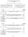
- Fig.1 is a schematic diagram of a flow of a method for measuring a carrier in deactivated state according to an embodiment of this invention, comprising the following steps:
- a user terminal UE receives a configuration mode that does not take effect immediately; if a deactivation control signaling for a carrier is received by the UE or if a carrier timer of the UE expires, then the carrier is switched from activated state to deactivated state, and the UE measures the carrier in deactivated state; or if an activation control signaling for a carrier in deactivated state that is being measured is received by the UE, then the UE terminates measurement of the carrier in deactivated state.
- the UE can reduce its terminal battery power consumption and improve system performance.
- Fig.2 is a schematic diagram of a flow of an embodiment of method for measuring a carrier in deactivated state of this invention, in which a carrier is measured when it is in deactivated state, comprising the following steps:
- the UE can confirm to switch the carrier to deactivated state from activated state by timeout of an internal carrier timer.
- the control signaling can be Medium Access Control (Medium Access Control, MAC) signaling or a physical layer control signaling.
- Medium Access Control Medium Access Control, MAC
- MAC Medium Access Control
- the UE initiates a gap again to perform deactivated carrier measurement only when a deactivation control signaling for the carrier in activated state is once again received by the UE from the BS.
- UE receives a configuration mode that does not take effect immediately, switches a carrier to deactivated state from activated state, initiates a gap to measure the carrier in deactivated state; if an activation control signaling for the carrier in deactivated state that is being measured is received by the UE, then the UE terminates measurement of the carrier in deactivated state.
- Fig.3 is a schematic diagram of a flow of a method for measuring a carrier in deactivated state according to another embodiment of this invention, which is similar to the embodiment shown in Fig.2 , except that the UE receives a newly configured carrier, which is a carrier newly configured by a BS for the UE.
- the newly configured carrier can be carrier in deactivated state or initial state, and then the UE initiates a gap to measure the carrier in deactivated state.
- Fig.4 is a schematic diagram of a flow of a method for measuring a carrier in deactivated state according to another embodiment of this invention, in which if a carrier of the UE is in deactivated state, then the UE can measure the carrier in deactivated state through initiating a gap, shifting RF central frequency, or enabling an idle RF channel.
- the embodiment comprises the following steps:
- the UE When the base station configures a new carrier for the UE, the UE sends RF capability in the band of the carrier only when there are at least two RF channels in the band.
- the UE sends its RF capability information in the same band to the base station, comprising:
- the RF capability information in the same band can only comprise number of RFs supported in the band.
- the RF capability information in the band can further comprise receiving bandwidth supported in the band, the receiving bandwidth is a bandwidth in which the UE can receive data and/or measure bandwidth simultaneously when all RF channels are enabled, the receiving bandwidth and/or measurement bandwidth can be a maximum bandwidth.
- the control signaling may be Medium Access Control (Medium Access Control, MAC) signaling or a physical layer control signaling.
- MAC Medium Access Control
- the UE measuring the carrier in deactivated state through initiating a Gap, shifting the RF central frequency, or enabling an idle RF channel can be pre-configured.
- the pre-configuration can be configuration made by the base station based on the RF capability information reported by the UE, and then the BS can notify configuration information to the UE.
- the pre-configuration can comprise:
- An RF channel can cover multiple bands.
- the UE shifts a RF central frequency, that is, converts RF channel corresponding to activated carriers to a broader bandwidth of the deactivated carriers such that the bandwidth can ensure data reception of activated carriers and measurement of deactivated carriers to be performed simultaneously.
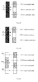
- carriers CC1, CC2, CC3 are carriers in activated state, wherein the UE received a deactivation control signaling for CC1 and CC3.
- A is the RF central frequency.
- the terminal can directly measure CC1 and CC3 without initiating a Gap.
- carriers CC1, CC2, CC3 are carriers in activated state, wherein the UE received a deactivation control signaling for CC3.
- A is the RF central frequency.
- the UE shifts the RF central frequency to B, initiates a gap to measure CC3; or shifts the central frequency back to A to measure CC3.
- carriers CC1, CC2, CC3, CC4 are carriers in activated state, wherein the UE received a deactivation control signaling for CC4.
- RF3 is enabled to measure CC4; or as shown in Fig.4a7 , a Gap is initiated on RF1 to measure CC4.
- step 406 if the UE has initiated a Gap to measure the carrier in deactivated state, then the Gap has to be closed at first to terminate the measurement of the carrier in deactivated state; if the UE has shifted a central frequency to measure the carrier in deactivated state, then measurement of the carrier in deactivated state can be terminated directly; if the UE has enabled an idle RF channel to measure the carrier in deactivated state, then the UE must disable the idle RF channel and then terminate the measurement of the carrier in deactivated state.
- the UE also can send a configuration mode that does not take effect immediately and RF capability information in carrier bands to the BS via a RRC connection reconfiguration completion message, so that the BS can be aware of timings at which the UE initiates and closes a gap based on the RF capability information and the configuration mode that does not take effect immediately of the UE, so that data and/or signaling transmission to the UE can be avoided when a gap is initiated by the UE, as a result, UE data and/or signaling loss can prevented.
- the UE receives a configuration mode that does not take effect immediately; when a deactivation control signaling for a carrier is received by the UE or when a carrier timer of the UE expires, the UE initiates a gap or shifts a central frequency or enable an idle RF channel to measure a carrier in deactivated state; if an activation control signaling for a carrier in deactivated state that is being measured is received by the UE, the UE terminates measurement of the carrier in deactivated state, so that through deactivated carrier measurement control, the UE can reduce terminal battery power consumption and improve system performance.
- Fig.5 is a schematic diagram of a flow of a method for measuring a carrier in deactivated state according to another embodiment of this invention, wherein UE selects a RF channel corresponding to one or more activated carriers to initiate a gap, or shifts RF central frequency, or selects an idle RF channel corresponding to one or more deactivated carriers to measure the carriers in deactivated state, comprising the following steps:
- the RF capability in the band may further comprise receiving bandwidth supported in the band, the receiving bandwidth is a bandwidth in which the UE can receive data and/or measure bandwidth simultaneously when all RF channels are enabled.
- the receiving bandwidth and/or measurement bandwidth may be a maximum bandwidth.
- the RF capability information in the same band can only comprise the number of RF channels supported in the band.
- the RF capability in the band may further comprise receiving bandwidth supported in the band, that is, the receiving bandwidth is a bandwidth in which the UE can receive data and/or measure bandwidth simultaneously when all RF channels are enabled.
- the receiving bandwidth and/or measurement bandwidth may be a maximum bandwidth.
- the carrier is switched from activated state to deactivated state.
- the control signaling can be Medium Access Control (Medium Access Control, MAC) signaling or a physical layer control signaling.
- Medium Access Control Medium Access Control, MAC
- MAC Medium Access Control
- the UE receives a deactivation control signaling for carriers, switches those carriers from activated state to deactivated state, and selects a RF channel corresponding to the one or more activated carriers to measure the carriers in deactivated state by measuring according to the RF capability of the UE, wherein during one measurement period, a non-repeated measurement is performed on at least one carrier in deactivated state on a RF channel corresponding to at least one carrier in activated state.
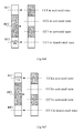
- the measurement of deactivated carriers by the UE can be pre-configured by the BS and the UE. For example, as shown in Fig.5a1 , if carriers CC1, CC2, CC3, CC4 are carriers in activated state, when a deactivation control signaling for CC3 and CC4 is received by the UE, if the UE is going to measure CC3 and CC4, as shown in Fig.5a2 , the UE can initiate a gap on RF1 corresponding to CC1 to measure CC3 and CC4; as shown in Fig.5a3 , the UE also can initiate a gap on RF2 corresponding to CC2 to measure CC3 and CC4; as shown in Fig.5a4 , the UE also can initiate a gap on RF1 to measure CC3 and initiate a gap on RF2 to measure CC4.
- a gap can be initiated on RF2 to measure CC1; as shown in Fig.5a7 ; the central frequency of RF1 can be shifted from A to B to measure CC1; as shown in Fig.5a8, a gap can also be initiated on RF1 to measure CC1.
- the gap has to be closed at first, and then the measurement of the carrier in deactivated state can be terminated; if the UE has shifted a central frequency to measure the carrier in deactivated state, the measurement of the carrier in deactivated state can be terminated directly; if the UE has enabled an idle RF channel to measure the carrier in deactivated state, the UE must disable the idle RF channel and then terminate the measurement of the carrier in deactivated state.
- the UE receives a configuration mode that does not take effect immediately; when a deactivation control signaling for a carrier is received by the UE or when a carrier timer of the UE expires, the UE selects an RF channel corresponding to one or more carriers in activated state to initiate a gap, or shifts an RF central frequency, or selects an idle RF channel corresponding to one or more carriers in activated state, to measure one or more deactivated carriers as selected measuring objects.
- the UE When an activation control signaling for a carrier in deactivated state that is being measured is received by the UE, the UE terminates the measurement of the carrier in deactivated state, so that through controllable deactivated carrier measurement, the UE can reduce terminal battery power consumption and improve system performance.
- Fig.6 is a schematic diagram of a flow of a method for measuring a carrier in deactivated state according to another embodiment of this invention, in which according to configuration information of carriers of a UE, the UE selects measurement configuration information corresponding to the configuration information from a set of measurement configuration information to measure carriers in deactivated state, comprising the following steps.
- the UE sends to BS RF capability in a band of a configured carrier only if there are at least two RF channels in the band.
- the UE sends its RF capability in the same band to the base station, comprising:
- the RF capability in the band may further comprise receiving bandwidth supported in the band, the receiving bandwidth is a bandwidth in which the UE can receive data and/or measure bandwidth simultaneously when all RF channels are enabled; the receiving bandwidth and/or measurement bandwidth can be a maximum bandwidth.
- the RF capability information in the same band can only comprise the number of RF channels supported in the band.
- the RF capability in the band may further comprise receiving bandwidth supported in the band, the receiving bandwidth is a bandwidth in which the UE can receive data and/or measure bandwidth simultaneously when all RF channels are enabled; the receiving bandwidth and/or measurement bandwidth can be a maximum bandwidth.
- the UE For different frequency bands, the UE must use several RF channels. However, for multiple frequencies in the same band, for example, the 3.5G frequency band, a total 5 carriers are supported in 100M; if the UE has a main carrier and auxiliary carriers in one band, the UE may have multiple RF channels, and a deactivated auxiliary carrier can be measured without a gap.
- measurement configuration information set 1 comprises: Table 1 No. Deactivated CC Activated CC Measurement Configuration Information 1 CC1 CC2, CC3, CC4 Initiate a gap on RF3 2 CC2 CC1, CC3, CC4 Initiate a gap on RF2 3 CC3 CC1, CC2, CC4 Initiate a gap on RF2 4 CC4 CC1, CC2, CC3 Initiate a gap on RF1 4 CC1, CC2 CC3, CC4 Initiate a gap on RF3 to measure CC1, initiate a gap on RF2 to measure CC2 5 CC1, CC3 CC2, CC4 Initiate a gap on RF3 to measure CC1, initiate a gap on RF2 to measure CC3 6 CC1, CC4 CC2, CC3 enable RF1 to measure CC1,CC4 7 CC2, CC3 CC1, CC4 enable RF3 to measure
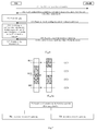
- carriers CC1 and CC4 correspond to RF1 and RF3, respectively, CC2 and CC3 share RF2, for example, when CC2 is a carrier in deactivated state, and CC1, CC3, CC4 are carriers in activated state, Table 2 is measurement configuration information set 2, the UE can select No.2 configuration information from the measurement configuration information set 2 according to configuration information of current configured activated or deactivated carriers, that is, to measure CC2 through shifting central frequency of RF2.
- the measurement configuration information set 2 comprises: Table 2 No. Deactivated CC Activated CC Measurement configuration information 1 CC1 CC2, CC3, CC4 Initiate a gap on RF3 2 CC2 CC1, CC3, CC4 Shift the central frequency of RF2 3 CC3 CC1, CC2, CC4 Shift the central frequency of RF2 4 CC4 CC1, CC2, CC3 Initiate a gap on RF1 4 CC1,CC2 CC3, CC4 Initiate a gap on RF3 to measure CC1; Shift the central frequency of RF2 to measure CC2 5 CC1, CC3 CC2, CC4 Initiate a gap on RF3 to measure CC1; Shift central frequency of RF2 to measure CC3 6 CC1, CC4 CC2, CC3 Enable RF1 to measure CC1, CC4 7 CC2, CC3 CC1, CC4 Enable RF3
- the control signaling can be Medium Access Control (Medium Access Control, MAC) signaling or a physical layer control signaling.
- Medium Access Control Medium Access Control, MAC
- MAC Medium Access Control
- step 605 if the UE has initiated a gap to measure the carrier in deactivated state, the gap has to be closed at first, and then the measurement of the carrier in deactivated state can be terminated; if the UE has shifted a central frequency to measure the carrier in deactivated state, the measurement of the carrier in deactivated state can be terminated directly; if the UE has initiated an idle RF channel to measure the carrier in deactivated state, the UE needs to close the idle RF channel and then terminate the measurement of the carrier in deactivated state.
- Fig.7 is a schematic diagram of a flow of a method for measuring a carrier in deactivated state according to another embodiment of this invention, comprising:
- a BS sends a configuration mode that does not take effect immediately to a UE, to cause the UE to receive a deactivation control signaling for a carrier or a timeout notification of a carrier timer of the UE, switch the carrier from activated state to deactivated state, and measure the carrier in deactivated state; or to cause the UE to terminate measurement of the carrier in deactivated state if an activation control signaling for a carrier in deactivated state that is being measured is received by the UE.
- the UE can reduce terminal battery power consumption and improve system performance.
- Fig.8 is a schematic structure diagram of an apparatus for measuring a carrier in deactivated state according to an embodiment of this invention, comprising:
- the process module is used to, according to the RF capability, select an RF channel corresponding to one or more carriers in activated state to measure the carriers in deactivated state by measuring manner.
- the process module further comprises a process unit 8031 for performing non-repeated measurement on at least one carrier in deactivated state on an RF channel corresponding to at least one carrier in activated state during one measurement period.
- the apparatus further comprises:
- a user terminal UE receives a configuration mode that does not take effect immediately, if a deactivation control signaling for a carrier or a timeout notification of a carrier timer of the UE is received by the UE, the carrier is switched from activated state to deactivated state, and the UE measures the carrier in deactivated state; or if an activation control signaling for a carrier in deactivated state that is being measured is received by the UE, the UE terminates measurement of the carrier in deactivated state.
- the UE can reduce terminal battery power consumption and improve system performance.
- Fig.9 is a schematic structure diagram of a base station of this invention, comprising:
- the BS sends a configuration mode that does not take effect immediately to a user terminal UE; the BS sends a deactivation control signaling for a carrier to the UE, to cause the UE to switch the carrier from activated state to deactivated state when receiving the deactivation control signaling for the carrier, and measure the carrier in deactivated state; or the BS sends an activation control signaling for a carrier in deactivated state that is being measured to the UE, to cause the UE to switch the carrier from activated state to deactivated state when receiving the deactivation control signaling for the carrier, and measure the carrier in deactivated state.
- the UE can reduce terminal battery power consumption and improve system performance.
- the apparatus of the embodiment of this invention is used to perform steps of methods of above embodiments.
- Embodiments of this invention have been described with three or four carriers as an example. However, embodiments of this invention are not limited to the carrier number specified in above embodiments.
- the invention can be implemented in a manner of software and an essential general-purpose hardware platform. Of course, it can be implemented by hardware, but the former is preferred in most cases.
- the technical solutions of the invention or a part thereof contributing to the prior art can essentially be embodied in the form of a software product, which can be stored in a storage medium, which includes several instructions to cause a computer device (which may be a personal computer, a server, a network device, etc.) to perform the methods according to the respective embodiments of the invention.
Landscapes
- Engineering & Computer Science (AREA)
- Computer Networks & Wireless Communication (AREA)
- Signal Processing (AREA)
- Physics & Mathematics (AREA)
- Electromagnetism (AREA)
- Quality & Reliability (AREA)
- Mobile Radio Communication Systems (AREA)
- Circuits Of Receivers In General (AREA)
Abstract
Description
- This application claims priority of Chinese application No.
201010169441.6 - The present invention relates to the field of wireless communication technology, and more specifically, to a method and apparatus for measuring a carrier in deactivated state.
- In the carrier aggregation technique of Long Term Evolution Advance (Long Term Evolution, LTE-Advance), carrier activation and deactivation mechanisms are widely applied to packet service, File Transfer Protocol (File Transfer Protocol, FTP) and the like, wherein arrival of data packets of those services has burst and amount of those data packets is large. Thus, when UE sends/receives data to/from Base Station through activated carrier, the UE has to monitor Physical Downlink Control Channel (Physical Downlink Control Channel, PDCCH) for all carriers kept in activated state. However, continuously monitoring all activated carriers leads to high battery power consumption of the UE. In order to reduce UE battery power consumption, UE can activate carriers required to transmit data only upon the arrival of data packets, and only use a few carriers to keep activated when no data arrives or only a small amount of data arrives.
- In order to guarantee success ratio for activating carriers required for data transmission, avoid data loss and interruption, it is necessary for the BS to measure and acquire signal quality and interference level of carriers in deactivated state before activating those deactivated carriers. However, highly frequent and highly precise measurement may consume battery power of terminals, which degrades system performance.
- A method for measuring a carrier in deactivated state which is capable of improving system performance, is provided in an embodiment of this invention.
- On one aspect, a method for measuring a carrier in deactivated state is provided, comprising:
- receiving a configuration mode that does not take effect immediately by a user terminal UE;
- if a deactivation control signaling for a carrier is received by the UE or if a carrier timer of said UE expires, then switching the carrier from activated state to deactivated state, and measuring the carrier in deactivated state by the UE; or
- if an activation control signaling for a carrier in deactivated state that is being measured is received by the UE, then terminating measurement of the carrier in deactivated state by the UE.
- On another aspect, another method for measuring a carrier in deactivated state is provided, comprising:
- sending a configuration mode that does not take effect immediately by a base station;
- sending an activation control signaling from the base station to a UE, to cause a carrier to switch from activated state to deactivated state when the UE receiving deactivation control signaling for the carrier, and measuring the carrier in deactivated state by said UE; or
- sending an activation control signaling for a carrier in deactivated state that is being measured from the base station to the UE, to cause the UE to terminate measurement of the carrier in deactivated state.
- On another aspect, an apparatus for measuring a carrier in deactivated state is provided, comprising:
- a first receiving module, configured to receive a configuration mode that does not take effect immediately;
- a second receiving module, configured to receive a deactivation control signaling for a carrier or a timeout notification of a carrier timer, or receive an activation control signaling for a carrier in deactivated state that is being measured;
- a process module, configured to, when a deactivation control signaling or a timeout notification is received by the second receiving module, switch the carrier from activated state to deactivated state, and measure the carrier in deactivated state; or when an activation control signaling for a carrier in deactivated state is received by the second receiving module, terminate measurement of the carrier in deactivated state.
- On another aspect, a base station is provided, comprising:
- a first sending module, configured to send a configuration mode that does not take effect immediately;
- a second sending module, configured to send a deactivation control signaling to UE to cause a carrier to switch from activated state to deactivated state when the UE receiving the deactivation control signaling for the carrier, and to cause the UE to measure the carrier in deactivated state; or for sending to the UE an activation control signaling for a carrier in deactivated state that is being measured, to cause the UE to terminate measurement of the carrier in deactivated state.
- In embodiments of this invention, a user terminal UE receives a configuration mode that does not take effect immediately; if a deactivation control signaling for a carrier is received by the UE or if a carrier timer of the UE expires, the carrier is switched from activated state to deactivated state, and the UE measures the carrier in deactivated state; or if an activation control signaling for a carrier in deactivated state that is being measured is received by the UE, then the UE terminates measurement of the carrier in deactivated state. Through enhancing controllability of deactivated carrier measurement, the UE can reduce terminal battery power consumption and improve system performance.
- For a more explicit description of the technical solutions of embodiments of this invention, a brief introduction of accompanying drawings to be used in the description of these embodiments will be given below. Obviously, accompanying drawings described below are merely some embodiments of this invention, for those skilled in the art, other accompanying drawings can be derived from these ones without any creative efforts.
-
Fig.1 is a schematic diagram of a flow of a method for measuring a carrier in deactivated state according to an embodiment of this invention; -
Fig.2 is a schematic diagram of a flow of a method for measuring a carrier in deactivated state according to another embodiment of this invention; -
Fig.3 is a schematic diagram of a flow of a method for measuring a carrier in deactivated state according to another embodiment of this invention; -
Fig.4 is a schematic diagram of a flow of a method for measuring a carrier in deactivated state according to another embodiment of this invention; -
Fig.4a1 is a schematic diagram of a carrier configuration of an embodiment of this invention; -
Fig.4a2 is a schematic diagram of measuring a carrier in deactivated state of an embodiment of this invention; -
Fig.4a3 is a schematic diagram of another carrier configuration of an embodiment of this invention; -
Fig.4a4 is another schematic diagram of measuring a carrier in deactivated state of an embodiment of this invention; -
Fig.4a5 is a schematic diagram of another carrier configuration of an embodiment of this invention; -
Fig.4a6 is another schematic diagram of measuring a carrier in deactivated state of an embodiment of this invention; -
Fig.4a7 is another schematic diagram of measuring a carrier in deactivated state of an embodiment of this invention; -
Fig.5 is a schematic diagram of a flow of a method for measuring a carrier in deactivated state according to another embodiment of this invention; -
Fig.5a1 is a schematic diagram of a carrier configuration of an embodiment of this invention; -
Fig.5a2 is another schematic diagram of measuring a carrier in deactivated state of an embodiment of this invention; -
Fig.5a3 is another schematic diagram of measuring a carrier in deactivated state of an embodiment of this invention; -
Fig.5a4 is another schematic diagram of measuring a carrier in deactivated state of an embodiment of this invention; -
Fig.5a5 is a schematic diagram of a carrier configuration of an embodiment of this invention; -
Fig.5a6 is another schematic diagram of measuring a carrier in deactivated state of an embodiment of this invention; -
Fig.5a7 is another schematic diagram of measuring a carrier in deactivated state of an embodiment of this invention; -
Fig.5a8 is another schematic diagram of measuring a carrier in deactivated state of an embodiment of this invention; -
Fig.6 is a schematic diagram of a flow of a method for measuring a carrier in deactivated state according to another embodiment of this invention; -
Fig.6a is a schematic diagram of a flow of a method for measuring a carrier in deactivated state according to another embodiment of this invention; -
Fig.7 is a schematic diagram of a flow of a method for measuring a carrier in deactivated state according to another embodiment of this invention; -
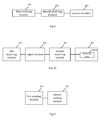
Fig.8 is a schematic structure diagram of an apparatus for measuring a carrier in deactivated state of this invention; -
Fig.8a is another schematic structure diagram of an apparatus for measuring a carrier in deactivated state of this invention; -
Fig.9 is a schematic structure diagram of a base station of this invention. - For making objects, technical solutions and advantages of embodiments of this invention more clear, description will be given below this invention in connection with accompanying drawings. Obviously, embodiments described herein are merely some embodiments of this invention, but not all of them. Based on those embodiments of this invention, other embodiments can occur to those skilled in the art without any creative efforts, all of which fall within the scope of this invention.
-
Fig.1 is a schematic diagram of a flow of a method for measuring a carrier in deactivated state according to an embodiment of this invention, comprising the following steps: - 101. A user terminal UE receives a configuration mode that does not take effect immediately;
- 102a. if a deactivation control signaling for a carrier is received by the UE or if a carrier timer of the UE expires, the carrier is switched from activated state to deactivated state, and the UE measures the carrier in deactivated state; or
- 102b. if an activation control signaling for a carrier in deactivated state that is being measured is received by the UE, then the UE terminates the measurement of the carrier in deactivated state.
- In the embodiment of this invention, a user terminal UE receives a configuration mode that does not take effect immediately; if a deactivation control signaling for a carrier is received by the UE or if a carrier timer of the UE expires, then the carrier is switched from activated state to deactivated state, and the UE measures the carrier in deactivated state; or if an activation control signaling for a carrier in deactivated state that is being measured is received by the UE, then the UE terminates measurement of the carrier in deactivated state. Through controllable deactivated carrier measurement, the UE can reduce its terminal battery power consumption and improve system performance.
-
Fig.2 is a schematic diagram of a flow of an embodiment of method for measuring a carrier in deactivated state of this invention, in which a carrier is measured when it is in deactivated state, comprising the following steps: - 201. UE receives an Radio Resource Control (Radio Resource Control, RRC) connection reconfiguration message sent from BS, wherein the configuration message carries a configuration mode that does not take effect immediately;
- 202. The UE stores the configuration mode that does not take effect immediately;
- 203. The UE sends to the BS an RRC connection reconfiguration completion message;
- 204. The UE receives a deactivation control signaling for a carrier sent from the BS, and switches the carrier from activated state to deactivated state;
- At step 204, the UE can confirm to switch the carrier to deactivated state from activated state by timeout of an internal carrier timer.
- The control signaling can be Medium Access Control (Medium Access Control, MAC) signaling or a physical layer control signaling.
- 205. The UE initiates a time slot Gap to measure the carrier in deactivated state;
- 206. The UE receives an activation control signaling sent from the BS for the carrier in deactivated state that is being measured;
- 207. The UE closes Gap and terminates measurement of the carrier in deactivated state.
- After
step 207, the UE initiates a gap again to perform deactivated carrier measurement only when a deactivation control signaling for the carrier in activated state is once again received by the UE from the BS. - In the embodiment of this invention, UE receives a configuration mode that does not take effect immediately, switches a carrier to deactivated state from activated state, initiates a gap to measure the carrier in deactivated state; if an activation control signaling for the carrier in deactivated state that is being measured is received by the UE, then the UE terminates measurement of the carrier in deactivated state. Through controllable deactivated carrier measurement of the UE, terminal battery power consumption can be reduced and system performance can be improved.
-
Fig.3 is a schematic diagram of a flow of a method for measuring a carrier in deactivated state according to another embodiment of this invention, which is similar to the embodiment shown inFig.2 , except that the UE receives a newly configured carrier, which is a carrier newly configured by a BS for the UE. The newly configured carrier can be carrier in deactivated state or initial state, and then the UE initiates a gap to measure the carrier in deactivated state. -
Fig.4 is a schematic diagram of a flow of a method for measuring a carrier in deactivated state according to another embodiment of this invention, in which if a carrier of the UE is in deactivated state, then the UE can measure the carrier in deactivated state through initiating a gap, shifting RF central frequency, or enabling an idle RF channel. The embodiment comprises the following steps: - 401. The UE sends Radio Frequency (Radio Frequency, RF) capability information of the UE to a base station.
- When the base station configures a new carrier for the UE, the UE sends RF capability in the band of the carrier only when there are at least two RF channels in the band.
- Wherein, the UE sends its RF capability information in the same band to the base station, comprising:
- sending, by the UE, its RF capability information in the same band to the base station. For example, the capability information can be UE-EUTRA-Capability, wherein the RF capability information can comprise a maximum number of RF channels that can be supported in the band and receiving bandwidth supported by each RF, wherein the receiving bandwidth can be a maximum receiving bandwidth.
- If the receiving bandwidth of the RFs in the same band are same, then the RF capability information in the same band can only comprise number of RFs supported in the band.
- The RF capability information in the band can further comprise receiving bandwidth supported in the band, the receiving bandwidth is a bandwidth in which the UE can receive data and/or measure bandwidth simultaneously when all RF channels are enabled, the receiving bandwidth and/or measurement bandwidth can be a maximum bandwidth.
- 402. The UE receives the RRC connection configuration message sent from the base station, wherein the configuration message carries a configuration mode that does not take effect immediately.
- 403. The UE stores the configuration mode.
- 404. a RRC connection reconfiguration completion message is sent to the base station.
- 405. The UE receives a deactivation control signaling for a carrier sent from the base station, and switches the carrier from activated state to deactivated state.
- The control signaling may be Medium Access Control (Medium Access Control, MAC) signaling or a physical layer control signaling.
- 406. The UE measures the carrier in deactivated state through initiating a Gap, shifting RF central frequency, or enabling an idle RF channel.
- The UE measuring the carrier in deactivated state through initiating a Gap, shifting the RF central frequency, or enabling an idle RF channel can be pre-configured. The pre-configuration can be configuration made by the base station based on the RF capability information reported by the UE, and then the BS can notify configuration information to the UE. The pre-configuration can comprise:
- if each of configured carriers corresponds to an RF channel, then the UE receives a deactivated control signaling for a carrier, switches the carrier from activated state to deactivated state, initiates a gap on an enabled RF channel according to the RF capability of the UE to measure the carrier in deactivated state; or
- if each of configured carriers corresponds to a RF channel, then the UE receives a deactivated control signaling for a carrier, switches the carrier from activated state to deactivated state, enables a RF channel corresponding to the carrier in deactivated state according to the RF capability of the UE to perform measurement; or
- if at least two of configured carriers share a RF channel, then the UE receives a deactivated control signaling for a carrier, switches the carrier from activated state to deactivated state, shifts the central frequency of the RF channel according to the RF capability of the UE to measure the carrier in deactivated state; or
- if at least two of configured carriers share a RF channel, the UE receives a deactivated control signaling for a carrier, switches the carrier from activated state to deactivated state, and initiates a gap on an enabled RF channel according to the RF capability of the UE to measure the carrier in deactivated state.
- An RF channel can cover multiple bands. When activated carriers and deactivated carriers are within the same band, particularly, when activated carriers and deactivated carriers are continuous carriers, the UE shifts a RF central frequency, that is, converts RF channel corresponding to activated carriers to a broader bandwidth of the deactivated carriers such that the bandwidth can ensure data reception of activated carriers and measurement of deactivated carriers to be performed simultaneously.
- For example, as shown in
Fig.4a1 , carriers CC1, CC2, CC3 are carriers in activated state, wherein the UE received a deactivation control signaling for CC1 and CC3. A is the RF central frequency. As shown inFig.4a2 , the terminal can directly measure CC1 and CC3 without initiating a Gap. - As shown in
Fig.4a3 , carriers CC1, CC2, CC3 are carriers in activated state, wherein the UE received a deactivation control signaling for CC3. A is the RF central frequency. As shown inFig.4a4 , the UE shifts the RF central frequency to B, initiates a gap to measure CC3; or shifts the central frequency back to A to measure CC3. - As shown in
Fig.4a5, carriers CC1, CC2, CC3, CC4 are carriers in activated state, wherein the UE received a deactivation control signaling for CC4. As shown inFig.4a6 , RF3 is enabled to measure CC4; or as shown inFig.4a7 , a Gap is initiated on RF1 to measure CC4. - 407. The UE receives from the BS an activation control signaling for a carrier in deactivated state that is being measured.
- 408. The UE terminates measurement of the carrier in deactivated state.
- At
step 406, if the UE has initiated a Gap to measure the carrier in deactivated state, then the Gap has to be closed at first to terminate the measurement of the carrier in deactivated state; if the UE has shifted a central frequency to measure the carrier in deactivated state, then measurement of the carrier in deactivated state can be terminated directly; if the UE has enabled an idle RF channel to measure the carrier in deactivated state, then the UE must disable the idle RF channel and then terminate the measurement of the carrier in deactivated state. - With the embodiment of
Fig.4 , the UE also can send a configuration mode that does not take effect immediately and RF capability information in carrier bands to the BS via a RRC connection reconfiguration completion message, so that the BS can be aware of timings at which the UE initiates and closes a gap based on the RF capability information and the configuration mode that does not take effect immediately of the UE, so that data and/or signaling transmission to the UE can be avoided when a gap is initiated by the UE, as a result, UE data and/or signaling loss can prevented. - In the embodiment of this invention, the UE receives a configuration mode that does not take effect immediately; when a deactivation control signaling for a carrier is received by the UE or when a carrier timer of the UE expires, the UE initiates a gap or shifts a central frequency or enable an idle RF channel to measure a carrier in deactivated state; if an activation control signaling for a carrier in deactivated state that is being measured is received by the UE, the UE terminates measurement of the carrier in deactivated state, so that through deactivated carrier measurement control, the UE can reduce terminal battery power consumption and improve system performance.
-
Fig.5 is a schematic diagram of a flow of a method for measuring a carrier in deactivated state according to another embodiment of this invention, wherein UE selects a RF channel corresponding to one or more activated carriers to initiate a gap, or shifts RF central frequency, or selects an idle RF channel corresponding to one or more deactivated carriers to measure the carriers in deactivated state, comprising the following steps: - 501. The UE sends RF capability information of the UE to a base station,
- when the base station configures a new carrier for the UE, the UE sends RF capability within a band of the new carrier to the BS only when there are at least two RF channels in the band,
- wherein, the UE sends RF capability information in the same band to the base station, comprising:
- sending, by the UE, its RF capability information in the same band to the base station, for example, the capability information can be UE-EUTRA-Capability, wherein the RF capability information of the UE can comprise number of RF channels that can be supported in the band and receiving bandwidth supported by each RF channel, wherein the receiving bandwidth can be a maximum receiving bandwidth.
- The RF capability in the band may further comprise receiving bandwidth supported in the band, the receiving bandwidth is a bandwidth in which the UE can receive data and/or measure bandwidth simultaneously when all RF channels are enabled. The receiving bandwidth and/or measurement bandwidth may be a maximum bandwidth.
- If the RF capability in the same band supports the same receiving bandwidth, then the RF capability information in the same band can only comprise the number of RF channels supported in the band.
- The RF capability in the band may further comprise receiving bandwidth supported in the band, that is, the receiving bandwidth is a bandwidth in which the UE can receive data and/or measure bandwidth simultaneously when all RF channels are enabled. The receiving bandwidth and/or measurement bandwidth may be a maximum bandwidth.
- 502. The UE receives an RRC connection configuration message sent from the base station, wherein a configuration message that does not take effect immediately is carried on the configuration message.
- 503. The UE stores the configuration mode that does not take effect immediately.
- 504. Sends an RRC connection reconfiguration completion message to the base station.
- 505. The UE receives a deactivation control signaling for a carrier sent from the base station, and switches the carrier from activated state to deactivated state.
- Alternatively, when a carrier timer of the UE expires, the carrier is switched from activated state to deactivated state.
- The control signaling can be Medium Access Control (Medium Access Control, MAC) signaling or a physical layer control signaling.
- 506. The UE selects an RF channel corresponding to one or more activated carriers to initiate a gap thereon, or shifts an RF central frequency, or selects an idle RF channel corresponding to one or more activated carriers to measure one or more deactivated carriers as selected objects.
- The UE receives a deactivation control signaling for carriers, switches those carriers from activated state to deactivated state, and selects a RF channel corresponding to the one or more activated carriers to measure the carriers in deactivated state by measuring according to the RF capability of the UE, wherein during one measurement period, a non-repeated measurement is performed on at least one carrier in deactivated state on a RF channel corresponding to at least one carrier in activated state.
- The measurement of deactivated carriers by the UE can be pre-configured by the BS and the UE. For example, as shown in
Fig.5a1 , if carriers CC1, CC2, CC3, CC4 are carriers in activated state, when a deactivation control signaling for CC3 and CC4 is received by the UE, if the UE is going to measure CC3 and CC4, as shown inFig.5a2 , the UE can initiate a gap on RF1 corresponding to CC1 to measure CC3 and CC4; as shown inFig.5a3 , the UE also can initiate a gap on RF2 corresponding to CC2 to measure CC3 and CC4; as shown inFig.5a4 , the UE also can initiate a gap on RF1 to measure CC3 and initiate a gap on RF2 to measure CC4. - As shown in
Fig.5a5 , if carriers CC1, CC2, CC3 are carriers in activated state, when a deactivation control signaling for CC1 is received by the UE, if the UE is going to measure CC1 in deactivated state, it can be measured according to configuration information of the BS and the UE. For example, as shown inFig.5a6 , a gap can be initiated on RF2 to measure CC1; as shown inFig.5a7 ; the central frequency of RF1 can be shifted from A to B to measure CC1; as shown inFig.5a8, a gap can also be initiated on RF1 to measure CC1. - 507. The UE receives an activation control signaling sent from the BS for a carrier in deactivated state that is being measured.
- 508. The UE terminates the measurement of the carrier in deactivated state.
- At
step 506, if the UE has initiated a gap to measure the carrier in deactivated state, the gap has to be closed at first, and then the measurement of the carrier in deactivated state can be terminated; if the UE has shifted a central frequency to measure the carrier in deactivated state, the measurement of the carrier in deactivated state can be terminated directly; if the UE has enabled an idle RF channel to measure the carrier in deactivated state, the UE must disable the idle RF channel and then terminate the measurement of the carrier in deactivated state. - In the embodiment of this invention, the UE receives a configuration mode that does not take effect immediately; when a deactivation control signaling for a carrier is received by the UE or when a carrier timer of the UE expires, the UE selects an RF channel corresponding to one or more carriers in activated state to initiate a gap, or shifts an RF central frequency, or selects an idle RF channel corresponding to one or more carriers in activated state, to measure one or more deactivated carriers as selected measuring objects. When an activation control signaling for a carrier in deactivated state that is being measured is received by the UE, the UE terminates the measurement of the carrier in deactivated state, so that through controllable deactivated carrier measurement, the UE can reduce terminal battery power consumption and improve system performance.
-
Fig.6 is a schematic diagram of a flow of a method for measuring a carrier in deactivated state according to another embodiment of this invention, in which according to configuration information of carriers of a UE, the UE selects measurement configuration information corresponding to the configuration information from a set of measurement configuration information to measure carriers in deactivated state, comprising the following steps. - 601. The UE sends RF capability information of the UE to a base station.
- Wherein, at step 601, the UE sends to BS RF capability in a band of a configured carrier only if there are at least two RF channels in the band.
- The UE sends its RF capability in the same band to the base station, comprising:
- sending, by the UE, its RF capability information in the same band to the base station. For example, the capability information can be UE-EUTRA-Capability, wherein the RF capability information of the UE may comprise a number of RF channels that can be supported in the band and receiving bandwidth supported by each RF, wherein the receiving bandwidth can be a maximum receiving bandwidth.
- The RF capability in the band may further comprise receiving bandwidth supported in the band, the receiving bandwidth is a bandwidth in which the UE can receive data and/or measure bandwidth simultaneously when all RF channels are enabled; the receiving bandwidth and/or measurement bandwidth can be a maximum bandwidth.
- If the RF capability in the same band supports the same receiving bandwidth, the RF capability information in the same band can only comprise the number of RF channels supported in the band.
- The RF capability in the band may further comprise receiving bandwidth supported in the band, the receiving bandwidth is a bandwidth in which the UE can receive data and/or measure bandwidth simultaneously when all RF channels are enabled; the receiving bandwidth and/or measurement bandwidth can be a maximum bandwidth.
- For different frequency bands, the UE must use several RF channels. However, for multiple frequencies in the same band, for example, the 3.5G frequency band, a total 5 carriers are supported in 100M; if the UE has a main carrier and auxiliary carriers in one band, the UE may have multiple RF channels, and a deactivated auxiliary carrier can be measured without a gap.
- 602. The BS sends to UE a configuration message with a configuration mode that does not take effect immediately, wherein the configuration message may carry a set of measurement configuration information.
- As shown in Table 2, measurement configuration information set 1 comprises:
Table 1 No. Deactivated CC Activated CC Measurement Configuration Information 1 CC1 CC2, CC3, CC4 Initiate a gap on RF3 2 CC2 CC1, CC3, CC4 Initiate a gap on RF2 3 CC3 CC1, CC2, CC4 Initiate a gap on RF2 4 CC4 CC1, CC2, CC3 Initiate a gap on RF1 4 CC1, CC2 CC3, CC4 Initiate a gap on RF3 to measure CC1, initiate a gap on RF2 to measure CC2 5 CC1, CC3 CC2, CC4 Initiate a gap on RF3 to measure CC1, initiate a gap on RF2 to measure CC3 6 CC1, CC4 CC2, CC3 enable RF1 to measure CC1,CC4 7 CC2, CC3 CC1, CC4 enable RF3 to measure CC2,CC3 8 CC2, CC4 CC1, CC3 Initiate a gap on RF1 to measure CC4, initiate a gap on RF2 to measure CC2 9 CC3, CC4 CC2, CC3 enable RF1 to measure CC1, and initiate a gap to measure CC4 10 CC1, CC2, CC3 CC4 enable RF2 to measure CC2,CC3, and initiate a gap on RF3 to measure CC 1 11 CC2, CC3, CC4 CC1 enable RF2 to measure CC2,CC3, and initiate a gap on RF1 to measure CC4 12 CC1, CC3, CC4 CC2 enable RF1 to measure CC1, and initiate a gap to measure CC4; initiate a gap on RF2 to measure CC3 13 CC1, CC2, CC4 CC3 enable RF3 to measure CC4, and initiate a gap to measure CC1; initiate a gap on RF2 to measure CC2 - As shown in
Fig.6a , carriers CC1 and CC4 correspond to RF1 and RF3, respectively, CC2 and CC3 share RF2, for example, when CC2 is a carrier in deactivated state, and CC1, CC3, CC4 are carriers in activated state, Table 2 is measurement configuration information set 2, the UE can select No.2 configuration information from the measurement configuration information set 2 according to configuration information of current configured activated or deactivated carriers, that is, to measure CC2 through shifting central frequency of RF2. - For example, the measurement configuration information set 2 comprises:
Table 2 No. Deactivated CC Activated CC Measurement configuration information 1 CC1 CC2, CC3, CC4 Initiate a gap on RF3 2 CC2 CC1, CC3, CC4 Shift the central frequency of RF2 3 CC3 CC1, CC2, CC4 Shift the central frequency of RF2 4 CC4 CC1, CC2, CC3 Initiate a gap on RF1 4 CC1,CC2 CC3, CC4 Initiate a gap on RF3 to measure CC1; Shift the central frequency of RF2 to measure CC2 5 CC1, CC3 CC2, CC4 Initiate a gap on RF3 to measure CC1; Shift central frequency of RF2 to measure CC3 6 CC1, CC4 CC2, CC3 Enable RF1 to measure CC1, CC4 7 CC2, CC3 CC1, CC4 Enable RF3 to measure CC2, CC3 8 CC2, CC4 CC1, CC3 Initiate a gap on RF1 to measure CC4; Shift central frequency of RF2 to measure CC2 9 CC3, CC4 CC2, CC3 Enable RF1 to measure CC1, and initiate a gap to measure CC4 10 CC1, CC2, CC3 CC4 Enable RF2 to measure CC2, CC3, and initiate a gap on RF3 to measure CC 1 11 CC2, CC3, CC4 CC1 Enable RF2 to measure CC2, CC3, and initiate a gap on RF1 to measure CC4 12 CC1, CC3, CC4 CC2 Enable RF1 to measure CC1, and initiate a gap to measure CC4; Shift central frequency of RF2 to measure CC3 13 CC1, CC2, CC4 CC3 Enable RF3 to measure CC4, and initiate a gap to measure CC1; Shift the central frequency of RF2 to measure CC2 - 603. The UE stores the configuration message carrying configuration mode that does not take effect immediately.
- 604. The UE receives a deactivation control signaling for a carrier sent from the base station.
- 605. The UE receives a deactivation control signaling for at least one carrier; switches the at least one carrier from activated state to deactivated state; selects measurement configuration information corresponding to the UE configuration information from the measurement configuration information set to measure the carrier in deactivated state.
- The control signaling can be Medium Access Control (Medium Access Control, MAC) signaling or a physical layer control signaling.
- 606. The UE receives an activation control signaling for a carrier in deactivated state that is being measured from the BS.
- 607. The UE terminates measurement of the carrier in deactivated state.
- At step 605, if the UE has initiated a gap to measure the carrier in deactivated state, the gap has to be closed at first, and then the measurement of the carrier in deactivated state can be terminated; if the UE has shifted a central frequency to measure the carrier in deactivated state, the measurement of the carrier in deactivated state can be terminated directly; if the UE has initiated an idle RF channel to measure the carrier in deactivated state, the UE needs to close the idle RF channel and then terminate the measurement of the carrier in deactivated state.
-
Fig.7 is a schematic diagram of a flow of a method for measuring a carrier in deactivated state according to another embodiment of this invention, comprising: - 701. A base station sends a configuration mode that does not take effect immediately;
- 701a. The BS sends a deactivation control signaling to UE to cause the UE to switch a carrier from activated state to deactivated state when receiving the carrier deactivation control signaling, and measure the carrier in deactivated state; or
- 702b. The BS sends an activation control signaling for a carrier in deactivated state that is being measured to the UE, to cause the UE to terminate the measurement of the carrier in deactivated state.
- In the embodiment of this invention, a BS sends a configuration mode that does not take effect immediately to a UE, to cause the UE to receive a deactivation control signaling for a carrier or a timeout notification of a carrier timer of the UE, switch the carrier from activated state to deactivated state, and measure the carrier in deactivated state; or to cause the UE to terminate measurement of the carrier in deactivated state if an activation control signaling for a carrier in deactivated state that is being measured is received by the UE. Through controllable deactivated carrier measurement, the UE can reduce terminal battery power consumption and improve system performance.
-
Fig.8 is a schematic structure diagram of an apparatus for measuring a carrier in deactivated state according to an embodiment of this invention, comprising: - a
first receiving module 801 for receiving a configuration mode that does not take effect immediately; - a
second receiving module 802 for receiving a deactivation control signaling for a carrier or a timeout notification of a carrier timer, or receiving an activation control signaling for a carrier in deactivated state that is being measured; - a
process module 803 for when a deactivation control signaling or a timeout notification is received by the second receiving module, switching the carrier from activated state to deactivated state, and measuring the carrier in deactivated state; or when an activation control signaling for a carrier in deactivated state is received by the second receiving module, terminating measurement of the carrier in deactivated state, - wherein, when a deactivation control signaling or a timeout notification of a carrier of the UE is received by the second receiving module, the carrier is switched from activated state to deactivated state, as shown in
Fig.8a , the process module is particularly used to:- initiate a gap to measure the carrier in deactivated state;
- if each of configured carriers corresponds to an RF channel, according to RF capability, initiate a gap on an enabled RF to measure the carrier in deactivated state;
- if each of configured carriers corresponds to an RF channel, according to RF capability of the UE, enable an RF channel corresponding to the carrier in deactivated state to perform measurement;
- if at least two configured carriers share an RF channel, according to RF capability of the UE, shift central frequency of the RF channel to measure the carrier in deactivated state;
- if at least two configured carriers corresponds ton a RF channel, according to RF capability of the UE, initiate a gap on an enable RF channel to measure the carrier in deactivated state;
- according to the RF capability, select an RF channel corresponding to one or more carriers in activated state to measure carriers in deactivated state by measuring manner.
- Furthermore, the process module is used to, according to the RF capability, select an RF channel corresponding to one or more carriers in activated state to measure the carriers in deactivated state by measuring manner. The process module further comprises a
process unit 8031 for performing non-repeated measurement on at least one carrier in deactivated state on an RF channel corresponding to at least one carrier in activated state during one measurement period. - Furthermore, the apparatus further comprises:
- a
reporting module 804 for reporting RF capability information of the UE, wherein the RF capability information comprises a number of RF channels that are supported in a band of the UE and receiving bandwidth supported by each RF channel; or if RF capability in the same band supports the same receiving bandwidth, the RF capability information of the same band only comprises the number of RF channels supported in the band; or the RF capability information of the band comprises receiving bandwidth supported in the band, that is, receiving bandwidths in which the UE receives data and/or measures bandwidth simultaneously when all RFs are enabled, - wherein, the first receiving module is particularly used to receive a configuration message carrying a configuration mode that does not take effect immediately and a measurement information set, when the second receiving module receives a deactivation control signaling for a carrier or a timeout notification of a carrier timer of the UE, the carrier is switched from activated state to deactivated state; the process module is particularly used to receive a deactivation control signaling for at least one carrier, switch the at least one carrier from activated state to deactivated state; the UE selects measurement configuration information corresponding to the carrier configuration information of the UE from the measurement configuration set according to the carrier configuration information of the UE, to measure the carrier in deactivated state.
- In the embodiment of this invention, a user terminal UE receives a configuration mode that does not take effect immediately, if a deactivation control signaling for a carrier or a timeout notification of a carrier timer of the UE is received by the UE, the carrier is switched from activated state to deactivated state, and the UE measures the carrier in deactivated state; or if an activation control signaling for a carrier in deactivated state that is being measured is received by the UE, the UE terminates measurement of the carrier in deactivated state. Through controllable deactivated carrier measurement, the UE can reduce terminal battery power consumption and improve system performance.
-
Fig.9 is a schematic structure diagram of a base station of this invention, comprising: - a
first sending module 901 for sending a configuration mode that does not take effect immediately; - a
second sending module 902 for sending a deactivation control signaling to a UE to cause the UE to switch a carrier from activated state to deactivated state when receiving the deactivation control signaling for the carrier, and measure the carrier in deactivated state; or for sending the UE an activation control signaling for a carrier in deactivated state that is being measured, to cause the UE to terminate measurement of the carrier in deactivated state, - wherein, the first sending module is particularly used to send configuration information carrying a configuration mode that does not take effect immediately and a measurement information set.
- In the embodiment of this invention, the BS sends a configuration mode that does not take effect immediately to a user terminal UE; the BS sends a deactivation control signaling for a carrier to the UE, to cause the UE to switch the carrier from activated state to deactivated state when receiving the deactivation control signaling for the carrier, and measure the carrier in deactivated state; or the BS sends an activation control signaling for a carrier in deactivated state that is being measured to the UE, to cause the UE to switch the carrier from activated state to deactivated state when receiving the deactivation control signaling for the carrier, and measure the carrier in deactivated state. Through controlling deactivated carrier measurement, the UE can reduce terminal battery power consumption and improve system performance.
- The apparatus of the embodiment of this invention is used to perform steps of methods of above embodiments.
- Embodiments of this invention have been described with three or four carriers as an example. However, embodiments of this invention are not limited to the carrier number specified in above embodiments.
- Through the description of various embodiments above, those skilled in the art can clearly understand that the invention can be implemented in a manner of software and an essential general-purpose hardware platform. Of course, it can be implemented by hardware, but the former is preferred in most cases. Based upon such understanding, the technical solutions of the invention or a part thereof contributing to the prior art can essentially be embodied in the form of a software product, which can be stored in a storage medium, which includes several instructions to cause a computer device (which may be a personal computer, a server, a network device, etc.) to perform the methods according to the respective embodiments of the invention.
- Although this invention has been illustrated and described with reference to some preferred embodiments of this invention, those skilled in the art may understand that various modifications in the form and details can be made without departing from the spirit and scope of this invention.
Claims (17)
- A method for measuring a carrier in deactivated state, characterized by comprising:receiving by a user terminal (UE) a configuration mode that does not take effect immediately;when the UE is in the configuration mode that does not take effect immediately, if a deactivation control signaling for a carrier is received by the UE or if a carrier timer of the UE expires, switching the carrier from activated state to deactivated state, and measuring the carrier in deactivated state; orwhen the UE is in the configuration mode that does not take effect immediately, if an activation control signaling for a carrier in deactivated state that is being measured is received, terminating measurement of the carrier in deactivated state by the UE.
- The method according to claim 1, wherein the receiving by a user terminal UE a configuration mode that does not take effect immediately comprises:receiving an Radio Resource Control (RRC) connection reconfiguration message by the UE, wherein the configuration mode that does not take effect immediately is carried on the RRC connection reconfiguration message; orreceiving by the UE a newly configured carrier message, wherein the configuration mode that does not take effect immediately is carried on the newly configured carrier message.
- The method according to claim 1 or claim 2, wherein the measuring the carrier in deactivated state comprises:initiating a gap by the UE to measure the carrier in deactivated state.
- The method according to claim 1 or claim 2, wherein the measuring the carrier in deactivated state comprises:if each carrier corresponds to an RF channel, initiating a gap on an enabled RF channel by the UE to measure the carrier in deactivated state in the gap; orif each carrier corresponds to an RF channel, enabling an RF channel corresponding to the carrier in deactivated state by the UE to measure the carrier in deactivated state on the corresponding RF channel; orif at least two carriers share an RF channel, shifting a central frequency of the RF channel by the UE to a central frequency of receiving bandwidth of the at least two carriers that is covered by the shared RF channel, and measuring the carrier in deactivated state on the RF channel; orif at least two carriers share an RF channel, initiating a gap by the UE on the shared RF channel that has been enabled to measure the carrier in deactivated state in the gap.
- The method according to claim 1 or claim 2, wherein the measuring the carrier in deactivated state by the UE comprises:according to RF capability of the UE, selecting an RF channel corresponding to one or more carriers in activated state by the UE, enabling the RF channel or initiating a gap on the RF channel to measure the carrier in deactivated state.
- The method according to claim 1, the method further comprises:reporting RF capability information of the UE by the UE,wherein the RF capability information of the UE comprises: a number of RF channels supported by the UE and receiving bandwidth supported by each RF; orif the receiving bandwidth of the RFs of the UE are same, the RF capability information of the UE only comprises the number of RF channels supported by the UE; or,the RF capability information of the UE comprises receiving bandwidth supported by the UE, the receiving bandwidth including bandwidth supported by the UE for data receiving and/or measurement when all RF channels supported by the UE are enabled.
- The method according to claim 6, wherein the receiving by the UE a configuration mode that does not take effect immediately comprises:receiving a configuration message carrying the configuration mode that does not take effect immediately and a measurement information set by the UE.
- The method according to claim 7, wherein the switching the carrier from activated state to deactivated state comprises switching at least one carrier from activated state to deactivated state;
wherein the measuring the carrier in deactivated state by the UE comprises:according to the configuration information of the UE, selecting measurement configuration information corresponding to the configuration information of the UE from the measurement configuration information set to measure the carrier in deactivated state. - A method for measuring a carrier in deactivated state, characterized by comprising:sending a configuration mode that does not take effect immediately to a user terminal UE by a base station, to place the UE in the configuration mode that does not take effect immediately;sending an activation control signaling for a carrier from the base station to the UE, to cause the UE to switch a carrier from activated state to deactivated state when receiving the activation control signaling for the carrier, and measure the carrier in deactivated state; orsending an activation control signaling for a carrier in deactivated state that is being measured from the base station to a the UE, to cause the UE to terminate measurement of the carrier in deactivated state.
- The method according to claim 9, wherein the sending a configuration mode that does not take effect immediately by the base station comprises:sending configuration information carrying the configuration mode that does not take effect immediately and a measurement information set by the base station; orsending an Radio Resource Control (RRC) connection reconfiguration message by the base station, wherein the configuration mode that does not take effect immediately is carried on the RRC connection reconfiguration message; orsending a newly configured carrier message by the base station, wherein the configuration mode that does not take effect immediately is carried on the newly configured carrier message.
- An apparatus for measuring a carrier in deactivated state, characterized by comprising:a first receiving module, configured to receive a configuration mode that does not take effect immediately;a second receiving module, configured to, when in the configuration mode that does not take effect immediately, receive a deactivation control signaling for a carrier or a timeout notification of a carrier timer, or when in the configuration mode that does not take effect immediately, receive an activation control signaling for a carrier in deactivated state that is being measured;a process module, configured to, when a deactivation control signaling or a timeout notification is received by the second receiving module, switch the carrier from activated state to deactivated state, and measure the carrier in deactivated state; and/or when an activation control signaling for a carrier in deactivated state is received by the second receiving module, terminate measurement of the carrier in deactivated state.
- The apparatus according to claim 11, wherein the process module is specifically configured to:initiate a gap to measure the carrier in deactivated state; orif each carrier corresponds to an RF channel, initiate a gap on an enabled RF channel by the UE to measure the carrier in deactivated state within the gap; orif each carrier corresponds to an RF channel, enable an RF channel corresponding to the carrier in deactivated state by the UE to measure the carrier in deactivated state on the corresponding RF channel; orif at least two carriers share an RF channel, shift a central frequency of the RF channel by the UE to a central frequency of the receiving bandwidth of the at least two carriers that is covered by the shared RF channel, and measure the carrier in deactivated state on the RF channel; orif at least two carriers share an RF channel, initiate a gap on the shared RF that has been enabled by the UE to measure the carrier in deactivated state within the gap.
- The apparatus according to claim 11, wherein the process module is specifically configured to:according to RF capability of the UE, select an RF channel corresponding to one or more carriers in activated state, enable the RF channel or initiate a gap on the RF channel to measure the carrier in deactivated state.
- The apparatus according to claim 11, wherein the apparatus further comprises:a reporting module, configured to report RF capability information, the RF capability information comprises a number of RF channels supported by the UE and receiving bandwidth supported by each RF channel; or if multiple RF channels of the UE are capable of supporting the same receiving bandwidth, the RF capability information of the UE only comprises the number of RF channels supported by the UE; or the RF capability information of the UE comprises receiving bandwidth supported by the UE, which includes bandwidth supported by the UE for data receiving and/or measurement when all RF channels supported by the UE are enabled.
- The method according to claim 14, wherein
the first receiving module is specifically configured to receive a configuration message carrying the configuration mode that does not take effect immediately and a measurement information set;
the process module is specifically configured to, when a deactivation control signaling for a carrier or a timeout notification of a carrier timer is received by the second receiving module, switch the carrier from activated state to deactivated state, receive a deactivation control signaling for at least one carrier, switch the at least one carrier from activated state to deactivated state, select measurement configuration information corresponding to the configuration information from the measurement information set to measure the carrier in deactivated state according to the configuration information. - A base station, characterized by comprising:a first sending module, configured to send a configuration mode that does not take effect immediately to a UE to make the UE in the configuration mode that does not take effect;a second sending module, configured to send a deactivation control signaling for a carrier to the UE to cause the UE to switch a carrier from activated state to deactivated state when receiving the deactivation control signaling for the carrier, and measure the carrier in deactivated state; or for sending an activation control signaling for a carrier in deactivated state that is being measured, to cause the UE to terminate measurement of the carrier in deactivated state.
- The base station according to claim 16, wherein the first sending module is specifically configured to:send configuration information carrying the configuration mode that does not take effect immediately and a measurement information set; orsend an Radio Resource Control (RRC) connection reconfiguration message, wherein the configuration mode that does not take effect immediately is carried on the RRC connection reconfiguration message; orsend a newly configured carrier message, wherein the configuration mode that does not take effect immediately is carried on the newly configured carrier message.
Applications Claiming Priority (2)
| Application Number | Priority Date | Filing Date | Title |
|---|---|---|---|
| CN201010169441.6A CN102237936B (en) | 2010-04-30 | 2010-04-30 | Method and device for measuring carriers in deactivated state |
| PCT/CN2011/073593 WO2011134437A1 (en) | 2010-04-30 | 2011-05-03 | Method and apparatus for measuring carrier in deactivation state |
Publications (3)
| Publication Number | Publication Date |
|---|---|
| EP2566073A1 true EP2566073A1 (en) | 2013-03-06 |
| EP2566073A4 EP2566073A4 (en) | 2013-06-19 |
| EP2566073B1 EP2566073B1 (en) | 2017-09-13 |
Family
ID=44860892
Family Applications (1)
| Application Number | Title | Priority Date | Filing Date |
|---|---|---|---|
| EP11774428.4A Active EP2566073B1 (en) | 2010-04-30 | 2011-05-03 | Method and apparatus for measuring carrier in deactivationstate |
Country Status (5)
| Country | Link |
|---|---|
| US (2) | US9031595B2 (en) |
| EP (1) | EP2566073B1 (en) |
| KR (1) | KR101482051B1 (en) |
| CN (1) | CN102237936B (en) |
| WO (1) | WO2011134437A1 (en) |
Families Citing this family (20)
| Publication number | Priority date | Publication date | Assignee | Title |
|---|---|---|---|---|
| CN102237936B (en) * | 2010-04-30 | 2015-01-21 | 华为技术有限公司 | Method and device for measuring carriers in deactivated state |
| WO2012044246A1 (en) * | 2010-09-30 | 2012-04-05 | Telefonaktiebolaget L M Ericsson (Publ) | Methods and nodes for handling measurements |
| WO2014047914A1 (en) * | 2012-09-28 | 2014-04-03 | Broadcom Corporation | Method and apparatus for managing secondary cell measurement |
| WO2015062011A1 (en) * | 2013-10-31 | 2015-05-07 | 华为技术有限公司 | Measurement configuration method, identification and measurement methods, macro base station and ue |
| CN106465344A (en) | 2014-05-02 | 2017-02-22 | 诺基亚通信公司 | Communication via multiple access points |
| US9806871B2 (en) * | 2015-05-17 | 2017-10-31 | Imagination Technologies | Selective sub-carrier processing |
| CN105611553A (en) * | 2015-08-26 | 2016-05-25 | 宇龙计算机通信科技(深圳)有限公司 | Carrier number control method, carrier number control device, terminal and base station |
| US9848384B2 (en) | 2016-02-11 | 2017-12-19 | Imagination Technologies | Receiver deactivation based on dynamic measurements |
| CN110012512B (en) | 2018-01-04 | 2020-07-28 | 维沃移动通信有限公司 | State processing method and related equipment |
| CN110312267B (en) * | 2018-03-27 | 2023-03-21 | 维沃移动通信有限公司 | Method and apparatus for switching bandwidth parts |
| CN110505638B (en) * | 2018-05-16 | 2021-06-04 | 维沃移动通信有限公司 | Measurement control method, terminal and network side equipment |
| CN110896555B (en) * | 2018-09-13 | 2023-06-02 | 华为技术有限公司 | A message processing method and device |
| CN111107613B (en) * | 2018-10-26 | 2022-01-28 | 维沃移动通信有限公司 | Non-connection state measuring method and terminal |
| CN112702750B (en) * | 2019-10-23 | 2022-11-22 | 维沃移动通信有限公司 | Measurement processing method, indication information sending method, terminal and network equipment |
| CN117082555A (en) | 2020-04-20 | 2023-11-17 | 华为技术有限公司 | A measurement configuration method and device |
| CN112205053B (en) * | 2020-07-14 | 2024-01-02 | 北京小米移动软件有限公司 | Method and device for switching active resources, communication equipment and storage medium |
| CN113972922B (en) * | 2020-07-24 | 2024-07-26 | 中国移动通信有限公司研究院 | Interference suppression method and device for air-to-ground communication |
| CN115226217B (en) * | 2021-04-21 | 2025-10-03 | 中国移动通信有限公司研究院 | Auxiliary carrier configuration processing method, device and equipment |
| US11985597B2 (en) * | 2021-08-05 | 2024-05-14 | Qualcomm Incorporated | Techniques for aperiodic discontinuous reception mode communications |
| US12041000B2 (en) | 2021-08-05 | 2024-07-16 | Qualcomm Incorporated | Techniques for communicating data channel transmissions |
Family Cites Families (13)
| Publication number | Priority date | Publication date | Assignee | Title |
|---|---|---|---|---|
| US6208858B1 (en) * | 1998-07-21 | 2001-03-27 | Qualcomm Incorporated | System and method for reducing call dropping rates in a multi-beam communication system |
| US6979992B2 (en) * | 2001-05-16 | 2005-12-27 | Duke Energy Corporation | Portable radiated emissions measurement system |
| US7269414B2 (en) * | 2002-05-28 | 2007-09-11 | Motorola, Inc. | Dynamic mobile station configuration in wireless communications systems and methods therefor |
| EP1615458A1 (en) * | 2003-04-14 | 2006-01-11 | NEC Corporation | Mobile communication system, radio base station containing control device in the mobile communication system and control method thereof |
| CN100518340C (en) * | 2004-07-23 | 2009-07-22 | 华为技术有限公司 | Method of implementing quickly paging of high speed group data service network |
| EP1807951B1 (en) * | 2004-10-29 | 2019-04-10 | Avago Technologies International Sales Pte. Limited | Hierarchical flow-level multi-channel communication |
| CN100466600C (en) * | 2005-03-08 | 2009-03-04 | 华为技术有限公司 | Method for Realizing Resource Reservation in Access Configuration Mode in Next Generation Network |
| US7580713B2 (en) * | 2005-05-12 | 2009-08-25 | Motorola, Inc. | Apparatus and method for establishing an active set of carriers for a receiver |
| CN101841823B (en) * | 2009-03-16 | 2012-06-27 | 电信科学技术研究院 | Method and device for discontinuously monitoring control channels in multicarrier system |
| KR101644150B1 (en) * | 2009-07-12 | 2016-07-29 | 엘지전자 주식회사 | Updating method and apparatus of sleep mode operation |
| KR20110025015A (en) * | 2009-09-01 | 2011-03-09 | 엘지전자 주식회사 | Sleep mode operation method and device in a multi-carrier system |
| US8526888B2 (en) * | 2009-10-01 | 2013-09-03 | Interdigital Patent Holdings, Inc. | Method and apparatus for performing inter-frequency and/or inter-radio access technology measurements |
| CN102237936B (en) * | 2010-04-30 | 2015-01-21 | 华为技术有限公司 | Method and device for measuring carriers in deactivated state |
-
2010
- 2010-04-30 CN CN201010169441.6A patent/CN102237936B/en active Active
-
2011
- 2011-05-03 EP EP11774428.4A patent/EP2566073B1/en active Active
- 2011-05-03 WO PCT/CN2011/073593 patent/WO2011134437A1/en not_active Ceased
- 2011-05-03 KR KR1020127026387A patent/KR101482051B1/en active Active
-
2012
- 2012-10-30 US US13/664,174 patent/US9031595B2/en active Active
-
2015
- 2015-04-24 US US14/695,889 patent/US10009843B2/en active Active
Also Published As
| Publication number | Publication date |
|---|---|
| EP2566073B1 (en) | 2017-09-13 |
| CN102237936A (en) | 2011-11-09 |
| US20150230178A1 (en) | 2015-08-13 |
| US20130053082A1 (en) | 2013-02-28 |
| US9031595B2 (en) | 2015-05-12 |
| WO2011134437A1 (en) | 2011-11-03 |
| EP2566073A4 (en) | 2013-06-19 |
| CN102237936B (en) | 2015-01-21 |
| US10009843B2 (en) | 2018-06-26 |
| KR20120140666A (en) | 2012-12-31 |
| KR101482051B1 (en) | 2015-01-26 |
Similar Documents
| Publication | Publication Date | Title |
|---|---|---|
| EP2566073A1 (en) | Method and apparatus for measuring carrier in deactivationstate | |
| US12574195B2 (en) | Efficient bandwidth adaptation for a wideband carrier | |
| CN109997396B (en) | Wireless communication method and user equipment | |
| US9426839B2 (en) | Method for simultaneously receiving LTE and 1X in SRLTE device | |
| CN104394595B (en) | What WTRU was implemented can operate method, WTRU and the eNB using multiple component carriers | |
| CN105814936B (en) | Method for deactivated secondary component carrier measurement and communication device thereof | |
| US11032142B2 (en) | Switching method, base station and terminal | |
| CN115152262B (en) | Monitoring control method, terminal equipment and network equipment | |
| WO2021104039A1 (en) | Measurement configuration method and apparatus | |
| WO2020258157A1 (en) | Resource set monitoring method, device and storage medium | |
| CN101795461B (en) | Carrier sensing method, terminal device, base station and mobility management entity | |
| US12225546B2 (en) | Feedback method and apparatus, terminal device, and network device | |
| JP2018510563A (en) | Frequency band sharing method, apparatus and system | |
| US12513549B2 (en) | Measurement configuration method and apparatus | |
| US20240236849A1 (en) | Methods, devices, and systems for transmitting and receiving signal for power management | |
| CN102905399B (en) | Method for arranging radio activities and communication device therefor | |
| JP2023516252A (en) | Measuring method, apparatus and terminal device | |
| WO2023216837A1 (en) | Data transmission method and apparatus | |
| WO2025129582A1 (en) | Rrm measurement method and apparatus, and device and storage medium |
Legal Events
| Date | Code | Title | Description |
|---|---|---|---|
| PUAI | Public reference made under article 153(3) epc to a published international application that has entered the european phase |
Free format text: ORIGINAL CODE: 0009012 |
|
| 17P | Request for examination filed |
Effective date: 20120920 |
|
| AK | Designated contracting states |
Kind code of ref document: A1 Designated state(s): AL AT BE BG CH CY CZ DE DK EE ES FI FR GB GR HR HU IE IS IT LI LT LU LV MC MK MT NL NO PL PT RO RS SE SI SK SM TR |
|
| A4 | Supplementary search report drawn up and despatched |
Effective date: 20130517 |
|
| RIC1 | Information provided on ipc code assigned before grant |
Ipc: H04W 52/02 20090101ALI20130513BHEP Ipc: H04W 24/10 20090101ALI20130513BHEP Ipc: H04W 52/28 20090101ALI20130513BHEP Ipc: H04B 17/00 20060101AFI20130513BHEP |
|
| DAX | Request for extension of the european patent (deleted) | ||
| RIC1 | Information provided on ipc code assigned before grant |
Ipc: H04W 72/04 20090101ALI20160114BHEP Ipc: H04W 24/10 20090101ALI20160114BHEP Ipc: H04B 17/391 20150101ALI20160114BHEP Ipc: H04W 52/28 20090101ALI20160114BHEP Ipc: H04B 17/327 20150101ALI20160114BHEP Ipc: H04W 24/02 20090101ALI20160114BHEP Ipc: H04W 52/02 20090101ALI20160114BHEP Ipc: H04B 17/00 20150101AFI20160114BHEP |
|
| 17Q | First examination report despatched |
Effective date: 20160217 |
|
| RAP1 | Party data changed (applicant data changed or rights of an application transferred) |
Owner name: HUAWEI TECHNOLOGIES CO., LTD. |
|
| GRAP | Despatch of communication of intention to grant a patent |
Free format text: ORIGINAL CODE: EPIDOSNIGR1 |
|
| INTG | Intention to grant announced |
Effective date: 20170314 |
|
| GRAS | Grant fee paid |
Free format text: ORIGINAL CODE: EPIDOSNIGR3 |
|
| GRAJ | Information related to disapproval of communication of intention to grant by the applicant or resumption of examination proceedings by the epo deleted |
Free format text: ORIGINAL CODE: EPIDOSDIGR1 |
|
| GRAL | Information related to payment of fee for publishing/printing deleted |
Free format text: ORIGINAL CODE: EPIDOSDIGR3 |
|
| GRAR | Information related to intention to grant a patent recorded |
Free format text: ORIGINAL CODE: EPIDOSNIGR71 |
|
| GRAA | (expected) grant |
Free format text: ORIGINAL CODE: 0009210 |
|
| INTC | Intention to grant announced (deleted) | ||
| AK | Designated contracting states |
Kind code of ref document: B1 Designated state(s): AL AT BE BG CH CY CZ DE DK EE ES FI FR GB GR HR HU IE IS IT LI LT LU LV MC MK MT NL NO PL PT RO RS SE SI SK SM TR |
|
| INTG | Intention to grant announced |
Effective date: 20170808 |
|
| REG | Reference to a national code |
Ref country code: GB Ref legal event code: FG4D |
|
| REG | Reference to a national code |
Ref country code: CH Ref legal event code: EP |
|
| REG | Reference to a national code |
Ref country code: IE Ref legal event code: FG4D |
|
| REG | Reference to a national code |
Ref country code: AT Ref legal event code: REF Ref document number: 929119 Country of ref document: AT Kind code of ref document: T Effective date: 20171015 |
|
| REG | Reference to a national code |
Ref country code: DE Ref legal event code: R096 Ref document number: 602011041577 Country of ref document: DE |
|
| REG | Reference to a national code |
Ref country code: NL Ref legal event code: FP |
|
| REG | Reference to a national code |
Ref country code: LT Ref legal event code: MG4D |
|
| PG25 | Lapsed in a contracting state [announced via postgrant information from national office to epo] |
Ref country code: LT Free format text: LAPSE BECAUSE OF FAILURE TO SUBMIT A TRANSLATION OF THE DESCRIPTION OR TO PAY THE FEE WITHIN THE PRESCRIBED TIME-LIMIT Effective date: 20170913 Ref country code: NO Free format text: LAPSE BECAUSE OF FAILURE TO SUBMIT A TRANSLATION OF THE DESCRIPTION OR TO PAY THE FEE WITHIN THE PRESCRIBED TIME-LIMIT Effective date: 20171213 Ref country code: FI Free format text: LAPSE BECAUSE OF FAILURE TO SUBMIT A TRANSLATION OF THE DESCRIPTION OR TO PAY THE FEE WITHIN THE PRESCRIBED TIME-LIMIT Effective date: 20170913 Ref country code: HR Free format text: LAPSE BECAUSE OF FAILURE TO SUBMIT A TRANSLATION OF THE DESCRIPTION OR TO PAY THE FEE WITHIN THE PRESCRIBED TIME-LIMIT Effective date: 20170913 Ref country code: SE Free format text: LAPSE BECAUSE OF FAILURE TO SUBMIT A TRANSLATION OF THE DESCRIPTION OR TO PAY THE FEE WITHIN THE PRESCRIBED TIME-LIMIT Effective date: 20170913 |
|
| REG | Reference to a national code |
Ref country code: AT Ref legal event code: MK05 Ref document number: 929119 Country of ref document: AT Kind code of ref document: T Effective date: 20170913 |
|
| PG25 | Lapsed in a contracting state [announced via postgrant information from national office to epo] |
Ref country code: GR Free format text: LAPSE BECAUSE OF FAILURE TO SUBMIT A TRANSLATION OF THE DESCRIPTION OR TO PAY THE FEE WITHIN THE PRESCRIBED TIME-LIMIT Effective date: 20171214 Ref country code: BG Free format text: LAPSE BECAUSE OF FAILURE TO SUBMIT A TRANSLATION OF THE DESCRIPTION OR TO PAY THE FEE WITHIN THE PRESCRIBED TIME-LIMIT Effective date: 20171213 Ref country code: RS Free format text: LAPSE BECAUSE OF FAILURE TO SUBMIT A TRANSLATION OF THE DESCRIPTION OR TO PAY THE FEE WITHIN THE PRESCRIBED TIME-LIMIT Effective date: 20170913 Ref country code: LV Free format text: LAPSE BECAUSE OF FAILURE TO SUBMIT A TRANSLATION OF THE DESCRIPTION OR TO PAY THE FEE WITHIN THE PRESCRIBED TIME-LIMIT Effective date: 20170913 Ref country code: ES Free format text: LAPSE BECAUSE OF FAILURE TO SUBMIT A TRANSLATION OF THE DESCRIPTION OR TO PAY THE FEE WITHIN THE PRESCRIBED TIME-LIMIT Effective date: 20170913 |
|
| PG25 | Lapsed in a contracting state [announced via postgrant information from national office to epo] |
Ref country code: PL Free format text: LAPSE BECAUSE OF FAILURE TO SUBMIT A TRANSLATION OF THE DESCRIPTION OR TO PAY THE FEE WITHIN THE PRESCRIBED TIME-LIMIT Effective date: 20170913 Ref country code: RO Free format text: LAPSE BECAUSE OF FAILURE TO SUBMIT A TRANSLATION OF THE DESCRIPTION OR TO PAY THE FEE WITHIN THE PRESCRIBED TIME-LIMIT Effective date: 20170913 Ref country code: CZ Free format text: LAPSE BECAUSE OF FAILURE TO SUBMIT A TRANSLATION OF THE DESCRIPTION OR TO PAY THE FEE WITHIN THE PRESCRIBED TIME-LIMIT Effective date: 20170913 |
|
| PG25 | Lapsed in a contracting state [announced via postgrant information from national office to epo] |
Ref country code: IT Free format text: LAPSE BECAUSE OF FAILURE TO SUBMIT A TRANSLATION OF THE DESCRIPTION OR TO PAY THE FEE WITHIN THE PRESCRIBED TIME-LIMIT Effective date: 20170913 Ref country code: SK Free format text: LAPSE BECAUSE OF FAILURE TO SUBMIT A TRANSLATION OF THE DESCRIPTION OR TO PAY THE FEE WITHIN THE PRESCRIBED TIME-LIMIT Effective date: 20170913 Ref country code: AT Free format text: LAPSE BECAUSE OF FAILURE TO SUBMIT A TRANSLATION OF THE DESCRIPTION OR TO PAY THE FEE WITHIN THE PRESCRIBED TIME-LIMIT Effective date: 20170913 Ref country code: EE Free format text: LAPSE BECAUSE OF FAILURE TO SUBMIT A TRANSLATION OF THE DESCRIPTION OR TO PAY THE FEE WITHIN THE PRESCRIBED TIME-LIMIT Effective date: 20170913 Ref country code: IS Free format text: LAPSE BECAUSE OF FAILURE TO SUBMIT A TRANSLATION OF THE DESCRIPTION OR TO PAY THE FEE WITHIN THE PRESCRIBED TIME-LIMIT Effective date: 20180113 Ref country code: SM Free format text: LAPSE BECAUSE OF FAILURE TO SUBMIT A TRANSLATION OF THE DESCRIPTION OR TO PAY THE FEE WITHIN THE PRESCRIBED TIME-LIMIT Effective date: 20170913 |
|
| REG | Reference to a national code |
Ref country code: DE Ref legal event code: R097 Ref document number: 602011041577 Country of ref document: DE |
|
| PLBE | No opposition filed within time limit |
Free format text: ORIGINAL CODE: 0009261 |
|
| STAA | Information on the status of an ep patent application or granted ep patent |
Free format text: STATUS: NO OPPOSITION FILED WITHIN TIME LIMIT |
|
| PG25 | Lapsed in a contracting state [announced via postgrant information from national office to epo] |
Ref country code: DK Free format text: LAPSE BECAUSE OF FAILURE TO SUBMIT A TRANSLATION OF THE DESCRIPTION OR TO PAY THE FEE WITHIN THE PRESCRIBED TIME-LIMIT Effective date: 20170913 |
|
| 26N | No opposition filed |
Effective date: 20180614 |
|
| PG25 | Lapsed in a contracting state [announced via postgrant information from national office to epo] |
Ref country code: SI Free format text: LAPSE BECAUSE OF FAILURE TO SUBMIT A TRANSLATION OF THE DESCRIPTION OR TO PAY THE FEE WITHIN THE PRESCRIBED TIME-LIMIT Effective date: 20170913 |
|
| REG | Reference to a national code |
Ref country code: CH Ref legal event code: PL |
|
| REG | Reference to a national code |
Ref country code: BE Ref legal event code: MM Effective date: 20180531 |
|
| PG25 | Lapsed in a contracting state [announced via postgrant information from national office to epo] |
Ref country code: MC Free format text: LAPSE BECAUSE OF FAILURE TO SUBMIT A TRANSLATION OF THE DESCRIPTION OR TO PAY THE FEE WITHIN THE PRESCRIBED TIME-LIMIT Effective date: 20170913 |
|
| REG | Reference to a national code |
Ref country code: IE Ref legal event code: MM4A |
|
| PG25 | Lapsed in a contracting state [announced via postgrant information from national office to epo] |
Ref country code: CH Free format text: LAPSE BECAUSE OF NON-PAYMENT OF DUE FEES Effective date: 20180531 Ref country code: LI Free format text: LAPSE BECAUSE OF NON-PAYMENT OF DUE FEES Effective date: 20180531 |
|
| PG25 | Lapsed in a contracting state [announced via postgrant information from national office to epo] |
Ref country code: LU Free format text: LAPSE BECAUSE OF NON-PAYMENT OF DUE FEES Effective date: 20180503 |
|
| PG25 | Lapsed in a contracting state [announced via postgrant information from national office to epo] |
Ref country code: IE Free format text: LAPSE BECAUSE OF NON-PAYMENT OF DUE FEES Effective date: 20180503 Ref country code: FR Free format text: LAPSE BECAUSE OF NON-PAYMENT OF DUE FEES Effective date: 20180531 |
|
| PG25 | Lapsed in a contracting state [announced via postgrant information from national office to epo] |
Ref country code: BE Free format text: LAPSE BECAUSE OF NON-PAYMENT OF DUE FEES Effective date: 20180531 |
|
| PG25 | Lapsed in a contracting state [announced via postgrant information from national office to epo] |
Ref country code: MT Free format text: LAPSE BECAUSE OF NON-PAYMENT OF DUE FEES Effective date: 20180503 |
|
| PG25 | Lapsed in a contracting state [announced via postgrant information from national office to epo] |
Ref country code: TR Free format text: LAPSE BECAUSE OF FAILURE TO SUBMIT A TRANSLATION OF THE DESCRIPTION OR TO PAY THE FEE WITHIN THE PRESCRIBED TIME-LIMIT Effective date: 20170913 |
|
| PG25 | Lapsed in a contracting state [announced via postgrant information from national office to epo] |
Ref country code: HU Free format text: LAPSE BECAUSE OF FAILURE TO SUBMIT A TRANSLATION OF THE DESCRIPTION OR TO PAY THE FEE WITHIN THE PRESCRIBED TIME-LIMIT; INVALID AB INITIO Effective date: 20110503 Ref country code: PT Free format text: LAPSE BECAUSE OF FAILURE TO SUBMIT A TRANSLATION OF THE DESCRIPTION OR TO PAY THE FEE WITHIN THE PRESCRIBED TIME-LIMIT Effective date: 20170913 |
|
| PG25 | Lapsed in a contracting state [announced via postgrant information from national office to epo] |
Ref country code: CY Free format text: LAPSE BECAUSE OF FAILURE TO SUBMIT A TRANSLATION OF THE DESCRIPTION OR TO PAY THE FEE WITHIN THE PRESCRIBED TIME-LIMIT Effective date: 20170913 Ref country code: MK Free format text: LAPSE BECAUSE OF NON-PAYMENT OF DUE FEES Effective date: 20170913 |
|
| PG25 | Lapsed in a contracting state [announced via postgrant information from national office to epo] |
Ref country code: AL Free format text: LAPSE BECAUSE OF FAILURE TO SUBMIT A TRANSLATION OF THE DESCRIPTION OR TO PAY THE FEE WITHIN THE PRESCRIBED TIME-LIMIT Effective date: 20170913 |
|
| PGFP | Annual fee paid to national office [announced via postgrant information from national office to epo] |
Ref country code: NL Payment date: 20250409 Year of fee payment: 15 |
|
| PGFP | Annual fee paid to national office [announced via postgrant information from national office to epo] |
Ref country code: DE Payment date: 20250402 Year of fee payment: 15 |
|
| PGFP | Annual fee paid to national office [announced via postgrant information from national office to epo] |
Ref country code: GB Payment date: 20250401 Year of fee payment: 15 |