EP2566003A2 - Energy distribution assembly with a control device and a current sensor - Google Patents
Energy distribution assembly with a control device and a current sensor Download PDFInfo
- Publication number
- EP2566003A2 EP2566003A2 EP12182245A EP12182245A EP2566003A2 EP 2566003 A2 EP2566003 A2 EP 2566003A2 EP 12182245 A EP12182245 A EP 12182245A EP 12182245 A EP12182245 A EP 12182245A EP 2566003 A2 EP2566003 A2 EP 2566003A2
- Authority
- EP
- European Patent Office
- Prior art keywords
- control device
- current
- voltage
- current sensor
- energy
- Prior art date
- Legal status (The legal status is an assumption and is not a legal conclusion. Google has not performed a legal analysis and makes no representation as to the accuracy of the status listed.)
- Withdrawn
Links
Images

Classifications
-
- H—ELECTRICITY
- H02—GENERATION; CONVERSION OR DISTRIBUTION OF ELECTRIC POWER
- H02J—CIRCUIT ARRANGEMENTS OR SYSTEMS FOR SUPPLYING OR DISTRIBUTING ELECTRIC POWER; SYSTEMS FOR STORING ELECTRIC ENERGY
- H02J3/00—Circuit arrangements for ac mains or ac distribution networks
- H02J3/28—Arrangements for balancing of the load in a network by storage of energy
- H02J3/32—Arrangements for balancing of the load in a network by storage of energy using batteries with converting means
Definitions
- the invention relates to an energy distribution system with a control device and a current sensor according to the preamble of claim 1, as well as a current sensor which can be advantageously used.
- German Utility Model DE 20 2010 012 658 U1 is a control unit for controlling, feeding and storing electrical energy from the power grid with the involvement of renewable or other local energy sources known.
- Such power distribution systems are used for the energy management of particular regenerative energy sources with temporally changing output power, such.
- the following explanation relates purely by way of example and without limiting the general public to a photovoltaic system.
- Photovoltaic systems for the at least supportive energy supply of buildings are becoming increasingly widespread.
- a problem of such systems is that the electrical power output of the photovoltaic generator over the course of the day is subject to strong fluctuations and practically never exactly the instantaneous energy consumption of the installed in the building consumer, hereinafter referred to briefly as local installation corresponds.
- a photovoltaic system can generate an electric power that goes far beyond the electrical power requirements of the local installation, so that excess electrical energy can be fed into a public power grid.
- electrical energy generated by a photovoltaic system and also consumed in the local installation itself is provided with a higher rate of compensation than the energy directly fed into the grid. It is therefore desirable to optimize the so-called self-consumption.
- self-consumption it is expected that the price of electricity taken from the grid will continue to increase in the future and increase over the next few years over the rate of payment for photovoltaically generated energy.
- Another advantage of self-consumption is a relief of the networks, since depending on the dimensions of the system, the solar coverage can be further increased.
- Photovoltaic systems with self-consumption optimization have as energy storage batteries, which can store several kilowatt hours of electrical energy.
- the supply or removal of electrical energy from the public voltage network takes place here only when the buffering capacity of the energy storage is exceeded or if this is profitable due to daytime electricity tariffs.
- bidirectional energy meters It is customary to switch a bidirectionally measuring electronic energy meter into the main line between the power supply and the local installation. Such energy meters detect both the removal and the supply of electrical energy into the voltage network by detecting current and voltage values and computationally processed to electrical performance data. It is known that bidirectional energy meters Output performance data via an optical interface. Unfortunately, there are currently no standardized protocols for this purpose, so that the software of the control device must be adapted to the respective energy meter for the purpose of transmitting the data to the control device.
- the object was to provide an energy distribution system which does not have these disadvantages.
- control device detects the current values and voltage values present at each phase conductor of the output line
- current sensor detects the current in the main line between the local installation and the public voltage network at each phase conductor by means of an inductive current transformer.
- the energy distribution system enables detection of the electric power transmitted via the main line without the data output of the bi-directional energy meter located in the main line must be accessed. There is therefore no need to choose the energy meter with regard to the software of the control device or conversely to adapt the software of the control device specifically to the energy meter used.
- a suitable for this purpose current sensor consists of three inductive current transformers, each detecting the current flowing in a phase conductor current.
- a single-phase design is also conceivable here.
- An advantageous embodiment of a current transformer consists of a toroidal coil, through the ring opening a phase conductor can be passed.
- a further advantageous embodiment of a current transformer has a plurality of connectable core elements which can be wrapped around a phase conductor and then connected to form an annular or polygonal executed closed core.
- the advantage here is that the electrical connection of already connected phase conductors for applying the current transformer does not have to be separated, whereby the installation of the current transformer is particularly simple.
- Such current transformers are already commercially available as individual parts. Advantageously, they require only a small installation effort, since they can be mounted, for example, directly on a DIN top hat rail. Since inductive current transformers are passive measuring systems, they advantageously also need no separate power supply. In addition, a galvanic separation from the potential of the conductor to be measured is achieved by the use of such current transformers, which significantly simplifies the preparation of the measurement signal in the control device.
- control device by recording the temporal current waveform on all three phase conductors of a three-phase alternating current and an internal detection of the associated temporal voltage curve all data for calculating active, reactive and apparent power of the system has available and can use these state variables for energy management ,
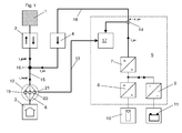
- the central element of the power distribution system is a control device 5, to which a solar generator 10 and an energy storage 11 are connected.
- the solar generator 10 consists of a plurality of, not shown here in detail, photovoltaic modules, which in turn each have a plurality of solar cells.
- the solar generator 10 converts radiant energy of the sun into electrical energy, wherein the electrical power output varies more or less strongly as a function of the momentary incidence of light during the course of the day.
- the energy storage 11 is provided, which preferably consists of an interconnection of accumulators with a total capacity of the order of several kilowatt hours.
- the energy storage 11 can be charged by the electrical energy emitted by the solar generator 10. In addition, he can at times, in where the power requirement of the local installation 3 exceeds the output power of the solar generator 10, compensate for the lack of power.
- a DC / DC converter 8, 9 is assigned within the control device 5, which bring the output from the solar generator 10 and the energy storage 11 voltages to the voltage required for feeding into the public power grid 1 voltage level.
- the output voltages of the DC / DC converters 8, 9 are converted by a DC / AC converter 7 into a multi-phase AC voltage suitable for supplying the local installation 3 or for feeding into the voltage network 1.
- the DC / DC converter 9 must be bidirectional in order to allow charging of the energy store 11 from the output voltage of the DC / DC converter 8.
- the output voltage of the DC / AC converter 7 is fed to an output line 18, which is connected via a solar energy meter 4 with a connection node 16 of the main line 15.
- the solar energy meter 4 is used to determine the energy supplied by the solar generator 10 and the energy storage 11 in the local installation 3 and the voltage network 1.
- a bidirectional measuring electronic energy meter 2 is looped, which detects both the public power grid 1 related and fed into the public power grid 1 amount of energy ,
- a universally applicable current sensor 12 which provides an inductive current transformer 19 for each phase conductor 6 of the main line 15.
- the current transformers 19 are each formed as a toroidal coil, each consisting of a toroidal core 20, through the ring opening in each case a phase conductor 6 is passed and to which a coil winding 21 is applied, on which a current-proportional measurement signal can be removed.
- the measuring signals of all three current transformers 19 are fed via a multi-wire signal line 13 and a signal conditioning in the control device 5 to a measuring input of a microcontroller 17.
- the microcontroller 17 is a central component of the control device 5 and controls the internal and external processes of the control device 5.
- the quantities u_pv, i_pv, i_grid and i_local are to be understood as single-phase or multi-phase, even if they are mentioned in the text only in the singular.
- the voltage value u_pv at the output line 18 is detected by the voltage sensor 14 still within the control device 5.
- the detected voltage value u_pv is assumed to be representative for the entire energy distribution system. This is possible with sufficient accuracy, since no significant voltage drops can be expected on the meters and on the wiring.
- the current measurement must be done outside the control device 5.
- the current sensor 12 is provided with passive inductive current transformers 19 in order to transmit the instantaneous value of the current i_grid or i_local isolated to a secondary circuit.
- This secondary current corresponds to the time profile of the current to be measured and, as translated by the converter ratio of the current transformer, is detected by the control device 5.
- the signal is then measured by the microcontroller 17.
- connection point 16 three inflowing streams i_local, i_pv, i_grid be assigned, where i_local is the local installation related partial flow, i_pv of the output line 18 of the control device 5 inflowing partial flow and i_grid derived from the public power grid 1 partial flow.
- i_local is the local installation related partial flow
- i_pv is the local installation related partial flow
- i_grid derived from the public power grid 1 partial flow.
- the current sensor 12 detects at the three phase conductors 6, the instantaneous values of 1_local ( FIG. 1 ) or i_grid ( FIG. 2 ).
- i_pv and i_local are measured.
- the control device 5 can thus determine all relevant for an energy management electrical performance data. It is essential that all current and voltage values are detected as instantaneous values and are measured and processed by the microcontroller 17 at a high repetition frequency of, for example, 16,000 Hz.
- control device 5 can advantageously determine both real and reactive powers and apparent powers of the entire device.
- FIGS. 1 and 2 illustrated embodiments of an energy distribution device to each other functionally equivalent.
- the current measurement beyond the connection node 16 is removed from the energy meter 2, since the in the FIG. 2 shown current measuring point in the vicinity of the energy meter 2 is often not freely accessible, because the corresponding line sections are sealed.
- the embodiment according to the FIG. 1 is easily realizable even in such a case.
Landscapes
- Engineering & Computer Science (AREA)
- Power Engineering (AREA)
- Remote Monitoring And Control Of Power-Distribution Networks (AREA)
- Supply And Distribution Of Alternating Current (AREA)
Abstract
Description
Die Erfindung betrifft eine Energieverteilungsanlage mit einer Steuervorrichtung und einem Stromsensor nach dem Oberbegriff des Anspruchs 1, sowie einen hierbei vorteilhaft verwendbaren Stromsensor.The invention relates to an energy distribution system with a control device and a current sensor according to the preamble of
Aus der deutschen Gebrauchsmusterschrift
Derartige Energieverteilungsanlagen finden Anwendung für das Energiemanagement von insbesondere regenerativen Energiequellen mit zeitlich wechselnder Ausgangsleistung, wie z. B. Photovoltaik- oder Windkraftanlagen. Die folgende Erläuterung bezieht sich rein beispielhaft und ohne Beschränkung der Allgemeinheit auf eine Photovoltaikanlage.Such power distribution systems are used for the energy management of particular regenerative energy sources with temporally changing output power, such. B. photovoltaic or wind turbines. The following explanation relates purely by way of example and without limiting the general public to a photovoltaic system.
Photovoltaikanlagen zur zumindest unterstützenden Energieversorgung von Gebäuden finden zunehmende Verbreitung. Ein Problem derartiger Anlagen besteht darin, dass die elektrische Leistungsabgabe des Photovoltaikgenerators über den Tagesverlauf starken Schwankungen unterliegt und praktisch nie genau dem momentanen Energiebedarf der im Gebäude installierten Verbraucher, im folgenden kurz als lokale Installation bezeichnet, entspricht.Photovoltaic systems for the at least supportive energy supply of buildings are becoming increasingly widespread. A problem of such systems is that the electrical power output of the photovoltaic generator over the course of the day is subject to strong fluctuations and practically never exactly the instantaneous energy consumption of the installed in the building consumer, hereinafter referred to briefly as local installation corresponds.
So kann eine Photovoltaikanlage während der hellen Tagesstunden eine elektrische Leistung erzeugen, die weit über den elektrischen Leistungsbedarf der lokalen Installation hinausgeht, so dass überschüssige elektrische Energie in ein öffentliches Spannungsnetz eingespeist werden kann. In der übrigen Zeit kann es dagegen notwendig sein, zum Ausgleich von Energiedefiziten, dem öffentlichen Spannungsnetz elektrische Energie zu entnehmen. Gegenwärtig wird elektrische Energie, die von einer Photovoltaikanlage erzeugt und auch in der lokalen Installation selbst verbraucht wird, mit einem größeren Vergütungssatz versehen als die direkt in das Netz eingespeiste Energie. Es ist daher wünschenswert, den sogenannten Eigenverbrauch zu optimieren. Darüber hinaus ist in Zukunft zu erwarten, dass der Preis für aus dem Stromnetz entnommene elektrische Energie weiter steigt und in den nächsten Jahren über den Vergütungssatz für photovoltaisch erzeugte Energie ansteigt. Ein weiterer Vorteil des Eigenverbrauchs ist eine Entlastung der Netze, da je nach Dimensionierung der Anlage der solare Deckungsgrad weiter gesteigert werden kann.Thus, during the bright hours of the day, a photovoltaic system can generate an electric power that goes far beyond the electrical power requirements of the local installation, so that excess electrical energy can be fed into a public power grid. In the rest On the other hand, it may be necessary to take electrical energy from the public power grid to compensate for energy shortages. At present, electrical energy generated by a photovoltaic system and also consumed in the local installation itself is provided with a higher rate of compensation than the energy directly fed into the grid. It is therefore desirable to optimize the so-called self-consumption. In addition, it is expected that the price of electricity taken from the grid will continue to increase in the future and increase over the next few years over the rate of payment for photovoltaically generated energy. Another advantage of self-consumption is a relief of the networks, since depending on the dimensions of the system, the solar coverage can be further increased.
Photovoltaikanlagen mit einer Eigenverbrauchsoptimierung weisen als Energiespeicher Akkumulatoren auf, welche mehrere Kilowattstunden elektrischer Energie speichern können. Die Einspeisung bzw. Entnahme elektrischer Energie aus dem öffentlichen Spannungsnetz erfolgt hier nur noch dann, wenn das Pufferungsvermögen des Energiespeichers überschritten wird oder wenn dies aufgrund von tageszeitbezogenen Stromtarifen einträglich ist.Photovoltaic systems with self-consumption optimization have as energy storage batteries, which can store several kilowatt hours of electrical energy. The supply or removal of electrical energy from the public voltage network takes place here only when the buffering capacity of the energy storage is exceeded or if this is profitable due to daytime electricity tariffs.
Die Optimierung des Eigenverbrauchs erfordert ein Energiemanagement durch eine Steuervorrichtung. Zur Generierung von Eingangsgrößen für die Steuervorrichtung ist eine Messung der mit dem öffentlichen Spannungsnetz ausgetauschten elektrischen Leistung erforderlich.The optimization of self-consumption requires energy management by a control device. In order to generate input variables for the control device, it is necessary to measure the electrical power exchanged with the public power supply.
Üblich ist es, einen bidirektional messenden elektronischen Energiezähler in die Hauptleitung zwischen dem Spannungsnetz und der lokalen Installation zu schalten. Solche Energiezähler erfassen sowohl die Entnahme als auch die Einspeisung elektrischer Energie in das Spannungsnetz, indem sie Strom- und Spannungswerte erfassen und rechnerisch zu elektrischen Leistungsdaten aufbereiten. Dabei ist es bekannt, dass bidirektionale Energiezähler Leistungsdaten über eine optische Schnittstelle ausgeben können. Leider liegen hierzu derzeit noch keine standardisierten Protokolle vor, so dass zur Übertragung der Daten an die Steuervorrichtung die Software der Steuervorrichtung an den jeweiligen Energiezähler anzupassen ist.It is customary to switch a bidirectionally measuring electronic energy meter into the main line between the power supply and the local installation. Such energy meters detect both the removal and the supply of electrical energy into the voltage network by detecting current and voltage values and computationally processed to electrical performance data. It is known that bidirectional energy meters Output performance data via an optical interface. Unfortunately, there are currently no standardized protocols for this purpose, so that the software of the control device must be adapted to the respective energy meter for the purpose of transmitting the data to the control device.
Sind diese Protokolle nicht offengelegt, so ist das Auslesen besonders schwierig oder sogar unmöglich. Hierdurch ergeben sich Kompatibilitätsprobleme zwischen den Produkten verschiedener Hersteller, und zwar insbesondere dann, wenn ein Anwender die Steuervorrichtung oder den Energiezähler gegen ein Gerät anderen Typs austauschen möchte. Ein weiteres Problem ist, dass die zur Verfügung gestellten Daten nur in einem groben Zeitraster zur Verfügung stehen.If these protocols are not disclosed, reading them out is particularly difficult or even impossible. This results in compatibility problems between the products of different manufacturers, especially when a user wants to exchange the control device or the energy meter for a device of a different type. Another problem is that the data provided is only available in a rough time frame.
Es stellte sich die Aufgabe, eine Energieverteilungsanlage zu schaffen, welche diese Nachteile nicht aufweist.The object was to provide an energy distribution system which does not have these disadvantages.
Diese Aufgabe wird erfindungsgemäß dadurch gelöst, dass die Steuervorrichtung die an jedem Phasenleiter der Ausgangsleitung vorliegenden Stromwerte und Spannungswerte erfasst, und dass der Stromsensor den Strom in der Hauptleitung zwischen der lokalen Installation und dem öffentlichen Spannungsnetz an jedem Phasenleiter durch jeweils einen induktiven Stromwandler erfasst.
Aus der oben erwähnten
From the above
Die erfindungsgemäße Energieverteilungsanlage ermöglicht eine Erfassung der über die Hauptleitung übertragenen elektrischen Leistungen, ohne dass auf die Datenausgabe des in der Hauptleitung liegenden bidirektionalen Energiezählers zugegriffen werden muss. Es besteht daher keine Notwendigkeit, den Energiezähler im Hinblick auf die Software der Steuervorrichtung zu wählen oder umgekehrt, die Software der Steuervorrichtung speziell an den verwendeten Energiezähler anzupassen.The energy distribution system according to the invention enables detection of the electric power transmitted via the main line without the data output of the bi-directional energy meter located in the main line must be accessed. There is therefore no need to choose the energy meter with regard to the software of the control device or conversely to adapt the software of the control device specifically to the energy meter used.
Es ist lediglich ein vergleichsweise kostengünstig ausführbarer mehrphasig messender Stromsensor vorzusehen, der zusammen mit der Steuervorrichtung verwendbar ist. Ein hierzu geeigneter Stromsensor besteht aus drei induktiven Stromwandlern, die jeweils den in einem Phasenleiter fließenden Strom erfassen. Eine einphasige Ausführung ist hier ebenfalls denkbar. Eine vorteilhafte Ausführung eines Stromwandlers besteht aus einer Ringkernspule, durch deren Ringöffnung ein Phasenleiter hindurchführbar ist.It is merely a comparatively inexpensive executable multi-phase measuring current sensor to provide, which is used together with the control device. A suitable for this purpose current sensor consists of three inductive current transformers, each detecting the current flowing in a phase conductor current. A single-phase design is also conceivable here. An advantageous embodiment of a current transformer consists of a toroidal coil, through the ring opening a phase conductor can be passed.
Eine weitere vorteilhafte Ausführung eines Stromwandlers weist mehrere miteinander verbindbare Kernelemente auf, die um einen Phasenleiter herumgelegt und dann zu einem ringförmigen oder mehreckig ausgeführten geschlossenen Kern verbunden werden können. Vorteilhaft hierbei ist, dass die elektrische Verbindung von bereits angeschlossenen Phasenleitern zum Anlegen der Stromwandler nicht aufgetrennt werden muss, wodurch die Montage der Stromwandler besonders einfach wird.A further advantageous embodiment of a current transformer has a plurality of connectable core elements which can be wrapped around a phase conductor and then connected to form an annular or polygonal executed closed core. The advantage here is that the electrical connection of already connected phase conductors for applying the current transformer does not have to be separated, whereby the installation of the current transformer is particularly simple.
Derartige Stromwandler sind als Einzelteile bereits kostengünstig im Handel erhältlich. Vorteilhafterweise erfordern sie nur einen geringen Installationsaufwand, da sie beispielsweise direkt auf einer DIN-Hutschiene montierbar sind. Da induktive Stromwandler passiv messende Systeme sind, benötigen sie vorteilhafterweise auch keine eigene Spannungsversorgung. Darüber hinaus wird durch den Einsatz derartiger Stromwandler eine galvanische Trennung vom Potential des zu messenden Leiters erreicht, was die Aufbereitung des Messsignals in der Steuervorrichtung deutlich vereinfacht.Such current transformers are already commercially available as individual parts. Advantageously, they require only a small installation effort, since they can be mounted, for example, directly on a DIN top hat rail. Since inductive current transformers are passive measuring systems, they advantageously also need no separate power supply. In addition, a galvanic separation from the potential of the conductor to be measured is achieved by the use of such current transformers, which significantly simplifies the preparation of the measurement signal in the control device.
Besonders vorteilhaft ist, dass die Steuervorrichtung durch Erfassung des zeitlichen Stromverlaufs an allen drei Phasenleitern eines Dreiphasenwechselstroms und einer internen Erfassung des zugehörigen zeitlichen Spannungsverlaufs sämtliche Daten zur Berechnung von Wirk-, Blind- und Scheinleistungen der Anlage zur Verfügung hat und diese Zustandsgrößen zum Energiemanagement verwenden kann.It is particularly advantageous that the control device by recording the temporal current waveform on all three phase conductors of a three-phase alternating current and an internal detection of the associated temporal voltage curve all data for calculating active, reactive and apparent power of the system has available and can use these state variables for energy management ,
Im Folgenden sollen zwei Ausführungsbeispiele der Erfindung anhand der Zeichnung dargestellt und näher erläutert werden. Beide Figuren zeigen jeweils in Form eines stark vereinfachten Blockschaltbilds den Aufbau einer Energieverteilungsanlage, die elektrische Energie zur Versorgung einer lokalen Installation, welche etwa durch die Gesamtheit der Verbraucher eines Gebäudes gegeben sein kann, bereitstellt und die darüber hinaus elektrische Energie in ein öffentliches Spannungsnetz einspeisen kann.In the following, two embodiments of the invention will be illustrated with reference to the drawings and explained in more detail. Both figures show in the form of a highly simplified block diagram the structure of an energy distribution system, the electrical energy to supply a local installation, which may be given by the totality of consumers of a building, provides and can also feed electrical energy into a public grid ,
Zentrales Element der Energieverteilungsanlage ist eine Steuervorrichtung 5, an die ein Solargenerator 10 und ein Energiespeicher 11 angeschlossen sind. Der Solargenerator 10 besteht aus einer Vielzahl von, hier nicht im Einzelnen dargestellten, Photovoltaikmodulen, welche wiederum jeweils eine Vielzahl von Solarzellen aufweisen. Der Solargenerator 10 wandelt Strahlungsenergie der Sonne in elektrische Energie um, wobei die abgegebene elektrische Leistung in Abhängigkeit vom momentanen Lichteinfall im Tagesverlauf mehr oder weniger stark variiert.The central element of the power distribution system is a
Um die Leistungsabgabe der Energieverteilungsanlage besser an den Bedarf der lokalen Installation 3 anzupassen, ist der Energiespeicher 11 vorgesehen, der vorzugsweise aus einer Zusammenschaltung von Akkumulatoren mit einer Gesamtkapazität in der Größenordnung mehrerer Kilowattstunden besteht. Der Energiespeicher 11 kann durch die vom Solargenerator 10 abgegebene elektrische Energie geladen werden. Darüber hinaus kann er in Zeiten, in denen der Leistungsbedarf der lokalen Installation 3 die abgegebene Leistung des Solargenerators 10 überschreitet, die fehlende Leistung ausgleichen.To better match the power output of the power distribution system to the needs of the
Sowohl dem Solargenerator 10 als auch dem Energiespeicher 11 ist innerhalb der Steuervorrichtung 5 ein DC/DC-Wandler 8, 9 zugeordnet, welche die vom Solargenerator 10 beziehungsweise dem Energiespeicher 11 abgegebenen Spannungen auf das zur Einspeisung in das öffentliche Spannungsnetz 1 erforderliche Spannungsniveau bringen. Die Ausgangsspannungen der DC/DC-Wandler 8, 9 werden von einem DC/AC-Wandler 7 in eine zur Versorgung der lokalen Installation 3 oder zur Einspeisung in das Spannungsnetz 1 geeignete mehrphasige Wechselspannung umgewandelt. Der DC/DC-Wandler 9 muss bidirektional ausgeführt sein, um ein Laden des Energiespeichers 11 aus der Ausgangsspannung des DC/DC-Wandlers 8 zu ermöglichen.Both the
Die Ausgangsspannung des DC/AC-Wandlers 7 wird auf eine Ausgangsleitung 18 geführt, die über einen Solarenergiezähler 4 mit einem Verbindungsknotenpunkt 16 der Hauptleitung 15 verschaltet ist. Der Solarenergiezähler 4 dient zur Ermittlung der von dem Solargenerator 10 und dem Energiespeicher 11 in die lokale Installation 3 bzw. das Spannungsnetz 1 eingespeisten Energiemenge.The output voltage of the DC /
In die Hauptleitung 15, welche die Verbindung zwischen dem öffentlichen Spannungsnetz 1 und der der lokalen Installation 3 herstellt, ist ein bidirektional messender elektronischer Energiezähler 2 eingeschleift, der sowohl die aus dem öffentlichen Spannungsnetz 1 bezogene als auch die in das öffentliche Spannungsnetz 1 eingespeiste Energiemenge erfasst.In the
Die von dem Energiezähler 2 erfassten Messwerte werden von der Steuervorrichtung 5 nicht zur Auswertung verwendet, da das Ausgabeformat dieser Daten vom Typ des verwendeten Energiezählers 2 abhängen, und daher die sichere Erfassbarkeit der Daten nicht gewährleistet ist. Vorgesehen ist stattdessen ein universell einsetzbarer Stromsensor 12, der für jeden Phasenleiter 6 der Hauptleitung 15 einen induktiven Stromwandler 19 vorsieht. Die Stromwandler 19 sind jeweils als Ringkernspule ausgebildet, bestehend aus jeweils einem Ringkern 20, durch dessen Ringöffnung jeweils ein Phasenleiter 6 hindurchgeführt ist und auf den eine Spulenwicklung 21 aufgebracht ist, an der ein stromproportionales Messsignal abgenommen werden kann. Die Messsignale aller drei Stromwandler 19 werden über eine mehradrige Signalleitung 13 und einer Signalkonditionierung in der Steuervorrichtung 5 einem Messeingang eines Mikrocontrollers 17 zugeführt. Der Mikrocontroller 17 ist ein zentraler Bestandteil der Steuervorrichtung 5 und kontrolliert die inneren und äußeren Abläufe der Steuervorrichtung 5.The measured values acquired by the
In der weiteren Beschreibung sind die Größen u_pv, i_pv, i_grid und i_local als ein- oder mehrphasig zu verstehen, auch wenn sie im Text nur in der Einzahl genannt sind. Für eine exakte Leistungsmessung ist die Erfassung der Augenblickswerte von Spannungen und Strömen an jedem der drei Phasenleiter 6 erforderlich. Der Spannungswert u_pv an der Ausgangsleitung 18 wird durch den Spannungssensor 14 noch innerhalb der Steuervorrichtung 5 erfasst. Der erfasste Spannungswert u_pv wird dabei für die gesamte Energieverteilungsanlage als repräsentativ angenommen. Dies ist mit ausreichender Genauigkeit möglich, da an den Zählern und an der Verkabelung keine signifikanten Spannungsabfälle zu erwarten sind.In the further description, the quantities u_pv, i_pv, i_grid and i_local are to be understood as single-phase or multi-phase, even if they are mentioned in the text only in the singular. For an accurate power measurement, the detection of the instantaneous values of voltages and currents at each of the three
Die Strommessung muss jedoch außerhalb der Steuervorrichtung 5 erfolgen. Hierzu ist der Stromsensor 12 mit passiven induktiven Stromwandlern 19 vorgesehen, um den Augenblickswert des Stromes i_grid bzw. i_local potentialgetrennt auf einen Sekundärstromkreis zu übertragen. Dieser Sekundärstrom entspricht dem zeitlichen Verlauf des zu messenden Stromes und wird, übersetzt mit dem Wandlerverhältnis des Stromwandlers, von der Steuereinrichtung 5 erfasst. Nach einer Signalkonditionierung in der Steuervorrichtung 5 wird das Signal dann von dem Mikrocontroller 17 gemessen.However, the current measurement must be done outside the
Wie die 
Je nachdem, auf welcher Seite des Verbindungsknotenpunktes 16 der Stromsensor 12 in die Hauptleitung 15 geschaltet ist, erfasst der Stromsensor 12 an den drei Phasenleitern 6 die Augenblickswerte von 1_local (
In der Ausführungsform gemäß der 
Werden entsprechend der 
bestimmen.Be according to the
determine.
In beiden Fällen stehen der Steuervorrichtung 5 die Augenblickswerte aller drei Teilströme i_local, i_pv und i_grid sowie der erfasste Spannungswert u_pv zur Verfügung. Damit kann die Steuervorrichtung 5 somit alle für ein Energiemanagement relevanten elektrischen Leistungsdaten bestimmen. Wesentlich ist, dass alle Strom- und Spannungswerte als Augenblickswerte erfasst werden und mit einer hohen Wiederholfrequenz, von beispielsweise 16000 Hz, vom Mikrocontroller 17 gemessen und verarbeitet werden.In both cases, the instantaneous values of all three partial currents i_local, i_pv and i_grid as well as the detected voltage value u_pv are available to the
Da aus den in kurzen Abständen regelmäßig erfassten Messwerten auch die Phasenbeziehungen zwischen den Strom- und Spannungsverläufen bestimmbar sind, kann die Steuervorrichtung 5 vorteilhafterweise sowohl Wirkals auch Blind- und Scheinleistungen der gesamten Einrichtung ermitteln.Since the phase relationships between the current and voltage curves can also be determined from the measured values which are regularly recorded at short intervals, the
Anzumerken ist, dass die in den
- 11
- Spannungsnetzvoltage network
- 22
- Energiezähler (bidirektional)Energy meter (bidirectional)
- 33
- lokale Installationlocal installation
- 44
- SolarenergiezählerSolar energy meters
- 55
- Steuervorrichtungcontrol device
- 66
- Phasenleiterphase conductor
- 77
- DC/AC-WandlerDC / AC converter
- 88th
- DC/DC-WandlerDC / DC converter
- 99
- DC/DC-Wandler (bidirektional)DC / DC converter (bidirectional)
- 7, 8, 97, 8, 9
- SpannungswandlerDC converter
- 1010
- Solargenerator (Energiequelle)Solar generator (energy source)
- 1111
- Akkumulator (Energiespeicher)Accumulator (energy storage)
- 1212
- Stromsensorcurrent sensor
- 1313
- Signalleitungsignal line
- 1414
- Strom- und SpannungssensorenCurrent and voltage sensors
- 1515
- Hauptleitungmain
- 1616
- VerbindungsknotenpunktConnection node
- 1717
- Mikrocontrollermicrocontroller
- 1818
- Ausgangsleitungoutput line
- 1919
- StromwandlerPower converter
- 2020
- Ringkerntoroidal
- 2121
- Spulenwicklungcoil winding
- i_grid, i_local, i_pvi_grid, i_local, i_pv
- (Teil-)ströme(Partial) currents
- u_pvu_pv
- Spannung(swerte)Voltage (Swerte)
Claims (6)
wobei an die Steuervorrichtung (5) mindestens eine elektrische Energiequelle (10) und mindestens ein elektrischer Energiespeicher (11) anschließbar ist,
wobei die Steuervorrichtung eine Ausgangsleitung (18) aufweist, die mit einem Verbindungsknotenpunkt (16) einer Hauptleitung (15) verbindbar ist, welche eine lokale Installation (3) und ein Spannungsnetz (1) verbindet, und
wobei die Steuervorrichtung Spannungswandler (7, 8, 9) aufweist, die erstens die von der Energiequelle (10) und dem Energiespeicher (11) eingespeiste Spannungen in eine ein- oder mehrphasige Wechselspannung wandeln, deren Spannungshöhe und Frequenz derart ist, dass die Wechselspannung zur Versorgung der lokalen Installation (3) und zur Einspeisung in das Spannungsnetz (1) geeignet ist, und die zweitens aus der Spannung der Energiequelle (10) eine Spannung zum Laden des Energiespeichers (11) generieren,
dadurch gekennzeichnet,
dass die Steuervorrichtung (5) die an jedem Phasenleiter (6) der Ausgangsleitung (18) vorliegenden Stromwerte (i_pv) und Spannungswerte (u_pv) erfasst, und
dass der Stromsensor (12) den Strom (i_grid bzw. i_local) in der Hauptleitung (15) zwischen der lokalen Installation (3) und dem öffentlichen Spannungsnetz (1) an jedem Phasenleiter (6) durch jeweils einen induktiven Stromwandler (19) erfasst.Energy distribution system with a control device (5) and with a current sensor (12),
wherein at least one electrical energy source (10) and at least one electrical energy store (11) can be connected to the control device (5),
the control device having an output line (18) connectable to a connection node (16) of a main line (15) connecting a local installation (3) and a voltage network (1), and
wherein the control device voltage converter (7, 8, 9), the first of the energy source (10) and the energy storage (11) fed voltages into a single- or multi-phase AC voltage whose voltage level and frequency is such that the AC voltage to Supply of the local installation (3) and for feeding into the voltage network (1) is suitable, and secondly from the voltage of the energy source (10) generate a voltage for charging the energy store (11),
characterized,
in that the control device (5) detects the current values (i_pv) and voltage values (u_pv) present at each phase conductor (6) of the output line (18), and
that the current sensor (12) the current (i_grid or i_local) in the Main line (15) between the local installation (3) and the public voltage network (1) on each phase conductor (6) by a respective inductive current transformer (19) detected.
Applications Claiming Priority (1)
| Application Number | Priority Date | Filing Date | Title |
|---|---|---|---|
| DE102011111972A DE102011111972A1 (en) | 2011-08-31 | 2011-08-31 | Energy distribution system with a control device and a current sensor |
Publications (2)
| Publication Number | Publication Date |
|---|---|
| EP2566003A2 true EP2566003A2 (en) | 2013-03-06 |
| EP2566003A3 EP2566003A3 (en) | 2017-01-18 |
Family
ID=46801327
Family Applications (1)
| Application Number | Title | Priority Date | Filing Date |
|---|---|---|---|
| EP12182245.6A Withdrawn EP2566003A3 (en) | 2011-08-31 | 2012-08-29 | Energy distribution assembly with a control device and a current sensor |
Country Status (2)
| Country | Link |
|---|---|
| EP (1) | EP2566003A3 (en) |
| DE (1) | DE102011111972A1 (en) |
Citations (1)
| Publication number | Priority date | Publication date | Assignee | Title |
|---|---|---|---|---|
| DE202010012658U1 (en) | 2010-09-15 | 2010-11-18 | Mürle, Udo | Control unit for regulating, feeding and storing electrical energy at the power grid using regenerative or other local energy sources |
Family Cites Families (4)
| Publication number | Priority date | Publication date | Assignee | Title |
|---|---|---|---|---|
| JP4588623B2 (en) * | 2005-12-16 | 2010-12-01 | 関西電力株式会社 | Power supply |
| DE102009040091A1 (en) * | 2009-09-04 | 2011-03-10 | Voltwerk Electronics Gmbh | Island unit of an island power network for communicating energy requests with another island unit |
| EP2348597A1 (en) * | 2010-01-20 | 2011-07-27 | SMA Solar Technology AG | Equalisation of the partial outputs flowing over the individual phases of a multi-phase alternating current |
| DE202011003211U1 (en) * | 2011-02-25 | 2011-06-01 | pv-b Photovoltaik Verwaltungs- und Betreuungs-Aktiengesellschaft, 82319 | Measuring arrangement for a photovoltaic system |
-
2011
- 2011-08-31 DE DE102011111972A patent/DE102011111972A1/en not_active Withdrawn
-
2012
- 2012-08-29 EP EP12182245.6A patent/EP2566003A3/en not_active Withdrawn
Patent Citations (1)
| Publication number | Priority date | Publication date | Assignee | Title |
|---|---|---|---|---|
| DE202010012658U1 (en) | 2010-09-15 | 2010-11-18 | Mürle, Udo | Control unit for regulating, feeding and storing electrical energy at the power grid using regenerative or other local energy sources |
Also Published As
| Publication number | Publication date |
|---|---|
| EP2566003A3 (en) | 2017-01-18 |
| DE102011111972A1 (en) | 2013-02-28 |
Similar Documents
| Publication | Publication Date | Title |
|---|---|---|
| DE102017127311A1 (en) | Apparatus and method for biasing a power transformer in a power converter system | |
| WO2014206983A1 (en) | Method and device for storing electrical energy in electrochemical energy accumulators | |
| EP2528183B1 (en) | Method and device for energy transfer | |
| DE102016110716A1 (en) | Method and device for controlling a discharge capacity for a storage unit | |
| DE102011010791A1 (en) | Grid-connected system for local production of renewable electric energy, has power management unit having local energy storage connected to local load and external power supply system | |
| EP3284152B1 (en) | Energy transmission control between an energy supply network and end-user facilities on the basis of energy flow and network quality | |
| DE202012101240U1 (en) | Energy Management System | |
| EP3439129B1 (en) | Dimensioning of an energy storage device and an inverter | |
| EP2566003A2 (en) | Energy distribution assembly with a control device and a current sensor | |
| EP3314721A1 (en) | Energy management system for an energy generation system | |
| DE102021119565B4 (en) | Monitoring an electrical power provided via a distribution station | |
| AT514766B1 (en) | Method for stabilizing an energy distribution network | |
| EP3472909B1 (en) | Energy management unit, energy supply system and energy management method | |
| DE102007041793B4 (en) | Method and device for determining the losses of an energy converter, in particular a power converter or synchronous generator, and associated energy converter | |
| DE102019122922A1 (en) | AC charging station for charging electric vehicles | |
| WO2012139655A2 (en) | Method and current measuring device for detecting current withdrawals or current feeds in a low-voltage electrical distribution system | |
| DE102010021070A1 (en) | Method for regulating the stability of an electrical supply network | |
| EP3861521A1 (en) | Control of a local network sector for implementing a local energy community with a timetable | |
| EP3490093A1 (en) | Energy supply networks and methods | |
| DE202012013242U1 (en) | Battery inverter and device for supplying a house with electrical energy | |
| DE102018113129A1 (en) | Technical decoupling of a micro-grid | |
| EP3700042B1 (en) | System for operating of an energy storage | |
| DE102017117830A1 (en) | Electrical energy storage arrangement | |
| DE102012202273A1 (en) | Transformer arrangement for the local grid voltage supply | |
| DE102012002601A1 (en) | Power generation plant has switchable connecting unit that selectively connects electrical storage device and generator in series with positive and negative poles |
Legal Events
| Date | Code | Title | Description |
|---|---|---|---|
| PUAI | Public reference made under article 153(3) epc to a published international application that has entered the european phase |
Free format text: ORIGINAL CODE: 0009012 |
|
| AK | Designated contracting states |
Kind code of ref document: A2 Designated state(s): AL AT BE BG CH CY CZ DE DK EE ES FI FR GB GR HR HU IE IS IT LI LT LU LV MC MK MT NL NO PL PT RO RS SE SI SK SM TR |
|
| AX | Request for extension of the european patent |
Extension state: BA ME |
|
| PUAL | Search report despatched |
Free format text: ORIGINAL CODE: 0009013 |
|
| AK | Designated contracting states |
Kind code of ref document: A3 Designated state(s): AL AT BE BG CH CY CZ DE DK EE ES FI FR GB GR HR HU IE IS IT LI LT LU LV MC MK MT NL NO PL PT RO RS SE SI SK SM TR |
|
| AX | Request for extension of the european patent |
Extension state: BA ME |
|
| RIC1 | Information provided on ipc code assigned before grant |
Ipc: G01R 19/00 20060101ALI20161209BHEP Ipc: H02J 3/32 20060101AFI20161209BHEP Ipc: G01R 21/06 20060101ALI20161209BHEP |
|
| STAA | Information on the status of an ep patent application or granted ep patent |
Free format text: STATUS: THE APPLICATION IS DEEMED TO BE WITHDRAWN |
|
| 18D | Application deemed to be withdrawn |
Effective date: 20170719 |