EP2565977A1 - Battery cooling - Google Patents
Battery cooling Download PDFInfo
- Publication number
- EP2565977A1 EP2565977A1 EP20110360042 EP11360042A EP2565977A1 EP 2565977 A1 EP2565977 A1 EP 2565977A1 EP 20110360042 EP20110360042 EP 20110360042 EP 11360042 A EP11360042 A EP 11360042A EP 2565977 A1 EP2565977 A1 EP 2565977A1
- Authority
- EP
- European Patent Office
- Prior art keywords
- battery
- heat
- thermoelectric module
- thermally conductive
- management device
- Prior art date
- Legal status (The legal status is an assumption and is not a legal conclusion. Google has not performed a legal analysis and makes no representation as to the accuracy of the status listed.)
- Withdrawn
Links
Images



Classifications
-
- H—ELECTRICITY
- H01—ELECTRIC ELEMENTS
- H01M—PROCESSES OR MEANS, e.g. BATTERIES, FOR THE DIRECT CONVERSION OF CHEMICAL ENERGY INTO ELECTRICAL ENERGY
- H01M10/00—Secondary cells; Manufacture thereof
- H01M10/60—Heating or cooling; Temperature control
- H01M10/64—Heating or cooling; Temperature control characterised by the shape of the cells
- H01M10/647—Prismatic or flat cells, e.g. pouch cells
-
- H—ELECTRICITY
- H01—ELECTRIC ELEMENTS
- H01M—PROCESSES OR MEANS, e.g. BATTERIES, FOR THE DIRECT CONVERSION OF CHEMICAL ENERGY INTO ELECTRICAL ENERGY
- H01M10/00—Secondary cells; Manufacture thereof
- H01M10/60—Heating or cooling; Temperature control
- H01M10/61—Types of temperature control
- H01M10/613—Cooling or keeping cold
-
- H—ELECTRICITY
- H01—ELECTRIC ELEMENTS
- H01M—PROCESSES OR MEANS, e.g. BATTERIES, FOR THE DIRECT CONVERSION OF CHEMICAL ENERGY INTO ELECTRICAL ENERGY
- H01M10/00—Secondary cells; Manufacture thereof
- H01M10/60—Heating or cooling; Temperature control
- H01M10/65—Means for temperature control structurally associated with the cells
- H01M10/655—Solid structures for heat exchange or heat conduction
- H01M10/6551—Surfaces specially adapted for heat dissipation or radiation, e.g. fins or coatings
-
- H—ELECTRICITY
- H01—ELECTRIC ELEMENTS
- H01M—PROCESSES OR MEANS, e.g. BATTERIES, FOR THE DIRECT CONVERSION OF CHEMICAL ENERGY INTO ELECTRICAL ENERGY
- H01M10/00—Secondary cells; Manufacture thereof
- H01M10/60—Heating or cooling; Temperature control
- H01M10/65—Means for temperature control structurally associated with the cells
- H01M10/655—Solid structures for heat exchange or heat conduction
- H01M10/6552—Closed pipes transferring heat by thermal conductivity or phase transition, e.g. heat pipes
-
- H—ELECTRICITY
- H01—ELECTRIC ELEMENTS
- H01M—PROCESSES OR MEANS, e.g. BATTERIES, FOR THE DIRECT CONVERSION OF CHEMICAL ENERGY INTO ELECTRICAL ENERGY
- H01M10/00—Secondary cells; Manufacture thereof
- H01M10/60—Heating or cooling; Temperature control
- H01M10/65—Means for temperature control structurally associated with the cells
- H01M10/655—Solid structures for heat exchange or heat conduction
- H01M10/6554—Rods or plates
- H01M10/6555—Rods or plates arranged between the cells
-
- H—ELECTRICITY
- H01—ELECTRIC ELEMENTS
- H01M—PROCESSES OR MEANS, e.g. BATTERIES, FOR THE DIRECT CONVERSION OF CHEMICAL ENERGY INTO ELECTRICAL ENERGY
- H01M10/00—Secondary cells; Manufacture thereof
- H01M10/60—Heating or cooling; Temperature control
- H01M10/65—Means for temperature control structurally associated with the cells
- H01M10/657—Means for temperature control structurally associated with the cells by electric or electromagnetic means
- H01M10/6572—Peltier elements or thermoelectric devices
-
- Y—GENERAL TAGGING OF NEW TECHNOLOGICAL DEVELOPMENTS; GENERAL TAGGING OF CROSS-SECTIONAL TECHNOLOGIES SPANNING OVER SEVERAL SECTIONS OF THE IPC; TECHNICAL SUBJECTS COVERED BY FORMER USPC CROSS-REFERENCE ART COLLECTIONS [XRACs] AND DIGESTS
- Y02—TECHNOLOGIES OR APPLICATIONS FOR MITIGATION OR ADAPTATION AGAINST CLIMATE CHANGE
- Y02E—REDUCTION OF GREENHOUSE GAS [GHG] EMISSIONS, RELATED TO ENERGY GENERATION, TRANSMISSION OR DISTRIBUTION
- Y02E60/00—Enabling technologies; Technologies with a potential or indirect contribution to GHG emissions mitigation
- Y02E60/10—Energy storage using batteries
Definitions
- the present invention relates to a battery thermal management device.
- batteries have an optimum operating temperature. Batteries are often deployed in industrial environments comprising further electronic components which may serve to heat or cool an ambient environment surrounding batteries and those components. Operation of batteries within a preferred temperature window; for example, 20-25°C, may assist with long term maintenance of battery performance and efficiency, and ensures that stated battery design lifetime can be met. Operating batteries above or below a battery manufacturer approved range may reduce operational efficiency and may significantly reduce the lifespan of such a battery, leading to equipment failure and potentially significant maintenance costs.
- a first aspect provides a battery thermal management device comprising: a thermally conductive structure coupleable to a battery and operable to provide a thermal path between the battery and a thermoelectric module; the thermoelectric module being operable to transfer heat between itself and the thermally conductive structure to maintain temperature of the battery within a predetermined range.
- thermoelectric module for example, a thermoelectric cooler
- the thermoelectric cooler cools air in direct contact with a cold plate and a fan is employed to push that air around batteries within the enclosure.
- Enclosing batteries may, however, be dangerous, since natural degassing processes are hindered. If the natural degassing process is overly hindered and insufficient ventilation is provided, hydrogen may accumulate around the batteries and pose severe health and safety issues. In a worst case scenario, that build-up of hydrogen may lead to explosions if exposed to an ignition source.
- encased batteries may be particularly large, dependent upon the battery application, and installation and maintenance costs for large industrial sites for use in the event of power failures can be particularly large.
- batteries may be provided in an area which is also provided with various electronic and other equipment. Components of that equipment typically each have an optimum working temperature. For example, in a telecommunications base station, general cooling of an equipment area may occur either by arrangement of appropriate air entry and exit points, associated with appropriate fans, and/or by use of appropriate air conditioning. Within an area provided with various telecommunications equipment and batteries, batteries may have an maximum operational temperature in the region of 28°C as, for example, dictated by a manufacturer, whereas telecoms electronic equipment may successfully operate at a higher temperature. Provision of a separate housing for batteries or any equipment operating at a significantly different temperature may be considered to offer a solution which can negate the need for provision of constant air conditioning, thereby saving a degree of electrical consumption within such an industrial equipment environment.
- the first aspect allows for removal of an external housing or enclosure and negates a need to use fans.
- Such active components are replaced with predominantly passive components such as heat pipes and thermoelectric modules as described in more detail with reference to further embodiments, to provide a battery cooling and heating solution thus offering thermal stabilisation to battery operation in an industrial battery deployment.
- embodiments offer a solution which can be inexpensive, lightweight, reliable and which may be retro fitted to battery deployments in industrial environments.
- macro batteries for example, those used in industrial back up power plants, it will be appreciated that concepts and principles described may be used in consumer battery scenarios as appropriate.
- the first aspect may provide a thermal management to macro batteries, the rechargeable batteries, and to consumer batteries.
- Those batteries may, for example, be lead acid batteries, lithium ion batteries, or any batteries having similar characteristics.
- the first aspect provides, with appropriate choice of components, a means of providing a substantially passive means of heat extraction and heat transfer, thereby reducing power consumption expended in comparison to an active thermal management solution. It will be appreciated that the supply of power to thermoelectric modules may be considered an active step, but that the heat transfer is substantially passive.
- the thermally conductive structure is arrangeable adjacent to at least a part of a surface of the battery. Accordingly, by arranging the thermally conductive structure adjacent to at least a part, or substantially the entire surface of a battery, heat transfer can be directed to precisely where it is required, ensuring that operation of the battery is optimised.
- the thermally conducive structure is coupleable to the battery via a thermally conductive paste.
- the structure may be thermally coupled to the battery in a number of ways. There may be a direct physical connection, it may be placed adjacent to the surface, or may be affixed by means of a thermally conductive paste, direct contact, or other similar means. In each case thermal transfer between the battery and structure may be optimised.
- the thermally conductive structure is operable to spread thermal load across at least part of a surface of the battery. Accordingly, by spreading thermal load across at least a portion of a battery surface, thermal management of the battery may be more efficiently implemented, since heat transfer may be effected across a greater surface area. Accordingly, a greater battery temperature stability may be achieved.
- the structure may, in some embodiments, be a heat spreader.
- the thermally conductive structure comprises at least one thermally conductive plate arranged adjacent to at least a part of a surface of the battery. That thermally conductive plate may comprise a substantially planar metallic sheet.
- heat pipes or shunts may be appropriately dimensioned to negate a need for a separate heat spreader plate. That is to say, heat pipes may be placed in contact with at least a part of the surface of the battery for heat load transfer.
- the thermally conductive plate is coupled to the thermoelectric module.
- thermal stability of batteries may be more efficiently implemented.
- the coupling between the thermally conductive plate and the thermoelectric module comprises a direct connection. It will be appreciated that according to some embodiments connections and thermal coupling may be made between components using thermally conductive paste or similar.
- the coupling between the thermally conductive plate and the thermoelectric module comprises at least one heat pipe operable to provide a heat path between the conductive plate and the thermoelectric module.
- Use of heat pipes provides an efficient passive means of transferring heat within a temperature management device.
- the thermally conductive structure comprises at least one heat pipe which provides the thermal path between the battery and the thermoelectric module.
- a heat sink is coupled with the thermoelectric module and operable to dissipate heat. Accordingly, heat dissipation from the device may bye optimised.
- the coupling between the heat sink and the thermoelectric module comprises a heat shunt or pipe operable to provide a thermal path between the thermoelectric module and the heat sink.
- the device comprises a retrofit module for installation between adjacent batteries. Provision of a modular device allows implementation of a thermal management solution which is flexible across battery deployments.
- the device is integrally formed with at least one battery. Accordingly, a battery or batteries may be manufactured to include a device according to embodiments.
- the device further comprises feedback control logic, operable to monitor battery temperature and compare that temperature with said predetermined range. If it is determined that the battery temperature lies outside said predetermined range, operational temperature of the thermoelectric module may be adjusted according to a predetermined increment. The effect of that incremental change may be monitored to see whether further temperature changes are required to stabilise the battery operating temperature within the predetermined range.
- ambient environment temperature may be monitored and taken into account in the feedback logic unit.
- the battery feedback thermal monitoring unit may form part of a larger industrial thermal control unit.
- a second aspect provides a method of thermally managing a battery comprising: providing a thermally conductive structure coupleable to a battery and operable to provide a thermal path between the battery and a thermoelectric module; providing a thermoelectric module arranged to transfer heat between itself and the thermally conductive structure to maintain termperature of the battery within a predetermined range.
- the thermally conductive structure is arranged adjacent to at least a part of a surface of the battery.
- the thermally conducive structure is coupled to the battery via a thermally conductive paste.
- the thermally conductive structure is arranged to spread heat load across at least part of a surface of the battery.
- the thermally conductive structure comprises at least one thermally conductive plate arranged adjacent to at least a part of a surface of the battery.
- the thermally conductive plate is coupled to the thermoelectric module.
- the coupling between the thermally conductive plate and the thermoelectric module comprises a direct connection.
- the coupling between the thermally conductive plate and the thermoelectric module comprises at least one heat pipe arranged to provide a heat path between the conductive plate and the thermoelectric module.
- the thermally conductive structure comprises at least one heat pipe arranged to provide the thermal path between the battery and the thermoelectric module.
- the method comprises coupling a heat sink with the thermoelectric module and operable to dissipate heat.
- the coupling between the heat sink and the thermoelectric module comprises a heat shunt or pipe arranged to provide a thermal path between the thermoelectric module and the heat sink.
- the method comprises retrofitting the device as a module between adjacent batteries.
- the method comprises integrally forming the device with at least one battery.
- embodiments provide a battery temperature management assembly which does not require a physical enclosure surrounding batteries, and does not require use of fans to move air around batteries or to remove heat from a heat sink.
- Embodiments provide a passive heat management system comprising heat pipes and thermoelectric modules, thereby providing an inexpensive, lightweight, reliable and potentially modular heat management assembly which may be retro fitted to existing battery deployments.
- batteries have an optimum operating temperature. Batteries are often deployed in industrial environments comprising further electronic components which may serve to heat or cool an ambient environment surrounding batteries and those components. Operation of batteries within a preferred temperature window; for example, 20-25°C, may assist with long term maintenance of battery performance and efficiency, and ensures that stated battery design lifetime can be met. Operating batteries significantly above or below a predetermined optimum temperature; for example, 25°C, may significantly reduce the lifespan of such a battery, leading to equipment failure and potentially significant maintenance costs.
- Embodiments described herein predominantly use passive components such as heat pipes and thermoelectric modules to provide a battery cooling and/or heating solution.
- the use of passive components may be less expensive, weigh less and be more reliable than solutions relying on external battery housing.
- Passive component systems may also negate a need for use of fans or air conditioning to provide temperature stabilisation to battery units.
- a passive component system may also be retro fitted to battery deployments in industrial environments.
- FIG. 1 illustrates schematically an example of a heat pipe which transports and transfers heat from a heat source.
- the heat pipe 1 comprises a casing 10 which surrounds a wick 20 which in turn, surrounds a vapour cavity 30.
- a heat pipe thermal cycle occurs as follows: At point A at a high temperature, working fluid evaporates to vapour, thus absorbing thermal energy. At point B the vapour migrates along the vapour cavity 30 towards a lower temperature end. There is a temperature gradient in the direction of arrow E in Figure 1 . At point C in the heat pipe thermal cycle, vapour condenses back to a fluid and is absorbed by wick 20, thereby releasing thermal energy. As indicated by arrows at point D, the working fluid then flows back towards the high temperature end. It will be appreciated that heat pipes efficiently transfer heat energy from regions of heat to a region of cooler temperature without the requirement to actively pump or move the working fluid. Vapour condenses releasing thermal energy and is then absorbed by the wick structure 20, and can return to the evaporative end of the heat pipe structure.
- FIG. 2 illustrates schematically an arrangement of a thermoelectric module 100.
- the structure of the thermoelectric module (TEM) 100 is such that it includes n-doped pellets 110 and p-doped pellets 120.
- Pellets 110, 120 are connected by sets of electrodes 130 and 140.
- the pellets 110, 120 and electrodes 130, 140 are configured to be electrically in series and thermally in parallel.
- Upper and lower substrates 150, 160 serve to electrically isolate the thermoelectric module from an object with which the thermoelectric module 100 is placed in thermal contact, and to provide mechanical strength.
- the substrates 150, 160 may be formed from an electrically insulating ceramic with a sufficiently high thermal conductivity such as, for example, Alumina, aluminium nitride or beryllia.
- thermoelectric module The efficiency of heat transfer by the thermoelectric module decreases with increasing heat flux across the pellets 110, 120.
- substrates 150, 160 become either hot or cold.
- plate 150 is the cold side and absorbs heat
- plate 160 is the hot side and releases heat. That is to say, the thermoelectric module can act as a heat pump.
- thermoelectric module such as that illustrated in Figure 2 can provide controlled heating or cooling on the condenser or evaporator end of a heat pipe such as that illustrated in Figure 1 . It will be appreciated that low power loads, compared to those loads used to drive fans or electric air conditioning units, can be required to drive the thermoelectric module of Figure 2 since a temperature difference of only a few degrees between ends of a heat pipe can allow efficient heat pipe operation.
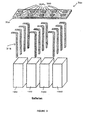
- FIG 3 is an exploded perspective view of a battery thermal management solution according to one embodiment.
- Batteries 1000 may be cooled passively by a battery cooling assembly 300 comprising heat pipes 310 and thermoelectric modules 320 mounted on a support plate 330.
- heat pipes 310 are arranged to fit between and adjacent to batteries 1000. Those heat pipes may directly contact the batteries thereby removing a heat load from the batteries. Heat load is transported via heat pipes 310 to the thermoelectric modules 320 mounted on support plate 330. It will be appreciated that heat pipes 310 are also mounted on support plate 330, but that the exploded perspective view of Figure 3 is such that the connection is not shown.
- thermoelectric modules may be connected to a voltage source and that temperature sensors may be provided on the batteries and connected into a feedback electronic loop also connected to the thermoelectric modules to ensure that battery temperature is maintained at a substantially constant value.
- a heat sink may be provided attached to the thermoelectric module and support plate such that heat loads from the thermoelectric module can be dissipated to ambient air. Such an assembly can act to cool batteries if the outside temperature is high and heat batteries if the ambient temperature is determined to be too low.
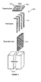
- FIG 4 is an exploded perspective view of a battery cooling assembly according to a further embodiment.
- Battery cooling assembly 400 comprises generally heat pipes 410, thermoelectric modules 420 supported on a support plate 430 and spreader plates 440.
- spreader plates 440 are placed between and in contact with batteries 1000.
- Those spreader plates are made from a thermally conductive material and act to remove heat load from the batteries and spread that heat load evenly across the spreader plates.
- Heat pipes 410 are sandwiched within the spreader plates and are operable to transfer heat load from the spreader plates to the thermoelectric modules above.
- the thermoelectric module generates a cold side temperature that causes heat at the thermoelectric module side of each heat pipe to condense, thus releasing its heat energy and controlling the temperature of the batteries 1000.
- Heat load from the thermoelectric modules may be dissipated to the air by means of a heat sink (not shown).
- a heat sink (not shown).
- Such an embodiment may act to cool batteries if outside temperature is high, and heat batteries if outside temperature is low, by provision of a feedback circuit and appropriate monitoring sensors provided at batteries and/or in the region of thermoelectric modules 420. It will be appreciated that provision of the spreader plates allows for an increased surface area for heat transfer from and to batteries 1000.
- FIG. 5 is an exploded perspective view of a battery cooling assembly according to a further embodiment.
- the battery cooling assembly 500 comprises spreader plates 540, heat pipes 510 and thermoelectric modules 520 mounted on a support plate 530.
- the embodiment shown in Figure 5 is modular and flexible and thus offers robustness to many variations of battery deployment in the field.
- the spreader plates which are thermally conductive and, for example, made of metal, may be placed between and in contact with batteries 1000. Those spreader plates are operable to remove heat load from batteries and spread that heat load across the spreader plates.
- Heat pipes 510 are then sandwiched between the spreader plates and are operable to transfer heat load from those spreader plates 540 to the thermoelectric modules provided on support plate 530.
- thermoelectric modules are provided on the top of batteries, they could also be provided on a front plate, arranged to slot between adjacent batteries horizontally rather than vertically.
- thermoelectric module is operable to generate a cold side temperature that causes the heat at the thermoelectric module side of heat pipes to condense, thus giving off its heat. In such a way, the temperature of the batteries may be controlled.
- the heat load from each thermoelectric module may be dissipated to the air via a heat sink (not shown in the Figure for clarity).
- FIG. 6 is an exploded perspective view of a battery cooling assembly according to a further embodiment.
- Battery cooling assembly 600 comprises thermoelectric modules 620, heat pipes 610 and a heat sink 660.
- thermoelectric modules 620 are arranged between batteries 1000. Heat spreaders are provided that have been removed from Figure 6 for clarity. In the solution shown in Figure 6 , thermoelectric modules are provided such that their cold side contacts spreader plates, thereby cooling them. Those spreader plates transfer the cold temperature to the batteries and thereby act to regulate temperature of the batteries.
- One particular benefit of an arrangement according to Figure 6 is that a hot side of a thermoelectric module is provided in direct contact with heat pipes 610, thereby improving efficiency of heat pipe operation to transport heat. Heat transferred by heat pipes 610 from the batteries via thermoelectric modules 620 is dissipated to the air via heat sink 660.
- the embodiments shown in Figure 6 may provide good temperature control at a hot surface of batteries 1000. It will be appreciated that the embodiment of Figure 6 offers a means of temperature control rather than significant heat dissipation.
- Heat pipes 610 are operable to control the temperature of batteries 1000. The heat load from each thermoelectric module hot side is dissipated to the ambient air via a condenser section of heat pipes 610.
- thermoelectric modules relate to generally passive systems which have no moving parts and thus offer a low maintenance or no maintenance cooling solution for batteries deployed in an industrial environment.
- Modular solutions such as those shown in Figures 5 and 6 offer a relative plug-and-play capability and the ability to retro fit to existing battery deployments.
- Heat pipes at thermoelectric modules offer large heat transfer capability and an opportunity for good thermal uniformity whilst only using a low parasitic power as a result of low power requirements of thermoelectric modules.
- Embodiments reduce the possibility of thermal runaway and are operable to heat batteries in reduced ambient conditions, thereby offering temperature stabilization apparatus. Furthermore, in contrast to known solutions, batteries are not enclosed and thus degassing of battery housing is no longer an issue. Embodiments provide a natural thermal isolation without the need for physical isolation.
Landscapes
- Engineering & Computer Science (AREA)
- Manufacturing & Machinery (AREA)
- Chemical & Material Sciences (AREA)
- Chemical Kinetics & Catalysis (AREA)
- Electrochemistry (AREA)
- General Chemical & Material Sciences (AREA)
- Physics & Mathematics (AREA)
- Electromagnetism (AREA)
- Secondary Cells (AREA)
Abstract
Description
- The present invention relates to a battery thermal management device.
- It will be appreciated that batteries have an optimum operating temperature. Batteries are often deployed in industrial environments comprising further electronic components which may serve to heat or cool an ambient environment surrounding batteries and those components. Operation of batteries within a preferred temperature window; for example, 20-25°C, may assist with long term maintenance of battery performance and efficiency, and ensures that stated battery design lifetime can be met. Operating batteries above or below a battery manufacturer approved range may reduce operational efficiency and may significantly reduce the lifespan of such a battery, leading to equipment failure and potentially significant maintenance costs.
- It is desired to provide a means of addressing issues with known battery thermal management apparatus.
- Accordingly, a first aspect provides a battery thermal management device comprising: a thermally conductive structure coupleable to a battery and operable to provide a thermal path between the battery and a thermoelectric module; the thermoelectric module being operable to transfer heat between itself and the thermally conductive structure to maintain temperature of the battery within a predetermined range.
- One possible solution to optimizing operating temperature of batteries is to provide the batteries with their own enclosure, thus separating the batteries from the surrounding environment. That physical separation of batteries from the surrounding environment, whilst having advantages, also has associated difficulties. In such an arrangement, for example, a thermoelectric module (for example, a thermoelectric cooler), may be employed to cool air within the enclosure. The thermoelectric cooler cools air in direct contact with a cold plate and a fan is employed to push that air around batteries within the enclosure. Enclosing batteries may, however, be dangerous, since natural degassing processes are hindered. If the natural degassing process is overly hindered and insufficient ventilation is provided, hydrogen may accumulate around the batteries and pose severe health and safety issues. In a worst case scenario, that build-up of hydrogen may lead to explosions if exposed to an ignition source.
- Use of air as a cooling medium in such solutions may be particularly inefficient and the pushing of that cool air over batteries within an enclosure typically occurs by use of fans. Fans inevitably have moving parts and tend to be unreliable, particularly when exposed to elevated temperatures. The failure of cooling solutions involving movement of cold air via fans is thus likely and maintenance and repair of such solutions can prove costly.
- Furthermore, it will be appreciated that encased batteries may be particularly large, dependent upon the battery application, and installation and maintenance costs for large industrial sites for use in the event of power failures can be particularly large.
- In large industrial deployments batteries may be provided in an area which is also provided with various electronic and other equipment. Components of that equipment typically each have an optimum working temperature. For example, in a telecommunications base station, general cooling of an equipment area may occur either by arrangement of appropriate air entry and exit points, associated with appropriate fans, and/or by use of appropriate air conditioning. Within an area provided with various telecommunications equipment and batteries, batteries may have an maximum operational temperature in the region of 28°C as, for example, dictated by a manufacturer, whereas telecoms electronic equipment may successfully operate at a higher temperature. Provision of a separate housing for batteries or any equipment operating at a significantly different temperature may be considered to offer a solution which can negate the need for provision of constant air conditioning, thereby saving a degree of electrical consumption within such an industrial equipment environment.
- in overview, the first aspect allows for removal of an external housing or enclosure and negates a need to use fans. Such active components are replaced with predominantly passive components such as heat pipes and thermoelectric modules as described in more detail with reference to further embodiments, to provide a battery cooling and heating solution thus offering thermal stabilisation to battery operation in an industrial battery deployment. It is believed that embodiments offer a solution which can be inexpensive, lightweight, reliable and which may be retro fitted to battery deployments in industrial environments. Although described in relation to macro batteries, for example, those used in industrial back up power plants, it will be appreciated that concepts and principles described may be used in consumer battery scenarios as appropriate. It will be appreciated that the first aspect may provide a thermal management to macro batteries, the rechargeable batteries, and to consumer batteries. Those batteries may, for example, be lead acid batteries, lithium ion batteries, or any batteries having similar characteristics.
- The first aspect provides, with appropriate choice of components, a means of providing a substantially passive means of heat extraction and heat transfer, thereby reducing power consumption expended in comparison to an active thermal management solution. It will be appreciated that the supply of power to thermoelectric modules may be considered an active step, but that the heat transfer is substantially passive.
- According to one embodiment, the thermally conductive structure is arrangeable adjacent to at least a part of a surface of the battery. Accordingly, by arranging the thermally conductive structure adjacent to at least a part, or substantially the entire surface of a battery, heat transfer can be directed to precisely where it is required, ensuring that operation of the battery is optimised.
- According to one embodiment, the thermally conducive structure is coupleable to the battery via a thermally conductive paste. Accordingly, it will be appreciated that the structure may be thermally coupled to the battery in a number of ways. There may be a direct physical connection, it may be placed adjacent to the surface, or may be affixed by means of a thermally conductive paste, direct contact, or other similar means. In each case thermal transfer between the battery and structure may be optimised.
- According to one embodiment, the thermally conductive structure is operable to spread thermal load across at least part of a surface of the battery. Accordingly, by spreading thermal load across at least a portion of a battery surface, thermal management of the battery may be more efficiently implemented, since heat transfer may be effected across a greater surface area. Accordingly, a greater battery temperature stability may be achieved. The structure may, in some embodiments, be a heat spreader. According to one embodiment, the thermally conductive structure comprises at least one thermally conductive plate arranged adjacent to at least a part of a surface of the battery. That thermally conductive plate may comprise a substantially planar metallic sheet. According to further embodiments, heat pipes or shunts may be appropriately dimensioned to negate a need for a separate heat spreader plate. That is to say, heat pipes may be placed in contact with at least a part of the surface of the battery for heat load transfer.
- According to one embodiment, the thermally conductive plate is coupled to the thermoelectric module. By directly coupling or connecting a heat spreader to a thermoelectric module, thermal stability of batteries may be more efficiently implemented. According to one embodiment, the coupling between the thermally conductive plate and the thermoelectric module comprises a direct connection. It will be appreciated that according to some embodiments connections and thermal coupling may be made between components using thermally conductive paste or similar.
- According to one embodiment, the coupling between the thermally conductive plate and the thermoelectric module comprises at least one heat pipe operable to provide a heat path between the conductive plate and the thermoelectric module. Use of heat pipes provides an efficient passive means of transferring heat within a temperature management device.
- According to one embodiment, the thermally conductive structure comprises at least one heat pipe which provides the thermal path between the battery and the thermoelectric module.
- According to one embodiment, a heat sink is coupled with the thermoelectric module and operable to dissipate heat. Accordingly, heat dissipation from the device may bye optimised.
- According to one embodiment, the coupling between the heat sink and the thermoelectric module comprises a heat shunt or pipe operable to provide a thermal path between the thermoelectric module and the heat sink.
- According to one embodiment, the device comprises a retrofit module for installation between adjacent batteries. Provision of a modular device allows implementation of a thermal management solution which is flexible across battery deployments.
- According to one embodiment, the device is integrally formed with at least one battery. Accordingly, a battery or batteries may be manufactured to include a device according to embodiments.
- According to one embodiment, the device further comprises feedback control logic, operable to monitor battery temperature and compare that temperature with said predetermined range. If it is determined that the battery temperature lies outside said predetermined range, operational temperature of the thermoelectric module may be adjusted according to a predetermined increment. The effect of that incremental change may be monitored to see whether further temperature changes are required to stabilise the battery operating temperature within the predetermined range. According to some embodiments, ambient environment temperature may be monitored and taken into account in the feedback logic unit. Furthermore, in an industrial deployment, it will be appreciated that the battery feedback thermal monitoring unit may form part of a larger industrial thermal control unit.
- A second aspect provides a method of thermally managing a battery comprising: providing a thermally conductive structure coupleable to a battery and operable to provide a thermal path between the battery and a thermoelectric module; providing a thermoelectric module arranged to transfer heat between itself and the thermally conductive structure to maintain termperature of the battery within a predetermined range.
- According to one embodiment, the thermally conductive structure is arranged adjacent to at least a part of a surface of the battery.
- According to one embodiment, the thermally conducive structure is coupled to the battery via a thermally conductive paste.
- According to one embodiment, the thermally conductive structure is arranged to spread heat load across at least part of a surface of the battery.
- According to one embodiment, the thermally conductive structure comprises at least one thermally conductive plate arranged adjacent to at least a part of a surface of the battery.
- According to one embodiment, the thermally conductive plate is coupled to the thermoelectric module.
- According to one embodiment, the coupling between the thermally conductive plate and the thermoelectric module comprises a direct connection.
- According to one embodiment, the coupling between the thermally conductive plate and the thermoelectric module comprises at least one heat pipe arranged to provide a heat path between the conductive plate and the thermoelectric module.
- According to one embodiment, the thermally conductive structure comprises at least one heat pipe arranged to provide the thermal path between the battery and the thermoelectric module.
- According to one embodiment, the method comprises coupling a heat sink with the thermoelectric module and operable to dissipate heat.
- According to one embodiment, the coupling between the heat sink and the thermoelectric module comprises a heat shunt or pipe arranged to provide a thermal path between the thermoelectric module and the heat sink.
- According to one embodiment, the method comprises retrofitting the device as a module between adjacent batteries.
- According to one embodiment, the method comprises integrally forming the device with at least one battery.
- Further particular and preferred aspects of the present invention are set out in the accompanying independent and dependent claims. Features of the dependent claims may be combined with features of the independent claims as appropriate, and in combinations other than those explicitly set out in the claims.
- Embodiments of the present invention will now be described further, with reference to the accompanying drawings, in which:
-
Figure 1 illustrates schematically main components of a heat pipe for use in embodiments; -
Figure 2 illustrates schematically main components of a thermoelectric module for use in embodiments; -
Figure 3 is an exploded perspective view of a battery temperature management solution according to one embodiment; -
Figure 4 is an exploded perspective view of a battery temperature management solution according to one embodiment; -
Figure 5 is an exploded perspective view of a battery temperature management solution according to one embodiment; and -
Figure 6 is an exploded perspective view of a battery temperature management solution according to one embodiment. - In overview, embodiments provide a battery temperature management assembly which does not require a physical enclosure surrounding batteries, and does not require use of fans to move air around batteries or to remove heat from a heat sink. Embodiments provide a passive heat management system comprising heat pipes and thermoelectric modules, thereby providing an inexpensive, lightweight, reliable and potentially modular heat management assembly which may be retro fitted to existing battery deployments.
- It will be appreciated that batteries have an optimum operating temperature. Batteries are often deployed in industrial environments comprising further electronic components which may serve to heat or cool an ambient environment surrounding batteries and those components. Operation of batteries within a preferred temperature window; for example, 20-25°C, may assist with long term maintenance of battery performance and efficiency, and ensures that stated battery design lifetime can be met. Operating batteries significantly above or below a predetermined optimum temperature; for example, 25°C, may significantly reduce the lifespan of such a battery, leading to equipment failure and potentially significant maintenance costs.
- Embodiments described herein predominantly use passive components such as heat pipes and thermoelectric modules to provide a battery cooling and/or heating solution. The use of passive components may be less expensive, weigh less and be more reliable than solutions relying on external battery housing. Passive component systems may also negate a need for use of fans or air conditioning to provide temperature stabilisation to battery units. Moreover, a passive component system may also be retro fitted to battery deployments in industrial environments.
- Before discussing the assembly in detail, an explanation will first be given of some of the main components of the assembly.
-
Figure 1 illustrates schematically an example of a heat pipe which transports and transfers heat from a heat source. The heat pipe 1 comprises acasing 10 which surrounds awick 20 which in turn, surrounds avapour cavity 30. - A heat pipe thermal cycle occurs as follows: At point A at a high temperature, working fluid evaporates to vapour, thus absorbing thermal energy. At point B the vapour migrates along the
vapour cavity 30 towards a lower temperature end. There is a temperature gradient in the direction of arrow E inFigure 1 . At point C in the heat pipe thermal cycle, vapour condenses back to a fluid and is absorbed bywick 20, thereby releasing thermal energy. As indicated by arrows at point D, the working fluid then flows back towards the high temperature end. It will be appreciated that heat pipes efficiently transfer heat energy from regions of heat to a region of cooler temperature without the requirement to actively pump or move the working fluid. Vapour condenses releasing thermal energy and is then absorbed by thewick structure 20, and can return to the evaporative end of the heat pipe structure. -
Figure 2 illustrates schematically an arrangement of athermoelectric module 100. The structure of the thermoelectric module (TEM) 100 is such that it includes n-dopedpellets 110 and p-dopedpellets 120.Pellets electrodes pellets electrodes lower substrates thermoelectric module 100 is placed in thermal contact, and to provide mechanical strength. Thesubstrates - The efficiency of heat transfer by the thermoelectric module decreases with increasing heat flux across the
pellets substrates plate 150 is the cold side and absorbs heat, andplate 160 is the hot side and releases heat. That is to say, the thermoelectric module can act as a heat pump. - A thermoelectric module such as that illustrated in
Figure 2 can provide controlled heating or cooling on the condenser or evaporator end of a heat pipe such as that illustrated inFigure 1 . It will be appreciated that low power loads, compared to those loads used to drive fans or electric air conditioning units, can be required to drive the thermoelectric module ofFigure 2 since a temperature difference of only a few degrees between ends of a heat pipe can allow efficient heat pipe operation. -
Figure 3 is an exploded perspective view of a battery thermal management solution according to one embodiment.Batteries 1000 may be cooled passively by abattery cooling assembly 300 comprisingheat pipes 310 andthermoelectric modules 320 mounted on asupport plate 330. According to the embodiment shown inFigure 3 ,heat pipes 310 are arranged to fit between and adjacent tobatteries 1000. Those heat pipes may directly contact the batteries thereby removing a heat load from the batteries. Heat load is transported viaheat pipes 310 to thethermoelectric modules 320 mounted onsupport plate 330. It will be appreciated thatheat pipes 310 are also mounted onsupport plate 330, but that the exploded perspective view ofFigure 3 is such that the connection is not shown. - Such a battery cooling solution may provide both heating and cooling of
batteries 1000 at a relatively low power cost. The cooling offered by coolingassembly 300 is substantially passive. It will be appreciated that the thermoelectric modules may be connected to a voltage source and that temperature sensors may be provided on the batteries and connected into a feedback electronic loop also connected to the thermoelectric modules to ensure that battery temperature is maintained at a substantially constant value. Furthermore, it will be appreciated that a heat sink may be provided attached to the thermoelectric module and support plate such that heat loads from the thermoelectric module can be dissipated to ambient air. Such an assembly can act to cool batteries if the outside temperature is high and heat batteries if the ambient temperature is determined to be too low. -
Figure 4 is an exploded perspective view of a battery cooling assembly according to a further embodiment.Battery cooling assembly 400 comprises generally heatpipes 410,thermoelectric modules 420 supported on asupport plate 430 andspreader plates 440. In the embodiment shown inFigure 4 ,spreader plates 440 are placed between and in contact withbatteries 1000. Those spreader plates are made from a thermally conductive material and act to remove heat load from the batteries and spread that heat load evenly across the spreader plates.Heat pipes 410 are sandwiched within the spreader plates and are operable to transfer heat load from the spreader plates to the thermoelectric modules above. The thermoelectric module generates a cold side temperature that causes heat at the thermoelectric module side of each heat pipe to condense, thus releasing its heat energy and controlling the temperature of thebatteries 1000. Heat load from the thermoelectric modules may be dissipated to the air by means of a heat sink (not shown). Such an embodiment may act to cool batteries if outside temperature is high, and heat batteries if outside temperature is low, by provision of a feedback circuit and appropriate monitoring sensors provided at batteries and/or in the region ofthermoelectric modules 420. It will be appreciated that provision of the spreader plates allows for an increased surface area for heat transfer from and tobatteries 1000. -
Figure 5 is an exploded perspective view of a battery cooling assembly according to a further embodiment. Thebattery cooling assembly 500 comprisesspreader plates 540,heat pipes 510 andthermoelectric modules 520 mounted on asupport plate 530. The embodiment shown inFigure 5 is modular and flexible and thus offers robustness to many variations of battery deployment in the field. Again, the basic idea is that the spreader plates, which are thermally conductive and, for example, made of metal, may be placed between and in contact withbatteries 1000. Those spreader plates are operable to remove heat load from batteries and spread that heat load across the spreader plates.Heat pipes 510 are then sandwiched between the spreader plates and are operable to transfer heat load from thosespreader plates 540 to the thermoelectric modules provided onsupport plate 530. - It will be appreciated that although
Figure 5 shows deployment such that the thermoelectric modules are provided on the top of batteries, they could also be provided on a front plate, arranged to slot between adjacent batteries horizontally rather than vertically. - As described previously, the thermoelectric module is operable to generate a cold side temperature that causes the heat at the thermoelectric module side of heat pipes to condense, thus giving off its heat. In such a way, the temperature of the batteries may be controlled. The heat load from each thermoelectric module may be dissipated to the air via a heat sink (not shown in the Figure for clarity).
-
Figure 6 is an exploded perspective view of a battery cooling assembly according to a further embodiment.Battery cooling assembly 600 comprisesthermoelectric modules 620,heat pipes 610 and aheat sink 660. In this embodiment,thermoelectric modules 620 are arranged betweenbatteries 1000. Heat spreaders are provided that have been removed fromFigure 6 for clarity. In the solution shown inFigure 6 , thermoelectric modules are provided such that their cold side contacts spreader plates, thereby cooling them. Those spreader plates transfer the cold temperature to the batteries and thereby act to regulate temperature of the batteries. One particular benefit of an arrangement according toFigure 6 is that a hot side of a thermoelectric module is provided in direct contact withheat pipes 610, thereby improving efficiency of heat pipe operation to transport heat. Heat transferred byheat pipes 610 from the batteries viathermoelectric modules 620 is dissipated to the air viaheat sink 660. - The embodiments shown in
Figure 6 may provide good temperature control at a hot surface ofbatteries 1000. It will be appreciated that the embodiment ofFigure 6 offers a means of temperature control rather than significant heat dissipation.Heat pipes 610 are operable to control the temperature ofbatteries 1000. The heat load from each thermoelectric module hot side is dissipated to the ambient air via a condenser section ofheat pipes 610. - It will be appreciated that the embodiment illustrated in
Figure 6 may also operate to heat the batteries, as has been described previously in relation to other embodiments. - It will be appreciated that embodiments described relate to generally passive systems which have no moving parts and thus offer a low maintenance or no maintenance cooling solution for batteries deployed in an industrial environment. Modular solutions such as those shown in
Figures 5 and6 offer a relative plug-and-play capability and the ability to retro fit to existing battery deployments. Heat pipes at thermoelectric modules offer large heat transfer capability and an opportunity for good thermal uniformity whilst only using a low parasitic power as a result of low power requirements of thermoelectric modules. - Embodiments reduce the possibility of thermal runaway and are operable to heat batteries in reduced ambient conditions, thereby offering temperature stabilization apparatus. Furthermore, in contrast to known solutions, batteries are not enclosed and thus degassing of battery housing is no longer an issue. Embodiments provide a natural thermal isolation without the need for physical isolation.
- Although embodiments of the present invention are described as separate retro fit devices, it will be appreciated that similar embodiments can be implemented if batteries and cooling apparatus are integrally formed.
- Hence, it can be seen that an arrangement is provided in which cooling can be provided at extremely low cost in a highly reliable modular manner and which does not affect normal operation of battery deployments. Such arrangements do not significantly affect safety of batteries, or require high maintenance, unlike standard solutions which enclose the batteries thereby promoting the possibility of catastrophic failure and enabling a build-up of hydrogen.
- The description and drawings merely illustrate the principles of the invention. It will thus be appreciated that those skilled in the art will be able to devise various arrangements that, although not explicitly described or shown herein, embody the principles of the invention and are included within its scope. Furthermore, all examples recited herein are principally intended to expressly be only for pedagogical purposes to aid the reader in understanding the principles of the invention and the concepts contributed by the inventors to furthering the art, and are to be construed as being without limitation to such specifically recited examples and conditions. Moreover, all statements herein reciting principles, aspects and embodiments of the invention, as well as specific examples thereof, are intended to encompass equivalents thereof.
Claims (14)
- A battery thermal management device comprising: a thermally conductive structure coupleable to a battery and operable to provide a thermal path between said battery and a thermoelectric module;
said thermoelectric module being operable to transfer heat between itself and said thermally conductive structure to maintain temperature of said battery within a predetermined range. - A battery thermal management device according to claim 1, wherein said thermally conductive structure is arrangeable adjacent to at least a part of a surface of said battery.
- A battery thermal management device according to claim 1 or claim 2, wherein said thermally conducive structure is coupleable to said battery via a thermally conductive paste.
- A battery thermal management device according to any preceding claim, wherein said thermally conductive structure is operable to spread thermal load across at least part of a surface of said battery.
- A battery thermal management device according to any preceding claim, wherein said thermally conductive structure comprises at least one thermally conductive plate arranged adjacent to at least a part of a surface of said battery.
- A battery thermal management device according to claim 5, wherein said thermally conductive plate is coupled to said thermoelectric module.
- A battery thermal management device according to claim 6, wherein said coupling between said thermally conductive plate and said thermoelectric module comprises a direct connection.
- A battery thermal management device according to claim 7, wherein said coupling between said thermally conductive plate and said thermoelectric module comprises at least one heat pipe operable to provide a heat path between said conductive plate and said thermoelectric module.
- A battery thermal management device according to any preceding claim, wherein said thermally conductive structure comprises at least one heat pipe which provides said thermal path between said battery and said thermoelectric module.
- A battery thermal management device according to any preceding claim, comprising a heat sink coupled with said thermoelectric module and operable to dissipate heat.
- A battery thermal management device according to claim 10, wherein said coupling between said heat sink and said thermoelectric module comprises a heat shunt/pipe operable to provide a thermal path between said thermoelectric module and said heat sink.
- A battery thermal management device according to any preceding claim, comprising a retrofit module for installation between adjacent batteries.
- A battery thermal management device according to any one of claims 1 to 12, integrally formed with at least one battery.
- A method of thermally managing a battery comprising:providing a thermally conductive structure coupleable to a battery andoperable to provide a thermal path between said battery and a thermoelectric module;providing a thermoelectric module arranged to transfer heat between itself and said thermally conductive structure to maintain temperature of said battery within a predetermined range.
Priority Applications (3)
| Application Number | Priority Date | Filing Date | Title |
|---|---|---|---|
| EP20110360042 EP2565977A1 (en) | 2011-08-29 | 2011-08-29 | Battery cooling |
| PCT/EP2012/003377 WO2013029744A1 (en) | 2011-08-29 | 2012-08-07 | Battery cooling |
| US14/237,376 US20140165597A1 (en) | 2011-08-29 | 2012-08-07 | Battery cooling |
Applications Claiming Priority (1)
| Application Number | Priority Date | Filing Date | Title |
|---|---|---|---|
| EP20110360042 EP2565977A1 (en) | 2011-08-29 | 2011-08-29 | Battery cooling |
Publications (1)
| Publication Number | Publication Date |
|---|---|
| EP2565977A1 true EP2565977A1 (en) | 2013-03-06 |
Family
ID=46639435
Family Applications (1)
| Application Number | Title | Priority Date | Filing Date |
|---|---|---|---|
| EP20110360042 Withdrawn EP2565977A1 (en) | 2011-08-29 | 2011-08-29 | Battery cooling |
Country Status (3)
| Country | Link |
|---|---|
| US (1) | US20140165597A1 (en) |
| EP (1) | EP2565977A1 (en) |
| WO (1) | WO2013029744A1 (en) |
Cited By (16)
| Publication number | Priority date | Publication date | Assignee | Title |
|---|---|---|---|---|
| CN103762396A (en) * | 2014-01-02 | 2014-04-30 | 中国矿业大学 | Battery heat management system based on pulsating heat pipes |
| CN103762395A (en) * | 2014-01-02 | 2014-04-30 | 中国矿业大学 | Power battery heat management system based on metal phase-change materials |
| KR101428383B1 (en) * | 2013-04-26 | 2014-08-08 | 현대자동차주식회사 | Device for cooling battery module of vehicle |
| US20150207188A1 (en) * | 2013-12-11 | 2015-07-23 | Hyundai Motor Company | Battery for vehicle |
| WO2018222663A1 (en) * | 2017-05-30 | 2018-12-06 | General Electric Company | Modular energy storage system with battery cooling |
| DE102019100233A1 (en) | 2019-01-07 | 2019-02-28 | FEV Europe GmbH | Cooling structure for a battery |
| US10236547B2 (en) * | 2013-10-29 | 2019-03-19 | Gentherm Incorporated | Battery thermal management systems including heat spreaders with thermoelectric devices |
| US10270141B2 (en) | 2013-01-30 | 2019-04-23 | Gentherm Incorporated | Thermoelectric-based thermal management system |
| US10295309B2 (en) | 2013-07-08 | 2019-05-21 | Loukus Technologies, Inc. | Core structured components and containers |
| US10337770B2 (en) | 2011-07-11 | 2019-07-02 | Gentherm Incorporated | Thermoelectric-based thermal management of electrical devices |
| CN110085941A (en) * | 2019-04-04 | 2019-08-02 | 华南理工大学 | A kind of radiator structure for cylindrical lithium battery group |
| US10686232B2 (en) | 2013-01-14 | 2020-06-16 | Gentherm Incorporated | Thermoelectric-based thermal management of electrical devices |
| US10700393B2 (en) | 2014-09-12 | 2020-06-30 | Gentherm Incorporated | Graphite thermoelectric and/or resistive thermal management systems and methods |
| US11152557B2 (en) | 2019-02-20 | 2021-10-19 | Gentherm Incorporated | Thermoelectric module with integrated printed circuit board |
| US11264655B2 (en) | 2009-05-18 | 2022-03-01 | Gentherm Incorporated | Thermal management system including flapper valve to control fluid flow for thermoelectric device |
| US11993132B2 (en) | 2018-11-30 | 2024-05-28 | Gentherm Incorporated | Thermoelectric conditioning system and methods |
Families Citing this family (16)
| Publication number | Priority date | Publication date | Assignee | Title |
|---|---|---|---|---|
| KR101611007B1 (en) * | 2013-10-17 | 2016-04-08 | 현대자동차주식회사 | Heating and cooling cup holder |
| TWI524574B (en) * | 2013-12-31 | 2016-03-01 | 原瑞電池科技股份有限公司 | Battery module |
| CN103825067A (en) * | 2014-02-28 | 2014-05-28 | 华南理工大学 | Efficient heat radiation device for lithium ion power battery |
| GB2531260B (en) * | 2014-10-13 | 2019-08-14 | Bae Systems Plc | Peltier effect heat transfer system |
| US20170028869A1 (en) * | 2015-07-27 | 2017-02-02 | Ford Global Technologies, Llc | Thermal management system including cold plate and integrated heat pipe |
| US10892528B2 (en) | 2015-12-14 | 2021-01-12 | Lg Chem, Ltd. | Battery module, battery pack comprising battery module, and vehicle comprising battery pack |
| WO2017218218A1 (en) * | 2016-06-13 | 2017-12-21 | Pure Watercraft, Inc. | Batteries with thermal management |
| WO2018187330A1 (en) | 2017-04-03 | 2018-10-11 | Yotta Solar, Inc. | Thermally regulated modular energy storage device and methods |
| DE102017215376A1 (en) * | 2017-09-01 | 2019-03-07 | Audi Ag | Temperature control for tempering a battery and motor vehicle |
| US10873116B2 (en) * | 2018-05-18 | 2020-12-22 | Lee Fei Chen | Charging device having thermoelectric module |
| KR102425695B1 (en) * | 2019-01-31 | 2022-07-28 | 삼성에스디아이 주식회사 | Battery Pack |
| KR102377870B1 (en) * | 2019-03-04 | 2022-03-22 | 주식회사 엘지에너지솔루션 | Battery module and battery pack including the same and vehicle |
| EP3862219A1 (en) * | 2020-02-07 | 2021-08-11 | Volvo Car Corporation | Temperature management system for an energy system of a motor vehicle |
| TWI796871B (en) * | 2021-12-13 | 2023-03-21 | 光陽工業股份有限公司 | Electrothermal battery power balance module |
| US12249857B2 (en) | 2022-01-13 | 2025-03-11 | Lee Fei Chen | Electric energy management system with thermoelectric power supply conversion function |
| EP4563956A1 (en) * | 2023-11-30 | 2025-06-04 | Volvo Truck Corporation | A thermal management film for detecting and/or for regulating a temperature of an electrical device |
Citations (10)
| Publication number | Priority date | Publication date | Assignee | Title |
|---|---|---|---|---|
| US6653002B1 (en) * | 1997-05-09 | 2003-11-25 | Ronald J. Parise | Quick charge battery with thermal management |
| KR20050018518A (en) * | 2003-08-14 | 2005-02-23 | 현대자동차주식회사 | Cooling device for battery tray of electric vehicle |
| US20050257532A1 (en) * | 2004-03-11 | 2005-11-24 | Masami Ikeda | Module for cooling semiconductor device |
| US20060060236A1 (en) * | 2004-09-23 | 2006-03-23 | Kim Tae-Yong | System for controlling temperature of a secondary battery module |
| WO2008001022A1 (en) * | 2006-06-30 | 2008-01-03 | Valeo Equipements Electriques Moteur | Compact power supply device for a motor vehicle comprising cooling means provided with an external heat sink |
| JP2009152440A (en) * | 2007-12-21 | 2009-07-09 | Calsonic Kansei Corp | Temperature regulator for heating element |
| US20090263708A1 (en) * | 2008-04-02 | 2009-10-22 | Josh Bender | System and method of integrated thermal management for a multi-cell battery pack |
| DE102008054958A1 (en) * | 2008-12-19 | 2010-07-01 | Robert Bosch Gmbh | Tempering system for tempering energy storage system having electrical storage, particularly chargeable battery, of motor vehicle, has heat transport device for thermal binding of electrical storage |
| US20100243346A1 (en) * | 2009-03-27 | 2010-09-30 | Gm Global Technology Operations, Inc. | Battery pack for a vehicle |
| US20110183178A1 (en) * | 2010-01-27 | 2011-07-28 | Kwon Sohn | Battery pack |
Family Cites Families (5)
| Publication number | Priority date | Publication date | Assignee | Title |
|---|---|---|---|---|
| US4314008A (en) * | 1980-08-22 | 1982-02-02 | General Electric Company | Thermoelectric temperature stabilized battery system |
| KR101108191B1 (en) * | 2010-05-24 | 2012-02-06 | 에스비리모티브 주식회사 | Battery Pack |
| US20110300420A1 (en) * | 2010-06-02 | 2011-12-08 | Eaton Corporation | Temperature controlled battery pack assembly and methods for using the same |
| US8415041B2 (en) * | 2010-06-30 | 2013-04-09 | Nissan North America, Inc. | Vehicle battery temperature control system fluidly coupled to an air-conditioning refrigeration system |
| US8658299B2 (en) * | 2011-05-03 | 2014-02-25 | GM Global Technology Operations LLC | Battery pack thermal management system and method |
-
2011
- 2011-08-29 EP EP20110360042 patent/EP2565977A1/en not_active Withdrawn
-
2012
- 2012-08-07 WO PCT/EP2012/003377 patent/WO2013029744A1/en not_active Ceased
- 2012-08-07 US US14/237,376 patent/US20140165597A1/en not_active Abandoned
Patent Citations (10)
| Publication number | Priority date | Publication date | Assignee | Title |
|---|---|---|---|---|
| US6653002B1 (en) * | 1997-05-09 | 2003-11-25 | Ronald J. Parise | Quick charge battery with thermal management |
| KR20050018518A (en) * | 2003-08-14 | 2005-02-23 | 현대자동차주식회사 | Cooling device for battery tray of electric vehicle |
| US20050257532A1 (en) * | 2004-03-11 | 2005-11-24 | Masami Ikeda | Module for cooling semiconductor device |
| US20060060236A1 (en) * | 2004-09-23 | 2006-03-23 | Kim Tae-Yong | System for controlling temperature of a secondary battery module |
| WO2008001022A1 (en) * | 2006-06-30 | 2008-01-03 | Valeo Equipements Electriques Moteur | Compact power supply device for a motor vehicle comprising cooling means provided with an external heat sink |
| JP2009152440A (en) * | 2007-12-21 | 2009-07-09 | Calsonic Kansei Corp | Temperature regulator for heating element |
| US20090263708A1 (en) * | 2008-04-02 | 2009-10-22 | Josh Bender | System and method of integrated thermal management for a multi-cell battery pack |
| DE102008054958A1 (en) * | 2008-12-19 | 2010-07-01 | Robert Bosch Gmbh | Tempering system for tempering energy storage system having electrical storage, particularly chargeable battery, of motor vehicle, has heat transport device for thermal binding of electrical storage |
| US20100243346A1 (en) * | 2009-03-27 | 2010-09-30 | Gm Global Technology Operations, Inc. | Battery pack for a vehicle |
| US20110183178A1 (en) * | 2010-01-27 | 2011-07-28 | Kwon Sohn | Battery pack |
Cited By (22)
| Publication number | Priority date | Publication date | Assignee | Title |
|---|---|---|---|---|
| US11264655B2 (en) | 2009-05-18 | 2022-03-01 | Gentherm Incorporated | Thermal management system including flapper valve to control fluid flow for thermoelectric device |
| US10337770B2 (en) | 2011-07-11 | 2019-07-02 | Gentherm Incorporated | Thermoelectric-based thermal management of electrical devices |
| US10686232B2 (en) | 2013-01-14 | 2020-06-16 | Gentherm Incorporated | Thermoelectric-based thermal management of electrical devices |
| US10270141B2 (en) | 2013-01-30 | 2019-04-23 | Gentherm Incorporated | Thermoelectric-based thermal management system |
| US10784546B2 (en) | 2013-01-30 | 2020-09-22 | Gentherm Incorporated | Thermoelectric-based thermal management system |
| KR101428383B1 (en) * | 2013-04-26 | 2014-08-08 | 현대자동차주식회사 | Device for cooling battery module of vehicle |
| US9728825B2 (en) | 2013-04-26 | 2017-08-08 | Hyundai Motor Company | Device for indirectly cooling battery module of eco-friendly vehicle |
| US10295309B2 (en) | 2013-07-08 | 2019-05-21 | Loukus Technologies, Inc. | Core structured components and containers |
| US10236547B2 (en) * | 2013-10-29 | 2019-03-19 | Gentherm Incorporated | Battery thermal management systems including heat spreaders with thermoelectric devices |
| US20150207188A1 (en) * | 2013-12-11 | 2015-07-23 | Hyundai Motor Company | Battery for vehicle |
| CN103762395B (en) * | 2014-01-02 | 2015-12-02 | 中国矿业大学 | A kind of power battery thermal management system based on phase change materials |
| CN103762396A (en) * | 2014-01-02 | 2014-04-30 | 中国矿业大学 | Battery heat management system based on pulsating heat pipes |
| CN103762396B (en) * | 2014-01-02 | 2015-12-02 | 中国矿业大学 | A kind of battery thermal management system based on pulsating heat pipe |
| CN103762395A (en) * | 2014-01-02 | 2014-04-30 | 中国矿业大学 | Power battery heat management system based on metal phase-change materials |
| US10700393B2 (en) | 2014-09-12 | 2020-06-30 | Gentherm Incorporated | Graphite thermoelectric and/or resistive thermal management systems and methods |
| WO2018222663A1 (en) * | 2017-05-30 | 2018-12-06 | General Electric Company | Modular energy storage system with battery cooling |
| US12206080B2 (en) | 2017-05-30 | 2025-01-21 | Ge Grid Solutions Llc | Modular energy storage system with battery cooling |
| US11993132B2 (en) | 2018-11-30 | 2024-05-28 | Gentherm Incorporated | Thermoelectric conditioning system and methods |
| US12459335B2 (en) | 2018-11-30 | 2025-11-04 | Gentherm Incorporated | Thermoelectric conditioning system and methods |
| DE102019100233A1 (en) | 2019-01-07 | 2019-02-28 | FEV Europe GmbH | Cooling structure for a battery |
| US11152557B2 (en) | 2019-02-20 | 2021-10-19 | Gentherm Incorporated | Thermoelectric module with integrated printed circuit board |
| CN110085941A (en) * | 2019-04-04 | 2019-08-02 | 华南理工大学 | A kind of radiator structure for cylindrical lithium battery group |
Also Published As
| Publication number | Publication date |
|---|---|
| WO2013029744A1 (en) | 2013-03-07 |
| US20140165597A1 (en) | 2014-06-19 |
Similar Documents
| Publication | Publication Date | Title |
|---|---|---|
| EP2565977A1 (en) | Battery cooling | |
| WO2014131460A1 (en) | Cooling heat generating components | |
| CN1115090C (en) | Base station heat management system | |
| CN109952002B (en) | Cooling and heat dissipation box body and heat dissipation control method | |
| JP6637765B2 (en) | Thermoelectric based thermal management system | |
| US7272002B2 (en) | Auxiliary cooling methods and systems for electrical device housings | |
| US20190140327A1 (en) | Power storage device | |
| US20100266885A1 (en) | Battery cooling apparatus | |
| JP6861234B2 (en) | Liquid cooling with outdoor cooler rack system | |
| EP3396801B1 (en) | High voltage terminal cooling structure | |
| JP2012160338A (en) | Battery module | |
| TWI531103B (en) | Battery power supply with multiple battery modules | |
| KR20130104165A (en) | Battery cooling system using thermoelectric module | |
| US12494529B2 (en) | Receiving device for receiving and cooling insertion modules | |
| US20180269371A1 (en) | Cooling Arrangement For An Electronic Component | |
| US11990741B2 (en) | Device for cooling a bus bar | |
| CN116744546B (en) | Superconductive heat dissipation battery protection board | |
| US9018511B2 (en) | Spring-loaded heat exchanger fins | |
| WO2013123970A1 (en) | Cooling system and method for cooling a heat generating unit | |
| JP2018054499A (en) | Load device and load application method | |
| EP3396288A1 (en) | Refrigeration device for a power converter | |
| EP3206470A1 (en) | Frame for holding an electronic board, housing, and rack including frame and housing | |
| FI20175889A1 (en) | Thermal management system for an electrical power source | |
| US20190363410A1 (en) | Externally-cooled battery housing | |
| CN224178492U (en) | Battery management device and energy storage equipment |
Legal Events
| Date | Code | Title | Description |
|---|---|---|---|
| PUAI | Public reference made under article 153(3) epc to a published international application that has entered the european phase |
Free format text: ORIGINAL CODE: 0009012 |
|
| AK | Designated contracting states |
Kind code of ref document: A1 Designated state(s): AL AT BE BG CH CY CZ DE DK EE ES FI FR GB GR HR HU IE IS IT LI LT LU LV MC MK MT NL NO PL PT RO RS SE SI SK SM TR |
|
| AX | Request for extension of the european patent |
Extension state: BA ME |
|
| 111Z | Information provided on other rights and legal means of execution |
Free format text: AL AT BE BG CH CY CZ DE DK EE ES FI FR GB GR HR HU IE IS IT LI LT LU LV MC MK MT NL NO PL PT RO RS SE SI SK SM TR Effective date: 20130410 |
|
| 17P | Request for examination filed |
Effective date: 20130906 |
|
| RBV | Designated contracting states (corrected) |
Designated state(s): AL AT BE BG CH CY CZ DE DK EE ES FI FR GB GR HR HU IE IS IT LI LT LU LV MC MK MT NL NO PL PT RO RS SE SI SK SM TR |
|
| RAP1 | Party data changed (applicant data changed or rights of an application transferred) |
Owner name: ALCATEL LUCENT |
|
| D11X | Information provided on other rights and legal means of execution (deleted) | ||
| 17Q | First examination report despatched |
Effective date: 20160317 |
|
| RAP1 | Party data changed (applicant data changed or rights of an application transferred) |
Owner name: ALCATEL LUCENT |
|
| STAA | Information on the status of an ep patent application or granted ep patent |
Free format text: STATUS: EXAMINATION IS IN PROGRESS |
|
| STAA | Information on the status of an ep patent application or granted ep patent |
Free format text: STATUS: THE APPLICATION IS DEEMED TO BE WITHDRAWN |
|
| 18D | Application deemed to be withdrawn |
Effective date: 20210526 |