EP2565884A2 - High voltage coil - Google Patents
High voltage coil Download PDFInfo
- Publication number
- EP2565884A2 EP2565884A2 EP12460050A EP12460050A EP2565884A2 EP 2565884 A2 EP2565884 A2 EP 2565884A2 EP 12460050 A EP12460050 A EP 12460050A EP 12460050 A EP12460050 A EP 12460050A EP 2565884 A2 EP2565884 A2 EP 2565884A2
- Authority
- EP
- European Patent Office
- Prior art keywords
- coil
- voltage
- screen
- external
- transformer
- Prior art date
- Legal status (The legal status is an assumption and is not a legal conclusion. Google has not performed a legal analysis and makes no representation as to the accuracy of the status listed.)
- Granted
Links
Images




Classifications
-
- H—ELECTRICITY
- H01—ELECTRIC ELEMENTS
- H01F—MAGNETS; INDUCTANCES; TRANSFORMERS; SELECTION OF MATERIALS FOR THEIR MAGNETIC PROPERTIES
- H01F27/00—Details of transformers or inductances, in general
- H01F27/34—Special means for preventing or reducing unwanted electric or magnetic effects, e.g. no-load losses, reactive currents, harmonics, oscillations, leakage fields
- H01F27/36—Electric or magnetic shields or screens
- H01F27/363—Electric or magnetic shields or screens made of electrically conductive material
-
- H—ELECTRICITY
- H01—ELECTRIC ELEMENTS
- H01F—MAGNETS; INDUCTANCES; TRANSFORMERS; SELECTION OF MATERIALS FOR THEIR MAGNETIC PROPERTIES
- H01F38/00—Adaptations of transformers or inductances for specific applications or functions
- H01F38/20—Instruments transformers
- H01F38/22—Instruments transformers for single phase AC
- H01F38/24—Voltage transformers
- H01F38/26—Constructions
-
- H—ELECTRICITY
- H01—ELECTRIC ELEMENTS
- H01F—MAGNETS; INDUCTANCES; TRANSFORMERS; SELECTION OF MATERIALS FOR THEIR MAGNETIC PROPERTIES
- H01F27/00—Details of transformers or inductances, in general
- H01F27/34—Special means for preventing or reducing unwanted electric or magnetic effects, e.g. no-load losses, reactive currents, harmonics, oscillations, leakage fields
- H01F27/36—Electric or magnetic shields or screens
-
- H—ELECTRICITY
- H01—ELECTRIC ELEMENTS
- H01F—MAGNETS; INDUCTANCES; TRANSFORMERS; SELECTION OF MATERIALS FOR THEIR MAGNETIC PROPERTIES
- H01F38/00—Adaptations of transformers or inductances for specific applications or functions
- H01F38/20—Instruments transformers
- H01F38/22—Instruments transformers for single phase AC
- H01F38/28—Current transformers
- H01F38/30—Constructions
- H01F2038/305—Constructions with toroidal magnetic core
-
- H—ELECTRICITY
- H01—ELECTRIC ELEMENTS
- H01F—MAGNETS; INDUCTANCES; TRANSFORMERS; SELECTION OF MATERIALS FOR THEIR MAGNETIC PROPERTIES
- H01F38/00—Adaptations of transformers or inductances for specific applications or functions
- H01F38/20—Instruments transformers
- H01F38/22—Instruments transformers for single phase AC
- H01F38/34—Combined voltage and current transformers
Definitions
- the invention deals with a high voltage voltage coil which is an element of a voltage transformer used in a combined instrument transformer which comprises of a current transformer and a voltage transformer located in a common enclosure.
- a combined instrument transformer is applicable in high voltage electric power measuring systems.
- a combined instrument transformer known from patent description PL193711 comprises an inductive toroidal core type current transformer and an inductive three-leg core type potential transformer, located in the upper and lower parts of the combined instrument transformer, respectively, in metal enclosures and it has an insulator filled with insulating medium in which equipotential screens of an electrically conductive material are located.
- the primary winding of the voltage transformer and the secondary winding of the voltage transformer are wound on a cylindrical tube of an insulating material, located on the central column of the core which is a composition of two rectangular cores.
- the equipotential screens are built into an insulating material spread over the high voltage output lead of the voltage transformer and they are connected with the equipotential screens built into the insulating material spread over the tube with the output leads of the secondary windings of the current transformer.
- the insulating medium is located in the space between the insulated windings of the current and voltage transformers and their metal enclosures as well as in the space between the insulated input leads of the windings of the transformers running along the insulator and the internal surface of the insulator.
- JUK123 made by ABB Sp.z o.o.
- the current coil of the current transformer which surrounds the current lead, is located in a metal enclosure.
- Output leads of the windings of the current coil are taken through a current bushing in the form of a metal tube to a terminal box connected to the casing of the voltage transformer.
- the current bushing is connected with the metal enclosure through a screw joint in which the external thread is made at the end of the bushing tube, and the internal thread is made in the opening of a joining sleeve which is tightly fitted in the opening made in the metal casing of the current coil.
- the screw joint of the current bushing with the joining sleeve enables the appearance of blades of the protruding thread and edges of the sleeve, which may weaken the strength of the paper-and-oil insulation at the place where bushing joins the current coil enclosure.
- the voltage transformer comprises a voltage coil in which the primary winding is wound on the secondary winding, which are wound on a cylindrical tube of an insulating material. Inside the tube there are the columns of two magnetic cores which form a jacket core system for the windings of the voltage transformer. At the bottom, the voltage transformer is closed by the bottom part of the metal casing with four openings used to fasten the transformer to the frame by means of bolts.
- the voltage coil windings are provided with an upper screen located inside the voltage coil in the shape of a cylinder and covering the final layer of the winding, made from a copper sheet with wires soldered to the edges of the sheet to avoid sharp edges.
- the output lead of the voltage coil is the high voltage bushing of the coil, which is located in an insulating material with equipotential screens made from aluminum sheets which after being wound into the insulating material form cylindrical covers situated centrically around the longitudinal axis of the voltage bushing.
- the external screen of the voltage coil was formed of aluminum foil and was connected with the final aluminum screen situated on the voltage bushing.
- an external screen made of black semiconducting paper which is located outside the voltage coil and which is electrically connected with the final, wound on the largest diameter, aluminum screen situated on the voltage bushing.
- the essence of the high voltage voltage coil comprising a magnetic core, a primary winding wound onto the secondary winding and surrounded by an upper screen to which there is fixed a bushing of a high voltage instrument transformer in the form of a conducting rod placed in insulating material in which cylindrical, axial equipotential screens are situated on different levels, the primary winding together with the upper screen being located in the coil insulation which is covered by an external screen is that the upper screen has the shape of a ring with a gap, integrated with the connecting element in the form of a truncated cone.
- the larger base of the truncated cone is situated on the external surface of the ring.
- the cone has an axial opening into which the threaded end of the rod is screwed.
- the equipotential screens are situated centrically around the conducting rod and they have overlapping longitudinal edges which do not touch one another in any point.
- a copper tape is wound on the voltage coil insulation and on the external screen of the voltage coil.
- the internal and external edges of the ring of the upper screen are rounded, and the rounding radius "R1" of the external edge is larger than the rounding radius "R2" of the internal edge.
- the upper screen is made as an aluminum cast.
- the equipotential screens of the bushing are situated in relation to the rod axis in such way that the line connecting the upper edges of the screens located in the insulating material is situated at an acute angle to the rod axis and at the same time it is parallel to the line connecting the bottom edges of these screens.
- the angle " ⁇ " of the mutual overlapping of the longitudinal edges of the equipotential screens of the bushing is less than 60°.
- the insulating material of the bushing is paper insulation whose bands are wound stepwise on the bushing rod, narrowing towards both ends of the rod.
- the final bushing screen made of conducting material is permanently connected with the copper tape on the external side outline of the voltage coil.
- the output leads of the copper tape are the end of the band in the form of copper plaiting which is permanently fixed to an insulating connector.
- the external screen of the coil which reflects the outer surface of the coil, is made of a semiconducting paper.
- the coil according any of the claims 1 through 9 is an element of a voltage transformer which together with a current transformer and an insulator make a combined instrument transformer.
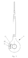
- fig. 1 shows the combined instrument transformer in half-view and in broken-out frontal half section showing the insulator in section
- fig. 2 the voltage coil in side section
- fig. 3 the voltage coil in frontal view partially broken-out
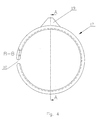
- fig. 4 - the upper screen of the voltage coil in frontal view
- fig. 5 the upper screen of the voltage coil in side view
- fig. 6 the voltage bushing with indicated equipotential screens in half-view and in half section
- fig. 7 the voltage bushing with the equipotential screens from fig. 6 in cross-section along line C-C, fig.
- the combined instrument transformer comprises a current transformer 1 and a voltage transformer 2 located in the upper and lower parts of the transformer, respectively, in metal enclosures 1a and 2a, 2b and it has an insulator 3 filled with an insulating medium 4.
- the current transformer 1 is located in a metal head 5 in which there is at least one cylindrical core 6. Secondary windings 7 of the current transformer 1 are wound on the core 6. The windings 7 with the core 6 are located in a metal enclosure 8.
- a primary winding 9 whose terminal is connected to the metal head 5 of the instrument transformer runs through the center of the cores.
- the output leads of the secondary windings 7 of the instrument transformer 1 are brought into a metal tube 10 which is a current bushing of the transformer 1, which is located inside the insulator 3.
- the output leads of the secondary windings 7 are brought outside the tube 10 at its other end and they are connected with the external terminals located in a terminal box attached to the lower part of the enclosure 2b of the voltage transformer 2, which is not shown in the drawing.
- a compensatory bellows 11 used to compensate variations in the volume of the insulating medium 4 which can be insulating oil, sulfur hexafluoride, or nitrogen.
- the voltage transformer comprises a voltage coil 12 with a primary winding 13 wound onto a secondary winding 14, which are wound on a cylindrical tube 15 of insulating material. Inside the tube 15 there are placed the columns of two magnetic cores 16 which make a jacket-core system for the windings of the voltage transformer 2.
- the windings of the coil 12 have the shape of a trapeze, which is shown in fig. 2 .
- the shorter base of the trapeze is galvanically connected with the inner surface of the upper screen 17 of the voltage coil.
- the upper screen 17 is formed in the shape of a metal ring with a gap 18 which prevents the formation of a shorted coil, and it comprises a connecting element 19 which has the shape of a truncated cone whose larger-diameter base is situated on the external surface of the ring.
- a threaded port 20 into which the threaded end of a conducting rod 21 constituting the voltage bushing of the voltage coil is screwed.
- the whole upper screen 17 is made as an aluminum casting.
- the ring edges are rounded, and the radius of the rounding of the external edge R1 is bigger than the radius of the rounding of the internal edge R2, which allows to minimize the intensity of the electric field on the edges of the screen 17.
- the connecting element 20 contains also a transverse port 22 which is used to introduce a set screw into it.
- the windings of the voltage transformer 2 with the upper screen 17 are insulated with insulating material 23 in the form of paper-and-oil insulation.
- the conducting rod 21 that is screwed into the port 20 is situated along its own length in the bushing insulation 24 in the form of paper bands wound onto the rod 21.
- equipotential screens 25 in the form of sheets of conducting material, forming cylindrical screens of equal length, with the exception of a shorter external screen, which are situated parallel to one another and to the axis of the rod 22.
- the line joining the upper edges of the equipotential screens, with the exception of the external screen which is shorter than the other screens, is situated at an acute angle to the axis of the rod 21 and at the same time parallel to the line connecting the bottom edges of the equipotential screens.
- the longitudinal edges of the equipotential screens overlap one another, which is shown in fig. 7 , but these edges do not touch because there is a layer of a thickness of one insulation paper sheet between the overlapping screen layers.
- the angle ⁇ at which the edges of the screens overlap should not exceed 60°, and preferably it should be within the range of 15-45°.
- the presented system of cylindrical equipotential screens 25, made of aluminum foil, and their mutual position in the paper insulation 24 enable the achievement of considerable homogeneity of the electric field in the voltage bushing of the voltage coil, which greatly improves the quality of the combined instrument transformer.
- the insulation of the bushing 24 is gradated on both sides, i.e. the upper and the lower sides, and it is connected with the insulation material 23 of the voltage coil forming the main insulation of the voltage transformer 2, in which the lower gradated side of the insulation 24 is comprised.
- an external screen 26 of a shape reflecting the coil surface.
- a conducting copper tape 27 is evenly wound onto the external screen 26, which is shown in fig. 8, 9 , 10 and 11 .
- the tape 27 twists around the front surfaces of the coil and covers the outer side outline of the coil, the sections of the band that intersect on the side outline of the coil being permanently joined with one another e.g. by soldering.
- One end of the band 27 is taken outside the insulation and it is fixed to the insulating connector 28, to which also the end of the band 29 in the form of a copper plaiting, constituting the conducting outlet of the external screen 26, is fixed.
- the final, shorter screen 25 of the conducting material is permanently connected with the copper tape 27, which is not shown in the drawing.
- pressboard disks 30 through which the band is threaded are fixed to both sides of the voltage coil.
- the function of the copper tape 27 is to conduct an electric charge to earth and to equalize potentials on the voltage coil.
- the use of the copper tape 27 permits an even distribution of the potential on the voltage coil.
- the combined instrument transformer is closed by the lower part of the casing 2b with four openings used to fix the transformer to the frame by means of bolts, not shown in the drawing.
- the equipotential screens 25 built into the insulation 24 surrounding the conducting rod 21 of the voltage transformer are not galvanically connected.
- the design and shape of the upper screen 17 located in the voltage coil 12 in the paper-and-oil insulation 23, as well as the way of connecting it with the voltage bushing wound on the metal rod 21 where the thread of the metal rod 21 is completely hidden in the connecting element 19, and the shape of the primary winding of the voltage transformer 13 ensure the optimum distribution of the electric field.
- the upper screen 17 functions as a support structure for the bushing of the voltage coil.
- the threaded connection can be a metric thread, a unified screw thread, or any other thread depending on the design needs.
- the system of the screens 25 of a design in which the longer sides of the screens overlap ensures an even distribution of voltage gradients at the ends of the screens.
Landscapes
- Engineering & Computer Science (AREA)
- Power Engineering (AREA)
- Transformers For Measuring Instruments (AREA)
Abstract
Description
- The invention deals with a high voltage voltage coil which is an element of a voltage transformer used in a combined instrument transformer which comprises of a current transformer and a voltage transformer located in a common enclosure. A combined instrument transformer is applicable in high voltage electric power measuring systems.
- A combined instrument transformer known from patent description
PL193711 - There is known a combined instrument transformer of a similar design, JUK123 made by ABB Sp.z o.o., in which the current coil of the current transformer, which surrounds the current lead, is located in a metal enclosure. Output leads of the windings of the current coil are taken through a current bushing in the form of a metal tube to a terminal box connected to the casing of the voltage transformer. The current bushing is connected with the metal enclosure through a screw joint in which the external thread is made at the end of the bushing tube, and the internal thread is made in the opening of a joining sleeve which is tightly fitted in the opening made in the metal casing of the current coil. The screw joint of the current bushing with the joining sleeve enables the appearance of blades of the protruding thread and edges of the sleeve, which may weaken the strength of the paper-and-oil insulation at the place where bushing joins the current coil enclosure. The voltage transformer comprises a voltage coil in which the primary winding is wound on the secondary winding, which are wound on a cylindrical tube of an insulating material. Inside the tube there are the columns of two magnetic cores which form a jacket core system for the windings of the voltage transformer. At the bottom, the voltage transformer is closed by the bottom part of the metal casing with four openings used to fasten the transformer to the frame by means of bolts.
- In the JUK 123 combined instrument transformer known from ABB catalogs, the voltage coil windings are provided with an upper screen located inside the voltage coil in the shape of a cylinder and covering the final layer of the winding, made from a copper sheet with wires soldered to the edges of the sheet to avoid sharp edges. The output lead of the voltage coil is the high voltage bushing of the coil, which is located in an insulating material with equipotential screens made from aluminum sheets which after being wound into the insulating material form cylindrical covers situated centrically around the longitudinal axis of the voltage bushing.
- In the presented JUK 123 instrument transformer, the external screen of the voltage coil was formed of aluminum foil and was connected with the final aluminum screen situated on the voltage bushing. There is also known an external screen made of black semiconducting paper which is located outside the voltage coil and which is electrically connected with the final, wound on the largest diameter, aluminum screen situated on the voltage bushing.
- The essence of the high voltage voltage coil comprising a magnetic core, a primary winding wound onto the secondary winding and surrounded by an upper screen to which there is fixed a bushing of a high voltage instrument transformer in the form of a conducting rod placed in insulating material in which cylindrical, axial equipotential screens are situated on different levels, the primary winding together with the upper screen being located in the coil insulation which is covered by an external screen is that the upper screen has the shape of a ring with a gap, integrated with the connecting element in the form of a truncated cone. The larger base of the truncated cone is situated on the external surface of the ring. The cone has an axial opening into which the threaded end of the rod is screwed. The equipotential screens are situated centrically around the conducting rod and they have overlapping longitudinal edges which do not touch one another in any point. Moreover, a copper tape is wound on the voltage coil insulation and on the external screen of the voltage coil.
- Preferably, the internal and external edges of the ring of the upper screen are rounded, and the rounding radius "R1" of the external edge is larger than the rounding radius "R2" of the internal edge.
- Preferably, the upper screen is made as an aluminum cast.
- Preferably the equipotential screens of the bushing are situated in relation to the rod axis in such way that the line connecting the upper edges of the screens located in the insulating material is situated at an acute angle to the rod axis and at the same time it is parallel to the line connecting the bottom edges of these screens.
- Preferably, the angle "α" of the mutual overlapping of the longitudinal edges of the equipotential screens of the bushing is less than 60°.
- Preferably, the insulating material of the bushing is paper insulation whose bands are wound stepwise on the bushing rod, narrowing towards both ends of the rod.
- Preferably, the final bushing screen made of conducting material is permanently connected with the copper tape on the external side outline of the voltage coil.
- Preferably, the output leads of the copper tape are the end of the band in the form of copper plaiting which is permanently fixed to an insulating connector.
- Preferably, the external screen of the coil, which reflects the outer surface of the coil, is made of a semiconducting paper.
- Preferably, the coil according any of the claims 1 through 9 is an element of a voltage transformer which together with a current transformer and an insulator make a combined instrument transformer.
- The invention is presented as an example of an embodiment in the drawing, where
fig. 1 shows the combined instrument transformer in half-view and in broken-out frontal half section showing the insulator in section,fig. 2 - the voltage coil in side section,fig. 3 - the voltage coil in frontal view partially broken-out,fig. 4 - the upper screen of the voltage coil in frontal view,fig. 5 - the upper screen of the voltage coil in side view,fig. 6 - the voltage bushing with indicated equipotential screens in half-view and in half section,fig. 7 - the voltage bushing with the equipotential screens fromfig. 6 in cross-section along line C-C,fig. 8 - the insulation of the voltage coil with the external screen in frontal projection on the side where the copper belt is taken outside,fig. 9 - the insulation of the voltage coil with the external screen fromfig. 8 in end elevation,fig. 10 - the insulation of the voltage coil with the external screen in frontal projection on the side where the copper belt is taken outside, andfig. 11 - the insulation of the voltage coil with the external screen fromfig. 10 in end elevation. - The combined instrument transformer comprises a current transformer 1 and a
voltage transformer 2 located in the upper and lower parts of the transformer, respectively, inmetal enclosures insulator 3 filled with aninsulating medium 4. The current transformer 1 is located in ametal head 5 in which there is at least one cylindrical core 6. Secondary windings 7 of the current transformer 1 are wound on the core 6. The windings 7 with the core 6 are located in a metal enclosure 8. Aprimary winding 9 whose terminal is connected to themetal head 5 of the instrument transformer runs through the center of the cores. The output leads of the secondary windings 7 of the instrument transformer 1 are brought into ametal tube 10 which is a current bushing of the transformer 1, which is located inside theinsulator 3. The output leads of the secondary windings 7 are brought outside thetube 10 at its other end and they are connected with the external terminals located in a terminal box attached to the lower part of theenclosure 2b of thevoltage transformer 2, which is not shown in the drawing. In the upper part of theenclosure 1a of the current transformer there is located a compensatory bellows 11 used to compensate variations in the volume of theinsulating medium 4 which can be insulating oil, sulfur hexafluoride, or nitrogen. The voltage transformer comprises avoltage coil 12 with a primary winding 13 wound onto a secondary winding 14, which are wound on acylindrical tube 15 of insulating material. Inside thetube 15 there are placed the columns of twomagnetic cores 16 which make a jacket-core system for the windings of thevoltage transformer 2. In side section, the windings of thecoil 12 have the shape of a trapeze, which is shown infig. 2 . The shorter base of the trapeze is galvanically connected with the inner surface of theupper screen 17 of the voltage coil. Theupper screen 17 is formed in the shape of a metal ring with agap 18 which prevents the formation of a shorted coil, and it comprises a connectingelement 19 which has the shape of a truncated cone whose larger-diameter base is situated on the external surface of the ring. In the cone axis there is a threadedport 20 into which the threaded end of a conductingrod 21 constituting the voltage bushing of the voltage coil is screwed. The wholeupper screen 17 is made as an aluminum casting. The ring edges are rounded, and the radius of the rounding of the external edge R1 is bigger than the radius of the rounding of the internal edge R2, which allows to minimize the intensity of the electric field on the edges of thescreen 17. The connectingelement 20 contains also atransverse port 22 which is used to introduce a set screw into it. The windings of thevoltage transformer 2 with theupper screen 17 are insulated withinsulating material 23 in the form of paper-and-oil insulation. The conductingrod 21 that is screwed into theport 20 is situated along its own length in thebushing insulation 24 in the form of paper bands wound onto therod 21. In theinsulation 24 there are axialequipotential screens 25 in the form of sheets of conducting material, forming cylindrical screens of equal length, with the exception of a shorter external screen, which are situated parallel to one another and to the axis of therod 22. The line joining the upper edges of the equipotential screens, with the exception of the external screen which is shorter than the other screens, is situated at an acute angle to the axis of therod 21 and at the same time parallel to the line connecting the bottom edges of the equipotential screens. After the formation of the cylindrical screens, the longitudinal edges of the equipotential screens overlap one another, which is shown infig. 7 , but these edges do not touch because there is a layer of a thickness of one insulation paper sheet between the overlapping screen layers. The angle α at which the edges of the screens overlap should not exceed 60°, and preferably it should be within the range of 15-45°. The presented system of cylindricalequipotential screens 25, made of aluminum foil, and their mutual position in thepaper insulation 24 enable the achievement of considerable homogeneity of the electric field in the voltage bushing of the voltage coil, which greatly improves the quality of the combined instrument transformer. The insulation of thebushing 24 is gradated on both sides, i.e. the upper and the lower sides, and it is connected with theinsulation material 23 of the voltage coil forming the main insulation of thevoltage transformer 2, in which the lower gradated side of theinsulation 24 is comprised. - On the lower part of the main insulation of the voltage transformer there is an
external screen 26, of a shape reflecting the coil surface. A conductingcopper tape 27 is evenly wound onto theexternal screen 26, which is shown infig. 8, 9 ,10 and 11 . Thetape 27 twists around the front surfaces of the coil and covers the outer side outline of the coil, the sections of the band that intersect on the side outline of the coil being permanently joined with one another e.g. by soldering. One end of theband 27 is taken outside the insulation and it is fixed to theinsulating connector 28, to which also the end of theband 29 in the form of a copper plaiting, constituting the conducting outlet of theexternal screen 26, is fixed. The final,shorter screen 25 of the conducting material is permanently connected with thecopper tape 27, which is not shown in the drawing. To facilitate equal distribution of theband 27 on the external screen,pressboard disks 30 through which the band is threaded are fixed to both sides of the voltage coil. The function of thecopper tape 27 is to conduct an electric charge to earth and to equalize potentials on the voltage coil. The use of thecopper tape 27 permits an even distribution of the potential on the voltage coil. At the bottom, the combined instrument transformer is closed by the lower part of thecasing 2b with four openings used to fix the transformer to the frame by means of bolts, not shown in the drawing. In the combined instrument transformer, theequipotential screens 25 built into theinsulation 24 surrounding the conductingrod 21 of the voltage transformer are not galvanically connected. The design and shape of theupper screen 17 located in thevoltage coil 12 in the paper-and-oil insulation 23, as well as the way of connecting it with the voltage bushing wound on themetal rod 21 where the thread of themetal rod 21 is completely hidden in the connectingelement 19, and the shape of the primary winding of thevoltage transformer 13 ensure the optimum distribution of the electric field. Moreover, theupper screen 17 functions as a support structure for the bushing of the voltage coil. The threaded connection can be a metric thread, a unified screw thread, or any other thread depending on the design needs. The system of thescreens 25 of a design in which the longer sides of the screens overlap ensures an even distribution of voltage gradients at the ends of the screens. Also the use of theexternal screen 26 of semiconducting paper and the use of thecopper tape 27 coiling around this screen ensures an even potential distribution on the voltage coil. All the above mentioned new features of the voltage coil contribute to an increase in the quality of the voltage transformer and greater operating safety of the combined instrument transformer. -
- 1. current transformer
- 1 a - current transformer casing
- voltage transformer
- 2. voltage transformer
- 2a - voltage transformer casing
- 2b - voltage transformer casing
- 3. insulator
- 4. insulating medium
- 5. metal head
- 6. cylindrical core of the current transformer
- 7. secondary windings of the current transformer
- 8. metal enclosure of the current coil
- 9. primary winding of the current transformer
- 10. metal tube
- 11. compensatory bellows
- 12. voltage coil
- 13. primary winding of the voltage transformer
- 14. secondary winding of the voltage transformer
- 15. cylindrical tube of insulating material
- 16. magnetic core of the voltage transformer
- 17. upper screen of the voltage coil
- 18. gap in the upper screen
- 19. connecting element
- 20. port
- 21. conducting rod
- 22. transverse port
- 23. insulating material
- 24. bushing insulation
- 25. equipotential screens
- 26. external screen
- 27. copper tape
- 28. insulating connector
- 29. end of copper tape
- 30. pressboard disk
Claims (10)
- High voltage voltage coil comprising a magnetic core, a primary winding wound onto a secondary winding and surrounded by an upper screen to which there is fixed a bushing of a high voltage instrument transformer in the form of a conducting rod placed in insulating material in which cylindrical, axial equipotential screens are situated on different levels, the primary winding together with the upper screen being located in the coil insulation which is covered by an external screen, characterized in that the upper screen has the shape of a ring with a gap (18), integrated with the connecting element (19) in the form of a truncated cone whose larger base is situated on the external surface of the ring, the cone having an axial opening (20) into which a threaded end of the conducting rod is screwed (21), and equipotential screens (25) situated centrically around the rod (21) have overlapping longitudinal edges which do not touch one another in any point, and moreover, a copper tape (27) is wound on the insulation (23) and on the external screen (26) of the voltage coil.
- A coil according to claim 1, characterized in that the internal and external edges of the ring of the upper screen (17) are rounded and the rounding radius (R1) of the external edge is larger than the rounding radius (R2) of the internal edge.
- A coil according to claim 2, characterized in that the upper screen (17) is made as an aluminum cast.
- A coil according to claim 1, characterized in that equipotential screens (25) are situated in relation to the rod axis in such way that the line connecting the upper edges of the screens (25) located in the insulating material (24) is situated at an acute angle to the rod axis (21) and at the same time parallel to the line connecting the bottom edges of these screens.
- A coil according to claim 4, characterized in that the angle (α) of the mutual overlapping of the longitudinal edges of the equipotential screens (25) is less than 60°.
- A coil according to claim 1, characterized in that the insulating material (24) of the coil bushing is paper insulation whose bands are wound stepwise on the rod (21), narrowing towards both ends of the rod. (21).
- A coil according to claim 1, characterized in that the last screen of conducting material (25) is permanently connected with the copper tape (27) wound onto the external side outline of the voltage coil.
- A coil according to claim 1, characterized in that the output leads of the copper tape (27) are the end of the band (29) in the form of copper plaiting which is permanently fixed to an insulating connector (28).
- A coil according to claim 1-8, characterized in that external screen (26) which reflects the outer surface of the coil is made of a semiconducting paper.
- A coil according to any claim from 1 through 9, characterized in that it is an element of the voltage transformer (2) which together with the current transformer (1) and the insulator (3) make a combined instrument transformer.
Priority Applications (1)
| Application Number | Priority Date | Filing Date | Title |
|---|---|---|---|
| PL12460050T PL2565884T3 (en) | 2011-08-31 | 2012-08-08 | High voltage coil |
Applications Claiming Priority (2)
| Application Number | Priority Date | Filing Date | Title |
|---|---|---|---|
| PL120302U PL66956Y1 (en) | 2011-08-31 | 2011-08-31 | HV coil |
| PL397241A PL221558B1 (en) | 2011-12-05 | 2011-12-05 | Method for producing insulation HV transformer voltage coil and apparatus for performing the voltage coil insulation |
Publications (3)
| Publication Number | Publication Date |
|---|---|
| EP2565884A2 true EP2565884A2 (en) | 2013-03-06 |
| EP2565884A3 EP2565884A3 (en) | 2013-10-09 |
| EP2565884B1 EP2565884B1 (en) | 2014-05-14 |
Family
ID=46801405
Family Applications (1)
| Application Number | Title | Priority Date | Filing Date |
|---|---|---|---|
| EP12460050.3A Active EP2565884B1 (en) | 2011-08-31 | 2012-08-08 | High voltage coil |
Country Status (2)
| Country | Link |
|---|---|
| EP (1) | EP2565884B1 (en) |
| PL (1) | PL2565884T3 (en) |
Cited By (2)
| Publication number | Priority date | Publication date | Assignee | Title |
|---|---|---|---|---|
| CN105206408A (en) * | 2015-10-09 | 2015-12-30 | 南京国电南自电网自动化有限公司 | Method for manufacturing voltage transformer for resisting interference of power frequency magnetic field |
| EP3208816A1 (en) * | 2016-02-17 | 2017-08-23 | General Electric Technology GmbH | Current transformer having secondary transformation components into its base |
Citations (1)
| Publication number | Priority date | Publication date | Assignee | Title |
|---|---|---|---|---|
| PL193711B1 (en) | 2000-03-24 | 2007-03-30 | Abb Sp Zoo | Current-vothage transformer |
Family Cites Families (8)
| Publication number | Priority date | Publication date | Assignee | Title |
|---|---|---|---|---|
| US2382199A (en) * | 1942-06-09 | 1945-08-14 | Gen Electric | Electric apparatus |
| FR1102450A (en) * | 1953-06-18 | 1955-10-20 | Moser Glaser & Co Ag | High voltage electrical device or group of devices |
| US3028568A (en) * | 1960-09-28 | 1962-04-03 | Gen Electric | Potential transformer |
| FR1288329A (en) * | 1961-03-24 | 1962-03-24 | Reyrolle A & Co Ltd | Process for isolating high voltage conductors and insulating elements produced according to this process |
| US3668513A (en) * | 1970-03-31 | 1972-06-06 | Tokyo Shibaura Electric Co | Upright type bushing current transformer |
| US3686600A (en) * | 1971-02-22 | 1972-08-22 | Westinghouse Electric Corp | Potential transformer |
| CH698970A1 (en) * | 2008-06-04 | 2009-12-15 | Trench Switzerland Ag | High-voltage transducer with flexible insulation. |
| EP2239744A1 (en) * | 2009-04-06 | 2010-10-13 | ABB Technology AG | Multirange current instrument transformer |
-
2012
- 2012-08-08 EP EP12460050.3A patent/EP2565884B1/en active Active
- 2012-08-08 PL PL12460050T patent/PL2565884T3/en unknown
Patent Citations (1)
| Publication number | Priority date | Publication date | Assignee | Title |
|---|---|---|---|---|
| PL193711B1 (en) | 2000-03-24 | 2007-03-30 | Abb Sp Zoo | Current-vothage transformer |
Cited By (2)
| Publication number | Priority date | Publication date | Assignee | Title |
|---|---|---|---|---|
| CN105206408A (en) * | 2015-10-09 | 2015-12-30 | 南京国电南自电网自动化有限公司 | Method for manufacturing voltage transformer for resisting interference of power frequency magnetic field |
| EP3208816A1 (en) * | 2016-02-17 | 2017-08-23 | General Electric Technology GmbH | Current transformer having secondary transformation components into its base |
Also Published As
| Publication number | Publication date |
|---|---|
| PL2565884T3 (en) | 2014-08-29 |
| EP2565884B1 (en) | 2014-05-14 |
| EP2565884A3 (en) | 2013-10-09 |
Similar Documents
| Publication | Publication Date | Title |
|---|---|---|
| US7737814B1 (en) | Electrostatic shield and voltage transformer | |
| US11217377B2 (en) | Low inter-winding capacitance coil form | |
| US9837202B2 (en) | Stationary induction apparatus | |
| TWI636469B (en) | Static induction appliances | |
| US4117437A (en) | Top core type current transformer structure | |
| EP3564975A1 (en) | High-frequency transformer | |
| EP2565884B1 (en) | High voltage coil | |
| JP4794999B2 (en) | Lightning proof type low voltage insulation transformer | |
| EP2573781B1 (en) | High voltage current coil | |
| CN105518813B (en) | Connection of at least four electrical conductors | |
| US11282635B2 (en) | Stationary induction electric apparatus | |
| US11979069B2 (en) | Coil, electric machine, and hybrid-electric aircraft | |
| US2686905A (en) | High-voltage transformer | |
| JP5453675B2 (en) | Insulation barrier and method for manufacturing oil-in-sea shield device having the same | |
| JP2016032077A (en) | Transformer for gas insulated instrument and method for manufacturing the same | |
| PL66956Y1 (en) | HV coil | |
| JP2014049681A (en) | Transformer | |
| US2407420A (en) | High-voltage transformer | |
| JP5317930B2 (en) | Static induction machine | |
| JP2012059899A (en) | Instrument transformer device | |
| US2122281A (en) | High tension electrical apparatus | |
| US20170117088A1 (en) | Impulse voltage-resistant disc-wound transformer | |
| JPH11135345A (en) | Instrument transformer | |
| JP2019102739A (en) | Stationary induction appliance | |
| JP2004335696A (en) | Shield with corona ring for high-voltage transformer |
Legal Events
| Date | Code | Title | Description |
|---|---|---|---|
| PUAI | Public reference made under article 153(3) epc to a published international application that has entered the european phase |
Free format text: ORIGINAL CODE: 0009012 |
|
| AK | Designated contracting states |
Kind code of ref document: A2 Designated state(s): AL AT BE BG CH CY CZ DE DK EE ES FI FR GB GR HR HU IE IS IT LI LT LU LV MC MK MT NL NO PL PT RO RS SE SI SK SM TR |
|
| AX | Request for extension of the european patent |
Extension state: BA ME |
|
| PUAL | Search report despatched |
Free format text: ORIGINAL CODE: 0009013 |
|
| 17P | Request for examination filed |
Effective date: 20130726 |
|
| RBV | Designated contracting states (corrected) |
Designated state(s): AL AT BE BG CH CY CZ DE DK EE ES FI FR GB GR HR HU IE IS IT LI LT LU LV MC MK MT NL NO PL PT RO RS SE SI SK SM TR |
|
| AK | Designated contracting states |
Kind code of ref document: A3 Designated state(s): AL AT BE BG CH CY CZ DE DK EE ES FI FR GB GR HR HU IE IS IT LI LT LU LV MC MK MT NL NO PL PT RO RS SE SI SK SM TR |
|
| AX | Request for extension of the european patent |
Extension state: BA ME |
|
| RIC1 | Information provided on ipc code assigned before grant |
Ipc: H01F 38/26 20060101ALI20130903BHEP Ipc: H01F 38/24 20060101AFI20130903BHEP |
|
| RAP1 | Party data changed (applicant data changed or rights of an application transferred) |
Owner name: ABB TECHNOLOGY AG |
|
| REG | Reference to a national code |
Ref country code: DE Ref legal event code: R079 Ref document number: 602012001810 Country of ref document: DE Free format text: PREVIOUS MAIN CLASS: H01F0038240000 Ipc: H01F0027360000 |
|
| GRAP | Despatch of communication of intention to grant a patent |
Free format text: ORIGINAL CODE: EPIDOSNIGR1 |
|
| RIC1 | Information provided on ipc code assigned before grant |
Ipc: H01F 38/26 20060101ALI20140120BHEP Ipc: H01F 27/36 20060101AFI20140120BHEP |
|
| INTG | Intention to grant announced |
Effective date: 20140218 |
|
| GRAS | Grant fee paid |
Free format text: ORIGINAL CODE: EPIDOSNIGR3 |
|
| GRAA | (expected) grant |
Free format text: ORIGINAL CODE: 0009210 |
|
| AK | Designated contracting states |
Kind code of ref document: B1 Designated state(s): AL AT BE BG CH CY CZ DE DK EE ES FI FR GB GR HR HU IE IS IT LI LT LU LV MC MK MT NL NO PL PT RO RS SE SI SK SM TR |
|
| REG | Reference to a national code |
Ref country code: GB Ref legal event code: FG4D |
|
| REG | Reference to a national code |
Ref country code: AT Ref legal event code: REF Ref document number: 668833 Country of ref document: AT Kind code of ref document: T Effective date: 20140615 |
|
| REG | Reference to a national code |
Ref country code: DE Ref legal event code: R096 Ref document number: 602012001810 Country of ref document: DE Effective date: 20140618 Ref country code: IE Ref legal event code: FG4D |
|
| REG | Reference to a national code |
Ref country code: HR Ref legal event code: TUEP Ref document number: P20140740 Country of ref document: HR |
|
| REG | Reference to a national code |
Ref country code: PL Ref legal event code: T3 |
|
| REG | Reference to a national code |
Ref country code: NL Ref legal event code: VDEP Effective date: 20140514 Ref country code: AT Ref legal event code: MK05 Ref document number: 668833 Country of ref document: AT Kind code of ref document: T Effective date: 20140514 |
|
| REG | Reference to a national code |
Ref country code: LT Ref legal event code: MG4D |
|
| PG25 | Lapsed in a contracting state [announced via postgrant information from national office to epo] |
Ref country code: NO Free format text: LAPSE BECAUSE OF FAILURE TO SUBMIT A TRANSLATION OF THE DESCRIPTION OR TO PAY THE FEE WITHIN THE PRESCRIBED TIME-LIMIT Effective date: 20140814 Ref country code: IS Free format text: LAPSE BECAUSE OF FAILURE TO SUBMIT A TRANSLATION OF THE DESCRIPTION OR TO PAY THE FEE WITHIN THE PRESCRIBED TIME-LIMIT Effective date: 20140914 Ref country code: LT Free format text: LAPSE BECAUSE OF FAILURE TO SUBMIT A TRANSLATION OF THE DESCRIPTION OR TO PAY THE FEE WITHIN THE PRESCRIBED TIME-LIMIT Effective date: 20140514 Ref country code: CY Free format text: LAPSE BECAUSE OF FAILURE TO SUBMIT A TRANSLATION OF THE DESCRIPTION OR TO PAY THE FEE WITHIN THE PRESCRIBED TIME-LIMIT Effective date: 20140514 Ref country code: GR Free format text: LAPSE BECAUSE OF FAILURE TO SUBMIT A TRANSLATION OF THE DESCRIPTION OR TO PAY THE FEE WITHIN THE PRESCRIBED TIME-LIMIT Effective date: 20140815 Ref country code: FI Free format text: LAPSE BECAUSE OF FAILURE TO SUBMIT A TRANSLATION OF THE DESCRIPTION OR TO PAY THE FEE WITHIN THE PRESCRIBED TIME-LIMIT Effective date: 20140514 |
|
| PG25 | Lapsed in a contracting state [announced via postgrant information from national office to epo] |
Ref country code: AT Free format text: LAPSE BECAUSE OF FAILURE TO SUBMIT A TRANSLATION OF THE DESCRIPTION OR TO PAY THE FEE WITHIN THE PRESCRIBED TIME-LIMIT Effective date: 20140514 Ref country code: SE Free format text: LAPSE BECAUSE OF FAILURE TO SUBMIT A TRANSLATION OF THE DESCRIPTION OR TO PAY THE FEE WITHIN THE PRESCRIBED TIME-LIMIT Effective date: 20140514 Ref country code: LV Free format text: LAPSE BECAUSE OF FAILURE TO SUBMIT A TRANSLATION OF THE DESCRIPTION OR TO PAY THE FEE WITHIN THE PRESCRIBED TIME-LIMIT Effective date: 20140514 Ref country code: RS Free format text: LAPSE BECAUSE OF FAILURE TO SUBMIT A TRANSLATION OF THE DESCRIPTION OR TO PAY THE FEE WITHIN THE PRESCRIBED TIME-LIMIT Effective date: 20140514 Ref country code: ES Free format text: LAPSE BECAUSE OF FAILURE TO SUBMIT A TRANSLATION OF THE DESCRIPTION OR TO PAY THE FEE WITHIN THE PRESCRIBED TIME-LIMIT Effective date: 20140514 |
|
| REG | Reference to a national code |
Ref country code: HR Ref legal event code: T1PR Ref document number: P20140740 Country of ref document: HR |
|
| PG25 | Lapsed in a contracting state [announced via postgrant information from national office to epo] |
Ref country code: PT Free format text: LAPSE BECAUSE OF FAILURE TO SUBMIT A TRANSLATION OF THE DESCRIPTION OR TO PAY THE FEE WITHIN THE PRESCRIBED TIME-LIMIT Effective date: 20140915 |
|
| PG25 | Lapsed in a contracting state [announced via postgrant information from national office to epo] |
Ref country code: EE Free format text: LAPSE BECAUSE OF FAILURE TO SUBMIT A TRANSLATION OF THE DESCRIPTION OR TO PAY THE FEE WITHIN THE PRESCRIBED TIME-LIMIT Effective date: 20140514 Ref country code: SK Free format text: LAPSE BECAUSE OF FAILURE TO SUBMIT A TRANSLATION OF THE DESCRIPTION OR TO PAY THE FEE WITHIN THE PRESCRIBED TIME-LIMIT Effective date: 20140514 Ref country code: BE Free format text: LAPSE BECAUSE OF FAILURE TO SUBMIT A TRANSLATION OF THE DESCRIPTION OR TO PAY THE FEE WITHIN THE PRESCRIBED TIME-LIMIT Effective date: 20140514 Ref country code: RO Free format text: LAPSE BECAUSE OF FAILURE TO SUBMIT A TRANSLATION OF THE DESCRIPTION OR TO PAY THE FEE WITHIN THE PRESCRIBED TIME-LIMIT Effective date: 20140514 Ref country code: CZ Free format text: LAPSE BECAUSE OF FAILURE TO SUBMIT A TRANSLATION OF THE DESCRIPTION OR TO PAY THE FEE WITHIN THE PRESCRIBED TIME-LIMIT Effective date: 20140514 Ref country code: DK Free format text: LAPSE BECAUSE OF FAILURE TO SUBMIT A TRANSLATION OF THE DESCRIPTION OR TO PAY THE FEE WITHIN THE PRESCRIBED TIME-LIMIT Effective date: 20140514 |
|
| REG | Reference to a national code |
Ref country code: DE Ref legal event code: R097 Ref document number: 602012001810 Country of ref document: DE |
|
| PG25 | Lapsed in a contracting state [announced via postgrant information from national office to epo] |
Ref country code: NL Free format text: LAPSE BECAUSE OF FAILURE TO SUBMIT A TRANSLATION OF THE DESCRIPTION OR TO PAY THE FEE WITHIN THE PRESCRIBED TIME-LIMIT Effective date: 20140514 |
|
| PLBE | No opposition filed within time limit |
Free format text: ORIGINAL CODE: 0009261 |
|
| STAA | Information on the status of an ep patent application or granted ep patent |
Free format text: STATUS: NO OPPOSITION FILED WITHIN TIME LIMIT |
|
| PG25 | Lapsed in a contracting state [announced via postgrant information from national office to epo] |
Ref country code: LU Free format text: LAPSE BECAUSE OF FAILURE TO SUBMIT A TRANSLATION OF THE DESCRIPTION OR TO PAY THE FEE WITHIN THE PRESCRIBED TIME-LIMIT Effective date: 20140808 Ref country code: MC Free format text: LAPSE BECAUSE OF FAILURE TO SUBMIT A TRANSLATION OF THE DESCRIPTION OR TO PAY THE FEE WITHIN THE PRESCRIBED TIME-LIMIT Effective date: 20140514 |
|
| 26N | No opposition filed |
Effective date: 20150217 |
|
| PG25 | Lapsed in a contracting state [announced via postgrant information from national office to epo] |
Ref country code: IT Free format text: LAPSE BECAUSE OF FAILURE TO SUBMIT A TRANSLATION OF THE DESCRIPTION OR TO PAY THE FEE WITHIN THE PRESCRIBED TIME-LIMIT Effective date: 20140514 Ref country code: BE Free format text: LAPSE BECAUSE OF FAILURE TO SUBMIT A TRANSLATION OF THE DESCRIPTION OR TO PAY THE FEE WITHIN THE PRESCRIBED TIME-LIMIT Effective date: 20140831 |
|
| REG | Reference to a national code |
Ref country code: IE Ref legal event code: MM4A |
|
| REG | Reference to a national code |
Ref country code: DE Ref legal event code: R097 Ref document number: 602012001810 Country of ref document: DE Effective date: 20150217 |
|
| PG25 | Lapsed in a contracting state [announced via postgrant information from national office to epo] |
Ref country code: SI Free format text: LAPSE BECAUSE OF FAILURE TO SUBMIT A TRANSLATION OF THE DESCRIPTION OR TO PAY THE FEE WITHIN THE PRESCRIBED TIME-LIMIT Effective date: 20140514 |
|
| PG25 | Lapsed in a contracting state [announced via postgrant information from national office to epo] |
Ref country code: IE Free format text: LAPSE BECAUSE OF NON-PAYMENT OF DUE FEES Effective date: 20140808 |
|
| PG25 | Lapsed in a contracting state [announced via postgrant information from national office to epo] |
Ref country code: SM Free format text: LAPSE BECAUSE OF FAILURE TO SUBMIT A TRANSLATION OF THE DESCRIPTION OR TO PAY THE FEE WITHIN THE PRESCRIBED TIME-LIMIT Effective date: 20140514 |
|
| PG25 | Lapsed in a contracting state [announced via postgrant information from national office to epo] |
Ref country code: BG Free format text: LAPSE BECAUSE OF FAILURE TO SUBMIT A TRANSLATION OF THE DESCRIPTION OR TO PAY THE FEE WITHIN THE PRESCRIBED TIME-LIMIT Effective date: 20140514 Ref country code: MT Free format text: LAPSE BECAUSE OF FAILURE TO SUBMIT A TRANSLATION OF THE DESCRIPTION OR TO PAY THE FEE WITHIN THE PRESCRIBED TIME-LIMIT Effective date: 20140514 |
|
| PG25 | Lapsed in a contracting state [announced via postgrant information from national office to epo] |
Ref country code: TR Free format text: LAPSE BECAUSE OF FAILURE TO SUBMIT A TRANSLATION OF THE DESCRIPTION OR TO PAY THE FEE WITHIN THE PRESCRIBED TIME-LIMIT Effective date: 20140514 Ref country code: HU Free format text: LAPSE BECAUSE OF FAILURE TO SUBMIT A TRANSLATION OF THE DESCRIPTION OR TO PAY THE FEE WITHIN THE PRESCRIBED TIME-LIMIT; INVALID AB INITIO Effective date: 20120808 |
|
| REG | Reference to a national code |
Ref country code: FR Ref legal event code: PLFP Year of fee payment: 5 |
|
| GBPC | Gb: european patent ceased through non-payment of renewal fee |
Effective date: 20160808 |
|
| REG | Reference to a national code |
Ref country code: DE Ref legal event code: R081 Ref document number: 602012001810 Country of ref document: DE Owner name: HITACHI ENERGY SWITZERLAND AG, CH Free format text: FORMER OWNER: ABB TECHNOLOGY AG, ZUERICH, CH Ref country code: DE Ref legal event code: R081 Ref document number: 602012001810 Country of ref document: DE Owner name: ABB POWER GRIDS SWITZERLAND AG, CH Free format text: FORMER OWNER: ABB TECHNOLOGY AG, ZUERICH, CH Ref country code: DE Ref legal event code: R081 Ref document number: 602012001810 Country of ref document: DE Owner name: ABB SCHWEIZ AG, CH Free format text: FORMER OWNER: ABB TECHNOLOGY AG, ZUERICH, CH |
|
| PG25 | Lapsed in a contracting state [announced via postgrant information from national office to epo] |
Ref country code: GB Free format text: LAPSE BECAUSE OF NON-PAYMENT OF DUE FEES Effective date: 20160808 |
|
| REG | Reference to a national code |
Ref country code: FR Ref legal event code: PLFP Year of fee payment: 6 |
|
| REG | Reference to a national code |
Ref country code: CH Ref legal event code: PFUS Owner name: ABB SCHWEIZ AG, CH Free format text: FORMER OWNER: ABB TECHNOLOGY AG, CH |
|
| PG25 | Lapsed in a contracting state [announced via postgrant information from national office to epo] |
Ref country code: MK Free format text: LAPSE BECAUSE OF FAILURE TO SUBMIT A TRANSLATION OF THE DESCRIPTION OR TO PAY THE FEE WITHIN THE PRESCRIBED TIME-LIMIT Effective date: 20140514 |
|
| REG | Reference to a national code |
Ref country code: FR Ref legal event code: PLFP Year of fee payment: 7 |
|
| PG25 | Lapsed in a contracting state [announced via postgrant information from national office to epo] |
Ref country code: AL Free format text: LAPSE BECAUSE OF FAILURE TO SUBMIT A TRANSLATION OF THE DESCRIPTION OR TO PAY THE FEE WITHIN THE PRESCRIBED TIME-LIMIT Effective date: 20140514 |
|
| REG | Reference to a national code |
Ref country code: HR Ref legal event code: ODRP Ref document number: P20140740 Country of ref document: HR Payment date: 20190726 Year of fee payment: 8 |
|
| REG | Reference to a national code |
Ref country code: CH Ref legal event code: PUE Owner name: ABB POWER GRIDS SWITZERLAND AG, CH Free format text: FORMER OWNER: ABB SCHWEIZ AG, CH |
|
| REG | Reference to a national code |
Ref country code: HR Ref legal event code: PNAN Ref document number: P20140740 Country of ref document: HR Owner name: ABB SCHWEIZ AG, CH |
|
| REG | Reference to a national code |
Ref country code: HR Ref legal event code: ODRP Ref document number: P20140740 Country of ref document: HR Payment date: 20200804 Year of fee payment: 9 |
|
| REG | Reference to a national code |
Ref country code: DE Ref legal event code: R081 Ref document number: 602012001810 Country of ref document: DE Owner name: HITACHI ENERGY SWITZERLAND AG, CH Free format text: FORMER OWNER: ABB SCHWEIZ AG, BADEN, CH Ref country code: DE Ref legal event code: R081 Ref document number: 602012001810 Country of ref document: DE Owner name: HITACHI ENERGY LTD, CH Free format text: FORMER OWNER: ABB SCHWEIZ AG, BADEN, CH Ref country code: DE Ref legal event code: R081 Ref document number: 602012001810 Country of ref document: DE Owner name: ABB POWER GRIDS SWITZERLAND AG, CH Free format text: FORMER OWNER: ABB SCHWEIZ AG, BADEN, CH |
|
| REG | Reference to a national code |
Ref country code: HR Ref legal event code: PNAN Ref document number: P20140740 Country of ref document: HR Owner name: ABB SCHWEIZ AG, CH |
|
| REG | Reference to a national code |
Ref country code: HR Ref legal event code: ODRP Ref document number: P20140740 Country of ref document: HR Payment date: 20210803 Year of fee payment: 10 |
|
| REG | Reference to a national code |
Ref country code: HR Ref legal event code: PPPP Ref document number: P20140740 Country of ref document: HR Owner name: ABB POWER GRIDS SWITZERLAND AG, CH |
|
| REG | Reference to a national code |
Ref country code: HR Ref legal event code: PNAN Ref document number: P20140740 Country of ref document: HR Owner name: HITACHI ENERGY SWITZERLAND AG, CH Ref country code: DE Ref legal event code: R081 Ref document number: 602012001810 Country of ref document: DE Owner name: HITACHI ENERGY SWITZERLAND AG, CH Free format text: FORMER OWNER: ABB POWER GRIDS SWITZERLAND AG, BADEN, CH Ref country code: DE Ref legal event code: R081 Ref document number: 602012001810 Country of ref document: DE Owner name: HITACHI ENERGY LTD, CH Free format text: FORMER OWNER: ABB POWER GRIDS SWITZERLAND AG, BADEN, CH |
|
| REG | Reference to a national code |
Ref country code: HR Ref legal event code: ODRP Ref document number: P20140740 Country of ref document: HR Payment date: 20220801 Year of fee payment: 11 |
|
| P01 | Opt-out of the competence of the unified patent court (upc) registered |
Effective date: 20230527 |
|
| REG | Reference to a national code |
Ref country code: HR Ref legal event code: ODRP Ref document number: P20140740 Country of ref document: HR Payment date: 20230801 Year of fee payment: 12 |
|
| REG | Reference to a national code |
Ref country code: DE Ref legal event code: R082 Ref document number: 602012001810 Country of ref document: DE Representative=s name: DENNEMEYER & ASSOCIATES RECHTSANWALTSGESELLSCH, DE Ref country code: DE Ref legal event code: R082 Ref document number: 602012001810 Country of ref document: DE Representative=s name: DENNEMEYER & ASSOCIATES S.A., DE Ref country code: DE Ref legal event code: R081 Ref document number: 602012001810 Country of ref document: DE Owner name: HITACHI ENERGY LTD, CH Free format text: FORMER OWNER: HITACHI ENERGY SWITZERLAND AG, BADEN, CH |
|
| REG | Reference to a national code |
Ref country code: HR Ref legal event code: PPPP Ref document number: P20140740 Country of ref document: HR Owner name: HITACHI ENERGY LTD, CH |
|
| REG | Reference to a national code |
Ref country code: HR Ref legal event code: ODRP Ref document number: P20140740 Country of ref document: HR Payment date: 20240725 Year of fee payment: 13 |
|
| REG | Reference to a national code |
Ref country code: DE Ref legal event code: R082 Ref document number: 602012001810 Country of ref document: DE Representative=s name: DENNEMEYER & ASSOCIATES RECHTSANWALTSGESELLSCH, DE |
|
| REG | Reference to a national code |
Ref country code: HR Ref legal event code: ODRP Ref document number: P20140740 Country of ref document: HR Payment date: 20250801 Year of fee payment: 14 |
|
| PGFP | Annual fee paid to national office [announced via postgrant information from national office to epo] |
Ref country code: DE Payment date: 20250820 Year of fee payment: 14 |
|
| PGFP | Annual fee paid to national office [announced via postgrant information from national office to epo] |
Ref country code: PL Payment date: 20250731 Year of fee payment: 14 |
|
| PGFP | Annual fee paid to national office [announced via postgrant information from national office to epo] |
Ref country code: HR Payment date: 20250801 Year of fee payment: 14 |
|
| PGFP | Annual fee paid to national office [announced via postgrant information from national office to epo] |
Ref country code: FR Payment date: 20250829 Year of fee payment: 14 |
|
| PGFP | Annual fee paid to national office [announced via postgrant information from national office to epo] |
Ref country code: CH Payment date: 20250901 Year of fee payment: 14 |