EP2565700A2 - Image display apparatus - Google Patents
Image display apparatus Download PDFInfo
- Publication number
- EP2565700A2 EP2565700A2 EP12006136A EP12006136A EP2565700A2 EP 2565700 A2 EP2565700 A2 EP 2565700A2 EP 12006136 A EP12006136 A EP 12006136A EP 12006136 A EP12006136 A EP 12006136A EP 2565700 A2 EP2565700 A2 EP 2565700A2
- Authority
- EP
- European Patent Office
- Prior art keywords
- display
- image
- optical
- display elements
- optical units
- Prior art date
- Legal status (The legal status is an assumption and is not a legal conclusion. Google has not performed a legal analysis and makes no representation as to the accuracy of the status listed.)
- Withdrawn
Links
Images


Classifications
-
- G—PHYSICS
- G02—OPTICS
- G02B—OPTICAL ELEMENTS, SYSTEMS OR APPARATUS
- G02B27/00—Optical systems or apparatus not provided for by any of the groups G02B1/00 - G02B26/00, G02B30/00
- G02B27/01—Head-up displays
- G02B27/017—Head mounted
- G02B27/0172—Head mounted characterised by optical features
-
- G—PHYSICS
- G02—OPTICS
- G02B—OPTICAL ELEMENTS, SYSTEMS OR APPARATUS
- G02B27/00—Optical systems or apparatus not provided for by any of the groups G02B1/00 - G02B26/00, G02B30/00
- G02B27/01—Head-up displays
- G02B27/0101—Head-up displays characterised by optical features
- G02B2027/0123—Head-up displays characterised by optical features comprising devices increasing the field of view
Definitions
- the HMD needs a small observation optical system configured to lead an image at a wide angle to an exit pupil (eyeball), and a variety of structures for downsizing the optical unit corresponding to each display element are conventionally proposed with a plurality of display elements.
- FIGs. 6A and 6B are perspective and side views of an observation optical system according to a third embodiment.
- FIGs. 8A and 8B are perspective and side views of a numerical example 1 according to the first embodiment.
- This embodiment closely arranges the display elements 2 and 3 by arranging two optical units so that the line of intersection between the decentering sections of the optical units can be parallel to the Y axis, and by dividing the horizontal field angle into two.
- This configuration can make compact the space around the display elements 2 and 3, and enables one electronic circuit substrate to drive a plurality of display elements.
- this embodiment utilizes the observation optical system configured to divide the horizontal field angle in the X axis direction into three
- this embodiment is applicable to an optical system configured to divide the vertical field angle into three in the Y axis direction.
- This embodiment closely arranges the display elements 9, 10, and 11 by dividing the horizontal field angle into three. This configuration can make compact the space around the display elements, and enables one electronic circuit substrate to drive a plurality of display elements.
- the display elements 25 to 30 are structurally similar to the display elements 2 and 3. Each pair of the two neighboring display elements 25 and 26, 26 and 27, 28 and 29, and 29 and 30 in the horizontal direction has overlap areas so as to display the same image. The overlap areas are arranged adjacent to each other in the two neighboring display elements, similar to the first embodiment. Each pair of the two neighboring display elements 25 and 28, 26 and 29, and 27 and 30 in the perpendicular direction has overlap areas so as to display the same image.
Abstract
Description
- The present invention relates to an image display apparatus, such as a head mount display ("HMD"), which includes an observation optical system configured to present one combined image by combining light fluxes from a plurality of display elements.
- The HMD needs a small observation optical system configured to lead an image at a wide angle to an exit pupil (eyeball), and a variety of structures for downsizing the optical unit corresponding to each display element are conventionally proposed with a plurality of display elements.
- For example, Japanese Patent Laid-Open No. ("JP")
2009-115906 JP 2010-266787 - It is difficult for
JP 2009-115906 JP 2010-266787 JP 2009-115906 JP 2010-266787 - The present invention provides a small image display apparatus configured to present one image at a wide field angle by combining light fluxes from a plurality of display elements.
- The present invention in its first aspect provides an image display apparatus as specified in
claims 1 to 12. - Further features of the present invention will become apparent from the following description of exemplary embodiments with reference to the attached drawings.
-
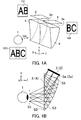
FIGs. 1A and 1B are perspective and side views of an observation optical system according to a first embodiment. -
FIGs. 2A and 2B are top views of the observation optical system illustrated inFIGs. 1A and 1B according to the first embodiment. -
FIG. 3 is a perspective view of a modification of the observation optical system illustrated inFIGs. 1A and 1B according to the first embodiment. -
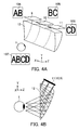
FIGs. 4A and 4B are perspective and side views of an observation optical system according to a second embodiment. -
FIGs. 5A, 5B, and 5C are top views of the observation optical system illustrated inFIGs. 4A and 4B according to the second embodiment. -
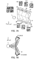
FIGs. 6A and 6B are perspective and side views of an observation optical system according to a third embodiment. -
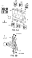
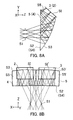
FIGs. 7A and 7B are perspective and side views of an observation optical system according to a fourth embodiment. -
FIGs. 8A and 8B are perspective and side views of a numerical example 1 according to the first embodiment. - Referring now to the accompanying drawings, a description will now be given of a variety of observation optical systems according to embodiments of the present invention. The observation optical system introduces light fluxes from a plurality of display elements each configured to display an original image to an exit pupil via a plurality of optical units and presents a combined image. The observation optical system is suitable for an image display apparatus, such as an HMD.
- Herein, there are defined a Z axis in which a direction parallel to a visual axis OA from an eyeball of an observer to an observation optical system is positive, a Y axis orthogonal to the Z axis, in which an upward vertical direction is positive from the eyeball of the observer, and an X axis in which a left horizontal direction is positive from the eyeball of the observer.
-
FIG. 1A is a perspective view of an observation optical system according to a first embodiment, andFIG. 1B is its side view. InFIGs. 1A and 1B ,reference numeral 1 denotes an eyeball of an observer, arranged at or near a position of an exit pupil S1 of the observation optical system.Reference numeral 2 denotes a (first) display element configured to display an original image, andreference numeral 3 denotes a (second) display element configured to display an original image.Reference numeral 4 denotes a (first) optical unit, andreference numeral 5 denotes a (second) optical unit. Theoptical units -
Reference numeral 101 denotes a (first original) image displayed on adisplay plane 2a of thedisplay element 2,reference numeral 102 denotes a (second original) image displayed on adisplay plane 3a of thedisplay element 3, andreference numeral 103 denotes a combined image observed by the observer via the observation optical system. - As illustrated in
FIG. 1B , the light fluxes from thedisplay elements optical units optical units display planes display elements - A decentering section of each of the
optical units FIG. 1B , the surface S3 is a decentering reflective curved surface. The decentering sections of the plurality ofoptical units optical units - The
display elements - The two
display elements display planes - In other words, as understood from the two
images FIG. 1A , thedisplay element 2 has a normal (non-overlap) display area configured to display an image A and an overlap area configured to display an image B. Thedisplay element 3 has an overlap area configured to display an image B and a normal (non-overlap) display area configured to display an image C. - The two
images display element 2 is provided on a side of thedisplay element 3 and the overlap area of thedisplay element 3 is provided on a side of thedisplay element 2. - The
display elements display planes display elements - In particular, when the display elements are arranged at different slope angles, an electronic circuit substrate (not illustrated) mounted with each display element and configured to drive each display element is arranged parallel to the display element at a similar angle. Therefore, the conventional structure has a problem in that the space around the display element is likely to be large in the Y axis direction. The observation optical system of this embodiment solves this problem, and achieves a compact structure in the Y axis direction. According to this embodiment, the electronic circuit substrate can be commonly used to drive the
display elements - In
FIG. 1A , theoptical units display elements - This embodiment folds an optical path utilizing a plurality of decentering reflective curved surfaces of the
optical units optical units - The exit surfaces of the
optical units - As illustrated in
FIG. 1B , a ray from thedisplay element 2 is twice reflected in theoptical unit 4, a ray from thedisplay element 3 is twice reflected in theoptical unit 5, and these rays are guided to theeyeball 1. The surface S2 has a surface serving a reflection and transmission, and an internal total reflection may be desirable so as to cut a loss of the light quantity. In addition, when all surfaces of theoptical units 4 and 5 (surfaces S2, S3 and S5) on the optical paths are curved surface, all surfaces contribute to converging, diverging, or aberrational corrections, and are expected to provide an effect of the cost reduction by reducing unnecessary surfaces. - When at least one surface in the
optical units -
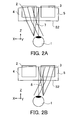
FIG. 2A illustrates rays led to theeyeball 1 from thedisplay element 2, andFIG. 2B illustrates rays led to theeyeball 1 from thedisplay element 3. - As illustrated in
FIGs. 2A and 2B , a ray at a left field angle and aray 7 at a right field angle corresponding to the overlap area are led to theeyeball 1 from thedisplay element 2. Aray 8 at a left field angle corresponding to the overlap area and a ray having a right field angle are led to theeyeball 1 from thedisplay element 3. - Due to the overlap areas configured to duplicately display the same image in the combined image, chipping of the image can be prevented near the boundary of the combined image, and a seamless image can be observed when the eyeball rotates. In addition, a shift of the boundary in the combined image caused by a manufacturing error of a prism and a positional offset between the display element and the prism can be adjusted in the overlap areas.
- Since the overlap areas in the combined image, in which images from the two display elements overlap each other, the brightness becomes twice as high as the other image portions. There may be provided a light-intensity controller configured to control the light intensity at the exit pupil about the overlap area configured to display the same image.
- For example, a light attenuator, such as an ND filter may be arranged above the overlap area in the image of the display element, or an image that has previously reduced brightness may be displayed. In order to reduce the brightness on the display element, the brightness may be half as low as another image over the overlap area, or the brightness may be gradually reduced as a position approaches to the end of the display element. The latter case provides a more natural combined image because the brightness gently changes on the display element.
- In the optical system that utilizes the decentering reflective curved surface as in this embodiment, the aberrations are less influential when the power of the optical system is increased in the direction vertical to the decentering section. Hence, the power can be increased when the display field angle is widened by the overlap area. Since the focal length becomes shorter, the size vertical to the decentering section can be reduced.
- This embodiment forms the
optical units optical units - While the optical element (prism) of this embodiment includes two
optical units FIG. 3 , or three or more as in the second embodiment, which will be described later. -
FIG. 3 is a perspective view when two optical units are formed in anoptical unit 6. Thereby, handling of the optical element becomes simpler, and holding becomes easier. As described above, the exit surface of theoptical unit 6 is the same plane parallel to the XY plane, and enables a smooth and continuous image to be observed while the continuity of the light flux that has passed theoptical unit 6 is maintained. - While this embodiment utilizes the observation optical system that divides the horizontal field angle into two in the X axis direction, this embodiment is applicable to an optical system that divides the vertical field angle into two in the Y direction. Each optical unit may be inclined and the line of intersection between the decentering sections may not be parallel to the Y axis. A plurality of optical unit may be arranged so that the decentering sections can be parallel to each other instead of intersecting each other.
- This embodiment closely arranges the
display elements display elements -
FIG. 4A is a perspective view of an observation optical system according to a second embodiment, andFIG. 4B is its side view. - This embodiment divides a horizontal field angle into three. The display field angle is set to a horizontal field angle of 100° and a vertical field angle of 38°. The overlap area displays the same image in an angular range of 10° between the two neighboring
display elements - In
FIGs. 4A and 4B ,reference numeral 9 denotes a (first) display element configured to display an original image,reference numeral 10 denotes a (second) display element configured to display an original image, andreference numeral 11 denotes a (third) display element configured to display an original image.Reference numeral 12 denotes an optical element.Reference numeral 104 denotes a (first) image displayed on thedisplay element 9,reference numeral 105 denotes a (second) image displayed on thedisplay element 10,reference numeral 106 denotes a (third) image displayed on thedisplay element 11, andreference numeral 107 denotes a combined image observed by the observer via the observation optical system. - The
display elements display elements display elements display elements - The
display elements display elements - In particular, when the display elements are arranged at different slope angles, electronic circuit substrates (not illustrated) each mounted with and configured to drive a corresponding one of display elements are arranged parallel to the display elements at similar slope angles. Therefore, the conventional structure has a problem in that the space around the display elements is likely to enlarge in the Y axis direction. The observation optical system of this embodiment solves this problem, and achieves a compact structure in the Y axis direction. According to this embodiment, the electronic circuit substrate can be commonly used to drive the
display elements - The
display element 9 displays an image in an angular range of 35° between the horizontal field angle of +50° and the horizontal field angle of +15°. Thedisplay element 10 displays an image in an angular range of 50° between the horizontal field angle of +25° and the horizontal field angle of -25°. Thedisplay element 11 displays an image in an angular range of 35° between the horizontal field angle of -15° and the horizontal field angle of -50°. - The material and function of the optical unit of the
optical element 12 are similar to those of the first embodiment. It is similar to the first embodiment that the optical unit reflects the light flux twice, the internal total reflection may be formed, and the curved outer surface having a rotationally asymmetrical shape may be formed. -
FIG. 5A illustrates rays introduced to theeyeball 1 from thedisplay element 9,FIG. 5B illustrates rays introduced to theeyeball 1 from thedisplay element 10, andFIG. 5C illustrates rays introduced to theeyeball 1 from thedisplay element 11. As illustrated inFIG. 5A , a ray having a left field angle and aray 13 having a right field angle corresponding to the overlap area are introduced into theeyeball 1 from thedisplay element 9. As illustrated inFIG. 5B , aray 14 having a left field angle corresponding to the overlap area and aray 15 having a right field angle corresponding to the overlap area are introduced into theeyeball 1 from thedisplay element 10. As illustrated inFIG. 5C , aray 16 having a left field angle corresponding to the overlap area and a ray having a right field angle are introduced into theeyeball 1 from thedisplay element 11. - Due to the overlap areas, this embodiment, similar to the first embodiment, can prevent an image from chipping when the eyeball rotates, and absorb a manufacturing error of the prism and a positional offset between the display element and the prism. It is similar to the first embodiment that the light-intensity controller may be provided for the overlap area, and the miniaturization can be achieved by increasing the power when the overlap area widens the display field angle.
- Even in this embodiment, a plurality of optical units may be integrated, similar to the first embodiment. At this time, the exit surfaces of the three optical units may provide the same plane. In addition, when there are three optical units, the two neighboring optical units may be jointed together.
- While this embodiment utilizes the observation optical system configured to divide the horizontal field angle in the X axis direction into three, this embodiment is applicable to an optical system configured to divide the vertical field angle into three in the Y axis direction.
- This embodiment closely arranges the
display elements -
FIG. 6A is a perspective view of an observation optical system according to a third embodiment, andFIG. 6B is its side view. - This embodiment arranges two optical elements (prisms) 23 and 24 each of which divides a horizontal field angle into three, so as to divide a vertical field angle into two.
- The display field angle is set to a horizontal field angle of 100° and a vertical field angle of 38°. The overlap area displays the same image between the two neighboring elements corresponds to 10°. Although there is no overlap area in the vertical direction, the light fluxes introduced to the same image point in the combined image have an overlap in the exit pupil plane.
- In
FIGs. 6A and 6B ,reference numerals 17 to 19 denote first to third display elements each configured to display an original image.Reference numerals 20 to 22 denote fourth to sixth display elements each configured to display an original image.Reference numerals Reference numerals 108 to 110 denote first to third images displayed on thedisplay elements 17 to 19.Reference numerals 111 to 113 denote fourth to sixth images displayed on thedisplay elements 20 to 22.Reference numeral 114 denotes a combined image observed by the observer via the observation optical system. Incident surfaces of the plurality of optical units of the firstoptical element 23 are arranged opposite to those of the plurality of optical units of the secondoptical element 24 with respect to the visual axis. - The
display elements 17 to 22 are structurally similar to thedisplay elements display elements - The
display elements 17 to 19 have rectangular shapes, and are arranged adjacent to one another so that they form the same plane. Thereby, the observation optical system becomes smaller (thinner) in the Y axis direction than the conventional structure in which thedisplay elements 17 to 19 are arranged at different slope angles. - The
display elements 20 to 22 have rectangular shapes, and are arranged adjacent to one another so that they form the same plane. Thereby, the observation optical system becomes smaller (thinner) in the Y axis direction than the conventional structure in which thedisplay elements 20 to 22 are arranged at different slope angles. In the meanwhile, the display planes of the upper and lower display elements are not parallel to each other. - In particular, when the display elements are arranged at different slope angles, electronic circuit substrates (not illustrated) each mounted with and configured to drive a corresponding one of display elements are arranged parallel to the display elements at similar slope angles. Therefore, the conventional structure has a problem in that the space around the display elements is likely to be large in the Y axis direction. The observation optical system of this embodiment solves this problem, and achieves a compact structure in the Y axis direction. According to this embodiment, the electronic circuit substrate is commonly used to drive the
display elements 17 to 19, and the electronic circuit substrate is commonly used to drive thedisplay elements 20 to 22, and the miniaturization of the observation optical system in the Y axis direction is promoted in this case. - The
display element 17 displays an image in an angular range of 35° between the horizontal field angle of +50° and the horizontal field angle of +15°. Thedisplay element 18 displays an image in an angular range of 50° between the horizontal field angle of +25° and the horizontal field angle of -25°. Thedisplay element 19 displays an image in an angular range of 35° between the horizontal field angle of -15° and the horizontal field angle -50°. The vertical field angle displayed by thedisplay elements - The
display element 20 displays an image in an angular range of 35° between the horizontal field angle of +50° and the horizontal field angle of +15°. Thedisplay element 21 displays an image in an angular range of 50° between the horizontal field angle of +25° and the horizontal field angle of -25°. Thedisplay element 22 displays an image in an angular range of 35° between the horizontal field angle of -15° and the horizontal field angle of -50°. The vertical field angle displayed by thedisplay elements - This embodiment folds an optical path utilizing a plurality of decentering reflective curved surfaces of the optical units of the
optical elements optical elements optical element 23 has a shape different from that of theoptical element 24. Each of theoptical elements - This embodiment divides the original image into two in the vertical direction, and makes thinner the observation optical system in the Z axis direction. The decentering section of the optical unit at the center of the
optical element 23 is the same as that of the optical unit at the center of theoptical element 24. - As illustrated in
FIG. 6B , a ray from each of thedisplay elements optical element 23, and led to theeyeball 1. A ray from each of thedisplay elements optical element 24, and led to theeyeball 1 through theoptical element 23. - It is similar to the first embodiment that each of the exit surface of the
optical element 23 to the eyeball and the exit surface of theoptical element 24 to theoptical element 23 may provide the internal total reflection. It is also similar to the first embodiment that all surfaces of theoptical elements optical elements - This embodiment also provides the overlap area configured to display the same image, to the image on each display element that is divided in the horizontal direction. Therefore, the overlap area can prevent an image from chipping when the eyeball rotates in the horizontal direction, and absorb a manufacturing error of a prism and a positional offset between the display element and the prism.
- This embodiment provides no overlap area in the divisions in the vertical direction, but instead the light fluxes introduced to the same image point in the combined image have an overlap in the exit pupil. Even in this configuration, similar to case where the overlap area is provided, the light fluxes of any angles of view are introduced to the exit pupil, and thus chipping of the image can be eliminated when the eyeball rotates in the vertical direction.
- It is similar to the first embodiment that the light-intensity controller for each of the overlap area and the overlap section may be provided, and the miniaturization can be achieved by increasing the power when the overlap area widens the display field angle.
- This embodiment may integrate three optical units into one optical element that serves as the
optical elements - Thus, an image at a wider field angle can be displayed by increasing the number of divisions in the combined image, and the size of each usable display element can be reduced. Thus, an image display apparatus providing an intended display field angle can be realized without relying upon the size of the usable display element.
- This embodiment divides the horizontal field angle into three in the X axis direction, and the vertical field angle into two in the Y axis direction, providing the observation optical system configured to provide totally six divisions. The six divisions may be provided by exchanging the X axis and the Y axis. Each optical unit may be inclined and the line of intersection between the decentering sections may not be parallel to the Y axis. Moreover, similar to the division in the horizontal direction, the overlap area may be provided for the divisions in the vertical direction.
- This embodiment closely arranges display elements by positioning three optical units, and two optical elements each configured to divide the horizontal field angle into three so that they can divide the vertical field angle into two. This configuration can make compact the space around the display elements, and enables one electronic circuit substrate to drive a plurality of display elements.
-
FIG. 7A is a perspective view of an observation optical system according to a fourth embodiment, andFIG. 7B is its side view. - The optical element (prism) 31 of this embodiment arranges three optical units, divides a horizontal field angle into three, and a vertical field angle into two by arranging another pair of three optical units upside down.
- The display field angle is set to a horizontal field angle of 100° and a vertical field angle of 38°. The overlap area displays the same image in an angular range of 10° between the two neighboring elements in the horizontal direction. The overlap area displays the same image in an angular range of 20° between the two neighboring elements in the perpendicular direction.
- In
FIGs. 7A and 7B ,reference numerals 25 to 27 denote first to third display elements each configured to display an original image.Reference numerals 28 to 30 denote fourth to sixth display elements each configured to display an original image.Reference numeral 31 denotes an optical element including six optical units.Reference numerals 115 to 117 denote first to third images displayed on thedisplay elements 25 to 27.Reference numerals 118 to 120 are fourth to sixth images displayed on thedisplay elements 28 to 30. Reference numeral 121 denotes a combined image observed by the observer via the observation optical system. - The
display elements 25 to 30 are structurally similar to thedisplay elements display elements display elements - The
display elements 25 to 27 have rectangular shapes, and are arranged adjacent to one another so that they form the same plane. Thereby, the observation optical system becomes smaller (thinner) in the Y axis direction than the conventional structure in which thedisplay elements 25 to 27 are arranged at different slope angles. - The
display elements 28 to 30 have rectangular shapes, and are arranged adjacent to one another so that they form the same plane. Thereby, the observation optical system becomes smaller (thinner) in the Y axis direction than the conventional structure in which thedisplay elements 28 to 30 are arranged at different slope angles. In the meanwhile, the upper and lower display planes of the display elements are not parallel to one another. - In particular, when the display elements are arranged at different slope angles, electronic circuit substrates (not illustrated) each mounted with and configured to drive a corresponding one of display elements are arranged parallel to the display elements at similar slope angles. Therefore, the conventional structure has a problem in that the space around the display elements is likely to enlarge in the Y axis direction. The observation optical system of this embodiment solves this problem, and achieves a compact structure in the Y axis direction. According to this embodiment, the electronic circuit substrate can be commonly used to drive the
display elements 25 to 27, the electronic circuit substrate can be commonly used to drive thedisplay elements 28 to 30, and the miniaturization of the observation optical system in the Y axis direction is promoted in this case. - The
display element 25 displays an image in an angular range of 35° between the horizontal field angle of +50° and the horizontal field angle of +15°. Thedisplay element 26 displays an image in an angular range of 50° between the horizontal field angle of +25° and the horizontal field angle of -25°. Thedisplay element 27 displays an image in an angular range of 35° between the horizontal field angle of -15° and the horizontal field angle -50°. The vertical field angle displayed by thedisplay elements - The
display element 28 displays an image in an angular range of 35° between the horizontal field angle of +50° and the horizontal field angle of +15°. Thedisplay element 29 displays an image in an angular range of 50° between the horizontal field angle of +25° and the horizontal field angle of -25°. The display element 30 displays an image in an angular range of 35° between the horizontal field angle of -15° and the horizontal field angle of -50°. The vertical field angle displayed by thedisplay elements - This embodiment folds an optical path utilizing a plurality of decentering reflective curved surfaces of the optical units, and reduces the size of the observation optical system in the Z axis direction. The
optical element 31 is made of a material similar to that of the first embodiment. The upper and lower optical units are symmetrically arranged. - This embodiment divides the original image into two in the vertical direction, and makes thinner the observation optical system in the Z axis direction. The decentering section of the optical unit at the upper center of the
optical element 31 is the same as that of the optical unit at the lower center of theoptical element 31. It is similar to the first embodiment that the optical unit reflects the light flux twice, the internal total reflection may be formed, and the curved outer surface having a rotationally asymmetrical shape may be formed. - This embodiment provides an overlap area configured to display the same image to each image of each of the display elements that are horizontally and vertically divided. Therefore, similar to the third embodiment, this embodiment can prevent an image from chipping when the eyeball rotates, and absorb a manufacturing error of the prism and a positional offset between the display element and the prism.
- It is similar to the first embodiment that the light-intensity controller may be provided for the overlap area, and the miniaturization can be achieved by increasing the power when the overlap area widens the display field angle.
- In the optical system that utilizes the decentering reflective curved surface as in this embodiment, the aberrations is less influential when the power of the optical system is increased in the direction vertical to the decentering section. Hence, the power can be increased when the display field angle is widened by the overlap area. Since the focal length becomes shorter, the size vertical to the decentering section can be reduced.
- When six optical units are integrated into one
optical element 31 as in this embodiment, handling of the optical element becomes simpler and its holding becomes easier. As described above, the exit surfaces of the six optical units may provide the same plane. The same plane enables a smooth and continuous image to be observed because the continuity of the light flux that has passed the optical units is maintained. - It is similar to the above embodiments that when the optical elements are formed by dividing the six optical units separately, two neighboring optical units in the horizontal direction and two neighboring optical units in the vertical direction may be joined together.
- By increasing the number of divisions of the combined image, an image at a wider field angle can be displayed and the usable display element may be made smaller. Therefore, the image display apparatus having an intended display field angle can be realized without relying upon the size of the usable display element.
- This embodiment divides the horizontal field angle into three in the X axis direction, and the vertical field angle into two in the Y axis direction, providing the observation optical system configured to provide totally six divisions. However, the six divisions may be provided by exchanging the X axis and the Y axis.
- This embodiment closely arranges the display elements by arranging three optical units and the same three optical units upside down so as to divide the vertical field angle into two. This configuration can make compact the space around the display elements, and enables one electronic circuit substrate to drive a plurality of display elements.
-
FIG. 8A is a side view of an observation optical system according to a numerical example 1 of the first embodiment.FIG. 8B is its top view. In the numerical example 1, the display element is set to an image plane, and a reverse ray tracing from the pupil position of the eyeball is illustrated. As illustrated, reference numeral S1 denotes an exit pupil, reference numeral SI denotes a display plane of thedisplay element 2, SI' denotes a display plane of thedisplay element 3. The surfaces S2 and S4 form the same plane, and the exit surfaces of the optical element form the same plane, as illustrated inFIG. 3 . - A ray from the display plane SI of the
display element 2 enters theoptical unit 4 through the surface S5, is reflected on the surfaces S4 and S3, exits from theoptical unit 4 through the surface S2, and is guided to the exit pupil S1. A ray from the display plane SI' of thedisplay element 3 enters theoptical unit 5 through the surface S5', is reflected on the surfaces S4 and S3', exits from theoptical unit 5 through the surface S2, and is guided to the exit pupil S1. - The reflection on the surface S4 may be the internal total reflection so as to cut a loss of the light quantity, and the surfaces S2, S3, S3', S4, S5, and S5' are rotationally asymmetrical surfaces each having a plane-symmetry shape having one symmetrical surface. The plane-symmetry shape makes handing and manufacturing easier than those in the asymmetrical case.
- Table 1 illustrates optical data of this numerical example.
Table 1 SURF X Y Z A B R TYP Nd νd 1 0 0 0 0 0 2 0 0 20.00 -0.01 0 -20671.1217 FFS1 1.5709 33.8 3 0 -19.25 2228 -37.03 6.52 -89.0504 FFS2 -1.5709 33.8 4 0 0 20.00 -0.01 0 -20671.1217 FFS1 1.5709 33.8 5 0 29.26 25.63 60.10 6.44 -90.1487 FFS3 1 1 0 35.00 27.00 49.00 0 FS1 c1 -1.36E+02 c5 -7.06E-05 c6 1.52E-05 c10 -6.59E-07 c11 -1.03E-05 c12 -5.72E-08 c13 -5.99E-08 c14 -239E-08 c20 -6.39E-11 c21 -5.92E-10 c22 -1.07E-09 c23 3.23E-11 c24 -4.26E-12 c25 -3.29E-12 c26 -1.05E-12 FFS2 c1 -9.30E-03 c5 -2.97E-04 c6 -1.98E-05 c10 4.33E-07 c11 -3.19E-06 c12 4.09E-08 c13 -4.61E-09 c14 5.44E-10 c20 -6.62E-12 c21 -6.19E-11 c22 1.33E-10 c23 1.61E-11 c24 -1.49E-13 c25 2.12E-13 c26 -7.79E-14 FFS3 c1 1.75E+00 c5 -1.18E-03 c6 1.26E-03 c10 -1.00E-05 c11 1.69E-05 c12 -7.28E-07 c13 -4.03E-07 c14 -4.65E-08 c20 4.28E-09 c21 3.14E-09 c22 220E-09 c23 -3.81E-09 c24 -6.74E-10 c25 -2.44E-10 c26 -1.44E-10 - This embodiment has an elliptical exit pupil with a minor axis of 9.6 mm in the vertical direction and a major axis of 12 mm in the horizontal direction. The
display element 2 has an image display size of about 0.81 inches (11.4mmx17.2mm), and displays an image of a horizontal field angle of 50° (overlap area in an angular range of 24°) and a vertical field angle of 38° at infinity in the positive direction of the Z axis. Since this embodiment displays and divides the horizontal field angle utilizing the two display elements, the horizontal angle of thedisplay element 2 corresponds to 37° from +25° to -12°. The vertical field angle of 38° remains since it is not divided. - The data of the
optical unit 5 of this embodiment corresponds to the data in Table 1 in which codes of B values for the surfaces S3 and S5 are turned into negative. - In Table 1, "SURF" denotes a surface number, and X, Y, and Z denote X, Y, and Z coordinate values at each surface vertex. "A" denotes a rotation around the X axis expressed with a degree as the unit where the counterclockwise direction is set to the positive direction. "B" denotes a rotation around the Y axis expressed with a degree as the unit where the counterclockwise direction is set to the positive direction. "R" denotes a radius of curvature. "TYP" denotes a type of a surface shape. "FFS" denotes a rotationally asymmetrical surface expressed by the following expression. A number subsequent to "FFS" denotes an aspheric coefficient expressed in the column of a corresponding number under the table. A value of the coefficient is 0 when there is no aspheric coefficient. Nd and vd denote a refractive index and Abbe number for the d-line of a material subsequent to the target surface. When the medium is air, only the refractive index Nd is expressed as 1.000 and the Abbe number vd is not displayed: FFS:


- While the present invention has been described with reference to exemplary embodiments, it is to be understood that the invention is not limited to the disclosed exemplary embodiments. The scope of the following claims is to be accorded the broadest interpretation so as to encompass all such modifications and equivalent structures and functions.
Claims (12)
- An image display apparatus comprising:a plurality of display elements (2, 3) each configured to display an original image (101, 102); andan observation optical system configured to introduce light fluxes from the plurality of display elements to an exit pupil (S1) via a plurality of optical units (4, 5), and to present a combined image (103),characterized in thatthe plurality of display elements include two neighboring display elements, and display planes of the two display elements partially display the same image; andwhen a decentering section of each optical unit is defined as a section formed by a principal ray of the light flux introduced to the same image point in the combined image when the principal ray is reflected, the plurality of optical units are arranged so thatdecentering sections of the plurality of optical units are parallel, ora line of intersections between the decentering sections of the plurality of optical units does not accord with a line that is made by connecting a center of the exit pupil and an arbitrary point in the combined image.
- The image display apparatus according to claim 1, wherein the plurality of optical units are arranged so that decentering sections of the plurality of optical units are parallel.
- The image display apparatus according to claim 1, wherein the plurality of optical units are arranged so that a line of intersections between the decentering sections of the plurality of optical units does not accord with a line that is made by connecting a center of the exit pupil and an arbitrary point in the combined image.
- The image display apparatus according to any one of claims 1 to 3, further comprising an electronic circuit substrate mounted with and configured to drive the two display elements.
- The image display apparatus according to any one of claims 1 to 3, characterized in that exit surfaces of the plurality of optical units form the same optical plane.
- The image display apparatus according to any one of claims 1 to 3, characterized in that two optical units corresponding to the two display elements are formed as two separate members and jointed together.
- The image display apparatus according to any one of claims 1 or 3, characterized in that two optical units corresponding to the two display elements are formed as part of one optical element.
- The image display apparatus according to any one of claims 1 or 3, characterized in that the observation optical system includes a first optical element and a second optical element,
wherein incident surfaces of a plurality of optical units of the first optical element are located on opposite side of those of the second optical element, and
wherein each of the plurality of optical units of the first optical element and the plurality of optical units of the second optical element include optical units that has a common decentering section. - The image display apparatus according to claim 8, characterized in that a display plane of a display element that corresponds to the first optical element and a display plane of a display element that corresponds to the second optical element partially display the same image.
- The image display apparatus according to any one of claims 1 to 9, further comprising a light-intensity controller configured to control a light intensity on the exit pupil corresponding to a portion that displays the same image in the plurality of display elements.
- The image display apparatus according to claim 8, characterized in that light fluxes from the first optical element and the second optical element to the same image point in the combined image have an overlap on the exit pupil.
- The image display apparatus according to claim 11, further comprising a light-intensity controller configured to control a light intensity of the overlap on the exit pupil.
Applications Claiming Priority (1)
| Application Number | Priority Date | Filing Date | Title |
|---|---|---|---|
| JP2011186821A JP5875295B2 (en) | 2011-08-30 | 2011-08-30 | Image display device |
Publications (2)
| Publication Number | Publication Date |
|---|---|
| EP2565700A2 true EP2565700A2 (en) | 2013-03-06 |
| EP2565700A3 EP2565700A3 (en) | 2013-06-05 |
Family
ID=47115115
Family Applications (1)
| Application Number | Title | Priority Date | Filing Date |
|---|---|---|---|
| EP12006136.1A Withdrawn EP2565700A3 (en) | 2011-08-30 | 2012-08-29 | Image display apparatus |
Country Status (3)
| Country | Link |
|---|---|
| US (1) | US9030747B2 (en) |
| EP (1) | EP2565700A3 (en) |
| JP (1) | JP5875295B2 (en) |
Cited By (6)
| Publication number | Priority date | Publication date | Assignee | Title |
|---|---|---|---|---|
| WO2016036738A1 (en) * | 2014-09-02 | 2016-03-10 | Ostendo Technologies, Inc. | Split exit pupil heads-up display systems and methods |
| CN107407817A (en) * | 2015-01-21 | 2017-11-28 | 特塞兰德有限责任公司 | Display device with total internal reflection |
| GB2557942A (en) * | 2016-12-19 | 2018-07-04 | Sharp Kk | Apparatus to achieve compact head mounted display with reflectors and eyepiece element |
| EP3407112A1 (en) * | 2017-05-26 | 2018-11-28 | Qioptiq Limited | Distributed aperture head-up display (hud) |
| US10539791B2 (en) | 2014-09-02 | 2020-01-21 | Ostendo Technologies, Inc. | Split exit pupil multiple virtual image heads-up display systems and methods |
| US10845591B2 (en) | 2016-04-12 | 2020-11-24 | Ostendo Technologies, Inc. | Split exit pupil heads-up display systems and methods |
Families Citing this family (14)
| Publication number | Priority date | Publication date | Assignee | Title |
|---|---|---|---|---|
| US10156722B2 (en) * | 2010-12-24 | 2018-12-18 | Magic Leap, Inc. | Methods and systems for displaying stereoscopy with a freeform optical system with addressable focus for virtual and augmented reality |
| US9915826B2 (en) | 2013-11-27 | 2018-03-13 | Magic Leap, Inc. | Virtual and augmented reality systems and methods having improved diffractive grating structures |
| US9857591B2 (en) | 2014-05-30 | 2018-01-02 | Magic Leap, Inc. | Methods and system for creating focal planes in virtual and augmented reality |
| EP4071537A1 (en) | 2014-01-31 | 2022-10-12 | Magic Leap, Inc. | Multi-focal display system |
| EP3100098B8 (en) | 2014-01-31 | 2022-10-05 | Magic Leap, Inc. | Multi-focal display system and method |
| EP4235252A1 (en) | 2014-05-30 | 2023-08-30 | Magic Leap, Inc. | Methods and system for creating focal planes in virtual augmented reality |
| AU2015266670B2 (en) | 2014-05-30 | 2019-05-09 | Magic Leap, Inc. | Methods and systems for displaying stereoscopy with a freeform optical system with addressable focus for virtual and augmented reality |
| CN111781726B (en) | 2015-01-26 | 2022-05-10 | 奇跃公司 | Virtual and augmented reality systems and methods with improved diffraction grating structures |
| EP3440486A4 (en) | 2016-04-07 | 2019-04-24 | Magic Leap, Inc. | Systems and methods for augmented reality |
| CN107544145B (en) * | 2016-06-28 | 2021-06-01 | 松下知识产权经营株式会社 | Head-mounted display device |
| JP2019074678A (en) * | 2017-10-18 | 2019-05-16 | セイコーエプソン株式会社 | Eyepiece optical system and image display device |
| US10969586B2 (en) * | 2018-07-10 | 2021-04-06 | Darwin Hu | Ultra light-weight see-through display glasses |
| JP2020076934A (en) * | 2018-11-09 | 2020-05-21 | ソニー株式会社 | Virtual image display unit and virtual image display method |
| US20220003989A1 (en) * | 2018-11-09 | 2022-01-06 | Sony Corporation | Virtual image display apparatus and virtual image display method |
Citations (2)
| Publication number | Priority date | Publication date | Assignee | Title |
|---|---|---|---|---|
| JP2009115906A (en) | 2007-11-02 | 2009-05-28 | Canon Inc | Image display apparatus |
| JP2010266787A (en) | 2009-05-18 | 2010-11-25 | Canon Inc | Image display apparatus |
Family Cites Families (9)
| Publication number | Priority date | Publication date | Assignee | Title |
|---|---|---|---|---|
| JP2911750B2 (en) * | 1994-06-13 | 1999-06-23 | キヤノン株式会社 | Observation optical system |
| DE69534221T2 (en) | 1994-06-13 | 2006-01-26 | Canon K.K. | display device |
| JP3309615B2 (en) * | 1994-12-21 | 2002-07-29 | キヤノン株式会社 | Image observation apparatus and binocular image observation apparatus using the same |
| JPH08327946A (en) * | 1995-05-31 | 1996-12-13 | Olympus Optical Co Ltd | Visual display device |
| JPH09166759A (en) * | 1995-12-18 | 1997-06-24 | Olympus Optical Co Ltd | Picture display device |
| JP5031452B2 (en) * | 2007-06-20 | 2012-09-19 | キヤノン株式会社 | Image observation apparatus and image observation system |
| JP5268342B2 (en) * | 2007-12-14 | 2013-08-21 | キヤノン株式会社 | Image display device |
| JP5556019B2 (en) * | 2009-01-27 | 2014-07-23 | 日本精機株式会社 | Head-up display device |
| JP5111434B2 (en) * | 2009-05-18 | 2013-01-09 | キヤノン株式会社 | Observation optical system and image display device |
-
2011
- 2011-08-30 JP JP2011186821A patent/JP5875295B2/en not_active Expired - Fee Related
-
2012
- 2012-08-27 US US13/595,051 patent/US9030747B2/en not_active Expired - Fee Related
- 2012-08-29 EP EP12006136.1A patent/EP2565700A3/en not_active Withdrawn
Patent Citations (2)
| Publication number | Priority date | Publication date | Assignee | Title |
|---|---|---|---|---|
| JP2009115906A (en) | 2007-11-02 | 2009-05-28 | Canon Inc | Image display apparatus |
| JP2010266787A (en) | 2009-05-18 | 2010-11-25 | Canon Inc | Image display apparatus |
Cited By (12)
| Publication number | Priority date | Publication date | Assignee | Title |
|---|---|---|---|---|
| WO2016036738A1 (en) * | 2014-09-02 | 2016-03-10 | Ostendo Technologies, Inc. | Split exit pupil heads-up display systems and methods |
| US9494794B2 (en) | 2014-09-02 | 2016-11-15 | Ostendo Technologies, Inc. | Split exit pupil heads-up display systems and methods |
| CN106796349A (en) * | 2014-09-02 | 2017-05-31 | 奥斯坦多科技公司 | Segmentation emergent pupil head-up display system and method |
| CN106796349B (en) * | 2014-09-02 | 2019-11-19 | 奥斯坦多科技公司 | Divide emergent pupil head-up display system and method |
| US10539791B2 (en) | 2014-09-02 | 2020-01-21 | Ostendo Technologies, Inc. | Split exit pupil multiple virtual image heads-up display systems and methods |
| CN107407817A (en) * | 2015-01-21 | 2017-11-28 | 特塞兰德有限责任公司 | Display device with total internal reflection |
| EP3248053A4 (en) * | 2015-01-21 | 2018-10-24 | Tesseland LLC | Display device with total internal reflection |
| US10436951B2 (en) | 2015-01-21 | 2019-10-08 | Tesseland, Llc | Display device with total internal reflection |
| US10845591B2 (en) | 2016-04-12 | 2020-11-24 | Ostendo Technologies, Inc. | Split exit pupil heads-up display systems and methods |
| GB2557942A (en) * | 2016-12-19 | 2018-07-04 | Sharp Kk | Apparatus to achieve compact head mounted display with reflectors and eyepiece element |
| EP3407112A1 (en) * | 2017-05-26 | 2018-11-28 | Qioptiq Limited | Distributed aperture head-up display (hud) |
| US10409077B2 (en) | 2017-05-26 | 2019-09-10 | Qioptiq Limited | Distributed aperture head up display (HUD) |
Also Published As
| Publication number | Publication date |
|---|---|
| US9030747B2 (en) | 2015-05-12 |
| JP5875295B2 (en) | 2016-03-02 |
| US20130050832A1 (en) | 2013-02-28 |
| JP2013050487A (en) | 2013-03-14 |
| EP2565700A3 (en) | 2013-06-05 |
Similar Documents
| Publication | Publication Date | Title |
|---|---|---|
| EP2565700A2 (en) | Image display apparatus | |
| EP2253989A2 (en) | Image display apparatus | |
| US10809533B2 (en) | Wide angle and high resolution tiled head-mounted display device | |
| US8317330B2 (en) | Image display apparatus | |
| JP6065630B2 (en) | Virtual image display device | |
| KR101556839B1 (en) | Eyepiece for near-to-eye display with multi-reflectors | |
| US7081999B2 (en) | Image display apparatus and head mounted display using it | |
| JP5031272B2 (en) | Display optical system and image display apparatus having the same | |
| JP6221732B2 (en) | Virtual image display device | |
| EP1102105A1 (en) | Image display apparatus | |
| CN106796348A (en) | Guiding device and virtual image display apparatus | |
| US8437087B2 (en) | Observation optical system and image display apparatus | |
| JP2010266787A5 (en) | ||
| CN101846803A (en) | Head-mounted type image display device | |
| US11422371B2 (en) | Augmented reality (AR) display | |
| JP2010266792A5 (en) | ||
| JP2004184773A (en) | Image display device and image display system | |
| JP4591006B2 (en) | Observation optical system and image display device having holographic reflection surface | |
| JP4847055B2 (en) | Image display device and imaging device | |
| EP2565701A2 (en) | Observation optical system and image display apparatus | |
| JP3957961B2 (en) | Image display device and head mounted display using the same | |
| JP2019132956A (en) | Display device | |
| CN216387601U (en) | Viewing system and display device | |
| JP6505059B2 (en) | Image display device and display element | |
| KR20110101931A (en) | Hud system using multi-lens |
Legal Events
| Date | Code | Title | Description |
|---|---|---|---|
| PUAI | Public reference made under article 153(3) epc to a published international application that has entered the european phase |
Free format text: ORIGINAL CODE: 0009012 |
|
| AK | Designated contracting states |
Kind code of ref document: A2 Designated state(s): AL AT BE BG CH CY CZ DE DK EE ES FI FR GB GR HR HU IE IS IT LI LT LU LV MC MK MT NL NO PL PT RO RS SE SI SK SM TR |
|
| AX | Request for extension of the european patent |
Extension state: BA ME |
|
| RIN1 | Information on inventor provided before grant (corrected) |
Inventor name: TOHARA, MASAKAZU Inventor name: INOGUCHI, KAZUTAKA |
|
| PUAL | Search report despatched |
Free format text: ORIGINAL CODE: 0009013 |
|
| AK | Designated contracting states |
Kind code of ref document: A3 Designated state(s): AL AT BE BG CH CY CZ DE DK EE ES FI FR GB GR HR HU IE IS IT LI LT LU LV MC MK MT NL NO PL PT RO RS SE SI SK SM TR |
|
| AX | Request for extension of the european patent |
Extension state: BA ME |
|
| RIC1 | Information provided on ipc code assigned before grant |
Ipc: G02B 27/01 20060101AFI20130430BHEP Ipc: G02B 27/10 20060101ALI20130430BHEP |
|
| 17P | Request for examination filed |
Effective date: 20131205 |
|
| RBV | Designated contracting states (corrected) |
Designated state(s): AL AT BE BG CH CY CZ DE DK EE ES FI FR GB GR HR HU IE IS IT LI LT LU LV MC MK MT NL NO PL PT RO RS SE SI SK SM TR |
|
| STAA | Information on the status of an ep patent application or granted ep patent |
Free format text: STATUS: THE APPLICATION HAS BEEN WITHDRAWN |
|
| 18W | Application withdrawn |
Effective date: 20150805 |