EP2565642B1 - L-mode guided wave sensor - Google Patents
L-mode guided wave sensor Download PDFInfo
- Publication number
- EP2565642B1 EP2565642B1 EP10850747.6A EP10850747A EP2565642B1 EP 2565642 B1 EP2565642 B1 EP 2565642B1 EP 10850747 A EP10850747 A EP 10850747A EP 2565642 B1 EP2565642 B1 EP 2565642B1
- Authority
- EP
- European Patent Office
- Prior art keywords
- inspection target
- guided wave
- coil
- vibrator
- mode guided
- Prior art date
- Legal status (The legal status is an assumption and is not a legal conclusion. Google has not performed a legal analysis and makes no representation as to the accuracy of the status listed.)
- Not-in-force
Links
Images



Classifications
-
- G—PHYSICS
- G01—MEASURING; TESTING
- G01N—INVESTIGATING OR ANALYSING MATERIALS BY DETERMINING THEIR CHEMICAL OR PHYSICAL PROPERTIES
- G01N29/00—Investigating or analysing materials by the use of ultrasonic, sonic or infrasonic waves; Visualisation of the interior of objects by transmitting ultrasonic or sonic waves through the object
- G01N29/22—Details, e.g. general constructional or apparatus details
- G01N29/24—Probes
- G01N29/2412—Probes using the magnetostrictive properties of the material to be examined, e.g. electromagnetic acoustic transducers [EMAT]
-
- G—PHYSICS
- G01—MEASURING; TESTING
- G01N—INVESTIGATING OR ANALYSING MATERIALS BY DETERMINING THEIR CHEMICAL OR PHYSICAL PROPERTIES
- G01N29/00—Investigating or analysing materials by the use of ultrasonic, sonic or infrasonic waves; Visualisation of the interior of objects by transmitting ultrasonic or sonic waves through the object
- G01N29/04—Analysing solids
- G01N29/043—Analysing solids in the interior, e.g. by shear waves
-
- H—ELECTRICITY
- H10—SEMICONDUCTOR DEVICES; ELECTRIC SOLID-STATE DEVICES NOT OTHERWISE PROVIDED FOR
- H10N—ELECTRIC SOLID-STATE DEVICES NOT OTHERWISE PROVIDED FOR
- H10N35/00—Magnetostrictive devices
-
- G—PHYSICS
- G01—MEASURING; TESTING
- G01H—MEASUREMENT OF MECHANICAL VIBRATIONS OR ULTRASONIC, SONIC OR INFRASONIC WAVES
- G01H11/00—Measuring mechanical vibrations or ultrasonic, sonic or infrasonic waves by detecting changes in electric or magnetic properties
- G01H11/02—Measuring mechanical vibrations or ultrasonic, sonic or infrasonic waves by detecting changes in electric or magnetic properties by magnetic means, e.g. reluctance
- G01H11/04—Measuring mechanical vibrations or ultrasonic, sonic or infrasonic waves by detecting changes in electric or magnetic properties by magnetic means, e.g. reluctance using magnetostrictive devices
-
- G—PHYSICS
- G01—MEASURING; TESTING
- G01N—INVESTIGATING OR ANALYSING MATERIALS BY DETERMINING THEIR CHEMICAL OR PHYSICAL PROPERTIES
- G01N2291/00—Indexing codes associated with group G01N29/00
- G01N2291/02—Indexing codes associated with the analysed material
- G01N2291/028—Material parameters
- G01N2291/0289—Internal structure, e.g. defects, grain size, texture
-
- G—PHYSICS
- G01—MEASURING; TESTING
- G01N—INVESTIGATING OR ANALYSING MATERIALS BY DETERMINING THEIR CHEMICAL OR PHYSICAL PROPERTIES
- G01N2291/00—Indexing codes associated with group G01N29/00
- G01N2291/04—Wave modes and trajectories
- G01N2291/042—Wave modes
- G01N2291/0425—Parallel to the surface, e.g. creep waves
-
- G—PHYSICS
- G01—MEASURING; TESTING
- G01N—INVESTIGATING OR ANALYSING MATERIALS BY DETERMINING THEIR CHEMICAL OR PHYSICAL PROPERTIES
- G01N2291/00—Indexing codes associated with group G01N29/00
- G01N2291/26—Scanned objects
- G01N2291/263—Surfaces
- G01N2291/2634—Surfaces cylindrical from outside
Definitions
- the present invention relates to an L-mode guided wave sensor which uses a longitudinal mode (L-mode) guided wave to inspect an inspection target.
- the L-mode guided wave propagates through the inspection target while vibrating in its propagation direction.
- the frequency of the guided wave is, for example, 1 kHz to several hundred kHz (e.g. 32 kHz, 64 kHz, or 128 kHz).
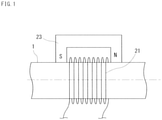
- An L-mode guided wave is generated, for example, by a configuration in FIG. 1 .
- a coil 21 is wound around an inspection target 1 (pipe in the diagram), and a magnet 23 is attached to the inspection target 1. If an alternating current is passed through the coil 21 in this state, an alternating-current magnetic field is generated.
- the inspection target 1 which is a ferromagnetic body is vibrated by a magnetostrictive effect, and a guided wave which is a kind of a sound wave is thereby generated.
- the generated guided wave propagates through the inspection target 1 along its longitudinal direction.
- a reflected wave of the guided wave is detected to inspect the soundness of the inspection target 1.
- the guided wave is reflected as a reflected wave by a discontinuous part in the inspection target 1 and by a change in the cross-sectional area of the inspection target 1.
- the soundness of the inspection target 1 is inspected.
- the inspection target 1 is inspected for defects such as a scarred or corroded part.
- the guided wave As compared with a sound wave used in general sound wave inspections, the guided wave attenuates less and enables the soundness of the inspection target 1 to be inspected over a wide range of the inspection target 1.
- the sound wave used in general sound wave inspections has, for example, a high frequency of 5 MHz and a small wavelength of 0.6 mm, and accordingly easily attenuates.
- the above-mentioned guided wave has, for example, a low frequency of several kHz to several ten kHz and a great wavelength of 100 mm, and accordingly does not easily attenuate.
- US 2004/095137 A1 and US 2007/090904 A1 relate to a method and an apparatus for evaluation of a pipe or a tube using a torsional wave.
- US 2004/095137 also discloses the generation of guide waves in a plate-like structure, by means of a sensor comprising a coil wound around an U-shaped ferromagnetic core placed on the inspected structure and an U-shaped magnet positioned over said coil/core arrangement.
- JP S57 165761 A relates to a transducer for an electro-magnetic ultrasonic wave.
- DE 100 16 468 A1 relates to a run time measurement of acoustic pulse in a magnetoelastic screw.
- US 5 612 495 A relates to a non-destructive evaluation device.
- JP 4 131179 B2 relates to a super-magnetostriction type wideband ultrasonic wave generator.
- the inspection that uses an L-mode guided wave has the following problems (A) and (B).
- the present invention provides an L-mode guided wave sensor as defined in claim 1.
- a method of using the L-mode guide wave sensor is defined in claim 4.
- a magnet is attached to the vibrator, and the magnet has a south pole on one side in the axial direction of the coil and has a north pole on the other side in the axial direction of the coil.
- the vibrator attached to the inspection target is made of a ferromagnetic material, and the coil is wound around the vibrator, so that the dimensions of the coil does not need to be adjusted to the dimensions of the inspection target.
- the L-mode guided wave sensor can be reduced in size.
- an alternating-current magnetic field generated by the coil is applied to the vibrator which is a ferromagnetic body different from the inspection target, and the vibrator is thereby vibrated.
- a guided wave is generated in the inspection target. Accordingly, a target made of a material other than ferromagnetic materials can also be inspected.
- FIG. 2A shows a state where an L-mode guided wave sensor 10 according to an embodiment of the present invention is attached to an inspection target.
- FIG. 2B is a sectional view taken along 2B-2B of FIG. 2A .
- FIG. 3A is a partial enlarged view of a part in the vicinity of the L-mode guided wave sensor 10 in FIG. 2A .
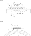
- FIG. 3B is a sectional view taken along 3B-3B of FIG. 3A .
- FIG. 4A is a perspective view showing a vibrator 3 and a magnet 7 that are separated in the L-mode guided wave sensor 10.
- FIG. 4B is a perspective view of the L-mode guided wave sensor 10.
- the L-mode guided wave sensor 10 is a device which uses an L-mode guided wave to inspect the inspection target 1.
- the L-mode guided wave sensor 10 comprises the vibrator 3, a coil 5, and the magnet 7.
- the vibrator 3 is made of a ferromagnetic material.
- the vibrator 3 is formed into a thin shape (thin plate shape). As a result, even if the vibrator 3 is small in size, the contact area between the vibrator 3 and the inspection target 1 can be increased so that the vibration of the vibrator 3 may be easily transmitted to the inspection target 1.
- a contact surface 3a of the vibrator 3 that contacts the inspection target 1 is a flat surface in the example of FIGS. 3A, 3B , 4A and 4B , but may be a curved surface instead. That is, when the vibrator 3 is formed into a thin shape (thin plate shape), the contact surface 3a of the vibrator 3 may be a curved surface that conforms to the curved shape of the surface of the inspection target 1 to which the contact surface 3a is attached. This permits the whole contact surface 3a of the vibrator 3 to tightly contact with the inspection target 1.
- the vibrator 3 may be attached to the inspection target 1 by proper means (a tape or an adhesive agent). However, when the inspection target 1 is made of a magnetic material, the vibrator 3 can be attached to the inspection target 1 by use of the magnetic force of the magnet 7 attached to the vibrator 3.
- the coil 5 is wound around the vibrator 3. An AC voltage is applied to the coil 5.
- the magnet 7 is attached to the vibrator 3.
- the magnet 7 has a south pole on one side in the axial direction of the coil 5 and has a north pole on the other side in the axial direction of the coil 5. It is sufficient for the magnet 7 to generate magnetic force that just holds the magnetic field in the ferromagnetic body (vibrator 3).
- the magnet 7 is a permanent magnet.
- the magnet 7 is attached to a surface 3b opposite to the contact surface 3a of the vibrator 3.
- the magnet 7 is preferably formed into a thin shape (thin plate shape) in the same manner as the vibrator 3. This permits the magnetic field generated by the magnet 7 to efficiently act in the vibrator 3.
- an attachment surface 7a of the magnet 7 attached to the surface 3b of the vibrator 3 preferably has a shape that conforms to the shape of the surface 3b of the vibrator 3. This permits the whole attachment surface 7a of the magnet 7 to tightly contact with the vibrator 3.
- the vibrator 3, the coil 5, and the magnet 7 are preferably combined together by proper combining means such as an adhesive agent.
- the L-mode guided wave sensor 10 further comprises an AC power supply 9, and a detector 11.
- the AC power supply 9 applies an AC voltage to the coil 5.
- the detector 11 is connected to the coil 5 so as to detect a voltage between both ends of the coil 5.
- the AC power supply 9 and the detector 11 are not shown.
- a proper switch is turned on in a state where the vibrator 3 having the coil 5 wound therearound and having the magnet 7 attached thereto is attached to the inspection target 1.
- the AC power supply 9 applies an AC voltage to the coil 5.
- the vibrator 3 is vibrated, so that an L-mode guided wave is generated in the inspection target 1, and the guided wave propagates through the inspection target 1.
- the guided wave thus propagated is reflected by a defective part of the inspection target 1 such as a scarred or corroded part (thickness reduced part), and then return to the position of the vibrator 3.
- a voltage generated between both ends of the coil 5 when the reflected wave reaches the position of the vibrator 3 is detected by the detector 11.
- FIGS. 6A and 6B are views taken along 6B-6B of FIG. 6A .
- the contact medium 13 may be a deformable solid such as an adhesive agent or a tape that combines the vibrator 3 and the inspection target 1, or may be liquid that fills a space between the vibrator 3 and the inspection target 1.
- the contact medium 13 preferably has a shape that can tightly contact with both of the vibrator 3 and the inspection target 1.
- the liquid is preferably held in the space between the vibrator 3 and the inspection target 1 by proper means (e.g. a sealing material bonded to the inspection target 1 around the space).
- the magnet 7 may be an electromagnet instead of the permanent magnet.
- the magnet 7 comprises a solid portion (preferably, a core portion made of a magnetic material), and a coil wound around the solid portion. A DC current is passed through the coil so that the magnetic field acts on the vibrator 3.
- the magnet 7 may be omitted. That is, the magnetic field generated in the ferromagnetic vibrator 3 by applying an AC voltage to the coil 5 can cause an L-mode guided wave to propagate through the inspection target 1. In this case, the magnet 7 may be omitted, and the other points are the same as the above description.
Landscapes
- Physics & Mathematics (AREA)
- Biochemistry (AREA)
- Health & Medical Sciences (AREA)
- Life Sciences & Earth Sciences (AREA)
- Chemical & Material Sciences (AREA)
- Analytical Chemistry (AREA)
- General Health & Medical Sciences (AREA)
- General Physics & Mathematics (AREA)
- Immunology (AREA)
- Pathology (AREA)
- Acoustics & Sound (AREA)
- Electromagnetism (AREA)
- Investigating Or Analyzing Materials By The Use Of Ultrasonic Waves (AREA)
Description
- The present invention relates to an L-mode guided wave sensor which uses a longitudinal mode (L-mode) guided wave to inspect an inspection target. The L-mode guided wave propagates through the inspection target while vibrating in its propagation direction. The frequency of the guided wave is, for example, 1 kHz to several hundred kHz (e.g. 32 kHz, 64 kHz, or 128 kHz).
- An L-mode guided wave is generated, for example, by a configuration in
FIG. 1 . InFIG. 1 , acoil 21 is wound around an inspection target 1 (pipe in the diagram), and amagnet 23 is attached to theinspection target 1. If an alternating current is passed through thecoil 21 in this state, an alternating-current magnetic field is generated. By use of magnetic force resulting from this alternating-current magnetic field and a magnetic field resulting from themagnet 23, theinspection target 1 which is a ferromagnetic body is vibrated by a magnetostrictive effect, and a guided wave which is a kind of a sound wave is thereby generated. The generated guided wave propagates through theinspection target 1 along its longitudinal direction. - A reflected wave of the guided wave is detected to inspect the soundness of the
inspection target 1. The guided wave is reflected as a reflected wave by a discontinuous part in theinspection target 1 and by a change in the cross-sectional area of theinspection target 1. By detecting the reflected wave, the soundness of theinspection target 1 is inspected. Regarding the soundness of theinspection target 1, for example, theinspection target 1 is inspected for defects such as a scarred or corroded part. - As compared with a sound wave used in general sound wave inspections, the guided wave attenuates less and enables the soundness of the
inspection target 1 to be inspected over a wide range of theinspection target 1. The sound wave used in general sound wave inspections has, for example, a high frequency of 5 MHz and a small wavelength of 0.6 mm, and accordingly easily attenuates. In contrast, the above-mentioned guided wave has, for example, a low frequency of several kHz to several ten kHz and a great wavelength of 100 mm, and accordingly does not easily attenuate. - For example, as prior art of the present application, there is:
-
Japanese Patent Application Laid-open Publication No. 2009-36516 - Further prior art documents are as follows:
US 2004/095137 A1 andUS 2007/090904 A1 relate to a method and an apparatus for evaluation of a pipe or a tube using a torsional wave.US 2004/095137 also discloses the generation of guide waves in a plate-like structure, by means of a sensor comprising a coil wound around an U-shaped ferromagnetic core placed on the inspected structure and an U-shaped magnet positioned over said coil/core arrangement. -
JP S57 165761 A DE 100 16 468 A1 relates to a run time measurement of acoustic pulse in a magnetoelastic screw.US 5 612 495 A relates to a non-destructive evaluation device.JP 4 131179 B2 - The inspection that uses an L-mode guided wave has the following problems (A) and (B).
-
- (A) A device is increased in size as below. In the configuration in
FIG. 1 , thecoil 21 is wound around theinspection target 1, so that thecoil 21 is also increased in dimensions when theinspection target 1 is large. Similarly, when theinspection target 1 is large, there is a need for thelarge magnet 23 having magnetic force that can hold the magnetic field in theinspection target 1 which is a ferromagnetic body. In this way, thecoil 21 and themagnet 23 are increased in dimensions. - (B) In order to generate an L-mode guided wave in the
inspection target 1, theinspection target 1 needs to be made of a ferromagnetic material. Accordingly, targets made of materials other than ferromagnetic materials cannot be inspected by an L-mode guided wave. - It is an object of the present invention to provide an L-mode guided wave sensor which can be reduced in size and which can also inspect a target made of a material other than ferromagnetic materials.
- In order to achieve the foregoing object, the present invention provides an L-mode guided wave sensor as defined in
claim 1. A method of using the L-mode guide wave sensor is defined in claim 4. - According to the present invention, a magnet is attached to the vibrator, and the magnet has a south pole on one side in the axial direction of the coil and has a north pole on the other side in the axial direction of the coil.
- According to the present invention described above, the vibrator attached to the inspection target is made of a ferromagnetic material, and the coil is wound around the vibrator, so that the dimensions of the coil does not need to be adjusted to the dimensions of the inspection target. Thus, the L-mode guided wave sensor can be reduced in size.
- Moreover, an alternating-current magnetic field generated by the coil is applied to the vibrator which is a ferromagnetic body different from the inspection target, and the vibrator is thereby vibrated. As a result, a guided wave is generated in the inspection target. Accordingly, a target made of a material other than ferromagnetic materials can also be inspected.
-
-
FIG. 1 shows a device conventionally used to generate an L-mode guided wave; -
FIG. 2A shows a state where an L-mode guided wave sensor according to an embodiment of the present invention has been attached to an inspection target; -
FIG. 2B is a sectional view taken along 2B-2B ofFIG. 2A ; -
FIG. 3A is a partial enlarged view of a part in the vicinity of the L-mode guided wave sensor inFIG. 2A ; -
FIG. 3B is a sectional view taken along 3B-3B ofFIG. 3A ; -
FIG. 4A is a perspective view showing a vibrator and a magnet that are separated in the L-mode guided wave sensor; -
FIG. 4B is a perspective view of the L-mode guided wave sensor; -
FIG. 5 illustrates multichannel guided waves produced by a plurality of L-mode guided wave sensors; -
FIG. 6A illustrates a contact medium provided between the vibrator and the inspection target; and -
FIG. 6B is a sectional view taken along 6B-6B ofFIG. 6A . - A preferred embodiment of the present invention will be described with reference to the drawings. The same reference numerals are attached to the common parts in the respective drawings, and the overlapping description will be omitted.
-
FIG. 2A shows a state where an L-mode guidedwave sensor 10 according to an embodiment of the present invention is attached to an inspection target.FIG. 2B is a sectional view taken along 2B-2B ofFIG. 2A . -
FIG. 3A is a partial enlarged view of a part in the vicinity of the L-mode guidedwave sensor 10 inFIG. 2A .FIG. 3B is a sectional view taken along 3B-3B ofFIG. 3A . -
FIG. 4A is a perspective view showing avibrator 3 and amagnet 7 that are separated in the L-mode guidedwave sensor 10.FIG. 4B is a perspective view of the L-mode guidedwave sensor 10. - The L-mode guided
wave sensor 10 is a device which uses an L-mode guided wave to inspect theinspection target 1. The L-mode guidedwave sensor 10 comprises thevibrator 3, acoil 5, and themagnet 7. - The
vibrator 3 is made of a ferromagnetic material. Preferably, as shown inFIGS. 3A and 3B , thevibrator 3 is formed into a thin shape (thin plate shape). As a result, even if thevibrator 3 is small in size, the contact area between thevibrator 3 and theinspection target 1 can be increased so that the vibration of thevibrator 3 may be easily transmitted to theinspection target 1. - A
contact surface 3a of thevibrator 3 that contacts theinspection target 1 is a flat surface in the example ofFIGS. 3A, 3B ,4A and 4B , but may be a curved surface instead. That is, when thevibrator 3 is formed into a thin shape (thin plate shape), thecontact surface 3a of thevibrator 3 may be a curved surface that conforms to the curved shape of the surface of theinspection target 1 to which thecontact surface 3a is attached. This permits thewhole contact surface 3a of thevibrator 3 to tightly contact with theinspection target 1. - The
vibrator 3 may be attached to theinspection target 1 by proper means (a tape or an adhesive agent). However, when theinspection target 1 is made of a magnetic material, thevibrator 3 can be attached to theinspection target 1 by use of the magnetic force of themagnet 7 attached to thevibrator 3. - The
coil 5 is wound around thevibrator 3. An AC voltage is applied to thecoil 5. - The
magnet 7 is attached to thevibrator 3. Themagnet 7 has a south pole on one side in the axial direction of thecoil 5 and has a north pole on the other side in the axial direction of thecoil 5. It is sufficient for themagnet 7 to generate magnetic force that just holds the magnetic field in the ferromagnetic body (vibrator 3). Themagnet 7 is a permanent magnet. Themagnet 7 is attached to asurface 3b opposite to thecontact surface 3a of thevibrator 3. - The
magnet 7 is preferably formed into a thin shape (thin plate shape) in the same manner as thevibrator 3. This permits the magnetic field generated by themagnet 7 to efficiently act in thevibrator 3. In this case, anattachment surface 7a of themagnet 7 attached to thesurface 3b of thevibrator 3 preferably has a shape that conforms to the shape of thesurface 3b of thevibrator 3. This permits thewhole attachment surface 7a of themagnet 7 to tightly contact with thevibrator 3. - The
vibrator 3, thecoil 5, and themagnet 7 are preferably combined together by proper combining means such as an adhesive agent. - As shown in
FIGS. 4A and 4B , the L-mode guidedwave sensor 10 further comprises anAC power supply 9, and adetector 11. TheAC power supply 9 applies an AC voltage to thecoil 5. Thedetector 11 is connected to thecoil 5 so as to detect a voltage between both ends of thecoil 5. InFIGS. 2A, 2B ,3A and 3B , theAC power supply 9 and thedetector 11 are not shown. - As shown in
FIGS. 2A, 2B ,3A and 3B , a proper switch is turned on in a state where thevibrator 3 having thecoil 5 wound therearound and having themagnet 7 attached thereto is attached to theinspection target 1. Thereby, theAC power supply 9 applies an AC voltage to thecoil 5. As a result, thevibrator 3 is vibrated, so that an L-mode guided wave is generated in theinspection target 1, and the guided wave propagates through theinspection target 1. The guided wave thus propagated is reflected by a defective part of theinspection target 1 such as a scarred or corroded part (thickness reduced part), and then return to the position of thevibrator 3. A voltage generated between both ends of thecoil 5 when the reflected wave reaches the position of thevibrator 3 is detected by thedetector 11. - The following advantageous effects (1) to (7) are obtained by the L-mode guided
wave sensor 10 according to the present embodiment described above. -
- (1) The
vibrator 3 attached to theinspection target 1 is made of a ferromagnetic material, and thecoil 5 is wound around thisvibrator 3, so that the dimensions of thecoil 5 does not need to be adjusted to the dimensions of theinspection target 1. Thus, the L-mode guidedwave sensor 10 can be considerably reduced in size as compared withFIG. 1 . - (2) The
vibrator 3 is vibrated by applying an alternating-current magnetic field generated by thecoil 5 to thevibrator 3 which is a ferromagnetic body different from theinspection target 1, and a guided wave is thereby generated in theinspection target 1. Accordingly, atarget 1 made of materials other than ferromagnetic materials can also be inspected. - (3) The magnetic force of the
magnet 7 can be much less than in the prior art, so that themagnet 7 can be reduced in size. The prior art requires a large magnet having magnetic force that can hold the magnetic field in theinspection target 1 which is a ferromagnetic body, as shown inFIG. 1 . In contrast, the present embodiment requires themagnet 7 having magnetic force that just holds the magnetic field in the small vibrator 3 (ferromagnetic body). Thus, themagnet 7 can be reduced in size. - (4) The
vibrator 3, thecoil 5, and themagnet 7 are combined together by proper combining means such as an adhesive agent, so that thevibrator 3, thecoil 5, and themagnet 7 become easy to handle. In this case, thevibrator 3, thecoil 5, and themagnet 7 that are combined together can serve as the L-mode guidedwave sensor 10 in which thecoil 5 can be connected to theAC power supply 9 and thedetector 11. This L-mode guidedwave sensor 10 can be sold as a product separated from theAC power supply 9 and the detector. - (5) As the L-mode guided
wave sensor 10 can be reduced in size, it is possible to adapt to various shapes of the inspection targets 1 as follows. Conventionally, theinspection target 1 needs to have a shape (e.g. cylindrical shape) that allows the winding of a coil necessary to generate a guided wave. In contrast, according to the present embodiment, it suffices that thesmall vibrator 3 is attached to theinspection target 1. For this reason, according to the present invention, a shape of atarget 1 to be inspected is not restricted, and targets 1 having various shapes (e.g. a large flat plate) can be inspected. - (6) As the L-mode guided
wave sensor 10 can be reduced in size, the L-mode guidedwave sensor 10 can be attached to even a narrow portion of theinspection target 1. - (7) As the L-mode guided
wave sensor 10 can be reduced in size, a plurality of L-mode guidedwave sensors 10 can be arranged on theinspection target 1 and attached to theinspection target 1, as shown inFIG. 5 . This enables generation of multichannel L-mode guided waves (channels CH1 to CH4 inFIG. 5 ). InFIG. 5 , theAC power supply 9 and thedetector 11 of each L-mode guidedwave sensor 10 are not shown. - It should be understood that the present invention is not limited to the embodiment described above, and various modifications can be made without departing from the scope of the invention, as defined by the claims. For example,
Modification 1 described below may be employed. - Although the
vibrator 3 is directly attached to theinspection target 1 in the example ofFIGS. 3A and 3B , thevibrator 3 may be attached to theinspection target 1 via acontact medium 13, as shown inFIGS. 6A and 6B. FIG. 6A corresponds toFIG. 3A , and snows a case in which thecontact medium 13 is provided.FIG. 6B is a sectional view taken along 6B-6B ofFIG. 6A . - Even if a large contact area cannot be secured between the
vibrator 3 and theinspection target 1, thecontact medium 13 improves vibration transmission between thevibrator 3 and theinspection target 1. Thecontact medium 13 may be a deformable solid such as an adhesive agent or a tape that combines thevibrator 3 and theinspection target 1, or may be liquid that fills a space between thevibrator 3 and theinspection target 1. When a solid is used as thecontact medium 13, thecontact medium 13 preferably has a shape that can tightly contact with both of thevibrator 3 and theinspection target 1. When liquid is used as thecontact medium 13, the liquid is preferably held in the space between thevibrator 3 and theinspection target 1 by proper means (e.g. a sealing material bonded to theinspection target 1 around the space). - The
magnet 7 may be an electromagnet instead of the permanent magnet. In this case, themagnet 7 comprises a solid portion (preferably, a core portion made of a magnetic material), and a coil wound around the solid portion. A DC current is passed through the coil so that the magnetic field acts on thevibrator 3. - The
magnet 7 may be omitted. That is, the magnetic field generated in theferromagnetic vibrator 3 by applying an AC voltage to thecoil 5 can cause an L-mode guided wave to propagate through theinspection target 1. In this case, themagnet 7 may be omitted, and the other points are the same as the above description. - 1: inspection target, 3: vibrator, 3a: contact surface of the vibrator, 5: coil, 7: magnet, 9: AC power supply, 10: L-mode guided wave sensor, 11: detector, 13: contact medium
Claims (4)
- An L-mode guided wave sensor configured to inspect an inspection target (1) by using an L-mode guided wave, comprising:a plate-shaped vibrator (3) which is attachable to the inspection target (1);a coil (5) to which an AC voltage is applicable; anda permanent magnet (7) attached to the plate-shaped vibrator (3),wherein the permanent magnet (7) has a south pole (S) on one side in an axial direction of the coil (5) and has a north pole (N) on the other side in the axial direction of the coil (5),the plate-shaped vibrator (3) includes a contact surface (3a) that contacts the inspection target (1) and a surface (3b) opposite to the contact surface (3a),the permanent magnet (7) is attached to the surface (3b) of the plate-shaped vibrator (3),the plate-shaped vibrator (3) is made of a ferromagnetic material andthe coil (5) is wound around the plate-shaped vibrator (3) such that an alternating-current magnetic field generated by the coil is applied to cause the plate-shaped vibrator (3) to vibrate to generate an L-mode guided wave in the inspection target (1).
- The L-mode guided wave sensor according to claim 1, further comprising a contact medium (13), and the plate-shaped vibrator (3) is attachable to the inspection target (1) via the contact medium (13).
- The L-mode guided wave sensor according to claim 1 or 2, further comprising:an AC power supply (9) configured to apply the AC voltage to the coil (5); anda detector (11), wherein the detector (11) is connected to the coil (5) so as to detect a voltage between both ends of the coil (5).
- A method of using the L-mode guided wave sensor (10) according to any one of claims 1 to 3,
wherein
in a state where the plate-shaped vibrator (3) is attached to an outer surface of the inspection target (1), the AC voltage is applied to the coil (5), so that vibration of the plate-shaped vibrator (3) is transmitted to the inspection target (1) to generate an L-mode guided wave in the inspection target (1).
Applications Claiming Priority (2)
| Application Number | Priority Date | Filing Date | Title |
|---|---|---|---|
| JP2010101817A JP4568377B1 (en) | 2010-04-27 | 2010-04-27 | L-mode guided wave sensor and its usage |
| PCT/JP2010/057934 WO2011135732A1 (en) | 2010-04-27 | 2010-05-11 | L-mode guided wave sensor |
Publications (3)
| Publication Number | Publication Date |
|---|---|
| EP2565642A1 EP2565642A1 (en) | 2013-03-06 |
| EP2565642A4 EP2565642A4 (en) | 2016-12-21 |
| EP2565642B1 true EP2565642B1 (en) | 2022-03-09 |
Family
ID=43098841
Family Applications (1)
| Application Number | Title | Priority Date | Filing Date |
|---|---|---|---|
| EP10850747.6A Not-in-force EP2565642B1 (en) | 2010-04-27 | 2010-05-11 | L-mode guided wave sensor |
Country Status (4)
| Country | Link |
|---|---|
| US (1) | US9551691B2 (en) |
| EP (1) | EP2565642B1 (en) |
| JP (1) | JP4568377B1 (en) |
| WO (1) | WO2011135732A1 (en) |
Families Citing this family (3)
| Publication number | Priority date | Publication date | Assignee | Title |
|---|---|---|---|---|
| FR2999677B1 (en) * | 2012-12-18 | 2015-01-16 | V & M France | ELEMENT OF DRIVING TEAM |
| US10466206B2 (en) * | 2016-12-12 | 2019-11-05 | Southwest Research Institute | Non destructive magnetostrictive testing with unidirectional guided waves generated by ferromagnetic strip sensor |
| US11283486B1 (en) * | 2018-06-25 | 2022-03-22 | Hrl Laboratories, Llc | Mechanically actuated magnetostrictive transmitter |
Citations (1)
| Publication number | Priority date | Publication date | Assignee | Title |
|---|---|---|---|---|
| US4127035A (en) * | 1977-09-02 | 1978-11-28 | Rockwell International Corporation | Electromagnetic transducer |
Family Cites Families (12)
| Publication number | Priority date | Publication date | Assignee | Title |
|---|---|---|---|---|
| US3512400A (en) * | 1967-04-13 | 1970-05-19 | Panametrics | Ultrasonic testing method |
| US4296486A (en) * | 1980-01-24 | 1981-10-20 | Rockwell International Corporation | Shielded electromagnetic acoustic transducers |
| JPS57165761A (en) * | 1981-04-03 | 1982-10-12 | Nippon Kokan Kk <Nkk> | Transducer for electro-magnetic ultrasonic wave |
| GB2124764B (en) * | 1982-08-03 | 1986-01-08 | Atomic Energy Authority Uk | Ice detector |
| US4522071A (en) * | 1983-07-28 | 1985-06-11 | The United States Of America As Represented By The United States Department Of Energy | Method and apparatus for measuring stress |
| JPH08334431A (en) * | 1995-06-09 | 1996-12-17 | Mitsubishi Electric Corp | Non-destructive inspection device |
| US6917196B2 (en) * | 1999-03-17 | 2005-07-12 | Southwest Research Institute | Method and apparatus generating and detecting torsional wave inspection of pipes or tubes |
| DE10016468C2 (en) * | 2000-04-01 | 2002-03-14 | Daimler Chrysler Ag | Method and device for measuring the transit time of sound pulses in a magnetoelastic workpiece |
| JP4131179B2 (en) * | 2003-03-11 | 2008-08-13 | セイコーエプソン株式会社 | Giant magnetostrictive broadband ultrasonic generator |
| KR100677920B1 (en) * | 2005-10-20 | 2007-02-05 | 재단법인서울대학교산학협력재단 | Method for generating and measuring torsional waves in rods, shafts or piping members using magnetostrictive effects, magnetostrictive transducers using them, and structural diagnostic devices |
| JP2009036516A (en) | 2007-07-31 | 2009-02-19 | Hitachi-Ge Nuclear Energy Ltd | Nondestructive inspection apparatus and nondestructive inspection method using guide wave |
| JP4508266B2 (en) * | 2008-05-12 | 2010-07-21 | セイコーエプソン株式会社 | Coil unit and electronic device using the same |
-
2010
- 2010-04-27 JP JP2010101817A patent/JP4568377B1/en active Active
- 2010-05-11 EP EP10850747.6A patent/EP2565642B1/en not_active Not-in-force
- 2010-05-11 WO PCT/JP2010/057934 patent/WO2011135732A1/en not_active Ceased
- 2010-05-11 US US13/639,466 patent/US9551691B2/en not_active Expired - Fee Related
Patent Citations (1)
| Publication number | Priority date | Publication date | Assignee | Title |
|---|---|---|---|---|
| US4127035A (en) * | 1977-09-02 | 1978-11-28 | Rockwell International Corporation | Electromagnetic transducer |
Also Published As
| Publication number | Publication date |
|---|---|
| JP4568377B1 (en) | 2010-10-27 |
| WO2011135732A1 (en) | 2011-11-03 |
| US9551691B2 (en) | 2017-01-24 |
| EP2565642A1 (en) | 2013-03-06 |
| US20130036822A1 (en) | 2013-02-14 |
| JP2011232135A (en) | 2011-11-17 |
| EP2565642A4 (en) | 2016-12-21 |
Similar Documents
| Publication | Publication Date | Title |
|---|---|---|
| US9310339B2 (en) | Hybrid inspection system and method employing both air-coupled and liquid-coupled transducers | |
| Hirao et al. | EMATs for science and industry: noncontacting ultrasonic measurements | |
| CN102474690B (en) | Contact Horizontal Shear Guided Wave Magnetostrictive Transducer | |
| US20100192693A1 (en) | Acoustic transducer assembly | |
| CN102662003B (en) | Omni-directional shear horizontal (SH) guided wave electromagnetic ultrasonic transducer | |
| KR100561215B1 (en) | Magnetostrictive transducers capable of generating and measuring elastic ultrasonic waves and structural diagnostic devices using them | |
| US10481131B2 (en) | Ultrasonic test system, ultrasonic test method and method of manufacturing aircraft part | |
| JP6362533B2 (en) | Residual stress evaluation method and residual stress evaluation apparatus | |
| Ma et al. | Excitation and detection of shear horizontal waves with electromagnetic acoustic transducers for nondestructive testing of plates | |
| CN104198594A (en) | Multiple-main-frequency combined torsional-mode electromagnetic acoustic array sensor | |
| KR100573736B1 (en) | Transducer capable of generating and measuring torsional waves, and an abnormal diagnosis device and method using the same | |
| CN107091880B (en) | A kind of metal-base composites unsticking detection method | |
| US20160299106A1 (en) | Systems and methods for using flexural modes in non-destructive testing and inspection | |
| US10641741B2 (en) | High-temperature magnetostrictive guided wave pipe inspection system | |
| US8286492B2 (en) | Mode decomposition of sound waves using amplitude matching | |
| KR20200028022A (en) | Improved guide par thermography inspection systems and methods of using them | |
| KR101061226B1 (en) | Magnetostrictive transducer module for induction ultrasonic conversion | |
| US9465011B2 (en) | Flexible magnetostrictive probe having sensor elements without permanent magnets | |
| CN104076094A (en) | Ultrasonic transduction probe for exciting and receiving ultrasonic horizontal shear guide wave | |
| KR101877769B1 (en) | Apparatus for hybrid multi-frequency ultrasound phased array imaging | |
| US9170239B2 (en) | Magnetostrictive sensor having crimped magnetostrictive strip for high temperature operation | |
| US9551691B2 (en) | L-mode guided wave sensor | |
| CN206489119U (en) | Type multimode electromagnetic ultrasonic testing system and electromagnetic ultrasonic transducer | |
| US11385115B2 (en) | Device for inspecting clamping means by ultrasounds and method implementing the device | |
| KR101587740B1 (en) | Contact type magnetostrictive guided-wave transducer module |
Legal Events
| Date | Code | Title | Description |
|---|---|---|---|
| PUAI | Public reference made under article 153(3) epc to a published international application that has entered the european phase |
Free format text: ORIGINAL CODE: 0009012 |
|
| 17P | Request for examination filed |
Effective date: 20121029 |
|
| AK | Designated contracting states |
Kind code of ref document: A1 Designated state(s): AL AT BE BG CH CY CZ DE DK EE ES FI FR GB GR HR HU IE IS IT LI LT LU LV MC MK MT NL NO PL PT RO SE SI SK SM TR |
|
| DAX | Request for extension of the european patent (deleted) | ||
| RAP1 | Party data changed (applicant data changed or rights of an application transferred) |
Owner name: IHI INSPECTION AND INSTRUMENTATION CO., LTD. |
|
| RAP1 | Party data changed (applicant data changed or rights of an application transferred) |
Owner name: IHI INSPECTION AND INSTRUMENTATION CO., LTD. |
|
| RA4 | Supplementary search report drawn up and despatched (corrected) |
Effective date: 20161122 |
|
| RIC1 | Information provided on ipc code assigned before grant |
Ipc: G01N 29/04 20060101AFI20161116BHEP Ipc: G01N 29/24 20060101ALI20161116BHEP |
|
| STAA | Information on the status of an ep patent application or granted ep patent |
Free format text: STATUS: EXAMINATION IS IN PROGRESS |
|
| 17Q | First examination report despatched |
Effective date: 20200122 |
|
| GRAP | Despatch of communication of intention to grant a patent |
Free format text: ORIGINAL CODE: EPIDOSNIGR1 |
|
| STAA | Information on the status of an ep patent application or granted ep patent |
Free format text: STATUS: GRANT OF PATENT IS INTENDED |
|
| GRAJ | Information related to disapproval of communication of intention to grant by the applicant or resumption of examination proceedings by the epo deleted |
Free format text: ORIGINAL CODE: EPIDOSDIGR1 |
|
| GRAP | Despatch of communication of intention to grant a patent |
Free format text: ORIGINAL CODE: EPIDOSNIGR1 |
|
| INTG | Intention to grant announced |
Effective date: 20211011 |
|
| INTG | Intention to grant announced |
Effective date: 20211027 |
|
| GRAS | Grant fee paid |
Free format text: ORIGINAL CODE: EPIDOSNIGR3 |
|
| GRAA | (expected) grant |
Free format text: ORIGINAL CODE: 0009210 |
|
| STAA | Information on the status of an ep patent application or granted ep patent |
Free format text: STATUS: THE PATENT HAS BEEN GRANTED |
|
| AK | Designated contracting states |
Kind code of ref document: B1 Designated state(s): AL AT BE BG CH CY CZ DE DK EE ES FI FR GB GR HR HU IE IS IT LI LT LU LV MC MK MT NL NO PL PT RO SE SI SK SM TR |
|
| REG | Reference to a national code |
Ref country code: GB Ref legal event code: FG4D |
|
| REG | Reference to a national code |
Ref country code: CH Ref legal event code: EP Ref country code: AT Ref legal event code: REF Ref document number: 1474577 Country of ref document: AT Kind code of ref document: T Effective date: 20220315 |
|
| REG | Reference to a national code |
Ref country code: IE Ref legal event code: FG4D |
|
| REG | Reference to a national code |
Ref country code: DE Ref legal event code: R096 Ref document number: 602010068098 Country of ref document: DE |
|
| REG | Reference to a national code |
Ref country code: LT Ref legal event code: MG9D |
|
| REG | Reference to a national code |
Ref country code: NL Ref legal event code: MP Effective date: 20220309 |
|
| PG25 | Lapsed in a contracting state [announced via postgrant information from national office to epo] |
Ref country code: SE Free format text: LAPSE BECAUSE OF FAILURE TO SUBMIT A TRANSLATION OF THE DESCRIPTION OR TO PAY THE FEE WITHIN THE PRESCRIBED TIME-LIMIT Effective date: 20220309 Ref country code: NO Free format text: LAPSE BECAUSE OF FAILURE TO SUBMIT A TRANSLATION OF THE DESCRIPTION OR TO PAY THE FEE WITHIN THE PRESCRIBED TIME-LIMIT Effective date: 20220609 Ref country code: LT Free format text: LAPSE BECAUSE OF FAILURE TO SUBMIT A TRANSLATION OF THE DESCRIPTION OR TO PAY THE FEE WITHIN THE PRESCRIBED TIME-LIMIT Effective date: 20220309 Ref country code: HR Free format text: LAPSE BECAUSE OF FAILURE TO SUBMIT A TRANSLATION OF THE DESCRIPTION OR TO PAY THE FEE WITHIN THE PRESCRIBED TIME-LIMIT Effective date: 20220309 Ref country code: BG Free format text: LAPSE BECAUSE OF FAILURE TO SUBMIT A TRANSLATION OF THE DESCRIPTION OR TO PAY THE FEE WITHIN THE PRESCRIBED TIME-LIMIT Effective date: 20220609 |
|
| REG | Reference to a national code |
Ref country code: AT Ref legal event code: MK05 Ref document number: 1474577 Country of ref document: AT Kind code of ref document: T Effective date: 20220309 |
|
| PG25 | Lapsed in a contracting state [announced via postgrant information from national office to epo] |
Ref country code: LV Free format text: LAPSE BECAUSE OF FAILURE TO SUBMIT A TRANSLATION OF THE DESCRIPTION OR TO PAY THE FEE WITHIN THE PRESCRIBED TIME-LIMIT Effective date: 20220309 Ref country code: GR Free format text: LAPSE BECAUSE OF FAILURE TO SUBMIT A TRANSLATION OF THE DESCRIPTION OR TO PAY THE FEE WITHIN THE PRESCRIBED TIME-LIMIT Effective date: 20220610 Ref country code: FI Free format text: LAPSE BECAUSE OF FAILURE TO SUBMIT A TRANSLATION OF THE DESCRIPTION OR TO PAY THE FEE WITHIN THE PRESCRIBED TIME-LIMIT Effective date: 20220309 |
|
| PG25 | Lapsed in a contracting state [announced via postgrant information from national office to epo] |
Ref country code: NL Free format text: LAPSE BECAUSE OF FAILURE TO SUBMIT A TRANSLATION OF THE DESCRIPTION OR TO PAY THE FEE WITHIN THE PRESCRIBED TIME-LIMIT Effective date: 20220309 |
|
| PG25 | Lapsed in a contracting state [announced via postgrant information from national office to epo] |
Ref country code: SM Free format text: LAPSE BECAUSE OF FAILURE TO SUBMIT A TRANSLATION OF THE DESCRIPTION OR TO PAY THE FEE WITHIN THE PRESCRIBED TIME-LIMIT Effective date: 20220309 Ref country code: SK Free format text: LAPSE BECAUSE OF FAILURE TO SUBMIT A TRANSLATION OF THE DESCRIPTION OR TO PAY THE FEE WITHIN THE PRESCRIBED TIME-LIMIT Effective date: 20220309 Ref country code: RO Free format text: LAPSE BECAUSE OF FAILURE TO SUBMIT A TRANSLATION OF THE DESCRIPTION OR TO PAY THE FEE WITHIN THE PRESCRIBED TIME-LIMIT Effective date: 20220309 Ref country code: PT Free format text: LAPSE BECAUSE OF FAILURE TO SUBMIT A TRANSLATION OF THE DESCRIPTION OR TO PAY THE FEE WITHIN THE PRESCRIBED TIME-LIMIT Effective date: 20220711 Ref country code: ES Free format text: LAPSE BECAUSE OF FAILURE TO SUBMIT A TRANSLATION OF THE DESCRIPTION OR TO PAY THE FEE WITHIN THE PRESCRIBED TIME-LIMIT Effective date: 20220309 Ref country code: EE Free format text: LAPSE BECAUSE OF FAILURE TO SUBMIT A TRANSLATION OF THE DESCRIPTION OR TO PAY THE FEE WITHIN THE PRESCRIBED TIME-LIMIT Effective date: 20220309 Ref country code: CZ Free format text: LAPSE BECAUSE OF FAILURE TO SUBMIT A TRANSLATION OF THE DESCRIPTION OR TO PAY THE FEE WITHIN THE PRESCRIBED TIME-LIMIT Effective date: 20220309 Ref country code: AT Free format text: LAPSE BECAUSE OF FAILURE TO SUBMIT A TRANSLATION OF THE DESCRIPTION OR TO PAY THE FEE WITHIN THE PRESCRIBED TIME-LIMIT Effective date: 20220309 |
|
| PG25 | Lapsed in a contracting state [announced via postgrant information from national office to epo] |
Ref country code: PL Free format text: LAPSE BECAUSE OF FAILURE TO SUBMIT A TRANSLATION OF THE DESCRIPTION OR TO PAY THE FEE WITHIN THE PRESCRIBED TIME-LIMIT Effective date: 20220309 Ref country code: IS Free format text: LAPSE BECAUSE OF FAILURE TO SUBMIT A TRANSLATION OF THE DESCRIPTION OR TO PAY THE FEE WITHIN THE PRESCRIBED TIME-LIMIT Effective date: 20220709 Ref country code: AL Free format text: LAPSE BECAUSE OF FAILURE TO SUBMIT A TRANSLATION OF THE DESCRIPTION OR TO PAY THE FEE WITHIN THE PRESCRIBED TIME-LIMIT Effective date: 20220309 |
|
| REG | Reference to a national code |
Ref country code: DE Ref legal event code: R097 Ref document number: 602010068098 Country of ref document: DE |
|
| REG | Reference to a national code |
Ref country code: CH Ref legal event code: PL |
|
| PLBE | No opposition filed within time limit |
Free format text: ORIGINAL CODE: 0009261 |
|
| STAA | Information on the status of an ep patent application or granted ep patent |
Free format text: STATUS: NO OPPOSITION FILED WITHIN TIME LIMIT |
|
| REG | Reference to a national code |
Ref country code: BE Ref legal event code: MM Effective date: 20220531 |
|
| PG25 | Lapsed in a contracting state [announced via postgrant information from national office to epo] |
Ref country code: MC Free format text: LAPSE BECAUSE OF FAILURE TO SUBMIT A TRANSLATION OF THE DESCRIPTION OR TO PAY THE FEE WITHIN THE PRESCRIBED TIME-LIMIT Effective date: 20220309 Ref country code: LU Free format text: LAPSE BECAUSE OF NON-PAYMENT OF DUE FEES Effective date: 20220511 Ref country code: LI Free format text: LAPSE BECAUSE OF NON-PAYMENT OF DUE FEES Effective date: 20220531 Ref country code: DK Free format text: LAPSE BECAUSE OF FAILURE TO SUBMIT A TRANSLATION OF THE DESCRIPTION OR TO PAY THE FEE WITHIN THE PRESCRIBED TIME-LIMIT Effective date: 20220309 Ref country code: CH Free format text: LAPSE BECAUSE OF NON-PAYMENT OF DUE FEES Effective date: 20220531 |
|
| 26N | No opposition filed |
Effective date: 20221212 |
|
| PG25 | Lapsed in a contracting state [announced via postgrant information from national office to epo] |
Ref country code: SI Free format text: LAPSE BECAUSE OF FAILURE TO SUBMIT A TRANSLATION OF THE DESCRIPTION OR TO PAY THE FEE WITHIN THE PRESCRIBED TIME-LIMIT Effective date: 20220309 |
|
| PG25 | Lapsed in a contracting state [announced via postgrant information from national office to epo] |
Ref country code: IE Free format text: LAPSE BECAUSE OF NON-PAYMENT OF DUE FEES Effective date: 20220511 |
|
| PG25 | Lapsed in a contracting state [announced via postgrant information from national office to epo] |
Ref country code: BE Free format text: LAPSE BECAUSE OF NON-PAYMENT OF DUE FEES Effective date: 20220531 |
|
| PG25 | Lapsed in a contracting state [announced via postgrant information from national office to epo] |
Ref country code: IT Free format text: LAPSE BECAUSE OF FAILURE TO SUBMIT A TRANSLATION OF THE DESCRIPTION OR TO PAY THE FEE WITHIN THE PRESCRIBED TIME-LIMIT Effective date: 20220309 |
|
| PGFP | Annual fee paid to national office [announced via postgrant information from national office to epo] |
Ref country code: FR Payment date: 20230523 Year of fee payment: 14 Ref country code: DE Payment date: 20230526 Year of fee payment: 14 |
|
| PGFP | Annual fee paid to national office [announced via postgrant information from national office to epo] |
Ref country code: GB Payment date: 20230526 Year of fee payment: 14 |
|
| PG25 | Lapsed in a contracting state [announced via postgrant information from national office to epo] |
Ref country code: HU Free format text: LAPSE BECAUSE OF FAILURE TO SUBMIT A TRANSLATION OF THE DESCRIPTION OR TO PAY THE FEE WITHIN THE PRESCRIBED TIME-LIMIT; INVALID AB INITIO Effective date: 20100511 |
|
| PG25 | Lapsed in a contracting state [announced via postgrant information from national office to epo] |
Ref country code: MK Free format text: LAPSE BECAUSE OF FAILURE TO SUBMIT A TRANSLATION OF THE DESCRIPTION OR TO PAY THE FEE WITHIN THE PRESCRIBED TIME-LIMIT Effective date: 20220309 Ref country code: CY Free format text: LAPSE BECAUSE OF FAILURE TO SUBMIT A TRANSLATION OF THE DESCRIPTION OR TO PAY THE FEE WITHIN THE PRESCRIBED TIME-LIMIT Effective date: 20220309 |
|
| PG25 | Lapsed in a contracting state [announced via postgrant information from national office to epo] |
Ref country code: TR Free format text: LAPSE BECAUSE OF FAILURE TO SUBMIT A TRANSLATION OF THE DESCRIPTION OR TO PAY THE FEE WITHIN THE PRESCRIBED TIME-LIMIT Effective date: 20220309 |
|
| PG25 | Lapsed in a contracting state [announced via postgrant information from national office to epo] |
Ref country code: MT Free format text: LAPSE BECAUSE OF FAILURE TO SUBMIT A TRANSLATION OF THE DESCRIPTION OR TO PAY THE FEE WITHIN THE PRESCRIBED TIME-LIMIT Effective date: 20220309 |
|
| REG | Reference to a national code |
Ref country code: DE Ref legal event code: R119 Ref document number: 602010068098 Country of ref document: DE |
|
| GBPC | Gb: european patent ceased through non-payment of renewal fee |
Effective date: 20240511 |
|
| PG25 | Lapsed in a contracting state [announced via postgrant information from national office to epo] |
Ref country code: DE Free format text: LAPSE BECAUSE OF NON-PAYMENT OF DUE FEES Effective date: 20241203 |
|
| PG25 | Lapsed in a contracting state [announced via postgrant information from national office to epo] |
Ref country code: FR Free format text: LAPSE BECAUSE OF NON-PAYMENT OF DUE FEES Effective date: 20240531 |
|
| PG25 | Lapsed in a contracting state [announced via postgrant information from national office to epo] |
Ref country code: GB Free format text: LAPSE BECAUSE OF NON-PAYMENT OF DUE FEES Effective date: 20240511 |