EP2565612A1 - Contact force measurement method and contact force measurement device - Google Patents
Contact force measurement method and contact force measurement device Download PDFInfo
- Publication number
- EP2565612A1 EP2565612A1 EP11774805A EP11774805A EP2565612A1 EP 2565612 A1 EP2565612 A1 EP 2565612A1 EP 11774805 A EP11774805 A EP 11774805A EP 11774805 A EP11774805 A EP 11774805A EP 2565612 A1 EP2565612 A1 EP 2565612A1
- Authority
- EP
- European Patent Office
- Prior art keywords
- ship
- pantograph
- marker
- shaped body
- contact force
- Prior art date
- Legal status (The legal status is an assumption and is not a legal conclusion. Google has not performed a legal analysis and makes no representation as to the accuracy of the status listed.)
- Granted
Links
Images


Classifications
-
- G—PHYSICS
- G01—MEASURING; TESTING
- G01L—MEASURING FORCE, STRESS, TORQUE, WORK, MECHANICAL POWER, MECHANICAL EFFICIENCY, OR FLUID PRESSURE
- G01L5/00—Apparatus for, or methods of, measuring force, work, mechanical power, or torque, specially adapted for specific purposes
-
- G—PHYSICS
- G01—MEASURING; TESTING
- G01L—MEASURING FORCE, STRESS, TORQUE, WORK, MECHANICAL POWER, MECHANICAL EFFICIENCY, OR FLUID PRESSURE
- G01L5/00—Apparatus for, or methods of, measuring force, work, mechanical power, or torque, specially adapted for specific purposes
- G01L5/0057—Apparatus for, or methods of, measuring force, work, mechanical power, or torque, specially adapted for specific purposes measuring forces due to spring-shaped elements
-
- B—PERFORMING OPERATIONS; TRANSPORTING
- B60—VEHICLES IN GENERAL
- B60M—POWER SUPPLY LINES, AND DEVICES ALONG RAILS, FOR ELECTRICALLY- PROPELLED VEHICLES
- B60M1/00—Power supply lines for contact with collector on vehicle
- B60M1/12—Trolley lines; Accessories therefor
- B60M1/28—Manufacturing or repairing trolley lines
-
- G—PHYSICS
- G01—MEASURING; TESTING
- G01B—MEASURING LENGTH, THICKNESS OR SIMILAR LINEAR DIMENSIONS; MEASURING ANGLES; MEASURING AREAS; MEASURING IRREGULARITIES OF SURFACES OR CONTOURS
- G01B11/00—Measuring arrangements characterised by the use of optical techniques
-
- G—PHYSICS
- G01—MEASURING; TESTING
- G01L—MEASURING FORCE, STRESS, TORQUE, WORK, MECHANICAL POWER, MECHANICAL EFFICIENCY, OR FLUID PRESSURE
- G01L1/00—Measuring force or stress, in general
- G01L1/04—Measuring force or stress, in general by measuring elastic deformation of gauges, e.g. of springs
- G01L1/044—Measuring force or stress, in general by measuring elastic deformation of gauges, e.g. of springs of leaf springs
-
- B—PERFORMING OPERATIONS; TRANSPORTING
- B60—VEHICLES IN GENERAL
- B60L—PROPULSION OF ELECTRICALLY-PROPELLED VEHICLES; SUPPLYING ELECTRIC POWER FOR AUXILIARY EQUIPMENT OF ELECTRICALLY-PROPELLED VEHICLES; ELECTRODYNAMIC BRAKE SYSTEMS FOR VEHICLES IN GENERAL; MAGNETIC SUSPENSION OR LEVITATION FOR VEHICLES; MONITORING OPERATING VARIABLES OF ELECTRICALLY-PROPELLED VEHICLES; ELECTRIC SAFETY DEVICES FOR ELECTRICALLY-PROPELLED VEHICLES
- B60L5/00—Current collectors for power supply lines of electrically-propelled vehicles
- B60L5/18—Current collectors for power supply lines of electrically-propelled vehicles using bow-type collectors in contact with trolley wire
- B60L5/20—Details of contact bow
Definitions
- the present invention relates to a contact force measurement method and a contact force measurement device.
- an electric collector device mounted on a roof of a train such as a pantograph and an overhead wire contact with each other so that electric power is supplied.
- a contact force is produced between the pantograph and the overhead wire.
- the pantograph would be released from the overhead wire.
- a discharge phenomenon called as "ark” is happened between the released pantograph and the overhead wire. If such an ark is happened, the overhead wire is worn away.
- the contact force is not varied so much.
- Patent document 1 discloses that a frequency response function of a pantograph depending on a variation of contact force is previously measured and the contact force is calculated by convolution integrate with time series response of a moving pantograph and the frequency response function.
- Patent document 2 as described below discloses a method for measuring contact force wherein sensors such as an acceleration meter, a strain gauge and so on are arranged at a pantograph.
- the contact force of the pantograph is obtained by measuring a spring reaction force and an inert force of the pantograph.
- Patent document 3 as described below discloses a method for measuring contact force of a pantograph wherein two pairs of upper and lower lighting sources such as LED are provided at a spring portion of the pantograph.
- the contact force of the pantograph is obtained by processing images of the light sources captured by a CCD camera and a relative displacement of the spring portion is detected. Thus, by detecting an elasticity of the spring, the contact force of the pantograph can be obtained.
- Patent document 4 discloses a method for measuring a contact force of the pantograph wherein line sensor cameras (hereinafter, it is referred as "line sensors”) are provided at a position above a roof portion of the pantograph and imaged of a spring portion of the pantograph is captured. By detecting a relative displacement by processing captured images, the elasticity of the spring is detected. Thus, the contact force of the pantograph is obtained.
- line sensors line sensor cameras
- the patent document 4 does not disclose how captured images are processed in detail.
- Patent document 5 discloses a method for measuring a displacement of a pantograph wherein a striped marker of which some parts are high light reflective regions and the remained parts are low reflective regions is mounted at the pantograph and line sensors are arranged at a roof portion of a train body in order to photographs images of the marker along a vertical direction. By detecting a position of the marker with a pattern matching, the displacement of the pantograph is detected.
- time series images recorded per every time unit by scanning along a vertical direction are approximately compared with a marker pattern corresponding to striped design in order to judge whether the images are coincident with the marker pattern or similar to the marker patter.
- the pattern-like images can be distinguished from the others.
- a relative displacement of a pantograph and a spring elasticity can be detected.
- a contact force is measured by processing recorded images without contacting with a pantograph. It is unnecessary to process the pantograph.
- its method can be broadly applicable. However, in this method, it is necessary to detect displacements of an upper portion and a lower portion of springs so as to calculate elasticity of the springs, it is necessary to record markers attached to the upper and lower portions of the springs by line sensor cameras.
- the upper and lower portions of the springs can be observed from an exterior area.
- a conventional pantograph of which the upper and lower portion of the springs can be recorded by line sensor cameras there is no problem to apply these methods.
- the upper and lower portion of the spring cannot be observed from an exterior area.
- there is a problem not to measure a contact force of a pantograph unless the ship-shaped body and the springs can be directly recorded.
- the present invention provides a contact force measurement method for measuring a contact force of a pantograph by processing images in the case of the pantograph of which a ship shaped body and a spring cannot be directly recorded and its contact force measurement device.
- a contact force measurement method is a method for measuring a contact force of a pantograph wherein a ship-shaped body of a collector head is supported by a ship-shaped body support member through a plurality of springs, wherein the contact force measurement method is characterized of comprising a step for recording images of the pantograph; a step for deeming a virtual combined spring at a central portion of the pantograph along a width direction by combining the plurality of springs, calculating a relative displacement between a position at the central portion of the pantograph along the width direction corresponding to the ship-shaped body and the ship-shaped body support member, and computing elasticity of the virtual combined spring by detecting a difference between the relative displacement and a natural length of the virtual combined spring in order to detect a spring reaction force by multiplying the elasticity with a spring constant of the virtual combined spring; a step for operating second order differentiate with respect to a displacement at the position corresponding to the ship-shaped body in order to calculate acceleration
- a contact force measurement method is characterized of comprising a step for detecting positions of markers, wherein one marker is arranged at the central portion of the pantograph along the width direction corresponding to the ship-shaped body, two other markers are arranged at the both sides of the pantograph, each marker is arranged at one side of the pantograph along the width direction corresponding to the ship-shaped body, and another one marker is arranged at the ship-shaped support; the step for detecting positions of markers characterized of including a step for detecting positioned of three the markers arranged at the pantograph corresponding to the ship-shaped body and a position of the marker arranged at the ship-shaped body support by processing the images in the contact force measurement method according the first invention.
- a contact force measurement method is characterized of comprising a step for detecting positions of markers, wherein two markers are arranged at the both sides of the pantograph along the width direction corresponding to the ship-shaped body, each marker is arranged at one side of the pantograph, and one other marker is arranged at the ship-shaped support; the step for detecting positions of markers characterized of including a step for detecting positions of two the markers arranged at the both sides of the pantograph corresponding to the ship-shaped body and a position of the other marker arranged at the ship-shaped body support by processing the images in the contact force measurement method according the first invention.
- a contact force measurement method comprises a step for detecting positions of markers in the contact force measurement method according to the first invention, wherein one marker is arranged at the central portion of the pantograph along the width direction corresponding to the ship-shaped body, another marker is arranged at one of the both sides of the pantograph along the width direction corresponding to the ship-shaped body, and the other marker is arranged at the ship-shaped support, wherein the step for detecting positions of markers is characterized of including a step for detecting positions of two markers arranged at the pantograph corresponding to the ship-shaped body and a position of the marker arranged at the ship-shaped support, wherein a virtual marker is deemed to be positioned at a point linearly predicted in accordance with a position of the marker arranged at the central portion of the pantograph corresponding to the ship-shaped body and the marker arranged at one of the both sides of the pantograph along the width direction corresponding to the ship-shaped body.
- a contact force measurement device for measuring a contact force of a pantograph wherein a ship-shaped body of a collector head is supported by a ship-shaped body support member through a plurality of springs, wherein the contact force measurement device is characterized of comprising record means for recording images of the pantograph; and measurement means for measuring a contact force of the pantograph, wherein a virtual combined spring is deemed to be positioned at a central portion of the pantograph along the width direction by combining the plurality of the springs, a relative displacement is calculated in accordance with the central portion of the pantograph along the width direction corresponding to the ship-shaped body and the ship-shaped support by processing the images, a difference between the relative displacement and a natural length of the virtual combined spring so as to calculate elasticity of the virtual combined spring, a spring reaction force is detected by multiplying the elasticity with a spring constant of the virtual combined spring, an acceleration of the pantograph is detected by differenti
- a contact force measurement device is characterized in that one marker is arranged at the central portion of the pantograph along the width direction corresponding to the ship-shaped body, two other markers are arranged at the both sides of the pantograph, each marker is arranged at one side of the pantograph along the width direction corresponding to the ship-shaped body, and another one marker is arranged at the ship-shaped support, the measurement means detect positions of three the markers arranged at the pantograph corresponding to the ship-shaped body and a position of the marker arranged at the ship-shaped body support by processing the images in the contact force measurement device according to the fifth invention.
- a contact force measurement device is characterized in that two markers are arranged at the both sides of the pantograph along the width direction corresponding to the ship-shaped body, each marker is arranged at one side of the pantograph, and one other marker is arranged at the ship-shaped support, the measurement means detect positions of two the markers arranged at the both sides of the pantograph corresponding to the ship-shaped body and a position of the other marker arranged at the ship-shaped body support by processing the images in the contact force measurement device according to the fifth invention.
- a contact force measurement device is characterized in that one marker is arranged at the central portion of the pantograph along the width direction corresponding to the ship-shaped body, another marker is arranged at one of the both sides of the pantograph along the width direction corresponding to the ship-shaped body, and the other marker is arranged at the ship-shaped support, the measurement means detect positions of two markers arranged at the pantograph corresponding to the ship-shaped body and a position of the marker arranged at the ship-shaped support, wherein a virtual marker is deemed to be positioned at a point linearly predicted in accordance with a position of the marker arranged at the central portion of the pantograph corresponding to the ship-shaped body and the marker arranged at one of the both sides of the pantograph along the width direction corresponding to the ship-shaped body in the contact force measurement device according to the fifth invention.
- the contact force measurement method and its contact force measurement device can detect a contact force of the pantograph by processing photographed or recorded images.
- a contact force measurement method and a contact force measurement device will be described.
- the resent embodiment is characterized in that a contact force of the pantograph can be measured by a non-contact measurement method with an observation of a relative displacement at a central portion of the pantograph and acceleration at three points.
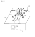
- Fig. 10 shows a sketch of a situation that the ship shaped collector head and a plurality of springs 102 of a pantograph cannot be directly photographed.
- a ship-shaped body 101 and a spring portion 102 of a pantograph 100 are protected by a cover 103.
- an upper end of the ship-shaped body 101 and an upper end of the cover 103 are connected each other. If any force is applied on the upper end of the cover 103, the ship-shaped body 101 is linked with the cover 103 so that the ship-shaped body 101 and the cover 103 are displaced.
- a collector head support member 104 is not directly connected to the cover 103.
- the support member is not smoothly moved relative to the displacement of the cover 103. Therefore, even if a maker is simply adhered on a position of a surface of the cover 103 beyond a position where the spring member 102 is located, the maker is also displaced with the cover 13. An elasticity of the spring member 102 cannot be measured.
- right side and left side springs 102 are virtually combined so that a combined spring 1 is deemed to be located at the center of ship-shaped body 101 along a width direction.
- an upper central maker 2C is mounted on an upper central portion of a cover 103 (corresponding to the ship-shaped body 101).
- a left side upper marker 2L and a right side upper marker 2R is mounted, respectively.
- a lower maker is mounted on a lower central portion of the cover 103 corresponding to the ship-shaped support member 104.
- a relative displacement between the upper central portion of the cover 103 (corresponding to the ship-shaped body 1) and the central portion of the ship-shaped body support member 104 is calculated in order to compute an elasticity of a virtual combined spring 1.
- the relative displacement indicates a positional gap between a position of the upper central marker 2C and the lower marker 3.
- an elasticity of the virtual combined spring 1 can be detected.
- a spring reaction force can be detected by multiplying a combined spring constant with the detected elasticity of the virtual combined spring 1.
- pantograph 100 in which the ship-shaped body 101 is supported by two left- and right- springs 102
- a pantograph in which a ship-shaped body 101 is supported by springs 102 which are more than two springs is also applicable to compute an elasticity of a virtual combined spring 1.
- the contact force measurement method and the contact force measurement device according to the present embodiment are also applicable to a conventional pantograph in which a ship-shaped body 101 and a spring portion 102 are directly photographed.
- Fig. 1 shows a sketch of a construction of the contact force measurement device according to the first embodiment of the present invention.
- line sensors 11L, 11C and 11R are mounted on a train body 10 and a lighting device 12 is provided at a position near the sensors.
- a non light-reflective black material is provided at a cover portion 103 of the pantograph 100 and a light-reflective white material is provided as upper markers 2L, 2C and 2R and a lower marker 3. Light is irradiated toward the upper markers 2L, 2C and 2R and the lower maker 3.
- Images of the upper central marker 2C and the lower marker 3 are recorded by the central line sensor 11C. Images of the upper left side marker 2L is recorded by the left side line sensor 11L. Imaged of the upper right side marker 2R is recorded by the right side line sensor 11R. Images recorded by the line sensors 11L, 11C and 11R are stored in a computer 13 set inside the train body 10.
- a position of the upper central marker 2C and a position of the lower marker 3 at the central portion of the pantograph 100 are detected by processing the images recorded by the central line sensor 11c. Then, the relative displacement is computed in accordance with the position of the upper central portion 2C and the position of the lower marker 3.
- an elasticity of the virtual combined spring 1 is calculated.
- a spring reaction force is detected by multiplying the elasticity of the virtual combined spring 1 with the combined virtual spring constant.
- the images recorded by the line sensors 11L, 11C and 11R are processed by the computer 13 so that the positions of the upper markers 2L, 2C and 2R of the pantograph 100 are detected.
- the displacement of the upper markers 2L, 2C and 2R are differentiated twice so that an acceleration of the pantograph 10 can be obtained.
- An inertial force of the pantograph 100 is detected by multiplying the obtained acceleration and the equivalent mass of the pantograph 100.
- lifting force applied on the ship-shaped body 101 is influenced to the result of the contact force measurement.
- the lifting force is detected by the following equation (1).
- F earo 1 ⁇ 2 ⁇ C L ⁇ ⁇ V 2 ⁇ S
- C L is a lift force coefficient of a ship-shaped body
- p air density
- V running velocity
- S is a surface area.
- the running velocity V is calculated in accordance with the image data and an actual synthesized running data of the actual train body 10.
- the other parameters can be experimentally detected.
- FIG. 2 is a flow chart for showing steps of a contact force measurement method according to the first embodiment of the present invention.
- a step P10 images recorded by the line sensors 11L, 11C and 11C are stored in the computer 13 set inside the train body 10.
- the positions of the upper markers 2L, 2C and 2R and the lower marker 3 are detected by comparing a pattern matching previously obtained in the computer in which a template of the upper markers 2L, 2C and 2R and the lower marker 3 is memorized.
- a step P12 the relative displacement of the central portion of the pantograph 100 is computed by the computer 13.
- the elasticity of the virtual combined spring 1 is computed.
- a spring reaction force is detected by multiplying the elasticity with a spring constant of the virtual combined spring 1.
- the secondary order differentiate is operated with respect to the displacement of the upper markers 2L, 2C and 2R by the computer 13 so as to obtain an acceleration of the pantograph 100.
- the inert force is detected by multiplying the acceleration with the surface area of the pantograph 100.
- a lifting force is detected in accordance with the images and the synthesized actual running velocity of the train body 10 in the computer 13.
- a contact force of the pantograph 100 is obtained by adding the spring reaction detected in the step P12, the inert force detected in the step P13 and the lifting force detected in the step 14 in the computer 13.
- a contact force can be detected by processing the images recorded by the line sensors 11L, 11C and 11R without contacting the pantograph 100.
- it is unnecessary to operate some specific steps such as a step for arranging cable wires and holes so as to set sensors and LED devices on the pantograph 100 in the present embodiment.
- a contact force of the pantograph can be accurately measured with a high space analysis capability and a high synthesized capability by utilizing the line sensors 11L, 11C and 11R.
- FIG. 5 shows a sketch of a construction of a contact force measurement device according to the second embodiment of the present invention.
- the contact force measurement device according to the second embodiment is almost similar to that according to the first embodiment except a matter as described as follows.
- a left upper marker 2L of the both left and right markers 2L and 2R is virtually arranged at a position linearly predicted based on a position of the right upper marker 2R and a position of the center upper marker 2C so that a contact force of a pantograph 100 can be detected without providing a left line sensor 11L.
- one of the left and right line sensors 11L and 11R out of three line sensors 11L, 11C and 11R as shown in Fig. 1 may be omitted.
- the left line sensor 11L is omitted.
- a point extended from the central upper marker 2C with a distance L is recognized as a virtual marker point 4 on which another maker is deemed virtually located.
- Fig. 6 is a flow chart for showing the steps of the contact force measurement method according to the second embodiment of the present invention.
- images recorded by the line sensors 11C and 11R are stored in a computer 13 set inside the train body 10.
- a step P21 the positions of the upper markers 2C and 2R and the lower marker 3 are detected by comparing a pattern matching previously obtained in the computer 13 in which a template of the upper markers 2C and 2R and the lower marker 3 is memorized.
- a virtual marker point 4 is detected by a linear prediction. This step is different from the steps in the contact force measurement method according to the first embodiment.
- a step 23 the relative displacement of the central portion of the pantograph 100 is computed by the computer 13.
- the elasticity of the virtual combined spring 1 is computed.
- a spring reaction force is detected by multiplying the elasticity with a spring constant of the virtual combined spring 1.
- the secondary order differentiate is operated with respect to the displacement of the upper markers 2C and 2R by the computer 13 so as to calculate an acceleration of the pantograph 100.
- the inert force is detected by multiplying the acceleration with the surface area of the pantograph 100.
- a lifting force is detected in accordance with the images and the synthesized actual running velocity of the train body 10 in the computer 13.
- a contact force of the pantograph 100 is obtained by adding the spring reaction detected in the step P23, the inert force detected in the step P24 and the lifting force detected in the step 25 in the computer 13.
- a contact force of the pantograph 100 can be detected by recognizing the virtual marker point 4 in accordance with the positions of the right upper marker 2R and the central upper marker 2C.
- the left line sensor 11L provided at the contact force measurement device according to the first embodiment can be omitted.
- the left upper marker 2L provided at the contact force measurement device according to the first embodiment can be omitted so that the patter matching for detecting a position of the left upper marker 2L in the recorded image is unnecessary. Thus, a number of the pattern matching can be reduced.
- the steps can be processed more quickly in the second embodiment.
- Fig. 9 is a sketch for showing an example how a ship-shaped body is bent by elastic vibration in a contact force measurement device according to the third embodiment.
- a shown in Fig. 9 in a vibration frequency range within that an influence of elastic vibration of a ship-shaped body 101 cannot be ignored, the ship-shaped body 101 is bent so that a displacement of the ship-shaped body 101 cannot be measured correctly in a view point from a central upper marker 2C of a cover 103.
- a relative displacement is calculated by the average point 5 of the lift upper marker 2L and the right upper marker 2R and the position of the lower marker 3.
- the central upper marker 2C is provided in the present embodiment, the central upper marker 2C may be omitted.
- Fig. 8 shows a sketch of an example of a relative displacement by a contact force measurement device according to the third embodiment of the present invention.
- a relative displacement is recognized as a distance between an upper position of a combined spring 1 detected by the average point 5 of the left upper marker 2L and the right upper marker 2R and the lower position of the combined spring 1 detected by the lower marker 3.
- the relative displacement is a gap between the average point 5 of the left upper marker 2L and the right upper marker 2R and the lower marker 3 as shown an arrow D in Fig. 8 and Fig. 9 .
- the positions of the upper left and right markers 2L and 2R and the lower marker 3 are detected in the stored images of the pantograph by comparing a pattern matching previously obtained in the computer 13 in which a template of the upper markers 2L and 2R and the lower marker 3 is memorized.
- a step P12 the relative displacement of the central portion of the pantograph 100 is computed based on the average point 5 of left upper marker 2L and the right upper marker 5 and a position of the lower marker 3 by the computer 13.
- the elasticity of the virtual combined spring 1 is computed.
- a spring reaction force is detected by multiplying the elasticity with a spring constant of the virtual combined spring 1.
- the secondary order differentiate is operated with respect to the displacement of the upper markers 2L and 2R and a displacement of the average point 5 of the left upper marker 2L and the right upper marker 2R by the computer 13 so as to calculate an acceleration of the pantograph 100.
- the inert force is detected by multiplying the calculated acceleration and the equivalence mass of the pantograph 100.
- the central upper marker 2C may be omitted. Further, in the case of one vibration frequency range wherein an elastic vibration of the ship-shaped body 101 can be ignored, that is, in the case that the ship-shaped body 101 is not bent, the contact force measurement method according to the first embodiment may be operated. In the case of another vibration frequency range wherein an elastic vibration of the ship-shaped body 101 cannot be ignored, that is, in the case that the ship-shaped body 101 is bent, the contact force measurement method according to the present embodiment may be operated.
- the present invention is applicable to a contact force measurement method for measuring a contact force of a pantograph by processing picture image and its contact force measurement device, particularly to a contact force measurement method for measuring a contact force of a pantograph of which a ship-shaped body and a spring cannot be directly photographed without utilizing a spring elasticity.
Landscapes
- Physics & Mathematics (AREA)
- General Physics & Mathematics (AREA)
- Engineering & Computer Science (AREA)
- Manufacturing & Machinery (AREA)
- Mechanical Engineering (AREA)
- Force Measurement Appropriate To Specific Purposes (AREA)
- Current-Collector Devices For Electrically Propelled Vehicles (AREA)
Abstract
Description
- The present invention relates to a contact force measurement method and a contact force measurement device.
- In an electric train system, an electric collector device mounted on a roof of a train such as a pantograph and an overhead wire contact with each other so that electric power is supplied. A contact force is produced between the pantograph and the overhead wire. In the case that the contact force is varied so much, the pantograph would be released from the overhead wire. A discharge phenomenon called as "ark" is happened between the released pantograph and the overhead wire. If such an ark is happened, the overhead wire is worn away. On the contrary, in the case that the contact force is too large, the overhead wire is also worn away. Thus, it is preferable that the contact force is not varied so much.
- In order to treat with a method for preventing an overhead wire from being released and an abrasion diagnose with respect to the overhead wire, it is expected to measure a value of a contact force.
Patent document 1 as described below discloses that a frequency response function of a pantograph depending on a variation of contact force is previously measured and the contact force is calculated by convolution integrate with time series response of a moving pantograph and the frequency response function. - Patent document 2 as described below discloses a method for measuring contact force wherein sensors such as an acceleration meter, a strain gauge and so on are arranged at a pantograph. The contact force of the pantograph is obtained by measuring a spring reaction force and an inert force of the pantograph.
Patent document 3 as described below discloses a method for measuring contact force of a pantograph wherein two pairs of upper and lower lighting sources such as LED are provided at a spring portion of the pantograph. The contact force of the pantograph is obtained by processing images of the light sources captured by a CCD camera and a relative displacement of the spring portion is detected. Thus, by detecting an elasticity of the spring, the contact force of the pantograph can be obtained. -
Patent document 4 discloses a method for measuring a contact force of the pantograph wherein line sensor cameras (hereinafter, it is referred as "line sensors") are provided at a position above a roof portion of the pantograph and imaged of a spring portion of the pantograph is captured. By detecting a relative displacement by processing captured images, the elasticity of the spring is detected. Thus, the contact force of the pantograph is obtained. However, thepatent document 4 does not disclose how captured images are processed in detail. -
Patent document 5 discloses a method for measuring a displacement of a pantograph wherein a striped marker of which some parts are high light reflective regions and the remained parts are low reflective regions is mounted at the pantograph and line sensors are arranged at a roof portion of a train body in order to photographs images of the marker along a vertical direction. By detecting a position of the marker with a pattern matching, the displacement of the pantograph is detected. - In the
patent document 5, time series images recorded per every time unit by scanning along a vertical direction are approximately compared with a marker pattern corresponding to striped design in order to judge whether the images are coincident with the marker pattern or similar to the marker patter. Thus, even if the images are recorded under sun shine, the pattern-like images can be distinguished from the others. Even if brightness is dynamically changed at a photographing moment, for example, in the case that a train runs into/out a tunnel, the time series images can be obtained. In accordance with the method disclosed in thepatent document 5 as described below, a relative displacement of a pantograph and a spring elasticity can be detected. -
- Patent document 1: Japanese Patent Unexamined Publication No.
11-194059 - Patent document 2: Japanese Patent Unexamined Publication No.
2004-301591 - Patent document 3: Japanese Patent Unexamined Publication No.
2001-235310 - Patent document 4: Japanese Patent Unexamined Publication No.
2008-185457 - Patent document 5: Japanese Patent Unexamined Publication No.
2008-104312 - However, for example, in the case of arranging sensors on a pantograph in the method disclosed in the patent document 2, some special processes are necessary for providing wire harness and holes through which a wire is passed. Further, in the case of arranging the LED disclosed in the patent document, it is necessary for a pantograph to process some steps for mounting the LED and a battery source for the LED.
- In the contact force measurement method disclosed in the
patent document 4, a contact force is measured by processing recorded images without contacting with a pantograph. It is unnecessary to process the pantograph. Thus, its method can be broadly applicable. However, in this method, it is necessary to detect displacements of an upper portion and a lower portion of springs so as to calculate elasticity of the springs, it is necessary to record markers attached to the upper and lower portions of the springs by line sensor cameras. - In the method disclosed in the
patent documents patent documents - Upon considering the above drawbacks, the present invention provides a contact force measurement method for measuring a contact force of a pantograph by processing images in the case of the pantograph of which a ship shaped body and a spring cannot be directly recorded and its contact force measurement device.
- To resolve the above drawbacks, a contact force measurement method according to the first invention is a method for measuring a contact force of a pantograph wherein a ship-shaped body of a collector head is supported by a ship-shaped body support member through a plurality of springs, wherein the contact force measurement method is characterized of comprising a step for recording images of the pantograph; a step for deeming a virtual combined spring at a central portion of the pantograph along a width direction by combining the plurality of springs, calculating a relative displacement between a position at the central portion of the pantograph along the width direction corresponding to the ship-shaped body and the ship-shaped body support member, and computing elasticity of the virtual combined spring by detecting a difference between the relative displacement and a natural length of the virtual combined spring in order to detect a spring reaction force by multiplying the elasticity with a spring constant of the virtual combined spring; a step for operating second order differentiate with respect to a displacement at the position corresponding to the ship-shaped body in order to calculate acceleration of the pantograph in accordance with the images and calculating an inert force by multiplying the acceleration with an equivalent mass of the pantograph; a step for detecting a lifting force based on the imaged and speed data of actual running train those are time synchronized; and a step for measuring a contact force by adding the lifting force, the inert force and the lifting force.
- To resolve the above drawbacks, a contact force measurement method according to the second invention is characterized of comprising a step for detecting positions of markers, wherein one marker is arranged at the central portion of the pantograph along the width direction corresponding to the ship-shaped body, two other markers are arranged at the both sides of the pantograph, each marker is arranged at one side of the pantograph along the width direction corresponding to the ship-shaped body, and another one marker is arranged at the ship-shaped support; the step for detecting positions of markers characterized of including a step for detecting positioned of three the markers arranged at the pantograph corresponding to the ship-shaped body and a position of the marker arranged at the ship-shaped body support by processing the images in the contact force measurement method according the first invention..
- To resolve the above drawbacks, a contact force measurement method according to the third invention is characterized of comprising a step for detecting positions of markers, wherein two markers are arranged at the both sides of the pantograph along the width direction corresponding to the ship-shaped body, each marker is arranged at one side of the pantograph, and one other marker is arranged at the ship-shaped support; the step for detecting positions of markers characterized of including a step for detecting positions of two the markers arranged at the both sides of the pantograph corresponding to the ship-shaped body and a position of the other marker arranged at the ship-shaped body support by processing the images in the contact force measurement method according the first invention.
- To resolve the above drawbacks, a contact force measurement method according to the fourth invention comprises a step for detecting positions of markers in the contact force measurement method according to the first invention, wherein one marker is arranged at the central portion of the pantograph along the width direction corresponding to the ship-shaped body, another marker is arranged at one of the both sides of the pantograph along the width direction corresponding to the ship-shaped body, and the other marker is arranged at the ship-shaped support, wherein the step for detecting positions of markers is characterized of including a step for detecting positions of two markers arranged at the pantograph corresponding to the ship-shaped body and a position of the marker arranged at the ship-shaped support, wherein a virtual marker is deemed to be positioned at a point linearly predicted in accordance with a position of the marker arranged at the central portion of the pantograph corresponding to the ship-shaped body and the marker arranged at one of the both sides of the pantograph along the width direction corresponding to the ship-shaped body.
- To resolve the above drawbacks, a contact force measurement device according to the fifth invention is a contact force measurement device for measuring a contact force of a pantograph wherein a ship-shaped body of a collector head is supported by a ship-shaped body support member through a plurality of springs, wherein the contact force measurement device is characterized of comprising record means for recording images of the pantograph; and measurement means for measuring a contact force of the pantograph, wherein a virtual combined spring is deemed to be positioned at a central portion of the pantograph along the width direction by combining the plurality of the springs, a relative displacement is calculated in accordance with the central portion of the pantograph along the width direction corresponding to the ship-shaped body and the ship-shaped support by processing the images, a difference between the relative displacement and a natural length of the virtual combined spring so as to calculate elasticity of the virtual combined spring, a spring reaction force is detected by multiplying the elasticity with a spring constant of the virtual combined spring, an acceleration of the pantograph is detected by differentiating a displacement of the ship-shaped body by processing the images, an inert force is detected by multiplying the acceleration with an equivalent mass of the pantograph, a lifting force applied to the pantograph is detected by processing the images and a synchronized data of an actual running supped of a train and the measurement means detect a contact force by adding the spring reaction force, the inert force and the lifting force.
- To resolve the above drawbacks, a contact force measurement device according to the sixth invention is characterized in that one marker is arranged at the central portion of the pantograph along the width direction corresponding to the ship-shaped body, two other markers are arranged at the both sides of the pantograph, each marker is arranged at one side of the pantograph along the width direction corresponding to the ship-shaped body, and another one marker is arranged at the ship-shaped support, the measurement means detect positions of three the markers arranged at the pantograph corresponding to the ship-shaped body and a position of the marker arranged at the ship-shaped body support by processing the images in the contact force measurement device according to the fifth invention..
- To resolve the above drawbacks, a contact force measurement device according to the seventh invention is characterized in that two markers are arranged at the both sides of the pantograph along the width direction corresponding to the ship-shaped body, each marker is arranged at one side of the pantograph, and one other marker is arranged at the ship-shaped support, the measurement means detect positions of two the markers arranged at the both sides of the pantograph corresponding to the ship-shaped body and a position of the other marker arranged at the ship-shaped body support by processing the images in the contact force measurement device according to the fifth invention.
- To resolve the above drawbacks, a contact force measurement device according to the eighth invention is characterized in that one marker is arranged at the central portion of the pantograph along the width direction corresponding to the ship-shaped body, another marker is arranged at one of the both sides of the pantograph along the width direction corresponding to the ship-shaped body, and the other marker is arranged at the ship-shaped support, the measurement means detect positions of two markers arranged at the pantograph corresponding to the ship-shaped body and a position of the marker arranged at the ship-shaped support, wherein a virtual marker is deemed to be positioned at a point linearly predicted in accordance with a position of the marker arranged at the central portion of the pantograph corresponding to the ship-shaped body and the marker arranged at one of the both sides of the pantograph along the width direction corresponding to the ship-shaped body in the contact force measurement device according to the fifth invention.
- According to the present invention, even if a ship-shaped body and springs of a pantograph cannot be directly photographed or recorded, the contact force measurement method and its contact force measurement device can detect a contact force of the pantograph by processing photographed or recorded images.
-
- [
Fig. 1] Fig. 1 shows a sketch of a construction of a contact force measurement device according to the first embodiment of the present invention. - [
Fig. 2] Fig. 2 is a flow chart for showing processes of a contact force measurement method according to the first embodiment of the present invention. - [
Fig. 3] Fig. 3 shows a sketch of a spring virtually combined in the first embodiment. - [
Fig. 4] Fig. 4 shows a sketch for showing where markers according to the first embodiment are located. - [
Fig. 5] Fig. 5 shows a sketch of a construction of a contact force measurement device according to the second embodiment of the present invention. - [
Fig. 6] Fig. 6 is a flow chart for showing process of a contact force measurement method according to the second embodiment of the present invention. - [
Fig. 7] Fig. 7 shows an example of a method for reducing a number of line sensor bases by a linear prediction of positions of makers according to the second embodiment. - [
Fig. 8] Fig. 8 shows a sketch of an example of a relative displacement by a contact force measurement device according to the third embodiment of the present invention. - [
Fig. 9] Fig. 9 is a sketch for showing an example how a ship-shaped body is bent by elastic vibration in a contact force measurement device according to the third embodiment. - [
Fig. 10] Fig. 10 shows a sketch of an example that a ship shaped body and a spring portion of a pantograph can be directly photographed. - The embodiments to practice a contact force measurement method according to the present invention will be described with reference to the accompanying drawings.
- A contact force measurement method and a contact force measurement device according to the first embodiment of the present invention will be described.
In the contact force measurement method and the contact force measurement device according to the first embodiment, even if a collector head having a ship-shaped body and a spring member of a pantograph cannot be directly photographed, the resent embodiment is characterized in that a contact force of the pantograph can be measured by a non-contact measurement method with an observation of a relative displacement at a central portion of the pantograph and acceleration at three points. -
Fig. 10 shows a sketch of a situation that the ship shaped collector head and a plurality ofsprings 102 of a pantograph cannot be directly photographed.
As shown inFig. 10 , a ship-shapedbody 101 and aspring portion 102 of apantograph 100 are protected by acover 103. Under the construction, an upper end of the ship-shapedbody 101 and an upper end of thecover 103 are connected each other. If any force is applied on the upper end of thecover 103, the ship-shapedbody 101 is linked with thecover 103 so that the ship-shapedbody 101 and thecover 103 are displaced. - However, a collector
head support member 104 is not directly connected to thecover 103. The support member is not smoothly moved relative to the displacement of thecover 103. Therefore, even if a maker is simply adhered on a position of a surface of thecover 103 beyond a position where thespring member 102 is located, the maker is also displaced with thecover 13. An elasticity of thespring member 102 cannot be measured. - Therefore, in the contact force measurement method according to the embodiment, as shown in
Fig. 3 , right side and left side springs 102 are virtually combined so that a combinedspring 1 is deemed to be located at the center of ship-shapedbody 101 along a width direction. As shown inFig. 4 , an uppercentral maker 2C is mounted on an upper central portion of a cover 103 (corresponding to the ship-shaped body 101). At the both sides of thecover 103 along the width direction, a left sideupper marker 2L and a right sideupper marker 2R is mounted, respectively. A lower maker is mounted on a lower central portion of thecover 103 corresponding to the ship-shapedsupport member 104. - A relative displacement between the upper central portion of the cover 103 (corresponding to the ship-shaped body 1) and the central portion of the ship-shaped
body support member 104 is calculated in order to compute an elasticity of a virtual combinedspring 1. Herein, as shown an arrow D inFig. 4 , the relative displacement indicates a positional gap between a position of the uppercentral marker 2C and thelower marker 3. - By computing a difference between a displacement of the virtual combined
spring 1 without an elastic force (a natural length) and the detected relative displacement, an elasticity of the virtual combinedspring 1 can be detected. A spring reaction force can be detected by multiplying a combined spring constant with the detected elasticity of the virtual combinedspring 1. - In the present embodiment, although the
pantograph 100 in which the ship-shapedbody 101 is supported by two left- and right-springs 102, a pantograph in which a ship-shapedbody 101 is supported bysprings 102 which are more than two springs is also applicable to compute an elasticity of a virtual combinedspring 1. - In the present embodiment, although the ship-shaped
body 101 and thespring portion 102 cannot be directly photographed, the contact force measurement method and the contact force measurement device according to the present embodiment are also applicable to a conventional pantograph in which a ship-shapedbody 101 and aspring portion 102 are directly photographed. -
Fig. 1 shows a sketch of a construction of the contact force measurement device according to the first embodiment of the present invention. In the contact force measurement device according to the present embodiment as shown inFig. 1 ,line sensors train body 10 and alighting device 12 is provided at a position near the sensors. - As shown in
Fig. 1 andFig. 4 , a non light-reflective black material is provided at acover portion 103 of thepantograph 100 and a light-reflective white material is provided asupper markers lower marker 3. Light is irradiated toward theupper markers lower maker 3. - Images of the upper
central marker 2C and thelower marker 3 are recorded by thecentral line sensor 11C. Images of the upperleft side marker 2L is recorded by the leftside line sensor 11L. Imaged of the upperright side marker 2R is recorded by the rightside line sensor 11R. Images recorded by theline sensors computer 13 set inside thetrain body 10. - A position of the upper
central marker 2C and a position of thelower marker 3 at the central portion of thepantograph 100 are detected by processing the images recorded by the central line sensor 11c. Then, the relative displacement is computed in accordance with the position of the uppercentral portion 2C and the position of thelower marker 3. By detecting a difference between the relative displacement and the natural length of the virtual combinedspring 1, an elasticity of the virtual combinedspring 1 is calculated. A spring reaction force is detected by multiplying the elasticity of the virtual combinedspring 1 with the combined virtual spring constant. - The images recorded by the
line sensors computer 13 so that the positions of theupper markers pantograph 100 are detected. The displacement of theupper markers pantograph 10 can be obtained. An inertial force of thepantograph 100 is detected by multiplying the obtained acceleration and the equivalent mass of thepantograph 100. - Further, in an actual case, lifting force applied on the ship-shaped
body 101 is influenced to the result of the contact force measurement. Thus, the lifting force is detected by the following equation (1).
In the above equation (1), CL is a lift force coefficient of a ship-shaped body, p is air density, V is running velocity and S is a surface area. The running velocity V is calculated in accordance with the image data and an actual synthesized running data of theactual train body 10. The other parameters can be experimentally detected. Finally, by adding the spring reaction force, the inert force and the lifting force detected by the above method, a contact force of thepantograph 100 can be detected. - In the next, it will be described steps in the contact force measurement method according to the present embodiment.
Fig. 2 is a flow chart for showing steps of a contact force measurement method according to the first embodiment of the present invention. - As shown in
Fig. 2 , at first, in a step P10, images recorded by theline sensors computer 13 set inside thetrain body 10.
In the next, in a step P11, the positions of theupper markers lower marker 3 are detected by comparing a pattern matching previously obtained in the computer in which a template of theupper markers lower marker 3 is memorized. - In a step P12, the relative displacement of the central portion of the
pantograph 100 is computed by thecomputer 13. By detecting a difference between the relative displacement and a natural length of the virtual combinedspring 1, the elasticity of the virtual combinedspring 1 is computed. Thus, a spring reaction force is detected by multiplying the elasticity with a spring constant of the virtual combinedspring 1. - In a step P13, the secondary order differentiate is operated with respect to the displacement of the
upper markers computer 13 so as to obtain an acceleration of thepantograph 100. The inert force is detected by multiplying the acceleration with the surface area of thepantograph 100. - In a step P14, a lifting force is detected in accordance with the images and the synthesized actual running velocity of the
train body 10 in thecomputer 13.
Finally, in a step P15, a contact force of thepantograph 100 is obtained by adding the spring reaction detected in the step P12, the inert force detected in the step P13 and the lifting force detected in the step 14 in thecomputer 13.
These steps described above are the contact force measurement method according to the present embodiment. - As described above, in the contact force measurement method and the contact force measurement device according to the present embodiment, even if a ship-shaped
body 101 and aspring portion 102 arranged at apantograph 100 cannot be directly photographed, a contact force of the pantograph can be measured accurately. - According to the contact force measurement method and the contact force measurement device of the present embodiment, a contact force can be detected by processing the images recorded by the
line sensors pantograph 100. Upon comparing the method of the present embodiment and the method disclosed in thePatent Documents 2 and 3, it is unnecessary to operate some specific steps such as a step for arranging cable wires and holes so as to set sensors and LED devices on thepantograph 100 in the present embodiment. - According to the contact force measurement method and the contact force measurement device according to the present embodiment, a contact force of the pantograph can be accurately measured with a high space analysis capability and a high synthesized capability by utilizing the
line sensors - A contact force measurement method and the contact force measurement device of the second embodiment according to the present invention will be described hereinafter.
Fig. 5 shows a sketch of a construction of a contact force measurement device according to the second embodiment of the present invention.
As shown inFig. 5 , the contact force measurement device according to the second embodiment is almost similar to that according to the first embodiment except a matter as described as follows. In the second embodiment, a leftupper marker 2L of the both left andright markers upper marker 2R and a position of the centerupper marker 2C so that a contact force of apantograph 100 can be detected without providing aleft line sensor 11L. - That is, in the contact force measurement device according to the second embodiment, one of the left and
right line sensors line sensors Fig. 1 may be omitted. In the present embodiment, it will be described the case in which theleft line sensor 11L is omitted. - In the present embodiment as shown in
Fig. 7 , on a line S aligning from the rightupper marker 2R to the centralupper marker 2C, a point extended from the centralupper marker 2C with a distance L is recognized as avirtual marker point 4 on which another maker is deemed virtually located. Thereby, even if theleft line sensor 11L is omitted, the displacement of thepantograph 100 at the three points can be detected by utilizing thevirtual marker point 4. - The steps of the contact force measurement method according to the present embodiment will be described.
Fig. 6 is a flow chart for showing the steps of the contact force measurement method according to the second embodiment of the present invention.
As shown inFig. 6 , at the first, in a step P20, images recorded by theline sensors computer 13 set inside thetrain body 10. - In a step P21, the positions of the
upper markers lower marker 3 are detected by comparing a pattern matching previously obtained in thecomputer 13 in which a template of theupper markers lower marker 3 is memorized. - In a step P22, after the pattern matching by the
computer 13, avirtual marker point 4 is detected by a linear prediction. This step is different from the steps in the contact force measurement method according to the first embodiment. - In a step 23, the relative displacement of the central portion of the
pantograph 100 is computed by thecomputer 13. By detecting a difference between the relative displacement and a natural length of the virtual combinedspring 1, the elasticity of the virtual combinedspring 1 is computed. Thus, a spring reaction force is detected by multiplying the elasticity with a spring constant of the virtual combinedspring 1. - In a step P24, the secondary order differentiate is operated with respect to the displacement of the
upper markers computer 13 so as to calculate an acceleration of thepantograph 100. The inert force is detected by multiplying the acceleration with the surface area of thepantograph 100. - In a step P125, a lifting force is detected in accordance with the images and the synthesized actual running velocity of the
train body 10 in thecomputer 13.
Finally, in a step P26, a contact force of thepantograph 100 is obtained by adding the spring reaction detected in the step P23, the inert force detected in the step P24 and the lifting force detected in the step 25 in thecomputer 13.
The steps described above are the contact force measurement method according to the second embodiment. - As described above, in the contact force measurement method and the contact force measurement device according to the second embodiment, in addition to the effects obtained by the contact force measurement method and the contact force measurement device according to the first embodiment, a contact force of the
pantograph 100 can be detected by recognizing thevirtual marker point 4 in accordance with the positions of the rightupper marker 2R and the centralupper marker 2C. Thus, theleft line sensor 11L provided at the contact force measurement device according to the first embodiment can be omitted. - In according to the contact force measurement method and the contact force measurement device according to the second embodiment, the left
upper marker 2L provided at the contact force measurement device according to the first embodiment can be omitted so that the patter matching for detecting a position of the leftupper marker 2L in the recorded image is unnecessary. Thus, a number of the pattern matching can be reduced. Upon comparing the second embodiment and the first embodiment, the steps can be processed more quickly in the second embodiment. - A contact force measurement method and a contact force measurement device of the third embodiment according to the present invention will be described.
Fig. 9 is a sketch for showing an example how a ship-shaped body is bent by elastic vibration in a contact force measurement device according to the third embodiment.
A shown inFig. 9 , in a vibration frequency range within that an influence of elastic vibration of a ship-shapedbody 101 cannot be ignored, the ship-shapedbody 101 is bent so that a displacement of the ship-shapedbody 101 cannot be measured correctly in a view point from a centralupper marker 2C of acover 103. Thus, it is necessary to recognize anaverage point 5 of a leftupper marker 2L and a rightupper marker 2R as a point described above a combinedspring 1. - Although a structure of the contact force measurement device according to the third embodiment is as similar as that according to the first embodiment, in the third embodiment, a relative displacement is calculated by the
average point 5 of the liftupper marker 2L and the rightupper marker 2R and the position of thelower marker 3. Although the centralupper marker 2C is provided in the present embodiment, the centralupper marker 2C may be omitted. -
Fig. 8 shows a sketch of an example of a relative displacement by a contact force measurement device according to the third embodiment of the present invention.
In the present embodiment as shown inFig. 8 , a relative displacement is recognized as a distance between an upper position of a combinedspring 1 detected by theaverage point 5 of the leftupper marker 2L and the rightupper marker 2R and the lower position of the combinedspring 1 detected by thelower marker 3. Herein, the relative displacement is a gap between theaverage point 5 of the leftupper marker 2L and the rightupper marker 2R and thelower marker 3 as shown an arrow D inFig. 8 andFig. 9 . - In the next, it will be described process steps in the contact force measurement method according to the present embodiment.
The process of the contact force measurement method according to the present embodiment is almost equal to the process of the contact force measurement method according to the first embodiment except the steps P11 to P13 as described as follows. - In the third embodiment, in a step P11 as shown in
Fig. 2 , the positions of the upper left andright markers lower marker 3 are detected in the stored images of the pantograph by comparing a pattern matching previously obtained in thecomputer 13 in which a template of theupper markers lower marker 3 is memorized. - In a step P12, the relative displacement of the central portion of the
pantograph 100 is computed based on theaverage point 5 of leftupper marker 2L and the rightupper marker 5 and a position of thelower marker 3 by thecomputer 13. By detecting a difference between the relative displacement and a natural length of the virtual combinedspring 1, the elasticity of the virtual combinedspring 1 is computed. Thus, a spring reaction force is detected by multiplying the elasticity with a spring constant of the virtual combinedspring 1. - In a step P13, the secondary order differentiate is operated with respect to the displacement of the
upper markers average point 5 of the leftupper marker 2L and the rightupper marker 2R by thecomputer 13 so as to calculate an acceleration of thepantograph 100. The inert force is detected by multiplying the calculated acceleration and the equivalence mass of thepantograph 100. - In the embodiment as described above, although the central
upper marker 2C is provided, the centralupper marker 2C may be omitted. Further, in the case of one vibration frequency range wherein an elastic vibration of the ship-shapedbody 101 can be ignored, that is, in the case that the ship-shapedbody 101 is not bent, the contact force measurement method according to the first embodiment may be operated. In the case of another vibration frequency range wherein an elastic vibration of the ship-shapedbody 101 cannot be ignored, that is, in the case that the ship-shapedbody 101 is bent, the contact force measurement method according to the present embodiment may be operated. - As described above, in accordance with the contact force measurement method and the contact force measurement device according to the present embodiment, even if the ship-shaped
body 101 and thespring 102 of apantograph 100 cannot be directly photographed and the ship-shapedbody 101 is bend in the vibration frequency range wherein the elastic vibration of the ship-shapedbody 101 cannot be ignored, a contact force of thepantograph 100 can be accurately measured. - The present invention is applicable to a contact force measurement method for measuring a contact force of a pantograph by processing picture image and its contact force measurement device, particularly to a contact force measurement method for measuring a contact force of a pantograph of which a ship-shaped body and a spring cannot be directly photographed without utilizing a spring elasticity.
-
- 1
- combined spring
- 2L
- left upper marker
- 2C
- center upper marker
- 2R
- right upper marker
- 3
- lower marker
- 4
- virtual marker point
- 5
- average point
- 10
- train body
- 11L
- left line sensor
- 11C
- central line sensor
- 11R
- right line sensor
- 12
- lighting device
- 13
- computer
- 100
- pantograph
- 101
- ship-shaped body of collector head
- 102
- spring
- 103
- cover
- 104
- collector head support member
Claims (8)
- A contact force measurement method for measuring a contact force of a pantograph wherein a ship-shaped body of a collector head is supported by a ship-shaped body support member through a plurality of springs, the contact force measurement method characterized of comprising:a step for recording images of said pantograph;a step for deeming a virtual combined spring at a central portion of said pantograph along a width direction by combining said plurality of springs, calculating a relative displacement between a position corresponding to said ship-shaped body at said central portion of said pantograph along said width direction and said ship-shaped body support member, and computing elasticity of said virtual combined spring by detecting a difference between said relative displacement and a natural length of said virtual combined spring in order to detect a spring reaction force by multiplying said elasticity with a spring constant of said virtual combined spring;a step for operating second order differentiate with respect to a displacement at said position corresponding to said ship-shaped body in order to calculate acceleration of said pantograph in accordance with said images and calculating an inert force by multiplying said acceleration with an equivalent mass of said pantograph;a step for detecting a lifting force based on said imaged and speed data of actual running train those are time synchronized; anda step for measuring a contact force by adding said lifting force, said inert force and said lifting force.
- A contact force measurement method as claimed in claim 1 characterized of comprising:a step for detecting positions of markers, wherein one marker is arranged at said central portion of said pantograph along the width direction corresponding to said ship-shaped body, two other markers are arranged at the both sides of said pantograph, each marker is arranged at one side of the pantograph along the width direction corresponding to said ship-shaped body, and another one marker is arranged at said ship-shaped support,said step for detecting positions of markers characterized of including a step for detecting positioned of three said markers arranged at the pantograph corresponding to said ship-shaped body and a position of said marker arranged at said ship-shaped body support by processing said images.
- A contact force measurement method as claimed in claim 1 characterized of comprising:a step for detecting positions of markers, wherein two markers are arranged at the both sides of said pantograph along the width direction corresponding to the ship-shaped body, each marker is arranged at one side of the pantograph, and one other marker is arranged at said ship-shaped support,said step for detecting positions of markers characterized of including a step for detecting positions of two said markers arranged at the both sides of said pantograph corresponding to said ship-shaped body and a position of said other marker arranged at said ship-shaped body support by processing said images.
- A contact force measurement method as claimed in claim 1 characterized of comprising:a step for detecting positions of markers, wherein one marker is arranged at said central portion of said pantograph along the width direction corresponding to said ship-shaped body, another marker is arranged at one of the both sides of said pantograph along the width direction corresponding to said ship-shaped body, and the other marker is arranged at said ship-shaped support,said step for detecting positions of markers characterized of including a step for detecting positions of two markers arranged at said pantograph corresponding to said ship-shaped body and a position of said marker arranged at said ship-shaped support, wherein a virtual marker is deemed to be positioned at a point linearly predicted in accordance with a position of said marker arranged at said central portion of said pantograph corresponding to said ship-shaped body and said marker arranged at one of said both sides of said pantograph along the width direction corresponding to said ship-shaped body.
- A contact force measurement device for measuring a contact force of a pantograph wherein a ship-shaped body of a collector head is supported by a ship-shaped body support member through a plurality of springs, the contact force measurement device characterized of comprising:record means for recording images of said pantograph andmeasurement means for measuring a contact force of said pantograph, wherein a virtual combined spring is deemed to be positioned at a central portion of said pantograph along the width direction by combining the plurality of said springs, a relative displacement is calculated in accordance with said central portion of said pantograph along the width direction corresponding to said ship-shaped body and said ship-shaped support by processing said images, a difference between said relative displacement and a natural length of said virtual combined spring so as to calculate elasticity of said virtual combined spring, a spring reaction force is detected by multiplying said elasticity with a spring constant of said virtual combined spring, an acceleration of the pantograph is detected by differentiating a displacement of said ship-shaped body by processing said images, an inert force is detected by multiplying said acceleration with an equivalent mass of said pantograph, a lifting force applied to said pantograph is detected by processing said images and a synchronized data of an actual running supped of a train and said measurement means detect a contact force by adding said spring reaction force, said inert force and said lifting force.
- A contact force measurement device as claimed in claim 5 characterized in that one marker is arranged at said central portion of said pantograph along the width direction corresponding to said ship-shaped body, two other markers are arranged at the both sides of said pantograph, each marker is arranged at one side of the pantograph along the width direction corresponding to said ship-shaped body, and another one marker is arranged at said ship-shaped support,
said measurement means detect positions of three said markers arranged at said pantograph corresponding to said ship-shaped body and a position of said marker arranged at said ship-shaped body support by processing said images. - A contact force measurement device as claimed in claim 5 characterized in that two markers are arranged at the both sides of said pantograph along the width direction corresponding to the ship-shaped body, each marker is arranged at one side of the pantograph, and one other marker is arranged at said ship-shaped support,
said measurement means detect positions of two said markers arranged at the both sides of said pantograph corresponding to said ship-shaped body and a position of said other marker arranged at said ship-shaped body support by processing said images. - A contact force measurement device as claimed in claim 5 characterized in that one marker is arranged at said central portion of said pantograph along the width direction corresponding to said ship-shaped body, another marker is arranged at one of the both sides of said pantograph along the width direction corresponding to said ship-shaped body, and the other marker is arranged at said ship-shaped support,
said measurement means detect positions of two markers arranged at said pantograph corresponding to said ship-shaped body and a position of said marker arranged at said ship-shaped support, wherein a virtual marker is deemed to be positioned at a point linearly predicted in accordance with a position of said marker arranged at said central portion of said pantograph corresponding to said ship-shaped body and said marker arranged at one of said both sides of said pantograph along the width direction corresponding to said ship-shaped body.
Applications Claiming Priority (2)
| Application Number | Priority Date | Filing Date | Title |
|---|---|---|---|
| JP2010104867A JP5443257B2 (en) | 2010-04-30 | 2010-04-30 | Contact force measuring method and contact force measuring device |
| PCT/JP2011/059140 WO2011136021A1 (en) | 2010-04-30 | 2011-04-13 | Contact force measurement method and contact force measurement device |
Publications (3)
| Publication Number | Publication Date |
|---|---|
| EP2565612A1 true EP2565612A1 (en) | 2013-03-06 |
| EP2565612A4 EP2565612A4 (en) | 2015-12-09 |
| EP2565612B1 EP2565612B1 (en) | 2017-01-11 |
Family
ID=44861332
Family Applications (1)
| Application Number | Title | Priority Date | Filing Date |
|---|---|---|---|
| EP11774805.3A Active EP2565612B1 (en) | 2010-04-30 | 2011-04-13 | Contact force measurement method and contact force measurement device |
Country Status (7)
| Country | Link |
|---|---|
| EP (1) | EP2565612B1 (en) |
| JP (1) | JP5443257B2 (en) |
| KR (1) | KR101369581B1 (en) |
| CN (1) | CN102869968B (en) |
| RU (1) | RU2519589C1 (en) |
| TW (1) | TWI434778B (en) |
| WO (1) | WO2011136021A1 (en) |
Cited By (3)
| Publication number | Priority date | Publication date | Assignee | Title |
|---|---|---|---|---|
| EP3725580A1 (en) * | 2019-04-19 | 2020-10-21 | Sncf Reseau | Pantograph provided with a detection system |
| CN112519584A (en) * | 2020-12-09 | 2021-03-19 | 中铁建电气化局集团南方工程有限公司 | Pantograph with self preservation protects device |
| CN113256723A (en) * | 2021-06-29 | 2021-08-13 | 西南交通大学 | Automatic detection method for pantograph lifting time and pantograph head displacement curve |
Families Citing this family (22)
| Publication number | Priority date | Publication date | Assignee | Title |
|---|---|---|---|---|
| US9714965B2 (en) * | 2015-01-20 | 2017-07-25 | Aclara Meters, LLC | System for measuring contact force in a utility meter |
| ITUA20162698A1 (en) * | 2016-04-19 | 2017-10-19 | Mer Mec S P A | OPTICAL SYSTEM FOR THE MEASUREMENT OF THE CONTACT FORCE BETWEEN THE PANTOGRAPH AND THE CATENARY |
| JP6557839B2 (en) * | 2016-05-11 | 2019-08-14 | 公益財団法人鉄道総合技術研究所 | Pantograph lift estimation method and apparatus, and pantograph lift compensation method and apparatus |
| CN107487187B (en) * | 2017-08-25 | 2023-06-30 | 诺和君目(北京)科技有限公司 | Contact pressure feedback pantograph control system |
| CN107560770B (en) * | 2017-08-28 | 2019-06-25 | 南京拓控信息科技股份有限公司 | A kind of detection device of pantograph to contact net stress |
| DE102017218056A1 (en) * | 2017-10-10 | 2019-04-11 | Knorr-Bremse Gmbh | Active control of a pantograph |
| CN108253893B (en) * | 2018-01-23 | 2018-10-12 | 哈尔滨工业大学 | A kind of micro- contact force displacement measuring device of large range high precision and its control method |
| JP7008001B2 (en) * | 2018-08-31 | 2022-01-25 | 株式会社明電舎 | Non-contact pantograph contact force measuring device |
| CN109443811B (en) * | 2018-11-19 | 2021-03-26 | 中国科学院力学研究所 | A method of non-contact measurement of pantograph mode |
| CN110346076A (en) * | 2019-07-04 | 2019-10-18 | 中铁第四勘察设计院集团有限公司 | A kind of side formula pantagraph current collector experimental rig suitable for maglev vehicle |
| US11548165B2 (en) * | 2019-10-10 | 2023-01-10 | Mitsubishi Electric Research Laboratories, Inc. | Elastomeric tactile sensor |
| US11472040B2 (en) * | 2019-10-10 | 2022-10-18 | Mitsubishi Electric Research Laboratories, Inc. | Tactile sensor |
| CN110806236A (en) * | 2019-11-20 | 2020-02-18 | 北京市地铁运营有限公司地铁运营技术研发中心 | Dynamic detection device for bow net pressure and hard points |
| CN112213008A (en) * | 2020-09-30 | 2021-01-12 | 成都唐源电气股份有限公司 | A non-contact pantograph-catenary contact force measurement method and device |
| CN112229550A (en) * | 2020-09-30 | 2021-01-15 | 成都唐源电气股份有限公司 | A non-contact pantograph-catenary contact force measurement system based on dual stereo targets |
| CN112484886B (en) * | 2020-12-10 | 2025-04-01 | 上海地铁维护保障有限公司 | Contact line branch detection device |
| CN112793426B (en) * | 2021-02-24 | 2022-09-02 | 华东交通大学 | Antifriction and wear-resistant pantograph suitable for bidirectional running |
| CN113588300B (en) * | 2021-08-02 | 2023-12-08 | 中车大连机车车辆有限公司 | Railway vehicle test bed contact net analogue means |
| CN113820054B (en) * | 2021-09-22 | 2022-09-30 | 中国科学院力学研究所 | An all-fiber measurement method and system for train rigid pantograph-catenary contact force |
| CN114414116B (en) * | 2021-12-31 | 2023-08-01 | 成都唐源电气股份有限公司 | Bow net contact force analysis method based on triaxial acceleration |
| TWI863361B (en) * | 2023-06-16 | 2024-11-21 | 國立高雄科技大學 | Micro strain displacement measurement device and measurement method |
| CN118225369B (en) * | 2024-05-27 | 2024-07-30 | 中铁建电气化局集团轨道交通器材有限公司 | Testing device and testing method for impact load of integral hanger |
Family Cites Families (15)
| Publication number | Priority date | Publication date | Assignee | Title |
|---|---|---|---|---|
| AT391207B (en) * | 1988-09-09 | 1990-09-10 | Siemens Ag Oesterreich | DEVICE FOR MEASURING CONTACT PRESSURE ON CURRENT COLLECTORS WITH A PRESSURE SENSOR |
| FR2646381B1 (en) * | 1989-04-28 | 1991-07-26 | Faiveley Sa | DEVICE FOR ADJUSTING THE SUPPORT FORCE OF A PANTOGRAPH ON A CATENARY WIRE AND RELATED METHOD |
| JP3888750B2 (en) * | 1997-10-30 | 2007-03-07 | 東海旅客鉄道株式会社 | Measuring method of contact force of pantograph |
| JP3352009B2 (en) | 1997-12-28 | 2002-12-03 | 財団法人鉄道総合技術研究所 | Contact force measuring device |
| JP3699320B2 (en) * | 2000-02-23 | 2005-09-28 | 財団法人鉄道総合技術研究所 | Pantograph displacement, contact force and trolley line deviation measuring device |
| US20020149571A1 (en) * | 2001-04-13 | 2002-10-17 | Roberts Jerry B. | Method and apparatus for force-based touch input |
| JP3790925B2 (en) * | 2001-05-01 | 2006-06-28 | 東日本旅客鉄道株式会社 | Pantograph contact force measuring device |
| US6679524B2 (en) * | 2001-11-14 | 2004-01-20 | Delphi Technologies, Inc. | Tension sensing assembly |
| JP4012108B2 (en) | 2003-03-31 | 2007-11-21 | 財団法人鉄道総合技術研究所 | Pantograph contact force measuring method and contact force measuring device |
| JP4923942B2 (en) * | 2006-10-20 | 2012-04-25 | 株式会社明電舎 | Pantograph measuring device by image processing |
| JP4954732B2 (en) | 2007-01-30 | 2012-06-20 | 公益財団法人鉄道総合技術研究所 | Pantograph contact force measuring method and contact force measuring device |
| JP5245445B2 (en) * | 2008-02-15 | 2013-07-24 | 株式会社明電舎 | Crossover measuring device |
| JP5097596B2 (en) * | 2008-03-31 | 2012-12-12 | 公益財団法人鉄道総合技術研究所 | Measuring device using line sensor |
| JP5280763B2 (en) * | 2008-07-17 | 2013-09-04 | 公益財団法人鉄道総合技術研究所 | Pantograph contact force measuring method and apparatus |
| CN201392280Y (en) * | 2009-03-30 | 2010-01-27 | 大庆石油学院 | Cylinder inner rotating mast collision and contact testing device |
-
2010
- 2010-04-30 JP JP2010104867A patent/JP5443257B2/en active Active
-
2011
- 2011-04-13 KR KR1020127028352A patent/KR101369581B1/en active Active
- 2011-04-13 RU RU2012151269/11A patent/RU2519589C1/en active
- 2011-04-13 WO PCT/JP2011/059140 patent/WO2011136021A1/en not_active Ceased
- 2011-04-13 CN CN201180021692.2A patent/CN102869968B/en not_active Expired - Fee Related
- 2011-04-13 EP EP11774805.3A patent/EP2565612B1/en active Active
- 2011-04-29 TW TW100115239A patent/TWI434778B/en active
Cited By (4)
| Publication number | Priority date | Publication date | Assignee | Title |
|---|---|---|---|---|
| EP3725580A1 (en) * | 2019-04-19 | 2020-10-21 | Sncf Reseau | Pantograph provided with a detection system |
| FR3095167A1 (en) * | 2019-04-19 | 2020-10-23 | Sncf Reseau | Pantograph equipped with a detection system |
| CN112519584A (en) * | 2020-12-09 | 2021-03-19 | 中铁建电气化局集团南方工程有限公司 | Pantograph with self preservation protects device |
| CN113256723A (en) * | 2021-06-29 | 2021-08-13 | 西南交通大学 | Automatic detection method for pantograph lifting time and pantograph head displacement curve |
Also Published As
| Publication number | Publication date |
|---|---|
| EP2565612A4 (en) | 2015-12-09 |
| CN102869968A (en) | 2013-01-09 |
| KR20130028922A (en) | 2013-03-20 |
| CN102869968B (en) | 2014-10-01 |
| TWI434778B (en) | 2014-04-21 |
| KR101369581B1 (en) | 2014-03-04 |
| RU2519589C1 (en) | 2014-06-20 |
| EP2565612B1 (en) | 2017-01-11 |
| WO2011136021A1 (en) | 2011-11-03 |
| TW201202073A (en) | 2012-01-16 |
| JP5443257B2 (en) | 2014-03-19 |
| JP2011232273A (en) | 2011-11-17 |
Similar Documents
| Publication | Publication Date | Title |
|---|---|---|
| EP2565612B1 (en) | Contact force measurement method and contact force measurement device | |
| JP3699320B2 (en) | Pantograph displacement, contact force and trolley line deviation measuring device | |
| JP6159177B2 (en) | Overhead wire position measuring apparatus and method | |
| EP3936369B1 (en) | Pantograph displacement measuring device, and trolley-wire hard-spot detection method | |
| JP2009244023A (en) | Measuring device using line sensor | |
| JP5861318B2 (en) | Trolley wire data comparison device | |
| JP5698285B2 (en) | Overhead wire position measuring apparatus and method | |
| EP2960620A1 (en) | Wear measuring device and method for same | |
| EP2325656B1 (en) | Device and method for measuring vertical acceleration of pantograph by image processing | |
| CN105004305B (en) | A kind of pantograph collector head carbon sliding block thickness detection apparatus | |
| CN101680748B (en) | Equipment for measuring abrasion of trolley wire by image processing | |
| TW201022624A (en) | Device for measuring trolley wire wear and deviation by image processing | |
| JP7008001B2 (en) | Non-contact pantograph contact force measuring device | |
| EP2821747A1 (en) | Pantograph measurement method, and pantograph measurement device | |
| WO2018025329A1 (en) | Current collector monitoring system | |
| JP5952759B2 (en) | Overhead wire position measuring apparatus and method | |
| JP6575087B2 (en) | Trolley wire wear measuring device | |
| JP4802967B2 (en) | Vehicle wheel center position measuring device by image processing | |
| JP2020041943A (en) | Pantograph overall measuring device and pantograph pushing-up force estimation method | |
| JPH08184417A (en) | Driving method | |
| JP5629478B2 (en) | Pantograph monitoring device | |
| JP2004286500A (en) | Method and apparatus for measuring pantograph state of railway vehicle | |
| JP2012189363A (en) | Displacement estimation method for object and contact force estimation method and apparatus for pantograph | |
| JPH0777419A (en) | Vehicle bias measurement device | |
| JP2005291751A (en) | Grating image projecting shape measuring device |
Legal Events
| Date | Code | Title | Description |
|---|---|---|---|
| PUAI | Public reference made under article 153(3) epc to a published international application that has entered the european phase |
Free format text: ORIGINAL CODE: 0009012 |
|
| 17P | Request for examination filed |
Effective date: 20121126 |
|
| AK | Designated contracting states |
Kind code of ref document: A1 Designated state(s): AL AT BE BG CH CY CZ DE DK EE ES FI FR GB GR HR HU IE IS IT LI LT LU LV MC MK MT NL NO PL PT RO RS SE SI SK SM TR |
|
| RIN1 | Information on inventor provided before grant (corrected) |
Inventor name: MATSUBARA KAZUTAKA Inventor name: IKEDA MITSURU Inventor name: FUJISAWA TAKAMASA |
|
| DAX | Request for extension of the european patent (deleted) | ||
| RA4 | Supplementary search report drawn up and despatched (corrected) |
Effective date: 20151105 |
|
| RIC1 | Information provided on ipc code assigned before grant |
Ipc: G01L 5/00 20060101AFI20151030BHEP Ipc: G01L 1/04 20060101ALI20151030BHEP |
|
| REG | Reference to a national code |
Ref country code: DE Ref legal event code: R079 Ref document number: 602011034296 Country of ref document: DE Free format text: PREVIOUS MAIN CLASS: G01L0005000000 Ipc: B60L0005200000 |
|
| GRAP | Despatch of communication of intention to grant a patent |
Free format text: ORIGINAL CODE: EPIDOSNIGR1 |
|
| RIC1 | Information provided on ipc code assigned before grant |
Ipc: G01L 1/04 20060101ALI20160712BHEP Ipc: G01L 5/00 20060101ALI20160712BHEP Ipc: B60L 5/20 20060101AFI20160712BHEP |
|
| INTG | Intention to grant announced |
Effective date: 20160726 |
|
| STAA | Information on the status of an ep patent application or granted ep patent |
Free format text: STATUS: GRANT OF PATENT IS INTENDED |
|
| GRAS | Grant fee paid |
Free format text: ORIGINAL CODE: EPIDOSNIGR3 |
|
| GRAA | (expected) grant |
Free format text: ORIGINAL CODE: 0009210 |
|
| STAA | Information on the status of an ep patent application or granted ep patent |
Free format text: STATUS: THE PATENT HAS BEEN GRANTED |
|
| AK | Designated contracting states |
Kind code of ref document: B1 Designated state(s): AL AT BE BG CH CY CZ DE DK EE ES FI FR GB GR HR HU IE IS IT LI LT LU LV MC MK MT NL NO PL PT RO RS SE SI SK SM TR |
|
| REG | Reference to a national code |
Ref country code: GB Ref legal event code: FG4D |
|
| REG | Reference to a national code |
Ref country code: CH Ref legal event code: EP |
|
| REG | Reference to a national code |
Ref country code: AT Ref legal event code: REF Ref document number: 860926 Country of ref document: AT Kind code of ref document: T Effective date: 20170115 |
|
| REG | Reference to a national code |
Ref country code: IE Ref legal event code: FG4D |
|
| REG | Reference to a national code |
Ref country code: DE Ref legal event code: R096 Ref document number: 602011034296 Country of ref document: DE |
|
| REG | Reference to a national code |
Ref country code: FR Ref legal event code: PLFP Year of fee payment: 7 |
|
| REG | Reference to a national code |
Ref country code: LT Ref legal event code: MG4D |
|
| REG | Reference to a national code |
Ref country code: NL Ref legal event code: MP Effective date: 20170111 |
|
| REG | Reference to a national code |
Ref country code: AT Ref legal event code: MK05 Ref document number: 860926 Country of ref document: AT Kind code of ref document: T Effective date: 20170111 |
|
| PG25 | Lapsed in a contracting state [announced via postgrant information from national office to epo] |
Ref country code: NL Free format text: LAPSE BECAUSE OF FAILURE TO SUBMIT A TRANSLATION OF THE DESCRIPTION OR TO PAY THE FEE WITHIN THE PRESCRIBED TIME-LIMIT Effective date: 20170111 |
|
| PG25 | Lapsed in a contracting state [announced via postgrant information from national office to epo] |
Ref country code: NO Free format text: LAPSE BECAUSE OF FAILURE TO SUBMIT A TRANSLATION OF THE DESCRIPTION OR TO PAY THE FEE WITHIN THE PRESCRIBED TIME-LIMIT Effective date: 20170411 Ref country code: FI Free format text: LAPSE BECAUSE OF FAILURE TO SUBMIT A TRANSLATION OF THE DESCRIPTION OR TO PAY THE FEE WITHIN THE PRESCRIBED TIME-LIMIT Effective date: 20170111 Ref country code: HR Free format text: LAPSE BECAUSE OF FAILURE TO SUBMIT A TRANSLATION OF THE DESCRIPTION OR TO PAY THE FEE WITHIN THE PRESCRIBED TIME-LIMIT Effective date: 20170111 Ref country code: IS Free format text: LAPSE BECAUSE OF FAILURE TO SUBMIT A TRANSLATION OF THE DESCRIPTION OR TO PAY THE FEE WITHIN THE PRESCRIBED TIME-LIMIT Effective date: 20170511 Ref country code: LT Free format text: LAPSE BECAUSE OF FAILURE TO SUBMIT A TRANSLATION OF THE DESCRIPTION OR TO PAY THE FEE WITHIN THE PRESCRIBED TIME-LIMIT Effective date: 20170111 Ref country code: GR Free format text: LAPSE BECAUSE OF FAILURE TO SUBMIT A TRANSLATION OF THE DESCRIPTION OR TO PAY THE FEE WITHIN THE PRESCRIBED TIME-LIMIT Effective date: 20170412 |
|
| PG25 | Lapsed in a contracting state [announced via postgrant information from national office to epo] |
Ref country code: PL Free format text: LAPSE BECAUSE OF FAILURE TO SUBMIT A TRANSLATION OF THE DESCRIPTION OR TO PAY THE FEE WITHIN THE PRESCRIBED TIME-LIMIT Effective date: 20170111 Ref country code: LV Free format text: LAPSE BECAUSE OF FAILURE TO SUBMIT A TRANSLATION OF THE DESCRIPTION OR TO PAY THE FEE WITHIN THE PRESCRIBED TIME-LIMIT Effective date: 20170111 Ref country code: RS Free format text: LAPSE BECAUSE OF FAILURE TO SUBMIT A TRANSLATION OF THE DESCRIPTION OR TO PAY THE FEE WITHIN THE PRESCRIBED TIME-LIMIT Effective date: 20170111 Ref country code: PT Free format text: LAPSE BECAUSE OF FAILURE TO SUBMIT A TRANSLATION OF THE DESCRIPTION OR TO PAY THE FEE WITHIN THE PRESCRIBED TIME-LIMIT Effective date: 20170511 Ref country code: ES Free format text: LAPSE BECAUSE OF FAILURE TO SUBMIT A TRANSLATION OF THE DESCRIPTION OR TO PAY THE FEE WITHIN THE PRESCRIBED TIME-LIMIT Effective date: 20170111 Ref country code: BG Free format text: LAPSE BECAUSE OF FAILURE TO SUBMIT A TRANSLATION OF THE DESCRIPTION OR TO PAY THE FEE WITHIN THE PRESCRIBED TIME-LIMIT Effective date: 20170411 Ref country code: AT Free format text: LAPSE BECAUSE OF FAILURE TO SUBMIT A TRANSLATION OF THE DESCRIPTION OR TO PAY THE FEE WITHIN THE PRESCRIBED TIME-LIMIT Effective date: 20170111 Ref country code: SE Free format text: LAPSE BECAUSE OF FAILURE TO SUBMIT A TRANSLATION OF THE DESCRIPTION OR TO PAY THE FEE WITHIN THE PRESCRIBED TIME-LIMIT Effective date: 20170111 |
|
| REG | Reference to a national code |
Ref country code: DE Ref legal event code: R097 Ref document number: 602011034296 Country of ref document: DE |
|
| PG25 | Lapsed in a contracting state [announced via postgrant information from national office to epo] |
Ref country code: IT Free format text: LAPSE BECAUSE OF FAILURE TO SUBMIT A TRANSLATION OF THE DESCRIPTION OR TO PAY THE FEE WITHIN THE PRESCRIBED TIME-LIMIT Effective date: 20170111 Ref country code: RO Free format text: LAPSE BECAUSE OF FAILURE TO SUBMIT A TRANSLATION OF THE DESCRIPTION OR TO PAY THE FEE WITHIN THE PRESCRIBED TIME-LIMIT Effective date: 20170111 Ref country code: CZ Free format text: LAPSE BECAUSE OF FAILURE TO SUBMIT A TRANSLATION OF THE DESCRIPTION OR TO PAY THE FEE WITHIN THE PRESCRIBED TIME-LIMIT Effective date: 20170111 Ref country code: SK Free format text: LAPSE BECAUSE OF FAILURE TO SUBMIT A TRANSLATION OF THE DESCRIPTION OR TO PAY THE FEE WITHIN THE PRESCRIBED TIME-LIMIT Effective date: 20170111 Ref country code: EE Free format text: LAPSE BECAUSE OF FAILURE TO SUBMIT A TRANSLATION OF THE DESCRIPTION OR TO PAY THE FEE WITHIN THE PRESCRIBED TIME-LIMIT Effective date: 20170111 |
|
| REG | Reference to a national code |
Ref country code: DE Ref legal event code: R119 Ref document number: 602011034296 Country of ref document: DE |
|
| PLBE | No opposition filed within time limit |
Free format text: ORIGINAL CODE: 0009261 |
|
| STAA | Information on the status of an ep patent application or granted ep patent |
Free format text: STATUS: NO OPPOSITION FILED WITHIN TIME LIMIT |
|
| PG25 | Lapsed in a contracting state [announced via postgrant information from national office to epo] |
Ref country code: DK Free format text: LAPSE BECAUSE OF FAILURE TO SUBMIT A TRANSLATION OF THE DESCRIPTION OR TO PAY THE FEE WITHIN THE PRESCRIBED TIME-LIMIT Effective date: 20170111 Ref country code: SM Free format text: LAPSE BECAUSE OF FAILURE TO SUBMIT A TRANSLATION OF THE DESCRIPTION OR TO PAY THE FEE WITHIN THE PRESCRIBED TIME-LIMIT Effective date: 20170111 |
|
| REG | Reference to a national code |
Ref country code: CH Ref legal event code: PL |
|
| 26N | No opposition filed |
Effective date: 20171012 |
|
| GBPC | Gb: european patent ceased through non-payment of renewal fee |
Effective date: 20170413 |
|
| REG | Reference to a national code |
Ref country code: IE Ref legal event code: MM4A |
|
| PG25 | Lapsed in a contracting state [announced via postgrant information from national office to epo] |
Ref country code: DE Free format text: LAPSE BECAUSE OF NON-PAYMENT OF DUE FEES Effective date: 20171103 Ref country code: MC Free format text: LAPSE BECAUSE OF FAILURE TO SUBMIT A TRANSLATION OF THE DESCRIPTION OR TO PAY THE FEE WITHIN THE PRESCRIBED TIME-LIMIT Effective date: 20170111 |
|
| PG25 | Lapsed in a contracting state [announced via postgrant information from national office to epo] |
Ref country code: GB Free format text: LAPSE BECAUSE OF NON-PAYMENT OF DUE FEES Effective date: 20170413 Ref country code: CH Free format text: LAPSE BECAUSE OF NON-PAYMENT OF DUE FEES Effective date: 20170430 Ref country code: LI Free format text: LAPSE BECAUSE OF NON-PAYMENT OF DUE FEES Effective date: 20170430 Ref country code: LU Free format text: LAPSE BECAUSE OF NON-PAYMENT OF DUE FEES Effective date: 20170413 Ref country code: SI Free format text: LAPSE BECAUSE OF FAILURE TO SUBMIT A TRANSLATION OF THE DESCRIPTION OR TO PAY THE FEE WITHIN THE PRESCRIBED TIME-LIMIT Effective date: 20170111 |
|
| REG | Reference to a national code |
Ref country code: BE Ref legal event code: MM Effective date: 20170430 |
|
| REG | Reference to a national code |
Ref country code: FR Ref legal event code: PLFP Year of fee payment: 8 |
|
| PG25 | Lapsed in a contracting state [announced via postgrant information from national office to epo] |
Ref country code: IE Free format text: LAPSE BECAUSE OF NON-PAYMENT OF DUE FEES Effective date: 20170413 |
|
| PG25 | Lapsed in a contracting state [announced via postgrant information from national office to epo] |
Ref country code: BE Free format text: LAPSE BECAUSE OF NON-PAYMENT OF DUE FEES Effective date: 20170430 |
|
| PG25 | Lapsed in a contracting state [announced via postgrant information from national office to epo] |
Ref country code: MT Free format text: LAPSE BECAUSE OF NON-PAYMENT OF DUE FEES Effective date: 20170413 |
|
| PG25 | Lapsed in a contracting state [announced via postgrant information from national office to epo] |
Ref country code: HU Free format text: LAPSE BECAUSE OF FAILURE TO SUBMIT A TRANSLATION OF THE DESCRIPTION OR TO PAY THE FEE WITHIN THE PRESCRIBED TIME-LIMIT; INVALID AB INITIO Effective date: 20110413 |
|
| PG25 | Lapsed in a contracting state [announced via postgrant information from national office to epo] |
Ref country code: CY Free format text: LAPSE BECAUSE OF NON-PAYMENT OF DUE FEES Effective date: 20170111 |
|
| PG25 | Lapsed in a contracting state [announced via postgrant information from national office to epo] |
Ref country code: MK Free format text: LAPSE BECAUSE OF FAILURE TO SUBMIT A TRANSLATION OF THE DESCRIPTION OR TO PAY THE FEE WITHIN THE PRESCRIBED TIME-LIMIT Effective date: 20170111 |
|
| PG25 | Lapsed in a contracting state [announced via postgrant information from national office to epo] |
Ref country code: TR Free format text: LAPSE BECAUSE OF FAILURE TO SUBMIT A TRANSLATION OF THE DESCRIPTION OR TO PAY THE FEE WITHIN THE PRESCRIBED TIME-LIMIT Effective date: 20170111 |
|
| PG25 | Lapsed in a contracting state [announced via postgrant information from national office to epo] |
Ref country code: AL Free format text: LAPSE BECAUSE OF FAILURE TO SUBMIT A TRANSLATION OF THE DESCRIPTION OR TO PAY THE FEE WITHIN THE PRESCRIBED TIME-LIMIT Effective date: 20170111 |
|
| PGFP | Annual fee paid to national office [announced via postgrant information from national office to epo] |
Ref country code: FR Payment date: 20250425 Year of fee payment: 15 |