EP2565590A1 - Absolute position measuring encoder - Google Patents
Absolute position measuring encoder Download PDFInfo
- Publication number
- EP2565590A1 EP2565590A1 EP12182460A EP12182460A EP2565590A1 EP 2565590 A1 EP2565590 A1 EP 2565590A1 EP 12182460 A EP12182460 A EP 12182460A EP 12182460 A EP12182460 A EP 12182460A EP 2565590 A1 EP2565590 A1 EP 2565590A1
- Authority
- EP
- European Patent Office
- Prior art keywords
- pattern
- absolute
- signal
- light
- incremental
- Prior art date
- Legal status (The legal status is an assumption and is not a legal conclusion. Google has not performed a legal analysis and makes no representation as to the accuracy of the status listed.)
- Granted
Links
Images




Classifications
-
- G—PHYSICS
- G01—MEASURING; TESTING
- G01D—MEASURING NOT SPECIALLY ADAPTED FOR A SPECIFIC VARIABLE; ARRANGEMENTS FOR MEASURING TWO OR MORE VARIABLES NOT COVERED IN A SINGLE OTHER SUBCLASS; TARIFF METERING APPARATUS; MEASURING OR TESTING NOT OTHERWISE PROVIDED FOR
- G01D5/00—Mechanical means for transferring the output of a sensing member; Means for converting the output of a sensing member to another variable where the form or nature of the sensing member does not constrain the means for converting; Transducers not specially adapted for a specific variable
- G01D5/26—Mechanical means for transferring the output of a sensing member; Means for converting the output of a sensing member to another variable where the form or nature of the sensing member does not constrain the means for converting; Transducers not specially adapted for a specific variable characterised by optical transfer means, i.e. using infrared, visible, or ultraviolet light
- G01D5/32—Mechanical means for transferring the output of a sensing member; Means for converting the output of a sensing member to another variable where the form or nature of the sensing member does not constrain the means for converting; Transducers not specially adapted for a specific variable characterised by optical transfer means, i.e. using infrared, visible, or ultraviolet light with attenuation or whole or partial obturation of beams of light
- G01D5/34—Mechanical means for transferring the output of a sensing member; Means for converting the output of a sensing member to another variable where the form or nature of the sensing member does not constrain the means for converting; Transducers not specially adapted for a specific variable characterised by optical transfer means, i.e. using infrared, visible, or ultraviolet light with attenuation or whole or partial obturation of beams of light the beams of light being detected by photocells
- G01D5/347—Mechanical means for transferring the output of a sensing member; Means for converting the output of a sensing member to another variable where the form or nature of the sensing member does not constrain the means for converting; Transducers not specially adapted for a specific variable characterised by optical transfer means, i.e. using infrared, visible, or ultraviolet light with attenuation or whole or partial obturation of beams of light the beams of light being detected by photocells using displacement encoding scales
-
- G—PHYSICS
- G01—MEASURING; TESTING
- G01D—MEASURING NOT SPECIALLY ADAPTED FOR A SPECIFIC VARIABLE; ARRANGEMENTS FOR MEASURING TWO OR MORE VARIABLES NOT COVERED IN A SINGLE OTHER SUBCLASS; TARIFF METERING APPARATUS; MEASURING OR TESTING NOT OTHERWISE PROVIDED FOR
- G01D5/00—Mechanical means for transferring the output of a sensing member; Means for converting the output of a sensing member to another variable where the form or nature of the sensing member does not constrain the means for converting; Transducers not specially adapted for a specific variable
- G01D5/26—Mechanical means for transferring the output of a sensing member; Means for converting the output of a sensing member to another variable where the form or nature of the sensing member does not constrain the means for converting; Transducers not specially adapted for a specific variable characterised by optical transfer means, i.e. using infrared, visible, or ultraviolet light
- G01D5/32—Mechanical means for transferring the output of a sensing member; Means for converting the output of a sensing member to another variable where the form or nature of the sensing member does not constrain the means for converting; Transducers not specially adapted for a specific variable characterised by optical transfer means, i.e. using infrared, visible, or ultraviolet light with attenuation or whole or partial obturation of beams of light
- G01D5/34—Mechanical means for transferring the output of a sensing member; Means for converting the output of a sensing member to another variable where the form or nature of the sensing member does not constrain the means for converting; Transducers not specially adapted for a specific variable characterised by optical transfer means, i.e. using infrared, visible, or ultraviolet light with attenuation or whole or partial obturation of beams of light the beams of light being detected by photocells
- G01D5/347—Mechanical means for transferring the output of a sensing member; Means for converting the output of a sensing member to another variable where the form or nature of the sensing member does not constrain the means for converting; Transducers not specially adapted for a specific variable characterised by optical transfer means, i.e. using infrared, visible, or ultraviolet light with attenuation or whole or partial obturation of beams of light the beams of light being detected by photocells using displacement encoding scales
- G01D5/34776—Absolute encoders with analogue or digital scales
-
- G—PHYSICS
- G01—MEASURING; TESTING
- G01D—MEASURING NOT SPECIALLY ADAPTED FOR A SPECIFIC VARIABLE; ARRANGEMENTS FOR MEASURING TWO OR MORE VARIABLES NOT COVERED IN A SINGLE OTHER SUBCLASS; TARIFF METERING APPARATUS; MEASURING OR TESTING NOT OTHERWISE PROVIDED FOR
- G01D5/00—Mechanical means for transferring the output of a sensing member; Means for converting the output of a sensing member to another variable where the form or nature of the sensing member does not constrain the means for converting; Transducers not specially adapted for a specific variable
- G01D5/26—Mechanical means for transferring the output of a sensing member; Means for converting the output of a sensing member to another variable where the form or nature of the sensing member does not constrain the means for converting; Transducers not specially adapted for a specific variable characterised by optical transfer means, i.e. using infrared, visible, or ultraviolet light
- G01D5/32—Mechanical means for transferring the output of a sensing member; Means for converting the output of a sensing member to another variable where the form or nature of the sensing member does not constrain the means for converting; Transducers not specially adapted for a specific variable characterised by optical transfer means, i.e. using infrared, visible, or ultraviolet light with attenuation or whole or partial obturation of beams of light
- G01D5/34—Mechanical means for transferring the output of a sensing member; Means for converting the output of a sensing member to another variable where the form or nature of the sensing member does not constrain the means for converting; Transducers not specially adapted for a specific variable characterised by optical transfer means, i.e. using infrared, visible, or ultraviolet light with attenuation or whole or partial obturation of beams of light the beams of light being detected by photocells
- G01D5/347—Mechanical means for transferring the output of a sensing member; Means for converting the output of a sensing member to another variable where the form or nature of the sensing member does not constrain the means for converting; Transducers not specially adapted for a specific variable characterised by optical transfer means, i.e. using infrared, visible, or ultraviolet light with attenuation or whole or partial obturation of beams of light the beams of light being detected by photocells using displacement encoding scales
- G01D5/34776—Absolute encoders with analogue or digital scales
- G01D5/34792—Absolute encoders with analogue or digital scales with only digital scales or both digital and incremental scales
Definitions
- the present invention relates to an absolute position measuring encoder having an absolute (referred to also as ABS) /incremental (referred to also as INC) integrated pattern obtained by integrating an absolute pattern and an incremental pattern together.
- ABS absolute
- INC absolute
- the present invention relates to an absolute position measuring encoder capable of separating a received light signal from the ABS/INC integrated pattern into an absolute pattern signal and an incremental pattern signal in a short operation time without employing a high-performance processing circuit.
- Patent Literature 1 An absolute position measuring encoder having an ABS/INC integrated pattern obtained by integrating an absolute pattern and an incremental pattern together has been suggested in the second and fourth embodiments of Japanese Patent Application Laid-Open No. 2009-2702 (hereinafter, referred to as Patent Literature 1).
- This ABS/INC integrated pattern allows a single pattern to have two types of information about an absolute pattern and an incremental pattern, thereby making it possible to narrow a scale width thereof.
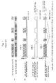
- Patent Literature 1 for example, as shown in FIG. 1 corresponding to FIG. 8 of Patent Literature 1, an absolute pattern signal ( FIG. 1C ) is separated off from a received light signal ( FIG. 8B ) by means of a low-pass filter.
- the employment of the low-pass filter leads to a longer signal processing time, thereby being unable to perform high-speed processing.
- the present invention has been made to solve the above-described problem of the conventional technique, and an object thereof is to achieve the separation of an absolute pattern signal and an incremental pattern signal in an ABS/INC integrated pattern at a high speed without employing a high-performance processing circuit.
- an absolute position measuring encoder having an absolute (ABS)/incremental (INC) integrated pattern obtained by integrating an absolute pattern and an incremental pattern together
- the encoder including: an imaging optical system designed to generate an amplitude difference between a light and dark signal derived from the absolute pattern and a light and dark signal derived from the incremental pattern; and a signal processing system for separating a received light signal from the ABS/INC integrated pattern into an absolute pattern signal and an incremental pattern signal by utilizing the amplitude difference.
- the absolute/incremental integrated pattern may be a pattern integrating the absolute pattern and the incremental pattern together in one track by arranging the incremental pattern having a predetermined pitch p INC at a position of the absolute pattern where a pseudo random pattern is arranged.
- the imaging optical system may include a lens designed to have an MTF (Modulation Transfer Function) curve so as to generate an amplitude difference between the light and dark signal derived from the absolute pattern and the light and dark signal derived from the incremental pattern.
- MTF Modulation Transfer Function
- the lens may have an MTF curve such that an amplitude (contrast) is large for a coarse absolute pattern and an amplitude (contrast) is small for a fine incremental pattern.
- the signal processing system may include an A/D converter for converting the received light signal into a multivalued digital signal.
- the received light signal may be separated by determining a threshold by means of the amplitude difference and binarizing the received light signal.
- the absolute pattern signal can be separated off by determining the threshold as an intermediate value between a minimum value of the light and dark signal derived from the absolute pattern and a minimum value of the light and dark signal derived from the incremental pattern, and binarizing the received light signal.
- the absolute pattern signal can be separated off by determining the threshold as an intermediate value between a maximum value of the light and dark signal derived from the incremental pattern and a maximum value of the light and dark signal derived from the absolute pattern, and binarizing the received light signal.
- the incremental pattern signal can be separated off by determining the threshold as an intermediate value between a minimum value and a maximum value of the light and dark signal derived from the incremental pattern, and binarizing the received light signal.
- the signal processing system may include: an absolute position detecting circuit for detecting an absolute position by processing the light and dark signal derived from the absolute pattern; a relative position detecting circuit for detecting a relative position by processing the incremental pattern signal; and an absolute position synthesizing circuit for combining outputs of the absolute position detecting circuit and the relative position detecting circuit together so as to output an absolute position signal interpolated by the relative position.
- the absolute position measuring encoder may be of a reflective type such that a light source and a lens are arranged on the same side with respect to a scale and a pattern signal component corresponds to a dark portion on the scale.
- the absolute position measuring encoder may be of a transmission type such that a light source is arranged on a side opposite to a lens with respect to a scale and a pattern light portion corresponds to a signal component.
- the threshold of the absolute pattern and the threshold of the incremental pattern can be determined by capturing an image of the ABS/INC integrated pattern by means of the appropriately designed imaging optical system.
- the binarization processes based on the derived thresholds make it possible to separate both of the absolute pattern signal and the incremental pattern signal easily and quickly. According to this method, no complicated operation is required, thereby eliminating the need for a high-performance processing circuit and further achieving a reduction in an operation time thereof.
- the absolute position measuring encoder includes: a light source 10; a reflective type scale 12 having an ABS/INC integrated pattern 12C, onto which light from the light source 10 is irradiated; a lens 14 designed to have an MTF (Modulation Transfer Function) curve so as to generate an amplitude difference between a light and dark signal derived from an absolute pattern and a light and dark signal derived from an incremental pattern; a light receiving element (for example, a photodiode array) 16 for receiving reflected light from the scale 12 through the lens 14; an A/D converter 18 for converting a light and dark signal, which is an output from the light receiving element 16, into a multivalued (for example, 256 values) digital signal; a comparator 20 for comparing a light and dark level signal, which is an MTF (Modulation Transfer Function) curve so as to generate an amplitude difference between a light and dark signal derived from an absolute pattern and a light and dark signal derived from an incremental pattern; a light receiving element (for example, a photodio
- an incremental (INC) pattern 12B having a predetermined pitch p INC as shown in FIG. 3B is arranged at a position of an absolute (ABS) pattern 12A where a pseudo random pattern is arranged as shown in FIG. 3A so as to obtain the ABS/INC integrated pattern 12C arranged on the scale 12 as shown in FIG. 3C and integrating the ABS pattern 12A and the INC pattern 12B together in one track.
- ABS absolute
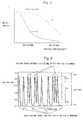
- the lens 14 has an MTF curve such that an amplitude (contrast) is large for a coarse ABS pattern and an amplitude (contrast) is small for a fine INC pattern as the MTF curve (representing how precisely an object contrast can be reproduced as spatial frequency characteristics) thereof is exemplified by a solid line A in FIG. 4 .
- a lens having an MTF curve as shown by a broken line B is typically used so as to obtain a high resolution even in a fine INC pattern
- the present invention employs the lens having the MTF curve as shown by the solid line A so as to reduce the amplitude of the INC pattern (lower the resolving power thereof) only.
- an absolute pattern signal can be obtained as shown in FIG. 6 by determining the ABS pattern threshold S ABS for separating off the absolute pattern as an intermediate value S ABS between the minimum value A ABS-L of the light and dark signal derived from the absolute pattern and the minimum value A INC-L of the light and dark signal derived from the incremental pattern, i.e., A ABS-L ⁇ S ABS ⁇ A INC-L , and binarizing the received light signal.
- an incremental pattern signal can be obtained by determining the INC pattern threshold S INC for separating off the incremental pattern as an intermediate value between the minimum value A INC-L and the maximum value A INC-H of the light and dark signal derived from the incremental pattern, i.e., A INC-L ⁇ S INC ⁇ A INC-H , and binarizing the received light signal.
- the thus obtained absolute pattern signal and incremental pattern signal are sent to the absolute position detecting circuit 22 and the relative position detecting circuit 24 so as to obtain an absolute position signal and a relative position signal, respectively. Then, by combining these signals at the absolute position combining circuit 26, it is possible to obtain an absolute position by the absolute position signal interpolated by the relative position signal. Note that since the configurations and functions of the absolute position detecting circuit 22, the relative position detecting circuit 24, and the absolute position synthesizing circuit 26 are the same as those in Patent Literature 1, the detailed description thereof will be omitted. Moreover, a reduction in accuracy resulting from the arrangement of the incremental pattern only at the absolute pattern position can be compensated for by the fitting of a sinusoidal function as described in Japanese Patent Application Laid-Open No. 2010-48607 , for example.
- the present invention is applied to the reflective type encoder so that a pattern dark portion includes a signal component in the present embodiment
- the application subject of the present invention is not limited thereto.
- the present invention can be similarly applied to a transmission type encoder such that the light source 10 is arranged on a side opposite to the lens 14 and a pattern light portion includes a signal component as in the second embodiment shown in FIG. 7 .
- an amplitude difference between the light and dark signal derived from the absolute pattern and the light and dark signal derived from the incremental pattern is as shown in FIG. 8 .
- an absolute pattern signal can be obtained as exemplified in FIG. 9 .
- the threshold S INC same as that in the first embodiment can be used in order to separate an incremental pattern signal off.
- the absolute pattern is arranged according to the pseudo random pattern in each of the above-described embodiments, the arrangement of the absolute pattern is not limited thereto.
- the imaging optical system is configured by a single lens in the above-described embodiments, the configuration of the imaging optical system is not limited thereto.
Landscapes
- Physics & Mathematics (AREA)
- General Physics & Mathematics (AREA)
- Optical Transform (AREA)
- Length Measuring Devices By Optical Means (AREA)
Abstract
Description
- The present invention relates to an absolute position measuring encoder having an absolute (referred to also as ABS) /incremental (referred to also as INC) integrated pattern obtained by integrating an absolute pattern and an incremental pattern together. In particular, the present invention relates to an absolute position measuring encoder capable of separating a received light signal from the ABS/INC integrated pattern into an absolute pattern signal and an incremental pattern signal in a short operation time without employing a high-performance processing circuit.
- An absolute position measuring encoder having an ABS/INC integrated pattern obtained by integrating an absolute pattern and an incremental pattern together has been suggested in the second and fourth embodiments of Japanese Patent Application Laid-Open No.
2009-2702 - However, since the ABS/INC integrated pattern has two types of information about an absolute pattern signal and an incremental pattern signal, a complicated analysis is required in order to separate these two types of information from each other. Thus, there is a problem that a high-performance processing circuit is required or a long operation time is needed. In
Patent Literature 1, for example, as shown inFIG. 1 corresponding toFIG. 8 ofPatent Literature 1, an absolute pattern signal (FIG. 1C ) is separated off from a received light signal (FIG. 8B ) by means of a low-pass filter. However, the employment of the low-pass filter leads to a longer signal processing time, thereby being unable to perform high-speed processing. - The present invention has been made to solve the above-described problem of the conventional technique, and an object thereof is to achieve the separation of an absolute pattern signal and an incremental pattern signal in an ABS/INC integrated pattern at a high speed without employing a high-performance processing circuit.
- The present invention achieves the above-described object by an absolute position measuring encoder having an absolute (ABS)/incremental (INC) integrated pattern obtained by integrating an absolute pattern and an incremental pattern together, the encoder including: an imaging optical system designed to generate an amplitude difference between a light and dark signal derived from the absolute pattern and a light and dark signal derived from the incremental pattern; and a signal processing system for separating a received light signal from the ABS/INC integrated pattern into an absolute pattern signal and an incremental pattern signal by utilizing the amplitude difference.
- Here, the absolute/incremental integrated pattern may be a pattern integrating the absolute pattern and the incremental pattern together in one track by arranging the incremental pattern having a predetermined pitch pINC at a position of the absolute pattern where a pseudo random pattern is arranged.
- Moreover, the imaging optical system may include a lens designed to have an MTF (Modulation Transfer Function) curve so as to generate an amplitude difference between the light and dark signal derived from the absolute pattern and the light and dark signal derived from the incremental pattern.
- Moreover, the lens may have an MTF curve such that an amplitude (contrast) is large for a coarse absolute pattern and an amplitude (contrast) is small for a fine incremental pattern.
- Moreover, the signal processing system may include an A/D converter for converting the received light signal into a multivalued digital signal.
- Moreover, the received light signal may be separated by determining a threshold by means of the amplitude difference and binarizing the received light signal.
- Moreover, the absolute pattern signal can be separated off by determining the threshold as an intermediate value between a minimum value of the light and dark signal derived from the absolute pattern and a minimum value of the light and dark signal derived from the incremental pattern, and binarizing the received light signal.
- Alternatively, the absolute pattern signal can be separated off by determining the threshold as an intermediate value between a maximum value of the light and dark signal derived from the incremental pattern and a maximum value of the light and dark signal derived from the absolute pattern, and binarizing the received light signal.
- Moreover, the incremental pattern signal can be separated off by determining the threshold as an intermediate value between a minimum value and a maximum value of the light and dark signal derived from the incremental pattern, and binarizing the received light signal.
- Moreover, the signal processing system may include: an absolute position detecting circuit for detecting an absolute position by processing the light and dark signal derived from the absolute pattern; a relative position detecting circuit for detecting a relative position by processing the incremental pattern signal; and an absolute position synthesizing circuit for combining outputs of the absolute position detecting circuit and the relative position detecting circuit together so as to output an absolute position signal interpolated by the relative position.
- Moreover, the absolute position measuring encoder may be of a reflective type such that a light source and a lens are arranged on the same side with respect to a scale and a pattern signal component corresponds to a dark portion on the scale.
- Moreover, the absolute position measuring encoder may be of a transmission type such that a light source is arranged on a side opposite to a lens with respect to a scale and a pattern light portion corresponds to a signal component.
- According to the present invention, the threshold of the absolute pattern and the threshold of the incremental pattern can be determined by capturing an image of the ABS/INC integrated pattern by means of the appropriately designed imaging optical system. Thus, the binarization processes based on the derived thresholds make it possible to separate both of the absolute pattern signal and the incremental pattern signal easily and quickly. According to this method, no complicated operation is required, thereby eliminating the need for a high-performance processing circuit and further achieving a reduction in an operation time thereof.
- These and other novel features and advantages of the present invention will become apparent from the following detailed description of preferred embodiments.
- The preferred embodiments will be described with reference to the drawings, wherein like elements have been denoted throughout the figures with like reference numerals, and wherein:
-
FIG. 1 shows time charts representing an outline of the conventional technique described inPatent Literature 1; -
FIG. 2 is a cross-sectional view showing the entire configuration of an absolute position measuring encoder according to a first embodiment of the present invention applied to a reflective type encoder; -
FIG. 3 is a plan view showing an ABS/INC integrated pattern according to the first embodiment; -
FIG. 4 is a graph showing an exemplary MTF curve of an imaging optical system according to the first embodiment; -
FIG. 5 is a diagram showing an exemplary amplitude difference between a light and dark signal derived from an absolute pattern and a light and dark signal derived from an incremental pattern according to the first embodiment; -
FIG. 6 shows diagrams illustrating thresholds determined by means of the amplitude difference inFIG. 5 and examples of scale pattern signals obtained by binarization by means of the thresholds; -
FIG. 7 is a cross-sectional view showing the entire configuration of an absolute position measuring encoder according to a second embodiment of the present invention applied to a transmission type encoder; -
FIG. 8 is a diagram showing an exemplary amplitude difference between a light and dark signal derived from an absolute pattern and a light and dark signal derived from an incremental pattern according to the second embodiment; and -
FIG. 9 shows diagrams illustrating thresholds determined by means of the amplitude difference inFIG. 7 and examples of scale pattern signals obtained by binarization by means of the thresholds. - Hereinafter, exemplary embodiments of the present invention will be described in detail with reference to the drawings.
- As the entire configuration thereof is shown in
FIG. 2 , the first embodiment of the present invention is obtained by applying the present invention to an absolute position measuring encoder of a reflective type in which a pattern signal component corresponds to a dark portion on a scale, for example. The absolute position measuring encoder includes: alight source 10; areflective type scale 12 having an ABS/INC integratedpattern 12C, onto which light from thelight source 10 is irradiated; alens 14 designed to have an MTF (Modulation Transfer Function) curve so as to generate an amplitude difference between a light and dark signal derived from an absolute pattern and a light and dark signal derived from an incremental pattern; a light receiving element (for example, a photodiode array) 16 for receiving reflected light from thescale 12 through thelens 14; an A/D converter 18 for converting a light and dark signal, which is an output from thelight receiving element 16, into a multivalued (for example, 256 values) digital signal; acomparator 20 for comparing a light and dark level signal, which is an output from the A/D converter 18, with a threshold SABS of the absolute pattern and a threshold SINC of the incremental pattern; an absoluteposition detecting circuit 22 for detecting an absolute position by processing an absolute (ABS) pattern signal obtained by thecomparator 20; a relativeposition detecting circuit 24 for detecting a relative position by processing an incremental (INC) pattern signal obtained by thecomparator 20; and an absoluteposition combining circuit 26 for combining outputs of the absoluteposition detecting circuit 22 and the relativeposition detecting circuit 24 together so as to output an absolute position signal interpolated by the relative position. - For example, an incremental (INC)
pattern 12B having a predetermined pitch pINC as shown inFIG. 3B is arranged at a position of an absolute (ABS) pattern 12A where a pseudo random pattern is arranged as shown inFIG. 3A so as to obtain the ABS/INC integratedpattern 12C arranged on thescale 12 as shown inFIG. 3C and integrating the ABS pattern 12A and theINC pattern 12B together in one track. - The
lens 14 has an MTF curve such that an amplitude (contrast) is large for a coarse ABS pattern and an amplitude (contrast) is small for a fine INC pattern as the MTF curve (representing how precisely an object contrast can be reproduced as spatial frequency characteristics) thereof is exemplified by a solid line A inFIG. 4 . In other words, whereas a lens having an MTF curve as shown by a broken line B is typically used so as to obtain a high resolution even in a fine INC pattern, the present invention employs the lens having the MTF curve as shown by the solid line A so as to reduce the amplitude of the INC pattern (lower the resolving power thereof) only. - If an image of the ABS/INC integrated
pattern 12C is captured by such alens 14, the amplitude A of the resultant light and dark signal reaches its maximum value A = AINC at a position where a pattern (INC pattern) is arranged with the pitch pINC (the light and dark signal derived from the INC pattern) as exemplified inFIG. 5 . On the other hand, at a position where a pattern is not arranged with the pitch pINC (the light and dark signal derived from the ABS pattern), the amplitude thereof becomes A = AABS (> AINC). In other words, the following relationships hold true: - (the minimum value AABS-L of the light and dark signal derived from the ABS pattern) < (the minimum value AINC-L of the light and dark signal derived from the INC pattern), and
- (the maximum value AINC-H of the light and dark signal derived from the INC pattern) < (the maximum value AABS-H of the light and dark signal derived from the ABS pattern).
- Therefore, by utilizing a difference between AABS-L and AINC-L, for example, an absolute pattern signal can be obtained as shown in
FIG. 6 by determining the ABS pattern threshold SABS for separating off the absolute pattern as an intermediate value SABS between the minimum value AABS-L of the light and dark signal derived from the absolute pattern and the minimum value AINC-L of the light and dark signal derived from the incremental pattern, i.e., AABS-L < SABS < AINC-L, and binarizing the received light signal. - Also, an incremental pattern signal can be obtained by determining the INC pattern threshold SINC for separating off the incremental pattern as an intermediate value between the minimum value AINC-L and the maximum value AINC-H of the light and dark signal derived from the incremental pattern, i.e., AINC-L < SINC < AINC-H, and binarizing the received light signal.
- The thus obtained absolute pattern signal and incremental pattern signal are sent to the absolute
position detecting circuit 22 and the relativeposition detecting circuit 24 so as to obtain an absolute position signal and a relative position signal, respectively. Then, by combining these signals at the absoluteposition combining circuit 26, it is possible to obtain an absolute position by the absolute position signal interpolated by the relative position signal. Note that since the configurations and functions of the absoluteposition detecting circuit 22, the relativeposition detecting circuit 24, and the absoluteposition synthesizing circuit 26 are the same as those inPatent Literature 1, the detailed description thereof will be omitted. Moreover, a reduction in accuracy resulting from the arrangement of the incremental pattern only at the absolute pattern position can be compensated for by the fitting of a sinusoidal function as described in Japanese Patent Application Laid-Open No.2010-48607 - Note that while the present invention is applied to the reflective type encoder so that a pattern dark portion includes a signal component in the present embodiment, the application subject of the present invention is not limited thereto. The present invention can be similarly applied to a transmission type encoder such that the
light source 10 is arranged on a side opposite to thelens 14 and a pattern light portion includes a signal component as in the second embodiment shown inFIG. 7 . - In the present embodiment, an amplitude difference between the light and dark signal derived from the absolute pattern and the light and dark signal derived from the incremental pattern is as shown in
FIG. 8 . - Thus, by setting the threshold SABS for separating off the absolute pattern to an intermediate value between the maximum value AINC-H of the light and dark signal derived from the incremental pattern and the maximum value AABS-H of the light and dark signal derived from the absolute pattern, i.e., AINC-H < SABS < AABS-H, an absolute pattern signal can be obtained as exemplified in
FIG. 9 . Note that the threshold SINC same as that in the first embodiment can be used in order to separate an incremental pattern signal off. - Since the other respects are the same as those in the first embodiment, the same reference numerals are used for those respects, respectively, and the description thereof will be omitted.
- Note that while the absolute pattern is arranged according to the pseudo random pattern in each of the above-described embodiments, the arrangement of the absolute pattern is not limited thereto.
- Moreover, while the imaging optical system is configured by a single lens in the above-described embodiments, the configuration of the imaging optical system is not limited thereto.
Claims (12)
- An absolute position measuring encoder having an absolute/incremental integrated pattern obtained by integrating an absolute pattern and an incremental pattern together, the absolute position measuring encoder comprising:an imaging optical system designed to generate an amplitude difference between a light and dark signal derived from the absolute pattern and a light and dark signal derived from the incremental pattern; anda signal processing system for separating a received light signal from the absolute/incremental integrated pattern into an absolute pattern signal and an incremental pattern signal by utilizing the amplitude difference.
- The absolute position measuring encoder according to claim 1, wherein the absolute/incremental integrated pattern is a pattern integrating the absolute pattern and the incremental pattern together in one track by arranging the incremental pattern having a predetermined pitch pINC at a position of the absolute pattern where a pseudo random pattern is arranged.
- The absolute position measuring encoder according to claim 1 or claim 2, wherein the imaging optical system includes a lens designed to have an MTF (Modulation Transfer Function) curve so as to generate an amplitude difference between the light and dark signal derived from the absolute pattern and the light and dark signal derived from the incremental pattern.
- The absolute position measuring encoder according to claim 3, wherein the lens has an MTF curve such that an amplitude (contrast) is large for a coarse absolute pattern and an amplitude (contrast) is small for a fine incremental pattern.
- The absolute position measuring encoder according to any of the preceding claims, wherein the signal processing system includes an A/D converter for converting the received light signal into a multivalued digital signal.
- The absolute position measuring encoder according to any of the preceding claims, wherein the received light signal is separated by determining a threshold by means of the amplitude difference and binarizing the received light signal.
- The absolute position measuring encoder according to claim 6, wherein the absolute pattern signal is separated off by determining the threshold as an intermediate value between a minimum value of the light and dark signal derived from the absolute pattern and a minimum value of the light and dark signal derived from the incremental pattern and binarizing the received light signal.
- The absolute position measuring encoder according to claim 6, wherein the absolute pattern signal is separated off by determining the threshold as an intermediate value between a maximum value of the light and dark signal derived from the incremental pattern and a maximum value of the light and dark signal derived from the absolute pattern and binarizing the received light signal.
- The absolute position measuring encoder according to claim 6, wherein the incremental pattern signal is separated off by determining the threshold as an intermediate value between a minimum value and a maximum value of the light and dark signal derived from the incremental pattern and binarizing the received light signal.
- The absolute position measuring encoder according to any of the preceding claims wherein the signal processing system includes: an absolute position detecting circuit for detecting an absolute position by processing the light and dark signal derived from the absolute pattern; a relative position detecting circuit for detecting a relative position by processing the incremental pattern signal; and an absolute position synthesizing circuit for combining outputs of the absolute position detecting circuit and the relative position detecting circuit together so as to output an absolute position signal interpolated by the relative position.
- The absolute position measuring encoder according to any of the preceding claims, wherein the absolute position measuring encoder is of a reflective type such that a light source and a lens are arranged on the same side with respect to a scale and a pattern signal component corresponds to a dark portion on the scale.
- The absolute position measuring encoder according to any of claims 1 to 10, wherein the absolute position measuring encoder is of a transmission type such that a light source is arranged on a side opposite to a lens with respect to a scale and a pattern light portion corresponds to a signal component.
Applications Claiming Priority (1)
| Application Number | Priority Date | Filing Date | Title |
|---|---|---|---|
| JP2011191027A JP5829464B2 (en) | 2011-09-01 | 2011-09-01 | Absolute length encoder |
Publications (2)
| Publication Number | Publication Date |
|---|---|
| EP2565590A1 true EP2565590A1 (en) | 2013-03-06 |
| EP2565590B1 EP2565590B1 (en) | 2015-02-25 |
Family
ID=46826267
Family Applications (1)
| Application Number | Title | Priority Date | Filing Date |
|---|---|---|---|
| EP12182460.1A Active EP2565590B1 (en) | 2011-09-01 | 2012-08-30 | Absolute position measuring encoder |
Country Status (4)
| Country | Link |
|---|---|
| US (1) | US8809764B2 (en) |
| EP (1) | EP2565590B1 (en) |
| JP (1) | JP5829464B2 (en) |
| CN (1) | CN102967321B (en) |
Cited By (3)
| Publication number | Priority date | Publication date | Assignee | Title |
|---|---|---|---|---|
| EP2878928A1 (en) * | 2013-11-29 | 2015-06-03 | Canon Kabushiki Kaisha | Absolute encoder, signal processing method, program, driving apparatus, and industrial machine |
| CN106152888A (en) * | 2014-08-22 | 2016-11-23 | 株式会社三丰 | There is in stacking construction the absolute position encoder scale of each layer |
| CN107525530A (en) * | 2017-08-08 | 2017-12-29 | 吉林大学 | A kind of integrated circuit of absolute optical encoder |
Families Citing this family (12)
| Publication number | Priority date | Publication date | Assignee | Title |
|---|---|---|---|---|
| EP2671054A1 (en) * | 2011-01-31 | 2013-12-11 | Witeg Labortechnik GmbH | Bottle dispenser having a digital volume display |
| JP5829464B2 (en) * | 2011-09-01 | 2015-12-09 | 株式会社ミツトヨ | Absolute length encoder |
| US20140002642A1 (en) | 2012-06-15 | 2014-01-02 | Elmar SWIEGOT | Absolute position detection |
| JP6533360B2 (en) * | 2013-10-30 | 2019-06-19 | キヤノン株式会社 | Position detection device, lens apparatus having the same, and imaging apparatus |
| JP6366274B2 (en) * | 2014-01-07 | 2018-08-01 | キヤノン株式会社 | Scale, measuring apparatus, image forming apparatus, scale processing apparatus, and scale processing method |
| CN105675030B (en) * | 2016-03-23 | 2017-10-17 | 北京天诚同创电气有限公司 | Measuring method and device for absolute value encoder |
| JP6879776B2 (en) * | 2017-02-24 | 2021-06-02 | アズビル株式会社 | Rotation control device |
| TWI646311B (en) * | 2018-01-02 | 2019-01-01 | 大銀微系統股份有限公司 | Optical coding sensing device |
| CN108981764A (en) * | 2018-05-04 | 2018-12-11 | 广东工业大学 | A kind of rotating grating encoder rotating angle measurement apparatus and method |
| US10963724B2 (en) * | 2019-04-01 | 2021-03-30 | Novanta Corporation | Absolute position encoder using a focused laser beam to detect position code words |
| CN110207596B (en) * | 2019-06-21 | 2021-09-03 | 广东工业大学 | Image coding method, grating ruler measuring device and measuring method |
| JPWO2022044753A1 (en) * | 2020-08-25 | 2022-03-03 |
Citations (4)
| Publication number | Priority date | Publication date | Assignee | Title |
|---|---|---|---|---|
| JP2009002702A (en) | 2007-06-19 | 2009-01-08 | Mitsutoyo Corp | Absolute position measuring encoder |
| EP2093543A2 (en) * | 2008-02-21 | 2009-08-26 | Mitutoyo Corporation | Photoelectric Encoder and Scale |
| EP2120019A2 (en) * | 2008-05-13 | 2009-11-18 | Mitutoyo Corporation | Absolute position length measurement type encoder |
| JP2010048607A (en) | 2008-08-20 | 2010-03-04 | Mitsutoyo Corp | Photoelectric encoder |
Family Cites Families (11)
| Publication number | Priority date | Publication date | Assignee | Title |
|---|---|---|---|---|
| DE50009018D1 (en) * | 1999-11-18 | 2005-01-27 | Hera Rotterdam Bv | position sensor |
| US6664535B1 (en) * | 2002-07-16 | 2003-12-16 | Mitutoyo Corporation | Scale structures and methods usable in an absolute position transducer |
| US6867412B2 (en) * | 2002-11-12 | 2005-03-15 | Mitutoyo Corporation | Scale structures and methods usable in an absolute position transducer |
| US7365917B2 (en) * | 2004-08-16 | 2008-04-29 | Xceed Imaging Ltd. | Optical method and system for extended depth of focus |
| US7835630B2 (en) * | 2007-04-06 | 2010-11-16 | The Johns Hopkins University | Adaptive and reconfigurable system for DC motor control |
| JP4960133B2 (en) * | 2007-04-11 | 2012-06-27 | 株式会社ミツトヨ | Absolute position measuring encoder |
| JP2008294302A (en) * | 2007-05-25 | 2008-12-04 | Canon Inc | Alignment apparatus and alignment method, exposure apparatus, and device manufacturing method |
| US8493572B2 (en) * | 2010-05-05 | 2013-07-23 | Mitutoyo Corporation | Optical encoder having contamination and defect resistant signal processing |
| JP5616741B2 (en) * | 2010-10-08 | 2014-10-29 | 株式会社ミツトヨ | Encoder |
| JP5829464B2 (en) * | 2011-09-01 | 2015-12-09 | 株式会社ミツトヨ | Absolute length encoder |
| JP6074672B2 (en) * | 2011-10-28 | 2017-02-08 | 株式会社ミツトヨ | Displacement detection device, displacement detection method, and displacement detection program |
-
2011
- 2011-09-01 JP JP2011191027A patent/JP5829464B2/en active Active
-
2012
- 2012-08-29 US US13/597,803 patent/US8809764B2/en active Active
- 2012-08-30 EP EP12182460.1A patent/EP2565590B1/en active Active
- 2012-09-03 CN CN201210322653.2A patent/CN102967321B/en active Active
Patent Citations (4)
| Publication number | Priority date | Publication date | Assignee | Title |
|---|---|---|---|---|
| JP2009002702A (en) | 2007-06-19 | 2009-01-08 | Mitsutoyo Corp | Absolute position measuring encoder |
| EP2093543A2 (en) * | 2008-02-21 | 2009-08-26 | Mitutoyo Corporation | Photoelectric Encoder and Scale |
| EP2120019A2 (en) * | 2008-05-13 | 2009-11-18 | Mitutoyo Corporation | Absolute position length measurement type encoder |
| JP2010048607A (en) | 2008-08-20 | 2010-03-04 | Mitsutoyo Corp | Photoelectric encoder |
Cited By (5)
| Publication number | Priority date | Publication date | Assignee | Title |
|---|---|---|---|---|
| EP2878928A1 (en) * | 2013-11-29 | 2015-06-03 | Canon Kabushiki Kaisha | Absolute encoder, signal processing method, program, driving apparatus, and industrial machine |
| US9417102B2 (en) | 2013-11-29 | 2016-08-16 | Canon Kabushiki Kaisha | Absolute encoder, signal processing method, program, driving apparatus, and industrial machine |
| CN106152888A (en) * | 2014-08-22 | 2016-11-23 | 株式会社三丰 | There is in stacking construction the absolute position encoder scale of each layer |
| CN106152888B (en) * | 2014-08-22 | 2019-02-15 | 株式会社三丰 | With the absolute position encoder scale of each layer in stacking construction |
| CN107525530A (en) * | 2017-08-08 | 2017-12-29 | 吉林大学 | A kind of integrated circuit of absolute optical encoder |
Also Published As
| Publication number | Publication date |
|---|---|
| JP5829464B2 (en) | 2015-12-09 |
| EP2565590B1 (en) | 2015-02-25 |
| CN102967321B (en) | 2016-02-24 |
| CN102967321A (en) | 2013-03-13 |
| JP2013053880A (en) | 2013-03-21 |
| US20130056624A1 (en) | 2013-03-07 |
| US8809764B2 (en) | 2014-08-19 |
Similar Documents
| Publication | Publication Date | Title |
|---|---|---|
| EP2565590B1 (en) | Absolute position measuring encoder | |
| JP5740413B2 (en) | Demodulation sensor with separate pixel array and storage array | |
| EP2150041B1 (en) | Image reading device and image forming apparatus | |
| US10298866B2 (en) | Photoelectric conversion element, image reading device, image forming apparatus, image reading method, and computer-readable recording medium | |
| EP2093543A2 (en) | Photoelectric Encoder and Scale | |
| KR102112298B1 (en) | Method and apparatus for generating color image and depth image | |
| EP3035003B1 (en) | Position detection apparatus, lens apparatus, image pickup system, machine tool apparatus, position detection method, program, and storage medium | |
| CN102016636A (en) | Distance measuring device, distance measuring method, program and integrated circuit | |
| EP2365291B1 (en) | Photoelectric encoder | |
| US20160363462A1 (en) | Systems, circuits and methods for determining a position of a movable object | |
| US11754717B2 (en) | Distance measurement device having external light illuminance measurement function and external light illuminance measurement method | |
| US20130188084A1 (en) | Apparatus and method for improving contrast detected in a fringe projection autofocus system | |
| CN110672136B (en) | Signal processing method for photoelectric encoder | |
| US7856126B2 (en) | Position sensing device | |
| EP3538849B1 (en) | Contactless angular sensor | |
| US9157769B2 (en) | Reference signal generation apparatus and reference signal generation system | |
| CN113820014A (en) | Light intensity calibration method and system based on scanning grating micro-mirror spectrometer and spectrometer | |
| JPS59123367A (en) | Image reading method | |
| JPS6393279A (en) | Focus detection device | |
| JP2675079B2 (en) | Binarization processing circuit | |
| KR200405415Y1 (en) | Dual system camera with half mirror | |
| KR20260072671A (en) | Signal processing device and method for high-resolution multi-channel 3D lidar | |
| JP6819428B2 (en) | Image imager | |
| JP4599182B2 (en) | Photoelectric sensor | |
| JPH0562502B2 (en) |
Legal Events
| Date | Code | Title | Description |
|---|---|---|---|
| PUAI | Public reference made under article 153(3) epc to a published international application that has entered the european phase |
Free format text: ORIGINAL CODE: 0009012 |
|
| AK | Designated contracting states |
Kind code of ref document: A1 Designated state(s): AL AT BE BG CH CY CZ DE DK EE ES FI FR GB GR HR HU IE IS IT LI LT LU LV MC MK MT NL NO PL PT RO RS SE SI SK SM TR |
|
| AX | Request for extension of the european patent |
Extension state: BA ME |
|
| 17P | Request for examination filed |
Effective date: 20130614 |
|
| RBV | Designated contracting states (corrected) |
Designated state(s): AL AT BE BG CH CY CZ DE DK EE ES FI FR GB GR HR HU IE IS IT LI LT LU LV MC MK MT NL NO PL PT RO RS SE SI SK SM TR |
|
| GRAP | Despatch of communication of intention to grant a patent |
Free format text: ORIGINAL CODE: EPIDOSNIGR1 |
|
| INTG | Intention to grant announced |
Effective date: 20141113 |
|
| RIN1 | Information on inventor provided before grant (corrected) |
Inventor name: KATO, YOSHIAKI |
|
| GRAS | Grant fee paid |
Free format text: ORIGINAL CODE: EPIDOSNIGR3 |
|
| GRAA | (expected) grant |
Free format text: ORIGINAL CODE: 0009210 |
|
| AK | Designated contracting states |
Kind code of ref document: B1 Designated state(s): AL AT BE BG CH CY CZ DE DK EE ES FI FR GB GR HR HU IE IS IT LI LT LU LV MC MK MT NL NO PL PT RO RS SE SI SK SM TR |
|
| REG | Reference to a national code |
Ref country code: GB Ref legal event code: FG4D |
|
| REG | Reference to a national code |
Ref country code: CH Ref legal event code: EP |
|
| REG | Reference to a national code |
Ref country code: IE Ref legal event code: FG4D |
|
| REG | Reference to a national code |
Ref country code: DE Ref legal event code: R096 Ref document number: 602012005410 Country of ref document: DE Effective date: 20150409 |
|
| REG | Reference to a national code |
Ref country code: AT Ref legal event code: REF Ref document number: 712361 Country of ref document: AT Kind code of ref document: T Effective date: 20150415 |
|
| REG | Reference to a national code |
Ref country code: NL Ref legal event code: VDEP Effective date: 20150225 |
|
| REG | Reference to a national code |
Ref country code: AT Ref legal event code: MK05 Ref document number: 712361 Country of ref document: AT Kind code of ref document: T Effective date: 20150225 |
|
| REG | Reference to a national code |
Ref country code: LT Ref legal event code: MG4D |
|
| PG25 | Lapsed in a contracting state [announced via postgrant information from national office to epo] |
Ref country code: HR Free format text: LAPSE BECAUSE OF FAILURE TO SUBMIT A TRANSLATION OF THE DESCRIPTION OR TO PAY THE FEE WITHIN THE PRESCRIBED TIME-LIMIT Effective date: 20150225 Ref country code: FI Free format text: LAPSE BECAUSE OF FAILURE TO SUBMIT A TRANSLATION OF THE DESCRIPTION OR TO PAY THE FEE WITHIN THE PRESCRIBED TIME-LIMIT Effective date: 20150225 Ref country code: SE Free format text: LAPSE BECAUSE OF FAILURE TO SUBMIT A TRANSLATION OF THE DESCRIPTION OR TO PAY THE FEE WITHIN THE PRESCRIBED TIME-LIMIT Effective date: 20150225 Ref country code: ES Free format text: LAPSE BECAUSE OF FAILURE TO SUBMIT A TRANSLATION OF THE DESCRIPTION OR TO PAY THE FEE WITHIN THE PRESCRIBED TIME-LIMIT Effective date: 20150225 Ref country code: NO Free format text: LAPSE BECAUSE OF FAILURE TO SUBMIT A TRANSLATION OF THE DESCRIPTION OR TO PAY THE FEE WITHIN THE PRESCRIBED TIME-LIMIT Effective date: 20150525 Ref country code: LT Free format text: LAPSE BECAUSE OF FAILURE TO SUBMIT A TRANSLATION OF THE DESCRIPTION OR TO PAY THE FEE WITHIN THE PRESCRIBED TIME-LIMIT Effective date: 20150225 |
|
| PG25 | Lapsed in a contracting state [announced via postgrant information from national office to epo] |
Ref country code: AT Free format text: LAPSE BECAUSE OF FAILURE TO SUBMIT A TRANSLATION OF THE DESCRIPTION OR TO PAY THE FEE WITHIN THE PRESCRIBED TIME-LIMIT Effective date: 20150225 Ref country code: RS Free format text: LAPSE BECAUSE OF FAILURE TO SUBMIT A TRANSLATION OF THE DESCRIPTION OR TO PAY THE FEE WITHIN THE PRESCRIBED TIME-LIMIT Effective date: 20150225 Ref country code: LV Free format text: LAPSE BECAUSE OF FAILURE TO SUBMIT A TRANSLATION OF THE DESCRIPTION OR TO PAY THE FEE WITHIN THE PRESCRIBED TIME-LIMIT Effective date: 20150225 Ref country code: GR Free format text: LAPSE BECAUSE OF FAILURE TO SUBMIT A TRANSLATION OF THE DESCRIPTION OR TO PAY THE FEE WITHIN THE PRESCRIBED TIME-LIMIT Effective date: 20150526 Ref country code: IS Free format text: LAPSE BECAUSE OF FAILURE TO SUBMIT A TRANSLATION OF THE DESCRIPTION OR TO PAY THE FEE WITHIN THE PRESCRIBED TIME-LIMIT Effective date: 20150625 |
|
| PG25 | Lapsed in a contracting state [announced via postgrant information from national office to epo] |
Ref country code: NL Free format text: LAPSE BECAUSE OF FAILURE TO SUBMIT A TRANSLATION OF THE DESCRIPTION OR TO PAY THE FEE WITHIN THE PRESCRIBED TIME-LIMIT Effective date: 20150225 |
|
| PG25 | Lapsed in a contracting state [announced via postgrant information from national office to epo] |
Ref country code: EE Free format text: LAPSE BECAUSE OF FAILURE TO SUBMIT A TRANSLATION OF THE DESCRIPTION OR TO PAY THE FEE WITHIN THE PRESCRIBED TIME-LIMIT Effective date: 20150225 Ref country code: RO Free format text: LAPSE BECAUSE OF FAILURE TO SUBMIT A TRANSLATION OF THE DESCRIPTION OR TO PAY THE FEE WITHIN THE PRESCRIBED TIME-LIMIT Effective date: 20150225 Ref country code: DK Free format text: LAPSE BECAUSE OF FAILURE TO SUBMIT A TRANSLATION OF THE DESCRIPTION OR TO PAY THE FEE WITHIN THE PRESCRIBED TIME-LIMIT Effective date: 20150225 Ref country code: CZ Free format text: LAPSE BECAUSE OF FAILURE TO SUBMIT A TRANSLATION OF THE DESCRIPTION OR TO PAY THE FEE WITHIN THE PRESCRIBED TIME-LIMIT Effective date: 20150225 Ref country code: SK Free format text: LAPSE BECAUSE OF FAILURE TO SUBMIT A TRANSLATION OF THE DESCRIPTION OR TO PAY THE FEE WITHIN THE PRESCRIBED TIME-LIMIT Effective date: 20150225 |
|
| REG | Reference to a national code |
Ref country code: DE Ref legal event code: R097 Ref document number: 602012005410 Country of ref document: DE |
|
| PG25 | Lapsed in a contracting state [announced via postgrant information from national office to epo] |
Ref country code: PL Free format text: LAPSE BECAUSE OF FAILURE TO SUBMIT A TRANSLATION OF THE DESCRIPTION OR TO PAY THE FEE WITHIN THE PRESCRIBED TIME-LIMIT Effective date: 20150225 |
|
| PG25 | Lapsed in a contracting state [announced via postgrant information from national office to epo] |
Ref country code: IT Free format text: LAPSE BECAUSE OF FAILURE TO SUBMIT A TRANSLATION OF THE DESCRIPTION OR TO PAY THE FEE WITHIN THE PRESCRIBED TIME-LIMIT Effective date: 20150225 |
|
| PLBE | No opposition filed within time limit |
Free format text: ORIGINAL CODE: 0009261 |
|
| STAA | Information on the status of an ep patent application or granted ep patent |
Free format text: STATUS: NO OPPOSITION FILED WITHIN TIME LIMIT |
|
| 26N | No opposition filed |
Effective date: 20151126 |
|
| PG25 | Lapsed in a contracting state [announced via postgrant information from national office to epo] |
Ref country code: SI Free format text: LAPSE BECAUSE OF FAILURE TO SUBMIT A TRANSLATION OF THE DESCRIPTION OR TO PAY THE FEE WITHIN THE PRESCRIBED TIME-LIMIT Effective date: 20150225 |
|
| PG25 | Lapsed in a contracting state [announced via postgrant information from national office to epo] |
Ref country code: MC Free format text: LAPSE BECAUSE OF FAILURE TO SUBMIT A TRANSLATION OF THE DESCRIPTION OR TO PAY THE FEE WITHIN THE PRESCRIBED TIME-LIMIT Effective date: 20150225 Ref country code: LU Free format text: LAPSE BECAUSE OF FAILURE TO SUBMIT A TRANSLATION OF THE DESCRIPTION OR TO PAY THE FEE WITHIN THE PRESCRIBED TIME-LIMIT Effective date: 20150830 |
|
| REG | Reference to a national code |
Ref country code: CH Ref legal event code: PL |
|
| PG25 | Lapsed in a contracting state [announced via postgrant information from national office to epo] |
Ref country code: CH Free format text: LAPSE BECAUSE OF NON-PAYMENT OF DUE FEES Effective date: 20150831 Ref country code: LI Free format text: LAPSE BECAUSE OF NON-PAYMENT OF DUE FEES Effective date: 20150831 |
|
| PG25 | Lapsed in a contracting state [announced via postgrant information from national office to epo] |
Ref country code: BE Free format text: LAPSE BECAUSE OF FAILURE TO SUBMIT A TRANSLATION OF THE DESCRIPTION OR TO PAY THE FEE WITHIN THE PRESCRIBED TIME-LIMIT Effective date: 20150225 |
|
| REG | Reference to a national code |
Ref country code: IE Ref legal event code: MM4A |
|
| REG | Reference to a national code |
Ref country code: FR Ref legal event code: ST Effective date: 20160429 |
|
| PG25 | Lapsed in a contracting state [announced via postgrant information from national office to epo] |
Ref country code: IE Free format text: LAPSE BECAUSE OF NON-PAYMENT OF DUE FEES Effective date: 20150830 |
|
| PG25 | Lapsed in a contracting state [announced via postgrant information from national office to epo] |
Ref country code: FR Free format text: LAPSE BECAUSE OF NON-PAYMENT OF DUE FEES Effective date: 20150831 |
|
| PG25 | Lapsed in a contracting state [announced via postgrant information from national office to epo] |
Ref country code: MT Free format text: LAPSE BECAUSE OF FAILURE TO SUBMIT A TRANSLATION OF THE DESCRIPTION OR TO PAY THE FEE WITHIN THE PRESCRIBED TIME-LIMIT Effective date: 20150225 |
|
| PG25 | Lapsed in a contracting state [announced via postgrant information from national office to epo] |
Ref country code: BG Free format text: LAPSE BECAUSE OF FAILURE TO SUBMIT A TRANSLATION OF THE DESCRIPTION OR TO PAY THE FEE WITHIN THE PRESCRIBED TIME-LIMIT Effective date: 20150225 Ref country code: HU Free format text: LAPSE BECAUSE OF FAILURE TO SUBMIT A TRANSLATION OF THE DESCRIPTION OR TO PAY THE FEE WITHIN THE PRESCRIBED TIME-LIMIT; INVALID AB INITIO Effective date: 20120830 Ref country code: SM Free format text: LAPSE BECAUSE OF FAILURE TO SUBMIT A TRANSLATION OF THE DESCRIPTION OR TO PAY THE FEE WITHIN THE PRESCRIBED TIME-LIMIT Effective date: 20150225 |
|
| PG25 | Lapsed in a contracting state [announced via postgrant information from national office to epo] |
Ref country code: CY Free format text: LAPSE BECAUSE OF FAILURE TO SUBMIT A TRANSLATION OF THE DESCRIPTION OR TO PAY THE FEE WITHIN THE PRESCRIBED TIME-LIMIT Effective date: 20150225 |
|
| PG25 | Lapsed in a contracting state [announced via postgrant information from national office to epo] |
Ref country code: TR Free format text: LAPSE BECAUSE OF FAILURE TO SUBMIT A TRANSLATION OF THE DESCRIPTION OR TO PAY THE FEE WITHIN THE PRESCRIBED TIME-LIMIT Effective date: 20150225 |
|
| PG25 | Lapsed in a contracting state [announced via postgrant information from national office to epo] |
Ref country code: MK Free format text: LAPSE BECAUSE OF FAILURE TO SUBMIT A TRANSLATION OF THE DESCRIPTION OR TO PAY THE FEE WITHIN THE PRESCRIBED TIME-LIMIT Effective date: 20150225 Ref country code: PT Free format text: LAPSE BECAUSE OF FAILURE TO SUBMIT A TRANSLATION OF THE DESCRIPTION OR TO PAY THE FEE WITHIN THE PRESCRIBED TIME-LIMIT Effective date: 20150225 |
|
| PG25 | Lapsed in a contracting state [announced via postgrant information from national office to epo] |
Ref country code: AL Free format text: LAPSE BECAUSE OF FAILURE TO SUBMIT A TRANSLATION OF THE DESCRIPTION OR TO PAY THE FEE WITHIN THE PRESCRIBED TIME-LIMIT Effective date: 20150225 |
|
| PGFP | Annual fee paid to national office [announced via postgrant information from national office to epo] |
Ref country code: DE Payment date: 20250820 Year of fee payment: 14 |
|
| PGFP | Annual fee paid to national office [announced via postgrant information from national office to epo] |
Ref country code: GB Payment date: 20250821 Year of fee payment: 14 |