EP2565578B1 - Device for interferometric distance measurement between two parallel plates - Google Patents
Device for interferometric distance measurement between two parallel plates Download PDFInfo
- Publication number
- EP2565578B1 EP2565578B1 EP12177860.9A EP12177860A EP2565578B1 EP 2565578 B1 EP2565578 B1 EP 2565578B1 EP 12177860 A EP12177860 A EP 12177860A EP 2565578 B1 EP2565578 B1 EP 2565578B1
- Authority
- EP
- European Patent Office
- Prior art keywords
- plate
- deflection
- measurement
- light source
- diffractive
- Prior art date
- Legal status (The legal status is an assumption and is not a legal conclusion. Google has not performed a legal analysis and makes no representation as to the accuracy of the status listed.)
- Active
Links
- 238000005259 measurement Methods 0.000 title claims description 31
- 230000003287 optical effect Effects 0.000 claims description 65
- 238000001514 detection method Methods 0.000 claims description 22
- 238000006073 displacement reaction Methods 0.000 claims description 13
- 230000002452 interceptive effect Effects 0.000 claims description 6
- 230000000694 effects Effects 0.000 claims description 4
- 238000005305 interferometry Methods 0.000 claims 2
- 241000219739 Lens Species 0.000 description 44
- 230000005855 radiation Effects 0.000 description 10
- 239000011521 glass Substances 0.000 description 7
- 240000004322 Lens culinaris Species 0.000 description 4
- 238000000034 method Methods 0.000 description 3
- 241001295925 Gegenes Species 0.000 description 2
- 238000000576 coating method Methods 0.000 description 2
- 230000001419 dependent effect Effects 0.000 description 2
- 230000002349 favourable effect Effects 0.000 description 2
- 239000011248 coating agent Substances 0.000 description 1
- 230000007547 defect Effects 0.000 description 1
- 238000011156 evaluation Methods 0.000 description 1
- 238000000605 extraction Methods 0.000 description 1
- 239000000835 fiber Substances 0.000 description 1
- 239000000463 material Substances 0.000 description 1
- 230000005693 optoelectronics Effects 0.000 description 1
- 230000010363 phase shift Effects 0.000 description 1
- 230000001902 propagating effect Effects 0.000 description 1
- 238000005070 sampling Methods 0.000 description 1
Images


Classifications
-
- G—PHYSICS
- G01—MEASURING; TESTING
- G01B—MEASURING LENGTH, THICKNESS OR SIMILAR LINEAR DIMENSIONS; MEASURING ANGLES; MEASURING AREAS; MEASURING IRREGULARITIES OF SURFACES OR CONTOURS
- G01B9/00—Measuring instruments characterised by the use of optical techniques
- G01B9/02—Interferometers
- G01B9/02055—Reduction or prevention of errors; Testing; Calibration
- G01B9/02056—Passive reduction of errors
-
- G—PHYSICS
- G01—MEASURING; TESTING
- G01B—MEASURING LENGTH, THICKNESS OR SIMILAR LINEAR DIMENSIONS; MEASURING ANGLES; MEASURING AREAS; MEASURING IRREGULARITIES OF SURFACES OR CONTOURS
- G01B11/00—Measuring arrangements characterised by the use of optical techniques
- G01B11/14—Measuring arrangements characterised by the use of optical techniques for measuring distance or clearance between spaced objects or spaced apertures
-
- G—PHYSICS
- G01—MEASURING; TESTING
- G01B—MEASURING LENGTH, THICKNESS OR SIMILAR LINEAR DIMENSIONS; MEASURING ANGLES; MEASURING AREAS; MEASURING IRREGULARITIES OF SURFACES OR CONTOURS
- G01B9/00—Measuring instruments characterised by the use of optical techniques
- G01B9/02—Interferometers
- G01B9/02015—Interferometers characterised by the beam path configuration
- G01B9/02017—Interferometers characterised by the beam path configuration with multiple interactions between the target object and light beams, e.g. beam reflections occurring from different locations
- G01B9/02018—Multipass interferometers, e.g. double-pass
-
- G—PHYSICS
- G01—MEASURING; TESTING
- G01B—MEASURING LENGTH, THICKNESS OR SIMILAR LINEAR DIMENSIONS; MEASURING ANGLES; MEASURING AREAS; MEASURING IRREGULARITIES OF SURFACES OR CONTOURS
- G01B9/00—Measuring instruments characterised by the use of optical techniques
- G01B9/02—Interferometers
- G01B9/02015—Interferometers characterised by the beam path configuration
- G01B9/02022—Interferometers characterised by the beam path configuration contacting one object by grazing incidence
-
- G—PHYSICS
- G01—MEASURING; TESTING
- G01B—MEASURING LENGTH, THICKNESS OR SIMILAR LINEAR DIMENSIONS; MEASURING ANGLES; MEASURING AREAS; MEASURING IRREGULARITIES OF SURFACES OR CONTOURS
- G01B9/00—Measuring instruments characterised by the use of optical techniques
- G01B9/02—Interferometers
- G01B9/02055—Reduction or prevention of errors; Testing; Calibration
- G01B9/02056—Passive reduction of errors
- G01B9/02061—Reduction or prevention of effects of tilts or misalignment
Definitions
- the present invention relates to an apparatus for interferometric distance determination between two plates arranged largely in parallel.
- the from the DE 10 2007 016 774 A1 Known apparatus for interferometric distance determination comprises one on a glass plate arranged radiator-receiver unit, which is placed in a distance to be determined by an object, wherein a mirror is arranged on the object.
- a glass plate splitting grids are arranged, which split the radiation beam emitted by the light source into at least one measuring beam and at least one reference beam.
- the measuring beam propagates in the direction of the mirror on the object and is reflected back in the direction of the radiator-receiver unit; the reference beam propagates exclusively in the glass plate and arrives after several reflections in the emitter-receiver unit for interfering superposition with the measuring beam.
- the distance between the glass plate and the object or the changes in distance between these components can be determined in a known manner.
- a disadvantage of the known device from the DE 10 2007 016 774 A1 is, however, that in case of tilting between the glass plate and the mirror, erroneous distance signals result.
- From the EP 1 762 828 A2 is a position measuring device for detecting the position of two relatively movable objects known.
- the scanning system provided here is designed in such a way that a simultaneous position value determination along at least one lateral as well as along a vertical displacement direction of the objects is possible.
- the EP 2 085 752 A2 discloses an optical position-measuring device for generating a plurality of phase-shifted, shift-dependent incremental signals with respect to two objects which are movable relative to one another in a measuring direction.
- the sampling grid provided in this case consists of a plurality of blocks which each effect a deflection of the beams passing through them in different spatial directions.
- the present invention is based on the problem to provide a device for high-precision interferometric distance determination between two largely parallel plates, which has the largest possible mounting and operating tolerances, that is in particular insensitive to any tilting of the two plates.
- the inventive apparatus for interferometric distance determination between two largely parallel plates comprises a light source, at least one beam splitter element, at least one reflector element, a plurality of deflection elements, a plurality of retroreflectors and a detection unit.
- a radiation beam emitted by the light source impinges on a beam splitter element on the first plate and experiences there a division into a reflected reference beam and a transmitted measuring beam.
- the measuring beam impinges on a reflector element on the second plate and experiences there a first return reflection in the direction of the first plate.
- the reference beam passes through a first deflecting element, the measuring beam passes through a second deflecting element; Subsequently, the reference and measuring beams each pass through an associated retroreflector; The measuring beam then passes through a third deflection element and the reference beam passes through a fourth deflection element, wherein both the first and second deflection elements and the third and fourth deflection elements each exert different deflection effects on the passing reference and measurement beams.
- the reference beam then experiences a reflection on the first plate and the measuring beam then a second return reflection on a reflector element of the second plate, so that the measuring beam and the reference beam then propagate collinearly in the direction of the detection unit, where from the interfering measuring and reference beams more phase-shifted distance signals can be generated.
- the retroreflectors comprise a first diffractive lens, a reflector element and a second diffractive lens, wherein focusing of the measuring or reference beam beam impinging thereon onto the reflector element takes place via the first diffractive lens and collimation of the precipitated measuring or reference beam bundle reflected by the reflector element takes place via the second diffractive lens.
- first and second diffractive lenses prefferably be arranged on a first side of a plate-shaped, transparent carrier element and for the reflector element to be arranged on the opposite, second side of the carrier element, whose reflective side is oriented in the direction of the first side.
- the combined diffractive deflection lens elements prefferably be arranged on a first side of a plate-shaped, transparent carrier element and for the reflector element to be arranged on the opposite second side of the carrier element, whose reflective side is in the direction of the first side is oriented.
- the optical path lengths of the measuring and reference beams are identical in a defined nominal position.
- the first plate prefferably has an antireflection coating on the side facing the light source and on the opposite side outside the regions with the beam splitter elements and / or a diaphragm in the region in which the collinear superimpose superimposed measuring and reference beams in the direction of the detection unit.
- the second plate can be formed as a transparent plane plate, on whose side facing the light source as reflector elements planar mirror layers is arranged, whose reflective sides is oriented in the direction of the first plate.
- the measuring points of the optical position-measuring device and the device for interferometric distance determination preferably coincide.
- the decisive advantage of the solution according to the invention is their great insensitivity to possible tilting of the two plates to mention; this in turn results in the desired large mounting and operating tolerances.
- Decisively responsible for this is the provision according to the invention of a retroreflection, by means of which at least one of the radiation beams reaching the interference is reflected a second time by one of the two plates.
- a possible tilting of this plate relative to the required parallel alignment is optically compensated and thus no longer causes measurement errors.
- the device according to the invention also allows the use of measuring and reference beams with extended beam cross sections.
- the interferometric distance determination in this way is insensitive to possible local defects on the two Plates, as a beam with a large beam cross-section detects the average surface properties over a correspondingly larger area.
- the measurement and reference beams always fall inclinedly onto the two plates whose distance is to be determined.
- the signal quality and measuring accuracy are increased again in this way.
- the device according to the invention can be combined particularly advantageously with an optical position-measuring device for detecting the relative displacement of the two plates in the lateral direction to form an overall system.
- the two plates 1, 2 are, for example, two plane plates made of glass, which are arranged, for example, in an optical position-measuring device and are movable relative to one another in the lateral xy-plane in one or two directions.
- the system comprising the optical position-measuring device and the interferometric distance-determining device according to the invention, is arranged in a machine and serves to generate highly accurate position information for a machine control with respect to relatively movable machine components which are connected to the two plates 1, 2.
- the position detection in the xy plane is possible via the optical position measuring device.
- the corresponding optical position-measuring device also comprises a scanning head, likewise not shown, which is arranged, for example, in the scanning unit 3 of the device according to the invention.
- Suitable scanning optics or suitable optical position measuring devices are approximately from the DE 10 2010 043 263 the applicant known.
- the spatial position of the two plates 1, 2 in six degrees of freedom determine with high precision.
- This information can be used, for example, in the machine in which the system of optical position-measuring device and device according to the invention is arranged to determine the spatial position of the relatively movable machine parts with high precision and also to correct so-called. Abbe error in the position determination , On further advantageous details of the system of inventive device and Optical position measuring device will be discussed in more detail in the course of the following description.
- the various components of the device are arranged in a scanning unit 3, which is placed in the z-direction at a distance from the two plates 1, 2.
- the arrangement of all components in a single, common scanning unit is not mandatory; for example, it would also be conceivable, e.g. to arrange the light source 3.1 and / or the detection unit 4 or parts thereof spatially separated from the scanning unit 3 and to connect it to the scanning unit 3 by means of light-conducting fibers.
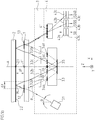
- the scanning beam path in the first exemplary embodiment will now be explained below, via which a plurality of phase-shifted distance signals S0, S120, S240 with respect to the distance zP or with respect to changes in the distance zP between the two plates 1, 2 are generated.
- the radiation beam emitted by a light source 3.1 in the scanning unit 3 strikes, at an angle ⁇ inclined relative to the optical axis A, on a beam splitter element 1.2 on the first plate 1.
- the light source 3.1 is preferably a laser emitting a linearly polarized beam.
- the beam splitter element 1.2 is formed in the present example as a planar beam splitter layer, which is arranged on that side of the first plate 1, which is oriented away from the light source 3.1; This page will be referred to below as the top of the first plate 1.
- the beam bundle incident from the light source 3.1 undergoes a division into two partial beams, one of which is reflected and another is transmitted.
- the reflected partial beam is subsequently referred to as a reference beam R
- the designation of the two split radiation beams as measurement and reference beams M, R is arbitrary and of course the designations could be chosen the other way around as well.
- the measuring beam M subsequently impinges on the first plate 1 nominally parallel second plate 2.
- a reflector element 2.2 is arranged on the first plate 1 facing side of the second plate 2, hereinafter also referred to as the underside of the second plate 2.
- the reflector element 2.2 is designed as a planar mirror layer whose reflective side is oriented in the direction of the first plate 1.
- the measuring beam M undergoes a first return reflection in the direction of the first plate 1.
- the measuring beam M then passes through the first plate 1 in a transparent, optically ineffective region, passes through a polarization-optical element 3.2b, formed as ⁇ / 8-plate, and then passes to a scanning 3.3 in the scanning unit 3.
- the measuring beam M passes through a first deflecting element, an associated retroreflector and a fourth deflecting element before it propagates again in the direction of the two plates 1, 2.
- the incident from the direction of the two plates 1, 2 forth measuring beam M first passes through a deflection AE, which is designed as a grid.
- the incident under the angle of incidence ⁇ in the optical axis A incident beam M is deflected by the deflection element AE such that it propagates after passing through desselbigen parallel to the optical axis A in the direction of a retroreflector RR.
- the retroreflector RR consists in the example shown from a diffractive lens DL and a reflector element R, formed as a mirror layer; Preferably, the diffractive lens DL and the reflector element R are arranged on the opposite sides of a plate-shaped, transparent support member.
- the diffractive lens DL the measuring beam M is focused on the reflector element R; from the reflector element R results in a back reflection in the direction of the diffractive lens DL, which collapses the emergent measuring beam M again, before it again meets the deflector AE.
- the deflecting element AE and / or the diffractive lens DL of the retroreflector RR can in principle also be designed in several parts, that is to say, for example. in each case only in the region of the incoming and outgoing measuring beam M.
- the deflection element AE deflects the measurement beam M, M 'differently during the first and second passes. That's how it turns out FIG. 3 the incident measuring beam M, M 'in +1. Distracted diffraction order, the failed measuring beam M but in -1. Diffraction order.
- the combined diffractive deflection lens element is arranged on one side of a plate-shaped, transparent carrier element, on the opposite side of the reflector element, wherein the reflective side is oriented towards the other side.
- a second combined, diffractive deflection lens element 3.4b is arranged on the side of the scanning plate 3.3, which faces the two plates 1, 2. This deflects the measuring beam M via the corresponding optical deflection function parallel to the optical axis A and focuses it simultaneously on its optical lens function on a reflector element 3.5 on the opposite side of the scanning 3.3. There, the measuring beam M impinges on the reflector element 3.5 in the region of the optical axis A, is reflected thereby and reaches a third combined, diffractive deflection lens element 3.4c.
- the third combined, diffractive deflection lens element 3.4c and its optical lens function results in a collimation of the measurement beam M, via the optical deflection function of the third combined diffractive deflection lens element 3.4c deflects the measurement beam M towards the optical axis A at an angle ⁇ .
- the measuring beam M propagating in the direction of the two plates 1, 2 first passes through another polarization-optical element 3.2c, again formed as ⁇ / 8 plate, then passes through a transparent region of the plate 1 and finally meets the reflector element 2.2 on the second There it then experiences a second return reflection, then passes through a further beam splitter element 1.3 on the first plate 1 and propagates in the direction of a detection unit 4th
- the reference beam R generated at the beam splitter element 1.2 of the first plate 1 is reflected back in the direction of the scanning unit 3 and passes there through a polarization-optical element 3.2a in the form of a ⁇ / 8 plate and reaches a first combined, diffractive deflection lens element 3.4a, which on the same side of the scanning 3.3 is arranged as the second, by the measuring beam M passed through combined diffractive deflection lens element 3.4b.
- the first combined diffractive deflection lens element 3.4a performs a basically comparable optical function as the second combined diffractive deflection lens element 3.4b on the measurement beam M.
- the optical deflection function of the first combined, diffractive Deflection lens element 3.4a the reference sub-beam R is aligned parallel to the optical axis A, while it is focused on the optical lens function on the reflector element 3.5 in the region of the optical axis A on the reflector element 3.6, which is arranged on the side of the scanning 3.3, the the two plates 1, 2 faces.
- the reference beam R then passes via a further reflection on the reflector element 3.5 to the fourth combined, diffractive deflection lens element 3.4d. This collimates the reference beam R again and also deflects it at an angle ⁇ to the optical axis A down.
- the reference beam R thus passes through a first deflection element, an associated retroreflector and a fourth deflection element before it propagates again in the direction of the two plates 1, 2.
- a polarization-optical element 3.2d designed as ⁇ / 8 the reference beam R then passes onto the beam splitter element 1.3 on the first plate 1, where it is superimposed with the measuring beam M also arriving there and propagates in the direction of the detection unit 4 after further reflection ,
- the reference beam R in the present embodiment in the scanning 3.3 traversed due to the additional reflection on the reflector element 3.6 is preferably chosen so that it is equal to the additional optical path of the measuring beam M between the in the nominal position of the plates 1, 2 Plates 1, 2 is.
- the optical path lengths of the two beams are thus compensated in the nominal position. This results in a particularly low position noise, since the phase noise of the light source 3.1 in this nominal position has no influence.
- a short coherence length light source 3.1 can be used, which substantially reduces interference from unwanted noise (e.g., by "speckle" on housing walls).
- the measurement and reference beams M, R are circularly polarized relative to each other by suitably oriented polarization-optical components 3.2a-3.2d, each formed as ⁇ / 8 platelets.
- a splitting grating 4.1 in the detection unit 4 splits the two collinear measuring and reference beams M, R into three further ones Partial beam on. These pass through respective polarizers 4.2a, 4.2b, 4.2c before they are converted by optoelectronic detector elements 4.3a, 4.3b, 4.3c into phase-shifted, electrical distance signals S0, S120, S240.
- the polarizers 4.2a, 4.2b, 4.2c are oriented at an angle of 60 ° to one another, so that a phase shift of 120 ° in each case results between the generated distance signals S0, S120, S240.
- all the radiation beams from the light source 3.1 to the detection unit 4 extend in one plane, namely in the one in FIG Fig. 1a displayed XZ plane.
- the effective measuring point for each of the two plates 1, 2 lies on the optical axis A between the points of impact of the corresponding partial beams M, R.
- the effective measuring point for the second plate is located at location 2.1 on the underside of the plate 2; for the first plate 1, the effective measuring point is located at the location 1.1 on the upper side of the plate 1.
- the measuring points 1.1, 2.1 remain even with a z-displacement of the first plate 1 on the optical axis A lying.
- an additional optical position measuring device which in the FIGS. 1a . 1b is not shown, can - as already mentioned above - also a lateral displacement of the two plates 1, 2 are detected in the xy plane to each other.
- Both plates 1, 2 can for this purpose have at the measuring points 1.1, 2.1 grating structures which are scanned by a suitable scanning head.
- the scanning of a scanning optics such as from the DE 10 2010 043 263 is known, is arranged in the scanning unit 3 preferably in the vicinity of the optical axis A and also has effective measuring points at the locations 1.1, 2.1. on.
- Common measuring points 1.1, 2.1 of the inventive device for interferometric distance determination and an additional optical position measuring device allow a particularly favorable evaluation of the distance signals generated with a simple determination of several degrees of freedom.
- the 6D pose can be used to calculate the relative position of the plates 1, 2 or associated machine parts at the location of a Tool Center Point (TCP), thus correcting any abbe errors.
- TCP Tool Center Point
- the first plate 1 is provided on the upper side outside the areas with the beam splitter elements 1.2, 1.3 and on the entire bottom with an antireflection layer. Also advantageous is the arrangement of a diaphragm (not shown in the figures) in front of the detection unit 4 or in the area in which the collinearly superimposed measuring and reference beams M, R propagate in the direction of the detection unit 4, in order to suppress disturbing reflections. It is also favorable to make the first plate 1 slightly wedge-shaped in order to avoid interference with multiple reflections within this plate 1.
- FIGS. 4a . 4b . 5 and 6a and 6b show the beam path or parts thereof in different views analogously to the first embodiment in schematic form
- FIG. 5 a plan view of the top of the scanning
- FIG. 6a and 6b Views of the first and second plate of the device according to the invention.
- the second exemplary embodiment of a device according to the invention differs from the first embodiment primarily in that the beam path from the light source 13.1 to the detection unit 14 no longer extends completely in one plane, as was the case in the xz plane in the first example.
- the light source 13.1 is arranged in this embodiment in the y-direction offset from the optical axis A and emits a beam at the inclination angle ⁇ to the optical axis A parallel to the xz-plane.
- the reference beam R and the measuring beam M hit in the y-direction offset to the associated first and second combined diffractive deflection lens elements 13.4a, 13.4b on the top of the scanning 13.3 in the scanning unit 13.
- Their lens functions are chosen in this embodiment so that both the reference beam R and the measuring beam M are focused on the reflector element 13.5 on the underside of the scanning 13.3, seen laterally, the focus location is again on the optical axis A. Symmetrical to the optical axis A.
- FIGS. 4a . 4b and FIGS. 6a, 6b show components of such an optical position-measuring device in a highly schematic manner.
- These include a scanning unit 20 assigned to the scanning unit 13 and a first measuring graduation 21 on the first plate 11 and a second measuring graduation 22 on the second plate 12.
- the first measuring graduation 21 is in this case arranged centrally between the two beam splitter elements 11.2, 11.3 of the first plate 11, the second measuring standard 22 in the middle between the two reflector elements 12.2, 12.3 of the second plate 12.
- the scanning head 20 may comprise approximately a light source and a detector unit; as the first and second measuring graduation 21, 22, an incremental graduation extending in the x-direction is provided in each case.
- baffles may serve as grating, prisms or mirrors
- the lenses may be made diffractive or refractive.
- the retroreflector functionality via triple mirrors or triple prisms, i. the diffractive or refractive lens, the associated mirror and the subsequent diffractive or refractive lens could also be replaced by a triple prism or a triple mirror.
- the coherence length of the light source is chosen to be so short that disruptive multiple reflections on the two plates are no longer capable of interfering.
- phase-shifted distance signals starting from mutually orthogonally polarized beam bundles can be carried out in an alternative manner as described in the two embodiments.
- the tilt of the two interfering beams could also be achieved by slightly varying the deflection angles of the combined diffractive deflection lens elements for the measuring and reference beams.
Description
Die vorliegende Erfindung betrifft eine Vorrichtung zur interferometrischen Abstandsbestimmung zwischen zwei weitgehend parallel angeordneten Platten.The present invention relates to an apparatus for interferometric distance determination between two plates arranged largely in parallel.
Neben der Erfassung von Positionsänderungen zweier zueinander beweglicher Objekte in einer lateralen Richtung gibt es Messaufgaben, bei denen ausschließlich oder ggf. zusätzlich noch die Bestimmung des Abstands dieser Objekte in einer hierzu senkrechten, vertikalen Richtung erforderlich ist. Beispielsweise kann es sich hierbei um die Bestimmung des Abstands zwischen zwei weitgehend parallel zueinander angeordneten Platten handeln, wobei diese Platten lediglich einen geringen Abstand zueinander aufweisen. Für eine hochgenaue Abstandsmessung bieten sich hierbei interferometrische Verfahren an, wie sie etwa in der
Die aus der
Die aus der
Aus der
Die
Der vorliegenden Erfindung liegt das Problem zugrunde, eine Vorrichtung zur hochgenauen interferometrischen Abstandsbestimmung zwischen zwei weitgehend parallel angeordneten Platten schaffen, die möglichst große Anbau- und Betriebstoleranzen aufweist, also insbesondere unempfindlich gegenüber eventuellen Verkippungen der beiden Platten ist.The
The present invention is based on the problem to provide a device for high-precision interferometric distance determination between two largely parallel plates, which has the largest possible mounting and operating tolerances, that is in particular insensitive to any tilting of the two plates.
Diese Aufgabe wird erfindungsgemäß durch eine Vorrichtung mit den Merkmalen des Anspruchs 1 gelöst.
Vorteilhafte Ausführungen der erfindungsgemäßen Vorrichtung ergeben sich aus den Maßnahmen in den abhängigen Ansprüchen.This object is achieved by a device having the features of claim 1.
Advantageous embodiments of the device according to the invention will become apparent from the measures in the dependent claims.
Die erfindungsgemäße Vorrichtung zur interferometrischen Abstandsbestimmung zwischen zwei weitgehend parallel angeordneten Platten umfasst eine Lichtquelle, mindestens ein Strahlteilerelement, mindestens ein Reflektorelement, mehrere Ablenkelemente, mehrere Retroreflektoren und einer Detektionseinheit. Hierbei trifft ein von der Lichtquelle emittiertes Strahlenbündel geneigt auf ein Strahlteilerelement auf der ersten Platte auf und erfährt dort eine Aufteilung in ein reflektiertes Referenzstrahlenbündel und ein transmittiertes Messstrahlenbündel. Das Messstrahlenbündel trifft auf ein Reflektorelement auf der zweiten Platte auf und erfährt dort eine erste Rückreflexion in Richtung der ersten Platte. Das Referenzstrahlenbündel durchläuft ein erstes Ablenkelement, das Messstrahlenbündel ein zweites Ablenkelement; anschließend durchlaufen das Referenz- und Messstrahlenbündel jeweils einen zugeordneten Retroreflektor; dann durchläuft das Messstrahlenbündel ein drittes Ablenkelement und das Referenzstrahlenbündel ein viertes Ablenkelement durchläuft, wobei sowohl das erste und zweite Ablenkelement als auch das dritte und vierte Ablenkelement jeweils unterschiedliche Ablenkwirkungen auf die durchlaufenden Referenz- und Messstrahlenbündel ausüben. Das Referenzstrahlenbündel erfährt dann eine Reflexion an der ersten Platte und das Messstrahlenbündel dann eine zweite Rückreflexion an einem Reflektorelement der zweiten Platte, so dass das Messstrahlenbündel und das Referenzstrahlenbündel dann kollinear in Richtung der Detektionseinheit propagieren, wo aus den interferierenden Mess- und Referenzstrahlenbündeln mehrere phasenverschobene Abstandssignale erzeugbar sind.
In einer möglichen Ausführungsform umfassen die Retroreflektoren eine erste diffraktive Linse, ein Reflektorelement und eine zweite diffraktive Linse, wobei über die erste diffraktive Linse eine Fokussierung des darauf einfallenden Mess- oder Referenzstrahlenbündels auf das Reflektorelement und über die zweite diffraktive Linse eine Kollimation des vom Reflektorelement reflektierten, ausfallenden Mess- oder Referenzstrahlenbündels erfolgt.The inventive apparatus for interferometric distance determination between two largely parallel plates comprises a light source, at least one beam splitter element, at least one reflector element, a plurality of deflection elements, a plurality of retroreflectors and a detection unit. In this case, a radiation beam emitted by the light source impinges on a beam splitter element on the first plate and experiences there a division into a reflected reference beam and a transmitted measuring beam. The measuring beam impinges on a reflector element on the second plate and experiences there a first return reflection in the direction of the first plate. The reference beam passes through a first deflecting element, the measuring beam passes through a second deflecting element; Subsequently, the reference and measuring beams each pass through an associated retroreflector; The measuring beam then passes through a third deflection element and the reference beam passes through a fourth deflection element, wherein both the first and second deflection elements and the third and fourth deflection elements each exert different deflection effects on the passing reference and measurement beams. The reference beam then experiences a reflection on the first plate and the measuring beam then a second return reflection on a reflector element of the second plate, so that the measuring beam and the reference beam then propagate collinearly in the direction of the detection unit, where from the interfering measuring and reference beams more phase-shifted distance signals can be generated.
In one possible embodiment, the retroreflectors comprise a first diffractive lens, a reflector element and a second diffractive lens, wherein focusing of the measuring or reference beam beam impinging thereon onto the reflector element takes place via the first diffractive lens and collimation of the precipitated measuring or reference beam bundle reflected by the reflector element takes place via the second diffractive lens.
Es ist hierbei möglich, dass die erste und zweite diffraktive Linse auf einer ersten Seite eines plattenförmigen, transparenten Trägerelements angeordnet sind und auf der gegenüberliegenden, zweiten Seite des Trägerelements das Reflektorelement angeordnet ist, dessen reflektierende Seite in Richtung der ersten Seite orientiert ist.It is possible in this case for the first and second diffractive lenses to be arranged on a first side of a plate-shaped, transparent carrier element and for the reflector element to be arranged on the opposite, second side of the carrier element, whose reflective side is oriented in the direction of the first side.
Desweiteren kann vorgesehen werden, dass
- das erste Ablenkelement und die erste diffraktive Linse und das vierte Ablenkelement und die zweite diffraktive Linse eines ersten Retroreflektors als erstes und viertes kombiniertes diffraktives Ablenk-Linsenelement ausgebildet sind und
- das zweite Ablenkelement und die erste diffraktive Linse und das dritte Ablenkelement und die zweite diffraktive Linse eines zweiten Retroreflektors als zweites und drittes kombiniertes diffraktives Ablenk-Linsenelement ausgebildet sind.
- the first deflection element and the first diffractive lens and the fourth deflection element and the second diffractive lens of a first retroreflector are formed as first and fourth combined diffractive deflection lens element and
- the second deflection element and the first diffractive lens and the third deflection element and the second diffractive lens of a second retroreflector are formed as second and third combined diffractive deflection lens element.
Gemäß einem weiteren Aspekt der vorliegenden Erfindung ist es möglich, dass die kombinierten diffraktiven Ablenk-Linsenelemente auf einer ersten Seite eines plattenförmigen, transparenten Trägerelements angeordnet sind und auf der gegenüberliegenden zweiten Seite des Trägerelements das Reflektorelement angeordnet ist, dessen reflektierende Seite in Richtung der ersten Seite orientiert ist.According to a further aspect of the present invention, it is possible for the combined diffractive deflection lens elements to be arranged on a first side of a plate-shaped, transparent carrier element and for the reflector element to be arranged on the opposite second side of the carrier element, whose reflective side is in the direction of the first side is oriented.
In einer vorteilhaften Ausführungsform der erfindungsgemäßen Vorrichtung sind die optischen Weglängen des Mess- und Referenzstrahlenbündels in einer definierten Nennlage identisch.In an advantageous embodiment of the device according to the invention, the optical path lengths of the measuring and reference beams are identical in a defined nominal position.
Um dies zu erreichen, kann vorgesehen werden, dass zur Einstellung identischer optischer Weglängen die dem Mess- und Referenzstrahlenbündel jeweils zugeordneten Retroreflektoren unterschiedlich ausgebildet sind.In order to achieve this, provision can be made for the setting of identical optical path lengths to have the retroreflectors respectively assigned to the measuring and reference beams differently.
Mit Vorteil gilt für den Winkel, unter dem das von der Lichtquelle emittierte Strahlenbündel geneigt auf die erste Platte einfällt: ![]()
- Θ := Winkel gegen eine Senkrechte auf die erste Platte, unter dem das von der Lichtquelle emittierte Strahlenbündel auf die erste Platte einfällt
- rS := Strahlradius der Lichtquelle
- zP := Abstand der ersten und zweiten Platte
- Θ: = angle against a perpendicular to the first plate, under which the radiation beam emitted by the light source is incident on the first plate
- rS: = beam radius of the light source
- zP: = distance of the first and second plate
In einer möglichen Variante der erfindungsgemäßen Vorrichtung kann vorgesehen sein, dass die erste Platte als transparente Planplatte ausgebildet ist,
- auf dessen der Lichtquelle abgewandten Seite in einem räumlich begrenzten ersten Bereich als Strahlteilerelement eine planare Strahlteilerschicht angeordnet ist, auf den das von der Lichtquelle emittierte Strahlenbündel auftrifft und
- auf der gleichen Seite in einem räumlich begrenzten zweiten Bereich als weiteres Strahlteilerelement eine weitere planare Strahlteilerschicht angeordnet ist, auf den das Messstrahlenbündel nach der zweiten Rückreflexion am Reflektorelement der zweiten Platte auftrifft und auf den das Referenzstrahlenbündel nach dem Durchlaufen des vierten Ablenkelements auftrifft.
- on the side facing away from the light source, a planar beam splitter layer is arranged as a beam splitter element in a spatially limited first region, on which the radiation beam emitted by the light source strikes and
- a further planar beam splitter layer is arranged on the same side in a spatially limited second region as a further beam splitter element, onto which the measuring beam strikes after the second return reflection at the reflector element of the second plate and on which the reference beam strikes after passing through the fourth deflecting element.
Ferner ist es möglich, dass die erste Platte auf der der Lichtquelle zugewandten Seite sowie auf der entgegengesetzten Seite außerhalb der Bereiche mit den Strahlteilerelementen eine Antireflexionsschicht aufweist und/oder eine Blende in dem Bereich aufweist, in dem die kollinear überlagerten Mess- und Referenzstrahlenbündel in Richtung der Detektionseinheit propagieren.Furthermore, it is possible for the first plate to have an antireflection coating on the side facing the light source and on the opposite side outside the regions with the beam splitter elements and / or a diaphragm in the region in which the collinear superimpose superimposed measuring and reference beams in the direction of the detection unit.
Darüberhinaus kann die zweite Platte als transparente Planplatte ausgebildet werden, auf dessen der Lichtquelle zugewandten Seite als Reflektorelemente planare Spiegelschichten angeordnet ist, deren reflektierende Seiten in Richtung der ersten Platte orientiert ist.In addition, the second plate can be formed as a transparent plane plate, on whose side facing the light source as reflector elements planar mirror layers is arranged, whose reflective sides is oriented in the direction of the first plate.
Es ist ferner möglich, ein System aufzubauen, bestehend aus einer erfindungsgemäßen Vorrichtung kombiniert mit einer optischen Positionsmesseinrichtung, die geeignet ist, eine Relativverschiebung der ersten und zweiten Platte parallel zu den Anordnungsebenen der beiden Platten zu erfassen.It is also possible to construct a system consisting of a device according to the invention combined with an optical position-measuring device which is suitable for detecting a relative displacement of the first and second plates parallel to the arrangement planes of the two plates.
Vorzugsweise fallen hierbei die Messpunkte der optischen Positionsmesseinrichtung und der Vorrichtung zur interferometrischen Abstandsbestimmung zusammen.In this case, the measuring points of the optical position-measuring device and the device for interferometric distance determination preferably coincide.
Als entscheidender Vorteil der erfindungsgemäßen Lösung ist deren große Unempfindlichkeit gegenüber eventuellen Verkippungen der beiden Platten zu erwähnen; daraus wiederum resultieren die gewünschten großen Anbau- und Betriebstoleranzen. Maßgeblich dafür verantwortlich ist das erfindungsgemäße Vorsehen einer Retroreflexion, worüber mindestens eines der zur Interferenz gelangenden Strahlenbündel ein zweites Mal von einer der beiden Platten reflektiert wird. Über die hierbei resultierende zweite Reflexion, etwa des Messstrahlenbündels, an einer Platte wird eine eventuelle Verkippung dieser Platte gegenüber der erforderlichen Parallelausrichtung optisch kompensiert und verursacht so keine Messfehler mehr.The decisive advantage of the solution according to the invention is their great insensitivity to possible tilting of the two plates to mention; this in turn results in the desired large mounting and operating tolerances. Decisively responsible for this is the provision according to the invention of a retroreflection, by means of which at least one of the radiation beams reaching the interference is reflected a second time by one of the two plates. By means of the resulting second reflection, for example of the measuring beam, on a plate, a possible tilting of this plate relative to the required parallel alignment is optically compensated and thus no longer causes measurement errors.
Die erfindungsgemäße Vorrichtung erlaubt ferner die Nutzung von Mess- und Referenzstrahlenbündeln mit ausgedehnten Strahlquerschnitten. Die interferometrische Abstandsbestimmung wird auf diese Art und Weise unempfindlich gegenüber möglichen lokalen Defekten auf den beiden Platten, da ein Strahlenbündel mit großem Strahlquerschnitt die mittleren Oberflächeneigenschaften über eine entsprechend größere Fläche erfasst.The device according to the invention also allows the use of measuring and reference beams with extended beam cross sections. The interferometric distance determination in this way is insensitive to possible local defects on the two Plates, as a beam with a large beam cross-section detects the average surface properties over a correspondingly larger area.
Die Mess- und Referenzstrahlenbündel fallen in der erfindungsgemäßen Vorrichtung stets geneigt auf die beiden Platten ein, deren Abstand zu bestimmen ist. Darüber ist sichergestellt, dass die mehrfach zwischen den beiden Platten hin und her reflektierten Strahlenbündel, die nicht zur Signalgewinnung beitragen, seitlich so stark abgelenkt werden, dass diese nicht mehr auf die Detektionseinheit treffen können. Die Signalqualität und Messgenauigkeit wird auf diese Art und Weise nochmals erhöht.In the device according to the invention, the measurement and reference beams always fall inclinedly onto the two plates whose distance is to be determined. In addition, it is ensured that the beam bundles reflected back and forth several times between the two plates, which do not contribute to signal extraction, are laterally deflected so much that they can no longer impact on the detection unit. The signal quality and measuring accuracy are increased again in this way.
Auf Seiten der beiden Platten sind in der erfindungsgemäßen Vorrichtung lediglich homogene, planare Beschichtungen auf den beiden Platten als optisch funktionsrelevante Komponenten vorgesehen, d.h. insbesondere keine Gitterstrukturen. Im Fall einer lateralen Verschiebung der beiden Platten zueinander bleiben die resultierenden Abstandssignale daher weitestgehend konstant. Eine elektronische Signalkorrektur zur Minimierung eventueller Interpolationsfehler im Fall einer Lateralverschiebung der Platten gegeneinander ist daher für die Abstandssignale nicht erforderlich.On the side of the two plates in the device according to the invention only homogeneous, planar coatings on the two plates are provided as optically function-relevant components, i. in particular no lattice structures. In the case of a lateral displacement of the two plates to each other, the resulting distance signals therefore remain largely constant. An electronic signal correction to minimize any interpolation error in the case of a lateral displacement of the plates against each other is therefore not required for the distance signals.
Die erfindungsgemäße Vorrichtung lässt sich darüberhinaus besonders vorteilhaft mit einer optischen Positionsmesseinrichtung zur Erfassung der Relativverschiebung der beiden Platten in lateraler Richtung zu einem Gesamt-System kombinieren.In addition, the device according to the invention can be combined particularly advantageously with an optical position-measuring device for detecting the relative displacement of the two plates in the lateral direction to form an overall system.
Weitere Einzelheiten und Vorteile der vorliegenden Erfindung seien anhand der nachfolgenden Beschreibung von Ausführungsbeispielen der erfindungsgemäßen Vorrichtung in Verbindung mit den Figuren erläutert.Further details and advantages of the present invention will be explained with reference to the following description of embodiments of the device according to the invention in conjunction with the figures.
Es zeigt
- Figur 1a
- eine schematisierte Darstellung des Strahlengangs eines ersten Ausführungsbeispiels der erfindungsgemäßen Vorrichtung in einer ersten Ansicht;
- Figur 1b
- einen Teil des Strahlengangs des ersten Ausführungsbeispiels in einer zweiten Ansicht;
- Figur 2
- eine Draufsicht auf die Oberseite der Abtastplatte aus dem ersten Ausführungsbeispiel;
- Figur 3
- eine schematisierte Darstellung einer Komponente der erfindungsgemäßen Vorrichtung;
- Figur 4a
- eine schematisierte Darstellung des Strahlengangs eines zweiten Ausführungsbeispiels der erfindungsgemäßen Vorrichtung in einer ersten Ansicht;
- Figur 4b
- einen Teil des Strahlengangs des zweiten Ausführungsbeispiels in einer zweiten Ansicht;
- Figur 5
- eine Draufsicht auf die Oberseite der Abtastplatte aus dem zweiten Ausführungsbeispiel;
- Figur 6a
- eine Draufsicht auf die Oberseite der ersten Platte aus dem zweiten Ausführungsbeispiel;
- Figur 6b
- eine Draufsicht auf die Unterseite der zweiten Platte aus dem zweiten Ausführungsbeispiel.
- FIG. 1a
- a schematic representation of the beam path of a first embodiment of the device according to the invention in a first view;
- FIG. 1b
- a part of the beam path of the first embodiment in a second view;
- FIG. 2
- a plan view of the top of the scanning of the first embodiment;
- FIG. 3
- a schematic representation of a component of the device according to the invention;
- FIG. 4a
- a schematic representation of the beam path of a second embodiment of the device according to the invention in a first view;
- FIG. 4b
- a part of the beam path of the second embodiment in a second view;
- FIG. 5
- a plan view of the top of the scanning of the second embodiment;
- FIG. 6a
- a plan view of the top of the first plate of the second embodiment;
- FIG. 6b
- a plan view of the underside of the second plate of the second embodiment.
Mit Hilfe der erfindungsgemäßen Vorrichtung ist die interferometrische Bestimmung des Abstands zP zwischen zwei weitgehend parallel angeordneten Platten 1, 2 mit hoher Genauigkeit möglich. Bei den beiden Platten 1, 2 handelt es sich etwa um zwei Planplatten aus Glas, die beispielsweise in einer optischen Positionsmesseinrichtung angeordnet und in der lateralen xy-Ebene in ein oder zwei Richtungen relativ zueinander beweglich sind. Das System, bestehend aus der optischen Positionsmesseinrichtung und der erfindungsgemäßen Vorrichtung zur interferometrischen Abstandsbestimmung, ist in einer Maschine angeordnet, und dient zur Erzeugung von hochgenauen Positionsinformationen für eine Maschinensteuerung bzgl. relativ zueinander beweglicher Maschinenkomponenten, die mit den beiden Platten 1, 2 verbunden sind. Über die optische Positionsmesseinrichtung ist die Positionserfassung in der xy-Ebene möglich. Hierzu sind auf den beiden Platten 1, 2 im Bereich der Orte 1.1, 2.1 - in den Figuren nicht dargestellte - Maßverkörperungen in Form von Gitterstrukturen angeordnet, um über eine optische Abtastung derselbigen Positionsinformationen bzgl. der Verschiebung der Platten 1, 2 zueinander in der lateralen xy-Ebene zu erzeugen; neben der Maßverkörperung umfasst die entsprechende optische Positionsmesseinrichtung noch einen - ebenfalls nicht dargestellten - Abtastkopf, der z.B. in der Abtasteinheit 3 der erfindungsgemäßen Vorrichtung angeordnet ist. Geeignete Abtastoptiken bzw. geeignete optische Positionsmesseinrichtungen sind etwa aus der
Im dargestellten ersten Ausführungsbeispiel der erfindungsgemäßen Vorrichtung zur interferometrischen Abstandsbestimmung sind die verschiedenen Komponenten der Vorrichtung in einer Abtasteinheit 3 angeordnet, die in z-Richtung beabstandet von den beiden Platten 1, 2 platziert ist.In the illustrated first embodiment of the device according to the invention for interferometric distance determination, the various components of the device are arranged in a scanning unit 3, which is placed in the z-direction at a distance from the two plates 1, 2.
Selbstverständlich ist die Anordnung aller Komponenten in einer einzigen, gemeinsamen Abtasteinheit nicht zwingend erforderlich; denkbar wäre etwa auch, z.B. die Lichtquelle 3.1 und/oder die Detektionseinheit 4 bzw. Teile davon räumlich getrennt von der Abtasteinheit 3 anzuordnen und mittels lichtleitender Fasern mit der Abtasteinheit 3 zu verbinden.Of course, the arrangement of all components in a single, common scanning unit is not mandatory; for example, it would also be conceivable, e.g. to arrange the light source 3.1 and / or the
Zur Erläuterung des Funktionsprinzips der erfindungsgemäßen Vorrichtung wird nunmehr nachfolgend der Abtaststrahlengang im ersten Ausführungsbeispiel erläutert, über den mehrere phasenverschobene Abstandssignale S0, S120, S240 bzgl. des Abstands zP bzw. bzgl. Änderungen des Abstands zP zwischen den beiden Platten 1, 2 erzeugt werden.In order to explain the principle of operation of the device according to the invention, the scanning beam path in the first exemplary embodiment will now be explained below, via which a plurality of phase-shifted distance signals S0, S120, S240 with respect to the distance zP or with respect to changes in the distance zP between the two plates 1, 2 are generated.
Das von einer Lichtquelle 3.1 in der Abtasteinheit 3 emittierte Strahlenbündel trifft, um einen Winkel Θ geneigt gegenüber der optischen Achse A, auf ein Strahlteilerelement 1.2 auf der ersten Platte 1. Als Lichtquelle 3.1 dient vorzugsweise ein Laser, der ein linear polarisiertes Strahlenbündel emittiert. Das Strahlteilerelement 1.2 ist im vorliegenden Beispiel als planare Strahlteilerschicht ausgebildet, die auf derjenigen Seite der ersten Platte 1 angeordnet ist, die abgewandt zur Lichtquelle 3.1 orientiert ist; diese Seite sei im folgenden auch als Oberseite der ersten Platte 1 bezeichnet. Über das Strahlteilerelement 1.2 erfährt das von der Lichtquelle 3.1 her einfallende Strahlenbündel eine Aufteilung in zwei Teilstrahlenbündel, von denen eines reflektiert und ein anderes transmittiert wird. Das reflektierte Teilstrahlenbündel wird nachfolgend als Referenzstrahlenbündel R bezeichnet, das transmittierte Strahlenbündel als Messstrahlenbündel M. Es sei darauf hingewiesen, dass die Bezeichnung der beiden aufgespaltenen Strahlenbündel als Mess- und Referenzstrahlenbündel M, R willkürlich ist und selbstverständlich die Bezeichnungen auch anders herum gewählt werden könnten.The radiation beam emitted by a light source 3.1 in the scanning unit 3 strikes, at an angle Θ inclined relative to the optical axis A, on a beam splitter element 1.2 on the first plate 1. As the light source 3.1 is preferably a laser emitting a linearly polarized beam. The beam splitter element 1.2 is formed in the present example as a planar beam splitter layer, which is arranged on that side of the first plate 1, which is oriented away from the light source 3.1; This page will be referred to below as the top of the first plate 1. Via the beam splitter element 1.2, the beam bundle incident from the light source 3.1 undergoes a division into two partial beams, one of which is reflected and another is transmitted. The reflected partial beam is subsequently referred to as a reference beam R It should be noted that the designation of the two split radiation beams as measurement and reference beams M, R is arbitrary and of course the designations could be chosen the other way around as well.
Das Messstrahlenbündel M trifft nachfolgend auf die zur ersten Platte 1 nominal parallele zweite Platte 2. Auf der der ersten Platte 1 zugewandten Seite der zweiten Platte 2, nachfolgend auch als Unterseite der zweiten Platte 2 bezeichnet, ist ein Reflektorelement 2.2 angeordnet. Das Reflektorelement 2.2 ist als planare Spiegelschicht ausgebildet, deren reflektierende Seite in Richtung der ersten Platte 1 orientiert ist. Am Reflektorelement 2.2 erfährt das Messstrahlenbündel M eine erste Rückreflexion in Richtung der ersten Platte 1. Das Messstrahlenbündel M durchtritt dann die erste Platte 1 in einem transparenten, optisch unwirksamen Bereich, durchläuft ein polarisationsoptisches Element 3.2b, ausgebildet als λ/8-Plättchen, und gelangt dann auf eine Abtastplatte 3.3 in der Abtasteinheit 3. In der Abtastplatte 3.3 sind über die darauf angeordneten optischen Elemente verschiedene optische Funktionen implementiert, die auf das Messstrahlenbündel M beim Durchlaufen der Abtastplatte 3.3 bestimmte optische Wirkungen ausüben. So durchläuft das Messstrahlenbündel M hierbei ein erstes Ablenkelement, einen zugeordneten Retroreflektor sowie ein viertes Ablenkelement, bevor es wieder in Richtung der beiden Platten 1, 2 propagiert.The measuring beam M subsequently impinges on the first plate 1 nominally parallel second plate 2. On the first plate 1 facing side of the second plate 2, hereinafter also referred to as the underside of the second plate 2, a reflector element 2.2 is arranged. The reflector element 2.2 is designed as a planar mirror layer whose reflective side is oriented in the direction of the first plate 1. At the reflector element 2.2 the measuring beam M undergoes a first return reflection in the direction of the first plate 1. The measuring beam M then passes through the first plate 1 in a transparent, optically ineffective region, passes through a polarization-optical element 3.2b, formed as λ / 8-plate, and then passes to a scanning 3.3 in the scanning unit 3. In the scanning 3.3 are implemented on the optical elements arranged thereon various optical functions that exert on the measuring beam M when passing through the scanning 3.3 certain optical effects. Thus, the measuring beam M passes through a first deflecting element, an associated retroreflector and a fourth deflecting element before it propagates again in the direction of the two plates 1, 2.
Zur näheren Erläuterung der verschiedenen optischen Wirkungen auf das Messstrahlenbündel M beim Durchlaufen der Abtastplatte 3.3 sei auf die
Es sei an dieser Stelle darauf hingewiesen, dass etwa das Ablenkelement AE und/oder auch die diffraktive Linse DL des Retroreflektors RR grundsätzlich auch mehrteilig ausgebildet werden können, also z.B. jeweils nur im Bereich des ein- und ausfallenden Messstrahlenbündels M.It should be noted at this point that, for example, the deflecting element AE and / or the diffractive lens DL of the retroreflector RR can in principle also be designed in several parts, that is to say, for example. in each case only in the region of the incoming and outgoing measuring beam M.
Bei einer kleinen Änderung des Einfallwinkels Θ'in des Messstrahlenbündels M' - etwa aufgrund einer Verkippung der beiden Platten 1, 2 - hin zu einem etwas flacheren Einfallswinkel Θ'in wird der Ausfallswinkel Θ'out des Messstrahlenbündels M' nach dem Ablenkelement AE etwas steiler. Die in
Zu beachten ist dabei ferner, dass das Ablenkelement AE beim ersten und zweiten Durchgang das Messstrahlenbündel M, M' unterschiedlich ablenkt. So wird wie aus
Alternativ zur dargestellten Anordnung in
Im ersten Ausführungsbeispiel der erfindungsgemäßen Vorrichtung ist demzufolge auf der Seite der Abtastplatte 3.3, die den beiden Platten 1, 2 zugewandt ist, ein zweites kombiniertes, diffraktives Ablenk-Linsenelement 3.4b angeordnet. Dieses lenkt das Messstrahlenbündel M über die entsprechende optische Ablenkfunktion parallel zur optischen Achse A ab und fokussiert es gleichzeitig über seine optische Linsenfunktion auf ein Reflektorelement 3.5 auf der gegenüberliegenden Seite der Abtastplatte 3.3. Dort trifft das Messstrahlenbündel M im Bereich der optischen Achse A auf das Reflektorelement 3.5, wird hiervon reflektiert und gelangt auf ein drittes kombiniertes, diffraktives Ablenk-Linsenelement 3.4c. Über das dritte kombinierte, diffraktive Ablenk-Linsenelement 3.4c und dessen optischer Linsenfunktion resultiert eine Kollimation des Messstrahlenbündels M, über die optische Ablenkfunktion des dritten kombinierten, diffraktiven Ablenk-Linsenelements 3.4c eine Ablenkung des Messstrahlenbündels M hin zur optischen Achse A unter dem Winkel Θ. Anschließend durchtritt das in Richtung der beiden Platten 1, 2 propagierende Messstrahlenbündel M zunächst ein weiteres polarisationsoptisches Element 3.2c, wiederum ausgebildet als λ/8-Plättchen, durchläuft dann einen transparenten Bereich der Platte 1 und trifft schließlich wieder auf das Reflektorelement 2.2 auf der zweiten Platte 2. Dort erfährt es dann eine zweite Rückreflexion, durchtritt sodann ein weiteres Strahlteilerelement 1.3 auf der ersten Platte 1 und propagiert in Richtung einer Detektionseinheit 4.Accordingly, in the first exemplary embodiment of the device according to the invention, a second combined, diffractive deflection lens element 3.4b is arranged on the side of the scanning plate 3.3, which faces the two plates 1, 2. This deflects the measuring beam M via the corresponding optical deflection function parallel to the optical axis A and focuses it simultaneously on its optical lens function on a reflector element 3.5 on the opposite side of the scanning 3.3. There, the measuring beam M impinges on the reflector element 3.5 in the region of the optical axis A, is reflected thereby and reaches a third combined, diffractive deflection lens element 3.4c. The third combined, diffractive deflection lens element 3.4c and its optical lens function results in a collimation of the measurement beam M, via the optical deflection function of the third combined diffractive deflection lens element 3.4c deflects the measurement beam M towards the optical axis A at an angle Θ. Subsequently, the measuring beam M propagating in the direction of the two plates 1, 2 first passes through another polarization-optical element 3.2c, again formed as λ / 8 plate, then passes through a transparent region of the plate 1 and finally meets the reflector element 2.2 on the second There it then experiences a second return reflection, then passes through a further beam splitter element 1.3 on the first plate 1 and propagates in the direction of a detection unit 4th
Das am Strahlteilerelement 1.2 der ersten Platte 1 erzeugte Referenzstrahlenbündel R wird in Richtung der Abtasteinheit 3 zurückreflektiert und durchläuft dort ein polarisationsoptisches Element 3.2a in Form eines λ/8-Plättchens und gelangt auf ein erstes kombiniertes, diffraktives Ablenk-Linsenelement 3.4a, welches auf der gleichen Seite der Abtastplatte 3.3 angeordnet ist, wie das zweite, vom Messstrahlenbündel M durchlaufene kombinierte, diffraktive Ablenk-Linsenelement 3.4b. Auf das Referenzstrahlenbündel R übt das erste kombinierte, diffraktive Ablenk-Linsenelement 3.4a eine grundsätzlich vergleichbare optische Funktion aus wie das zweite kombinierte, diffraktive Ablenk-Linsenelement 3.4b auf das Messstrahlenbündel M. Das bedeutet, dass über die optische Ablenkfunktion des ersten kombinierten, diffraktiven Ablenk-Linsenelements 3.4a das Referenzteilstrahlenbündel R parallel zur optischen Achse A ausgerichtet wird, während es über dessen optische Linsenfunktion über das Reflektorelement 3.5 im Bereich der optischen Achse A auf das Reflektorelement 3.6 fokussiert wird, das auf der Seite der Abtastplatte 3.3 angeordnet ist, die den beiden Platten 1, 2 zugewandt ist. Vom Reflektorelement 3.6 gelangt das Referenzstrahlenbündel R sodann über eine weitere Reflexion am Reflektorelement 3.5 auf das vierte kombinierte, diffraktive Ablenk-Linsenelement 3.4d. Dieses kollimiert das Referenzstrahlenbündel R wieder und lenkt es ebenfalls unter einen Winkel Θ zur optischen Achse A hin ab. Das Referenzstrahlenbündel R durchläuft somit ein erstes Ablenkelement, einen zugeordneten Retroreflektor sowie ein viertes Ablenkelement, bevor es wieder in Richtung der beiden Platten 1, 2 propagiert. Nach dem Durchlaufen eines als λ/8 ausgebildeten polarisationsoptischen Elements 3.2d gelangt das Referenzstrahlenbündel R dann auf das Strahlteilerelement 1.3 auf der ersten Platte 1, wo es mit dem ebenfalls dort eintreffenden Messstrahlenbündel M überlagert wird und nach einer weiteren Reflexion in Richtung der Detektionseinheit 4 propagiert.The reference beam R generated at the beam splitter element 1.2 of the first plate 1 is reflected back in the direction of the scanning unit 3 and passes there through a polarization-optical element 3.2a in the form of a λ / 8 plate and reaches a first combined, diffractive deflection lens element 3.4a, which on the same side of the scanning 3.3 is arranged as the second, by the measuring beam M passed through combined diffractive deflection lens element 3.4b. On the reference beam R, the first combined diffractive deflection lens element 3.4a performs a basically comparable optical function as the second combined diffractive deflection lens element 3.4b on the measurement beam M. This means that the optical deflection function of the first combined, diffractive Deflection lens element 3.4a the reference sub-beam R is aligned parallel to the optical axis A, while it is focused on the optical lens function on the reflector element 3.5 in the region of the optical axis A on the reflector element 3.6, which is arranged on the side of the scanning 3.3, the the two plates 1, 2 faces. From the reflector element 3.6, the reference beam R then passes via a further reflection on the reflector element 3.5 to the fourth combined, diffractive deflection lens element 3.4d. This collimates the reference beam R again and also deflects it at an angle Θ to the optical axis A down. The reference beam R thus passes through a first deflection element, an associated retroreflector and a fourth deflection element before it propagates again in the direction of the two plates 1, 2. After passing through a polarization-optical element 3.2d designed as λ / 8, the reference beam R then passes onto the beam splitter element 1.3 on the first plate 1, where it is superimposed with the measuring beam M also arriving there and propagates in the direction of the
Über die symmetrische Ausgestaltung der ersten und vierten kombinierten, diffraktiven Ablenk-Linsenelemente 3.4a, 3.4d sowie der zweiten und dritten kombinierten, diffraktiven Ablenk-Linsenelemente 3.4b, 3.4c relativ zur optischen Achse A und den Fokusorten jeweils auf der optischen Achse A wird gewährleistet, dass das Mess- und das Referenzstrahlenbündel M, R am gleichen Ort am Strahlteilerelement 1.3 der ersten Platte 1 auftreffen und dann kollinear zur Detektionseinheit 4 propagieren.About the symmetrical configuration of the first and fourth combined diffractive deflection lens elements 3.4a, 3.4d and the second and third combined, diffractive deflection lens elements 3.4b, 3.4c relative to the optical axis A and the focus locations respectively on the optical axis A is ensures that the measuring and the reference beam M, R impinge on the same place on the beam splitter element 1.3 of the first plate 1 and then propagate collinear to the
Der längere optische Weg, den das Referenzstrahlenbündel R im vorliegenden Ausführungsbeispiel in der Abtastplatte 3.3 aufgrund der zusätzlichen Reflexion am Reflektorelement 3.6 durchläuft, wird vorzugsweise so gewählt, dass er in der Nennlage der Platten 1, 2 gleich dem zusätzlichen optischen Weg des Messstrahlenbündels M zwischen den Platten 1, 2 ist. Die optischen Weglängen der beiden Strahlenbündel sind damit in der Nennlage kompensierbar. Daraus resultiert ein besonders geringes Positionsrauschen, da das Phasenrauschen der Lichtquelle 3.1 in dieser Nennlage keinen Einfluss mehr hat. Zudem ist eine Lichtquelle 3.1 mit einer kurzen Kohärenzlänge einsetzbar, was Störungen durch ungewollte Störreflexe (z.B. durch "Speckle-Bildung" an Gehäusewänden) wesentlich verringert.The longer optical path, the reference beam R in the present embodiment in the scanning 3.3 traversed due to the additional reflection on the reflector element 3.6 is preferably chosen so that it is equal to the additional optical path of the measuring beam M between the in the nominal position of the plates 1, 2 Plates 1, 2 is. The optical path lengths of the two beams are thus compensated in the nominal position. This results in a particularly low position noise, since the phase noise of the light source 3.1 in this nominal position has no influence. In addition, a short coherence length light source 3.1 can be used, which substantially reduces interference from unwanted noise (e.g., by "speckle" on housing walls).
Zur Erzeugung phasenverschobener Abstandssignale S0, S120, S240 werden das Mess- und Referenzstrahlenbündel M, R durch entsprechend orientierte polarisationsoptische Bauelemente 3.2a - 3.2d, jeweils ausgebildet als λ/8-Plättchen, zueinander entgegengesetzt zirkular polarisiert. Ein Aufspaltgitter 4.1 in der Detektionseinheit 4 spaltet die beiden kollinearen Mess- und Referenzstrahlenbündel M, R jeweils in drei weitere Teilstrahlenbündel auf. Diese durchlaufen jeweils Polarisatoren 4.2a, 4.2b, 4.2c bevor sie durch optoelektronische Detektorelemente 4.3a, 4.3b, 4.3c in phasenverschobene, elektrische Abstandssignale S0, S120, S240 umgewandelt werden. Die Polarisatoren 4.2a, 4.2b, 4.2c sind zueinander im Winkel von 60° orientiert, so dass sich eine Phasenverschiebung von jeweils 120° zwischen den erzeugten Abstandssignalen S0, S120, S240 ergibt.In order to generate phase-shifted distance signals S0, S120, S240, the measurement and reference beams M, R are circularly polarized relative to each other by suitably oriented polarization-optical components 3.2a-3.2d, each formed as λ / 8 platelets. A splitting grating 4.1 in the
Im dargestellten ersten Ausführungsbeispiel verlaufen alle Strahlenbündel von der Lichtquelle 3.1 bis zur Detektionseinheit 4 in einer Ebene, nämlich in der in
Mittels einer zusätzlichen optischen Positionsmesseinrichtung, die in den
Die zulässigen Verschiebungen der Platten 1, 2 in der xy-Ebene werden durch die laterale Ausdehnung des Reflektorelements 2.2 auf der zweiten Platte 2 bzw. den lateralen Ausdehnungen der Strahlteilerelemente 1.2, 1.3 auf der ersten Platte 1 begrenzt. Im dargestellten ersten Ausführungsbeispiel der ![]()
- Θ
- := Winkel gegen eine Senkrechte auf die erste Platte, unter dem das von der Lichtquelle emittierte Strahlenbündel auf die erste Platte einfällt
- rS
- := Strahlradius der Lichtquelle
- zP
- := Abstand der ersten und zweiten Platte
- Θ
- : = Angle against a perpendicular to the first plate, below which the beam emitted by the light source impinges on the first plate
- rS
- : = Beam radius of the light source
- zP
- : = Distance between the first and second plates
Die Einhaltung der Bedingung gemäß Gleichung 1 ist auch dann notwendig, wenn die Strahlteilerschichten der Strahlteilerelemente 1.2, 1.3 lateral begrenzt sind, da auch in diesem Fall schwache Mehrfachreflexionen an den Oberflächen der Platten 1, 2 unvermeidlich sind, die in keinem Fall in die Detektionseinheit 4 gelangen dürfen.Compliance with the condition according to equation 1 is also necessary if the beam splitter layers of the beam splitter elements 1.2, 1.3 are laterally limited, since even in this case weak multiple reflections on the surfaces of the plates 1, 2 are inevitable, which in no case in the detection unit 4th allowed to arrive.
Es erweist sich darüberhinaus als vorteilhaft, wenn neben der Einhaltung der Bedingung aus Gleichung 1 die erste Platte 1 auf der Oberseite außerhalb der Bereiche mit den Strahlteilerelementen 1.2, 1.3 und auf der gesamten Unterseite mit einer Antireflexionsschicht versehen ist. Weiterhin vorteilhaft ist auch die Anordnung einer - in den Figuren nicht dargestellten - Blende vor der Detektionseinheit 4 bzw. in dem Bereich, in dem die kollinear überlagerten Mess- und Referenzstrahlenbündel M, R in Richtung der Detektionseinheit 4 propagieren, um derart Störreflexe zu unterdrücken. Günstig ist es außerdem, die erste Platte 1 leicht keilförmig auszuführen, um Interferenzen mit Mehrfachreflexen innerhalb dieser Platte 1 zu vermeiden.It also proves to be advantageous if, in addition to compliance with the condition of equation 1, the first plate 1 is provided on the upper side outside the areas with the beam splitter elements 1.2, 1.3 and on the entire bottom with an antireflection layer. Also advantageous is the arrangement of a diaphragm (not shown in the figures) in front of the
Ein zweites Ausführungsbeispiel der erfindungsgemäßen Vorrichtung wird nachfolgend anhand der
Das zweite Ausführungsbeispiel einer erfindungsgemäßen Vorrichtung unterscheidet sich von der ersten Ausführungsform primär dadurch, dass der Strahlengang von der Lichtquelle 13.1 bis zur Detektionseinheit 14 nun nicht mehr vollständig in einer Ebene verläuft, wie dies im ersten Beispiel in der xz-Ebene der Fall war.The second exemplary embodiment of a device according to the invention differs from the first embodiment primarily in that the beam path from the light source 13.1 to the
Die Lichtquelle 13.1 ist in dieser Ausführungsform in y-Richtung versetzt zur optischen Achse A angeordnet und sendet ein Strahlenbündel unter dem Neigungswinkel Θ zur optischen Achse A parallel zur xz-Ebene aus. Im weiteren Strahlenverlauf treffen das Referenzstrahlenbündel R und das Messstrahlenbündel M in y-Richtung versetzt auf die zugeordneten ersten und zweiten kombinierten, diffraktiven Ablenk-Linsenelemente 13.4a, 13.4b auf der Oberseite der Abtastplatte 13.3 in der Abtasteinheit 13 auf. Deren Linsenfunktionen sind in dieser Ausführungsform so gewählt, dass sowohl des Referenzstrahlenbündel R als auch das Messstrahlenbündel M auf das Reflektorelement 13.5 auf der Unterseite der Abtastplatte 13.3 fokussiert werden, lateral gesehen liegt der Fokusort wieder auf der optischen Achse A. Symmetrisch zur optischen Achse A sind wiederum die dritten und vierten kombinierten, diffraktiven Ablenk-Linsenelemente 13.4c, 13.4d S ausgebildet. Aufgrund des gewählten y-Versatzes der Lichtquelle 13.1 ist die optische Weglänge des Referenzstrahlenbündels R in der Abtastplatte 13.3 erheblich länger als die des Messstrahlenbündels M. Eine geeignete Dimensionierung der Dicke der Abtastplatte 13.3 erlaubt es in diesem Ausführungsbeispiel, die zusätzlich zurückgelegte optische Weglänge des Messstrahlenbündels M zwischen den beiden Platten 1, 2 auszugleichen, so dass in deren Nennlage die optischen Weglängen wiederum ausgeglichen sind. Im Gegensatz zur ersten Ausführungsform ist hier kein zusätzliches Reflektorelement auf der Oberseite der Abtastplatte 13.3 erforderlich.The light source 13.1 is arranged in this embodiment in the y-direction offset from the optical axis A and emits a beam at the inclination angle Θ to the optical axis A parallel to the xz-plane. In the further beam path, the reference beam R and the measuring beam M hit in the y-direction offset to the associated first and second combined diffractive deflection lens elements 13.4a, 13.4b on the top of the scanning 13.3 in the
Als weitere Konsequenz des nicht mehr ausschließlich in der in der xz-Ebene verlaufenden Strahlengangs sind im zweiten Ausführungsbeispiel auf der Unterseite der zweiten Platte 12 nunmehr - wie insbesondere aus den
Aufgrund des vorgesehenen y-Versatzes der Lichtquelle 13.1 und der meisten weiteren optischen Komponenten (13.4a - 13.4d, 13.2a - 13.2d, 14) resultiert in dieser Ausführungsform der erfindungsgemäßen Vorrichtung mehr verfügbarer Platz im Bereich der optischen Achse A, um dort z.B. eine optische Positionsmesseinrichtung zur Bestimmung der lateralen Lage der Platten 1, 2 zu integrieren.Due to the intended y-offset of the light source 13.1 and most other optical components (13.4a - 13.4d, 13.2a - 13.2d, 14) results in this embodiment of the device according to the invention more available space in the region of the optical axis A, where it is e.g. to integrate an optical position measuring device for determining the lateral position of the plates 1, 2.
In den
Neben den beiden konkret erläuterten Ausführungsbeispielen gibt es selbstverständlich noch weitere Möglichkeiten, die erfindungsgemäße Vorrichtung zur interferometrischen Abstandsbestimmung alternativ auszugestalten.In addition to the two concretely explained exemplary embodiments, there are, of course, further possibilities for alternatively designing the device according to the invention for interferometric distance determination.
So ist es möglich, anstelle der in den beiden Ausführungsbeispielen vorgesehenen kombinierten, diffraktiven Ablenk-Linsenelemente auch jeweils ein hintereinander angeordnetes Ablenkelement und eine Linse vorzusehen, um darüber die erforderliche optische Ablenk- und Fokussierungswirkung auf die durchlaufenden Strahlenbündel zu erzielen.Thus, instead of the combined, diffractive deflection lens elements provided in the two exemplary embodiments, it is also possible to provide a deflection element and a lens arranged one behind the other in order to achieve the required optical deflection and focusing effect on the passing radiation bundles.
Als Ablenkelemente können etwa Gitter, Prismen oder Spiegel dienen, die Linsen können diffraktiv oder refraktiv ausgeführt sein.As baffles may serve as grating, prisms or mirrors, the lenses may be made diffractive or refractive.
Weiterhin ist es möglich, die Retroreflektorfunktionalität über Tripelspiegel oder Tripelprismen umzusetzen, d.h. die diffraktive oder refraktive Linse, der zugeordnete Spiegel und die nachfolgende diffraktive oder refraktive Linse könnten auch durch ein Tripelprisma oder einen Tripelspiegel ersetzt werden.Furthermore, it is possible to implement the retroreflector functionality via triple mirrors or triple prisms, i. the diffractive or refractive lens, the associated mirror and the subsequent diffractive or refractive lens could also be replaced by a triple prism or a triple mirror.
Als vorteilhaft erweist sich ferner, wenn die Kohärenzlänge der Lichtquelle so kurz gewählt wird, dass störende Mehrfachreflexionen an den beiden Platten nicht mehr interferenzfähig sind.Furthermore, it proves to be advantageous if the coherence length of the light source is chosen to be so short that disruptive multiple reflections on the two plates are no longer capable of interfering.
Desweiteren kann auch die Erzeugung phasenverschobener Abstandssignale ausgehend von zueinander orthogonal polarisierten Strahlenbündeln auf alternative Art und Weise erfolgen als in den beiden Ausführungsbeispielen beschrieben. So ist es etwa möglich, in der Detektionseinheit auch polarisierende Strahlteiler und Wellenplatten zu verwenden.Furthermore, the generation of phase-shifted distance signals starting from mutually orthogonally polarized beam bundles can be carried out in an alternative manner as described in the two embodiments. For example, it is also possible to use polarizing beam splitters and wave plates in the detection unit.
Ferner ist es im Rahmen der vorliegenden Erfindung möglich, statt zwei orthogonal polarisierte Mess- und Referenzstrahlenbündel mit Hilfe der λ/8-Plättchen zu erzeugen, die beiden interferierenden Strahlenbündel auch im Winkel zueinander leicht zu verkippen. Durch die Verkippung entsteht bei der Überlagerung in der Detektionseinheit ein Streifenmuster, das beispielsweise durch einen strukturierten Photodetektor abgetastet werden kann.Furthermore, it is possible in the context of the present invention, instead of producing two orthogonally polarized measuring and reference beams with the aid of the λ / 8 plates, to tilt the two interfering beams also at an angle to one another. As a result of the tilting, the superimposition in the detection unit produces a fringe pattern that can be scanned, for example, by a structured photodetector.
Auch andere Abtastverfahren für Streifenmuster sind in einer derartigen Variante zur Erzeugung der phasenverschobenen Abstandssignale natürlich verwendbar. So könnte die Verkippung der beiden interferierenden Strahlenbündel z.B. auch dadurch erreicht werden, indem die Ablenkwinkel der kombinierten, diffraktiven Ablenk-Linsenelemente für das Mess- und das Referenzstrahlenbündel leicht unterschiedlich gewählt werden.Other scanning methods for fringe patterns are of course also usable in such a variant for generating the phase-shifted distance signals. For example, the tilt of the two interfering beams could also be achieved by slightly varying the deflection angles of the combined diffractive deflection lens elements for the measuring and reference beams.
Desweiteren ist es möglich, die optischen Weglängen des Mess- und Referenzstrahlenbündels auch dadurch auszugleichen, dass im Strahlengang des Referenzstrahlenbündels zwischen der ersten Platte und der Abtastplatte entsprechend dicke Glasplättchen eingefügt werden.Furthermore, it is also possible to compensate for the optical path lengths of the measurement and reference beam bundles by inserting correspondingly thick glass plates in the beam path of the reference beam between the first plate and the scanning plate.
Claims (13)
- Apparatus for determining the distance between two plates (1, 2; 11, 12) that are largely arranged in parallel by interferometry, comprising a light source (3.1; 13.1), at least one beam splitter element (1.2; 11.2), at least one reflector element (2.2, 3.5, 3.6; 12.1, 12.2, 13.5), a plurality of deflection elements, a plurality of retroreflectors (RR) and a detection unit (4; 14), wherein the light source, the at least one beam splitter element, the at least one reflector element, the plurality of deflection elements, the plurality of reflectors and the detector unit are arranged in such a way that:- a beam emitted by the light source (3.1; 13.1) strikes a beam splitter element (1.2; 11.2) on the first plate (1; 11) in inclined fashion and said beam experiences a split there into a reflected reference beam (R) and a transmitted measurement beam (M) and- the measurement beam (M) strikes a reflector element (2.2; 12.2) on the second plate (2) and said measurement beam experiences a first return reflection there in the direction of the first plate (1) and- the reference beam (R) passes through a first deflection element and the measurement beam (M) passes through a second deflection element, the reference and the measurement beam (R, M) subsequently each pass through an assigned retroreflector (RR) and, subsequently, the measurement beam (M) passes through a third deflection element and the reference beam (R) passes through a fourth deflection element, wherein both the first and second deflection element and also the third and fourth deflection element each exert different deflection effects on the reference and measurement beams (R, M) passing therethrough and- the reference beam (R) then experiences a reflection at the first plate (1; 11) and- the measurement beam (M) then experiences a second return reflection at a reflector element (2.2; 12.3) of the second plate (2; 12) such that:- the measurement beam (M) and the reference beam (R) then propagate collinearly in the direction of the detection unit (4; 14), where a plurality of phase-shifted distance signals (S0, S120, S240) are producible from the interfering measurement and reference beams (M, R).
- Apparatus according to Claim 1, wherein the retroreflectors (RR) comprise a first diffractive lens (DL), a reflector element (R) and a second diffractive lens (DL), wherein the first diffractive lens (DL) brings about a focusing of the measurement or reference beam (M, R), incident thereon, onto the reflector element (R) and the second diffractive lens (DL) brings about a collimation of the reflected measurement or reference beam (M, R) that was reflected by the reflector element (R).
- Apparatus according to Claim 2, wherein the first and second diffractive lens (DL) are arranged on a first side of a planar, transparent carrier element and the reflector element (R) is arranged on the opposite, second side of the carrier element, the reflective side of said reflector element being oriented in the direction of the first side.
- Apparatus according to Claim 2, wherein- the first deflection element and the first diffractive lens and the fourth deflection element and the second diffractive lens of a first retroreflector are embodied as a first and fourth combined diffractive deflection lens element (3.2a, 3.2d; 13.2a, 13.2d) and- the second deflection element and the first diffractive lens and the third deflection element and the second diffractive lens of a second retroreflector are embodied as a second and third combined diffractive deflection lens element (3.2b, 3.2c; 13.2b, 13.2c).
- Apparatus according to Claim 4, wherein the combined diffractive deflection lens elements (3.2a, 3.2b, 3.2c, 3.2d; 13.2a, 13.2b, 13.2c, 13.2d) are arranged on a first side of a planar, transparent carrier element and the reflector element (3.5; 13.5) is arranged on the opposite second side of the carrier element, the reflective side of said reflector element being oriented in the direction of the first side.
- Apparatus according to at least one of the preceding claims, wherein the optical path lengths of the measurement and reference beam (M, R) are identical in a defined nominal position.
- Apparatus according to Claim 6, wherein the retroreflectors assigned to the measurement and reference beam (M, R) in each case have different embodiments for the purposes of setting identical optical path lengths.
- Apparatus according to at least one of the preceding claims, wherein the following applies to the angle (Θ) at which the beam emitted by the light source (3.1; 13.1) is incident on the first plate in inclined fashion:
 Θ := angle to the perpendicular on the first plate, at which the beam emitted by the light source is incident on the first plate,rS := beam radius of the light source, andzP := spacing of the first and second plate.
 - Apparatus according to at least one of the preceding claims, wherein the first plate (1; 11) is embodied as a transparent plane plate,- a planar beam splitter layer, on which the beam emitted by the light source (3.1; 13.1) strikes, being arranged as a beam splitter element (1.2; 11.2) in a spatially restricted first region on the side of said plane plate facing away from the light source (3.1; 13.1), and- a further planar beam splitter layer, on which the measurement beam (M) strikes after the second return reflection at the reflector element (2.2; 12.3) of the second plate (2) and on which the reference beam (R) strikes after passing through the fourth deflection element, being arranged as a further beam splitter element (1.3; 11.3) in a spatially restricted second region on the same side of said plate.
- Apparatus according to Claim 9, wherein the first plate (1; 11) has an antireflection layer on the side facing the light source (3.1; 13.1) and on the opposite side outside of the regions with the beam splitter elements (1.2, 1.3; 11.2, 11.3) and/or has a stop in the region in which the collinearly superposed measurement and reference beams (M, R) propagate in the direction of the detection unit (4; 14).
- Apparatus according to at least one of the preceding claims, wherein the second plate (2; 12) is embodied as a transparent plane plate, planar mirror layers whose reflective sides are oriented in the direction of the first plate (1; 11) being arranged as reflector elements (2.2; 12.2, 12.3) on the side of said plane plate facing the light source (3.1; 13.1).
- System, consisting of an apparatus according to at least one of the preceding claims in combination with an optical position measuring device that is suitable for capturing a relative displacement of the first and second plate (1, 2; 11, 12) parallel to the arrangement planes of the two plates (1, 2; 11, 12).
- System according to Claim 12, wherein the measurement points (1.1, 2.1; 11.1, 12.1) of the optical position measuring device and of the apparatus for determining the distance by interferometry coincide.
Applications Claiming Priority (1)
| Application Number | Priority Date | Filing Date | Title |
|---|---|---|---|
| DE102011111900A DE102011111900A1 (en) | 2011-08-30 | 2011-08-30 | Apparatus for interferometric distance determination |
Publications (2)
| Publication Number | Publication Date |
|---|---|
| EP2565578A1 EP2565578A1 (en) | 2013-03-06 |
| EP2565578B1 true EP2565578B1 (en) | 2018-12-19 |
Family
ID=46682673
Family Applications (1)
| Application Number | Title | Priority Date | Filing Date |
|---|---|---|---|
| EP12177860.9A Active EP2565578B1 (en) | 2011-08-30 | 2012-07-25 | Device for interferometric distance measurement between two parallel plates |
Country Status (5)
| Country | Link |
|---|---|
| US (1) | US9068811B2 (en) |
| EP (1) | EP2565578B1 (en) |
| JP (1) | JP6063166B2 (en) |
| CN (1) | CN102967269B (en) |
| DE (1) | DE102011111900A1 (en) |
Families Citing this family (7)
| Publication number | Priority date | Publication date | Assignee | Title |
|---|---|---|---|---|
| DE102011076178B4 (en) * | 2011-05-20 | 2022-03-31 | Dr. Johannes Heidenhain Gmbh | position measuring device |
| DE102013206693A1 (en) | 2013-04-15 | 2014-10-16 | Dr. Johannes Heidenhain Gmbh | Device for interferential distance measurement |
| DE102013211758A1 (en) * | 2013-06-21 | 2014-12-24 | Dr. Johannes Heidenhain Gmbh | interferometer |
| DE102014208988A1 (en) | 2013-09-11 | 2015-03-12 | Dr. Johannes Heidenhain Gmbh | Optical position measuring device |
| DE102013221898A1 (en) * | 2013-10-29 | 2015-04-30 | Dr. Johannes Heidenhain Gmbh | Device for determining position |
| DE102017201257A1 (en) * | 2017-01-26 | 2018-07-26 | Dr. Johannes Heidenhain Gmbh | Position measuring device |
| CN109945783B (en) * | 2019-03-13 | 2020-11-17 | 北京交通大学 | Micro-distance measuring method based on Fraunhofer diffraction |
Family Cites Families (15)
| Publication number | Priority date | Publication date | Assignee | Title |
|---|---|---|---|---|
| JPS5174659A (en) * | 1974-12-24 | 1976-06-28 | Nippon Electric Co | |
| US4606638A (en) * | 1983-11-03 | 1986-08-19 | Zygo Corporation | Distance measuring interferometer and method of use |
| JPS6065626U (en) * | 1984-08-30 | 1985-05-09 | 日本電気株式会社 | displacement measuring device |
| JP3478567B2 (en) * | 1992-09-25 | 2003-12-15 | キヤノン株式会社 | Rotation information detection device |
| CN1131741A (en) * | 1995-03-22 | 1996-09-25 | 载歌公司 | Optical gap measuring apparatus and method |
| EP0999104A3 (en) * | 1998-11-02 | 2003-09-17 | Central Glass Company, Limited | Water droplet sensor and exposure system for hologram |
| JP2000136998A (en) * | 1998-11-02 | 2000-05-16 | Central Glass Co Ltd | Raindrop detecting device |
| EP1396704B1 (en) * | 2002-08-07 | 2015-10-07 | Dr. Johannes Heidenhain GmbH | Interferential position measuring device |
| KR101295207B1 (en) * | 2003-09-15 | 2013-08-09 | 지고 코포레이션 | Interferometric analysis of surfaces |
| JP4514209B2 (en) * | 2004-10-15 | 2010-07-28 | キヤノン株式会社 | Position detection apparatus and method |
| DE102005043569A1 (en) * | 2005-09-12 | 2007-03-22 | Dr. Johannes Heidenhain Gmbh | Position measuring device |
| DE102007016774A1 (en) | 2007-04-04 | 2008-10-09 | Friedrich-Schiller-Universität Jena | Method for interference distance measurement of object, involves guiding radiation emitted by radiation sources over transparent substrate and radiation is guided by partial silvering on its rear side in measuring beam and reference beam |
| DE102007023300A1 (en) * | 2007-05-16 | 2008-11-20 | Dr. Johannes Heidenhain Gmbh | Position measuring device and arrangement thereof |
| DE102008007319A1 (en) | 2008-02-02 | 2009-08-06 | Dr. Johannes Heidenhain Gmbh | Optical position measuring device |
| DE102011081879A1 (en) | 2010-11-03 | 2012-05-03 | Dr. Johannes Heidenhain Gmbh | Optical angle measuring device |
-
2011
- 2011-08-30 DE DE102011111900A patent/DE102011111900A1/en not_active Withdrawn
-
2012
- 2012-07-25 EP EP12177860.9A patent/EP2565578B1/en active Active
- 2012-08-02 JP JP2012171642A patent/JP6063166B2/en active Active
- 2012-08-28 US US13/596,836 patent/US9068811B2/en active Active
- 2012-08-30 CN CN201210317094.6A patent/CN102967269B/en active Active
Non-Patent Citations (1)
| Title |
|---|
| None * |
Also Published As
| Publication number | Publication date |
|---|---|
| US20130057872A1 (en) | 2013-03-07 |
| CN102967269B (en) | 2016-08-03 |
| JP6063166B2 (en) | 2017-01-18 |
| CN102967269A (en) | 2013-03-13 |
| EP2565578A1 (en) | 2013-03-06 |
| US9068811B2 (en) | 2015-06-30 |
| DE102011111900A1 (en) | 2013-02-28 |
| JP2013050448A (en) | 2013-03-14 |
Similar Documents
| Publication | Publication Date | Title |
|---|---|---|
| EP2565578B1 (en) | Device for interferometric distance measurement between two parallel plates | |
| EP1319170B1 (en) | Position measuring device | |
| EP1901041B1 (en) | Position measuring device | |
| EP1739395B1 (en) | Position measuring device | |
| EP2474815B1 (en) | Optical positioning device | |
| EP2388558B1 (en) | Optical positioning device | |
| EP2848899B1 (en) | Optical positioning device | |
| WO2008138501A1 (en) | Position measuring device | |
| DE102009028068B4 (en) | position measuring device | |
| EP2674720B1 (en) | Device for interferential distance measurement | |
| EP2623937B1 (en) | Position measuring device and assembly with multiple position measuring devices | |
| DE102010003157A1 (en) | Device for interferential distance measurement | |
| EP2857802B1 (en) | Optical positioning device | |
| DE102011076178B4 (en) | position measuring device | |
| EP2816316B1 (en) | Interferometer | |
| EP3059554B1 (en) | Optical positioning device | |
| EP2955489A1 (en) | Optical positioning device | |
| EP2746731B1 (en) | Optical position measurement device | |
| EP2980525B1 (en) | Interferometer mit dreifachem durchgang | |
| DE102011077376A1 (en) | Optical distance measuring device | |
| DE102011005937B4 (en) | Device for interferential distance measurement | |
| DE102018000887A1 (en) | Apparatus and method for performing and monitoring a machining process on a workpiece with the possibility of OCT scanner calibration | |
| EP2869034B1 (en) | Position sensing device | |
| EP3045873B1 (en) | Optical positioning device | |
| DE112014001977B4 (en) | Device for interferential distance measurement |
Legal Events
| Date | Code | Title | Description |
|---|---|---|---|
| PUAI | Public reference made under article 153(3) epc to a published international application that has entered the european phase |
Free format text: ORIGINAL CODE: 0009012 |
|
| AK | Designated contracting states |
Kind code of ref document: A1 Designated state(s): AL AT BE BG CH CY CZ DE DK EE ES FI FR GB GR HR HU IE IS IT LI LT LU LV MC MK MT NL NO PL PT RO RS SE SI SK SM TR |
|
| AX | Request for extension of the european patent |
Extension state: BA ME |
|
| RIN1 | Information on inventor provided before grant (corrected) |
Inventor name: HOLZAPFEL, WOLFGANG |
|
| 17P | Request for examination filed |
Effective date: 20130906 |
|
| RBV | Designated contracting states (corrected) |
Designated state(s): AL AT BE BG CH CY CZ DE DK EE ES FI FR GB GR HR HU IE IS IT LI LT LU LV MC MK MT NL NO PL PT RO RS SE SI SK SM TR |
|
| GRAP | Despatch of communication of intention to grant a patent |
Free format text: ORIGINAL CODE: EPIDOSNIGR1 |
|
| STAA | Information on the status of an ep patent application or granted ep patent |
Free format text: STATUS: GRANT OF PATENT IS INTENDED |
|
| INTG | Intention to grant announced |
Effective date: 20180907 |
|
| GRAS | Grant fee paid |
Free format text: ORIGINAL CODE: EPIDOSNIGR3 |
|
| GRAA | (expected) grant |
Free format text: ORIGINAL CODE: 0009210 |
|
| STAA | Information on the status of an ep patent application or granted ep patent |
Free format text: STATUS: THE PATENT HAS BEEN GRANTED |
|
| AK | Designated contracting states |
Kind code of ref document: B1 Designated state(s): AL AT BE BG CH CY CZ DE DK EE ES FI FR GB GR HR HU IE IS IT LI LT LU LV MC MK MT NL NO PL PT RO RS SE SI SK SM TR |
|
| REG | Reference to a national code |
Ref country code: GB Ref legal event code: FG4D Free format text: NOT ENGLISH |
|
| REG | Reference to a national code |
Ref country code: CH Ref legal event code: EP |
|
| REG | Reference to a national code |
Ref country code: IE Ref legal event code: FG4D Free format text: LANGUAGE OF EP DOCUMENT: GERMAN |
|
| REG | Reference to a national code |
Ref country code: DE Ref legal event code: R096 Ref document number: 502012013998 Country of ref document: DE |
|
| REG | Reference to a national code |
Ref country code: AT Ref legal event code: REF Ref document number: 1079197 Country of ref document: AT Kind code of ref document: T Effective date: 20190115 |
|
| REG | Reference to a national code |
Ref country code: NL Ref legal event code: FP |
|
| PG25 | Lapsed in a contracting state [announced via postgrant information from national office to epo] |
Ref country code: NO Free format text: LAPSE BECAUSE OF FAILURE TO SUBMIT A TRANSLATION OF THE DESCRIPTION OR TO PAY THE FEE WITHIN THE PRESCRIBED TIME-LIMIT Effective date: 20190319 Ref country code: LT Free format text: LAPSE BECAUSE OF FAILURE TO SUBMIT A TRANSLATION OF THE DESCRIPTION OR TO PAY THE FEE WITHIN THE PRESCRIBED TIME-LIMIT Effective date: 20181219 Ref country code: BG Free format text: LAPSE BECAUSE OF FAILURE TO SUBMIT A TRANSLATION OF THE DESCRIPTION OR TO PAY THE FEE WITHIN THE PRESCRIBED TIME-LIMIT Effective date: 20190319 Ref country code: FI Free format text: LAPSE BECAUSE OF FAILURE TO SUBMIT A TRANSLATION OF THE DESCRIPTION OR TO PAY THE FEE WITHIN THE PRESCRIBED TIME-LIMIT Effective date: 20181219 Ref country code: LV Free format text: LAPSE BECAUSE OF FAILURE TO SUBMIT A TRANSLATION OF THE DESCRIPTION OR TO PAY THE FEE WITHIN THE PRESCRIBED TIME-LIMIT Effective date: 20181219 Ref country code: HR Free format text: LAPSE BECAUSE OF FAILURE TO SUBMIT A TRANSLATION OF THE DESCRIPTION OR TO PAY THE FEE WITHIN THE PRESCRIBED TIME-LIMIT Effective date: 20181219 |
|
| REG | Reference to a national code |
Ref country code: LT Ref legal event code: MG4D |
|
| PG25 | Lapsed in a contracting state [announced via postgrant information from national office to epo] |
Ref country code: SE Free format text: LAPSE BECAUSE OF FAILURE TO SUBMIT A TRANSLATION OF THE DESCRIPTION OR TO PAY THE FEE WITHIN THE PRESCRIBED TIME-LIMIT Effective date: 20181219 Ref country code: AL Free format text: LAPSE BECAUSE OF FAILURE TO SUBMIT A TRANSLATION OF THE DESCRIPTION OR TO PAY THE FEE WITHIN THE PRESCRIBED TIME-LIMIT Effective date: 20181219 Ref country code: GR Free format text: LAPSE BECAUSE OF FAILURE TO SUBMIT A TRANSLATION OF THE DESCRIPTION OR TO PAY THE FEE WITHIN THE PRESCRIBED TIME-LIMIT Effective date: 20190320 Ref country code: RS Free format text: LAPSE BECAUSE OF FAILURE TO SUBMIT A TRANSLATION OF THE DESCRIPTION OR TO PAY THE FEE WITHIN THE PRESCRIBED TIME-LIMIT Effective date: 20181219 |
|
| PG25 | Lapsed in a contracting state [announced via postgrant information from national office to epo] |
Ref country code: PL Free format text: LAPSE BECAUSE OF FAILURE TO SUBMIT A TRANSLATION OF THE DESCRIPTION OR TO PAY THE FEE WITHIN THE PRESCRIBED TIME-LIMIT Effective date: 20181219 Ref country code: IT Free format text: LAPSE BECAUSE OF FAILURE TO SUBMIT A TRANSLATION OF THE DESCRIPTION OR TO PAY THE FEE WITHIN THE PRESCRIBED TIME-LIMIT Effective date: 20181219 Ref country code: PT Free format text: LAPSE BECAUSE OF FAILURE TO SUBMIT A TRANSLATION OF THE DESCRIPTION OR TO PAY THE FEE WITHIN THE PRESCRIBED TIME-LIMIT Effective date: 20190419 Ref country code: CZ Free format text: LAPSE BECAUSE OF FAILURE TO SUBMIT A TRANSLATION OF THE DESCRIPTION OR TO PAY THE FEE WITHIN THE PRESCRIBED TIME-LIMIT Effective date: 20181219 Ref country code: ES Free format text: LAPSE BECAUSE OF FAILURE TO SUBMIT A TRANSLATION OF THE DESCRIPTION OR TO PAY THE FEE WITHIN THE PRESCRIBED TIME-LIMIT Effective date: 20181219 |
|
| PG25 | Lapsed in a contracting state [announced via postgrant information from national office to epo] |
Ref country code: RO Free format text: LAPSE BECAUSE OF FAILURE TO SUBMIT A TRANSLATION OF THE DESCRIPTION OR TO PAY THE FEE WITHIN THE PRESCRIBED TIME-LIMIT Effective date: 20181219 Ref country code: IS Free format text: LAPSE BECAUSE OF FAILURE TO SUBMIT A TRANSLATION OF THE DESCRIPTION OR TO PAY THE FEE WITHIN THE PRESCRIBED TIME-LIMIT Effective date: 20190419 Ref country code: EE Free format text: LAPSE BECAUSE OF FAILURE TO SUBMIT A TRANSLATION OF THE DESCRIPTION OR TO PAY THE FEE WITHIN THE PRESCRIBED TIME-LIMIT Effective date: 20181219 Ref country code: SM Free format text: LAPSE BECAUSE OF FAILURE TO SUBMIT A TRANSLATION OF THE DESCRIPTION OR TO PAY THE FEE WITHIN THE PRESCRIBED TIME-LIMIT Effective date: 20181219 Ref country code: SK Free format text: LAPSE BECAUSE OF FAILURE TO SUBMIT A TRANSLATION OF THE DESCRIPTION OR TO PAY THE FEE WITHIN THE PRESCRIBED TIME-LIMIT Effective date: 20181219 |
|
| REG | Reference to a national code |
Ref country code: DE Ref legal event code: R097 Ref document number: 502012013998 Country of ref document: DE |
|
| PLBE | No opposition filed within time limit |
Free format text: ORIGINAL CODE: 0009261 |
|
| STAA | Information on the status of an ep patent application or granted ep patent |
Free format text: STATUS: NO OPPOSITION FILED WITHIN TIME LIMIT |
|
| PG25 | Lapsed in a contracting state [announced via postgrant information from national office to epo] |
Ref country code: DK Free format text: LAPSE BECAUSE OF FAILURE TO SUBMIT A TRANSLATION OF THE DESCRIPTION OR TO PAY THE FEE WITHIN THE PRESCRIBED TIME-LIMIT Effective date: 20181219 |
|
| 26N | No opposition filed |
Effective date: 20190920 |
|
| PG25 | Lapsed in a contracting state [announced via postgrant information from national office to epo] |
Ref country code: MC Free format text: LAPSE BECAUSE OF FAILURE TO SUBMIT A TRANSLATION OF THE DESCRIPTION OR TO PAY THE FEE WITHIN THE PRESCRIBED TIME-LIMIT Effective date: 20181219 Ref country code: SI Free format text: LAPSE BECAUSE OF FAILURE TO SUBMIT A TRANSLATION OF THE DESCRIPTION OR TO PAY THE FEE WITHIN THE PRESCRIBED TIME-LIMIT Effective date: 20181219 |
|
| REG | Reference to a national code |
Ref country code: CH Ref legal event code: PL |
|
| GBPC | Gb: european patent ceased through non-payment of renewal fee |
Effective date: 20190725 |
|
| PG25 | Lapsed in a contracting state [announced via postgrant information from national office to epo] |
Ref country code: TR Free format text: LAPSE BECAUSE OF FAILURE TO SUBMIT A TRANSLATION OF THE DESCRIPTION OR TO PAY THE FEE WITHIN THE PRESCRIBED TIME-LIMIT Effective date: 20181219 |
|
| REG | Reference to a national code |
Ref country code: BE Ref legal event code: MM Effective date: 20190731 |
|
| PG25 | Lapsed in a contracting state [announced via postgrant information from national office to epo] |
Ref country code: GB Free format text: LAPSE BECAUSE OF NON-PAYMENT OF DUE FEES Effective date: 20190725 |
|
| PG25 | Lapsed in a contracting state [announced via postgrant information from national office to epo] |
Ref country code: BE Free format text: LAPSE BECAUSE OF NON-PAYMENT OF DUE FEES Effective date: 20190731 Ref country code: LU Free format text: LAPSE BECAUSE OF NON-PAYMENT OF DUE FEES Effective date: 20190725 Ref country code: LI Free format text: LAPSE BECAUSE OF NON-PAYMENT OF DUE FEES Effective date: 20190731 Ref country code: CH Free format text: LAPSE BECAUSE OF NON-PAYMENT OF DUE FEES Effective date: 20190731 |
|
| PG25 | Lapsed in a contracting state [announced via postgrant information from national office to epo] |
Ref country code: FR Free format text: LAPSE BECAUSE OF NON-PAYMENT OF DUE FEES Effective date: 20190731 |
|
| PG25 | Lapsed in a contracting state [announced via postgrant information from national office to epo] |
Ref country code: IE Free format text: LAPSE BECAUSE OF NON-PAYMENT OF DUE FEES Effective date: 20190725 |
|
| REG | Reference to a national code |
Ref country code: AT Ref legal event code: MM01 Ref document number: 1079197 Country of ref document: AT Kind code of ref document: T Effective date: 20190725 |
|
| PG25 | Lapsed in a contracting state [announced via postgrant information from national office to epo] |
Ref country code: AT Free format text: LAPSE BECAUSE OF NON-PAYMENT OF DUE FEES Effective date: 20190725 |
|
| PG25 | Lapsed in a contracting state [announced via postgrant information from national office to epo] |
Ref country code: CY Free format text: LAPSE BECAUSE OF FAILURE TO SUBMIT A TRANSLATION OF THE DESCRIPTION OR TO PAY THE FEE WITHIN THE PRESCRIBED TIME-LIMIT Effective date: 20181219 |
|
| PG25 | Lapsed in a contracting state [announced via postgrant information from national office to epo] |
Ref country code: MT Free format text: LAPSE BECAUSE OF FAILURE TO SUBMIT A TRANSLATION OF THE DESCRIPTION OR TO PAY THE FEE WITHIN THE PRESCRIBED TIME-LIMIT Effective date: 20181219 Ref country code: HU Free format text: LAPSE BECAUSE OF FAILURE TO SUBMIT A TRANSLATION OF THE DESCRIPTION OR TO PAY THE FEE WITHIN THE PRESCRIBED TIME-LIMIT; INVALID AB INITIO Effective date: 20120725 |
|
| PG25 | Lapsed in a contracting state [announced via postgrant information from national office to epo] |
Ref country code: MK Free format text: LAPSE BECAUSE OF FAILURE TO SUBMIT A TRANSLATION OF THE DESCRIPTION OR TO PAY THE FEE WITHIN THE PRESCRIBED TIME-LIMIT Effective date: 20181219 |
|
| PGFP | Annual fee paid to national office [announced via postgrant information from national office to epo] |
Ref country code: NL Payment date: 20230719 Year of fee payment: 12 |
|
| PGFP | Annual fee paid to national office [announced via postgrant information from national office to epo] |
Ref country code: DE Payment date: 20230719 Year of fee payment: 12 |