EP2565502B1 - Hahn für wasserzufuhrrohre - Google Patents
Hahn für wasserzufuhrrohre Download PDFInfo
- Publication number
- EP2565502B1 EP2565502B1 EP11774434.2A EP11774434A EP2565502B1 EP 2565502 B1 EP2565502 B1 EP 2565502B1 EP 11774434 A EP11774434 A EP 11774434A EP 2565502 B1 EP2565502 B1 EP 2565502B1
- Authority
- EP
- European Patent Office
- Prior art keywords
- tap
- duct
- flow
- ball
- open
- Prior art date
- Legal status (The legal status is an assumption and is not a legal conclusion. Google has not performed a legal analysis and makes no representation as to the accuracy of the status listed.)
- Not-in-force
Links
Images


Classifications
-
- F—MECHANICAL ENGINEERING; LIGHTING; HEATING; WEAPONS; BLASTING
- F16—ENGINEERING ELEMENTS AND UNITS; GENERAL MEASURES FOR PRODUCING AND MAINTAINING EFFECTIVE FUNCTIONING OF MACHINES OR INSTALLATIONS; THERMAL INSULATION IN GENERAL
- F16K—VALVES; TAPS; COCKS; ACTUATING-FLOATS; DEVICES FOR VENTING OR AERATING
- F16K5/00—Plug valves; Taps or cocks comprising only cut-off apparatus having at least one of the sealing faces shaped as a more or less complete surface of a solid of revolution, the opening and closing movement being predominantly rotary
- F16K5/06—Plug valves; Taps or cocks comprising only cut-off apparatus having at least one of the sealing faces shaped as a more or less complete surface of a solid of revolution, the opening and closing movement being predominantly rotary with plugs having spherical surfaces; Packings therefor
- F16K5/0605—Plug valves; Taps or cocks comprising only cut-off apparatus having at least one of the sealing faces shaped as a more or less complete surface of a solid of revolution, the opening and closing movement being predominantly rotary with plugs having spherical surfaces; Packings therefor with particular plug arrangements, e.g. particular shape or built-in means
-
- F—MECHANICAL ENGINEERING; LIGHTING; HEATING; WEAPONS; BLASTING
- F16—ENGINEERING ELEMENTS AND UNITS; GENERAL MEASURES FOR PRODUCING AND MAINTAINING EFFECTIVE FUNCTIONING OF MACHINES OR INSTALLATIONS; THERMAL INSULATION IN GENERAL
- F16K—VALVES; TAPS; COCKS; ACTUATING-FLOATS; DEVICES FOR VENTING OR AERATING
- F16K11/00—Multiple-way valves, e.g. mixing valves; Pipe fittings incorporating such valves
- F16K11/02—Multiple-way valves, e.g. mixing valves; Pipe fittings incorporating such valves with all movable sealing faces moving as one unit
- F16K11/08—Multiple-way valves, e.g. mixing valves; Pipe fittings incorporating such valves with all movable sealing faces moving as one unit comprising only taps or cocks
- F16K11/087—Multiple-way valves, e.g. mixing valves; Pipe fittings incorporating such valves with all movable sealing faces moving as one unit comprising only taps or cocks with spherical plug
- F16K11/0873—Multiple-way valves, e.g. mixing valves; Pipe fittings incorporating such valves with all movable sealing faces moving as one unit comprising only taps or cocks with spherical plug the plug being only rotatable around one spindle
-
- F—MECHANICAL ENGINEERING; LIGHTING; HEATING; WEAPONS; BLASTING
- F16—ENGINEERING ELEMENTS AND UNITS; GENERAL MEASURES FOR PRODUCING AND MAINTAINING EFFECTIVE FUNCTIONING OF MACHINES OR INSTALLATIONS; THERMAL INSULATION IN GENERAL
- F16K—VALVES; TAPS; COCKS; ACTUATING-FLOATS; DEVICES FOR VENTING OR AERATING
- F16K15/00—Check valves
- F16K15/18—Check valves with actuating mechanism; Combined check valves and actuated valves
- F16K15/184—Combined check valves and actuated valves
- F16K15/1848—Check valves combined with valves having a rotating tap or cock
-
- F—MECHANICAL ENGINEERING; LIGHTING; HEATING; WEAPONS; BLASTING
- F16—ENGINEERING ELEMENTS AND UNITS; GENERAL MEASURES FOR PRODUCING AND MAINTAINING EFFECTIVE FUNCTIONING OF MACHINES OR INSTALLATIONS; THERMAL INSULATION IN GENERAL
- F16K—VALVES; TAPS; COCKS; ACTUATING-FLOATS; DEVICES FOR VENTING OR AERATING
- F16K17/00—Safety valves; Equalising valves, e.g. pressure relief valves
- F16K17/02—Safety valves; Equalising valves, e.g. pressure relief valves opening on surplus pressure on one side; closing on insufficient pressure on one side
- F16K17/164—Safety valves; Equalising valves, e.g. pressure relief valves opening on surplus pressure on one side; closing on insufficient pressure on one side and remaining closed after return of the normal pressure
-
- F—MECHANICAL ENGINEERING; LIGHTING; HEATING; WEAPONS; BLASTING
- F16—ENGINEERING ELEMENTS AND UNITS; GENERAL MEASURES FOR PRODUCING AND MAINTAINING EFFECTIVE FUNCTIONING OF MACHINES OR INSTALLATIONS; THERMAL INSULATION IN GENERAL
- F16K—VALVES; TAPS; COCKS; ACTUATING-FLOATS; DEVICES FOR VENTING OR AERATING
- F16K35/00—Means to prevent accidental or unauthorised actuation
- F16K35/12—Means to prevent accidental or unauthorised actuation with sealing wire
-
- F—MECHANICAL ENGINEERING; LIGHTING; HEATING; WEAPONS; BLASTING
- F16—ENGINEERING ELEMENTS AND UNITS; GENERAL MEASURES FOR PRODUCING AND MAINTAINING EFFECTIVE FUNCTIONING OF MACHINES OR INSTALLATIONS; THERMAL INSULATION IN GENERAL
- F16K—VALVES; TAPS; COCKS; ACTUATING-FLOATS; DEVICES FOR VENTING OR AERATING
- F16K5/00—Plug valves; Taps or cocks comprising only cut-off apparatus having at least one of the sealing faces shaped as a more or less complete surface of a solid of revolution, the opening and closing movement being predominantly rotary
- F16K5/06—Plug valves; Taps or cocks comprising only cut-off apparatus having at least one of the sealing faces shaped as a more or less complete surface of a solid of revolution, the opening and closing movement being predominantly rotary with plugs having spherical surfaces; Packings therefor
- F16K5/061—Plug valves; Taps or cocks comprising only cut-off apparatus having at least one of the sealing faces shaped as a more or less complete surface of a solid of revolution, the opening and closing movement being predominantly rotary with plugs having spherical surfaces; Packings therefor knee-joint
-
- F—MECHANICAL ENGINEERING; LIGHTING; HEATING; WEAPONS; BLASTING
- F16—ENGINEERING ELEMENTS AND UNITS; GENERAL MEASURES FOR PRODUCING AND MAINTAINING EFFECTIVE FUNCTIONING OF MACHINES OR INSTALLATIONS; THERMAL INSULATION IN GENERAL
- F16K—VALVES; TAPS; COCKS; ACTUATING-FLOATS; DEVICES FOR VENTING OR AERATING
- F16K5/00—Plug valves; Taps or cocks comprising only cut-off apparatus having at least one of the sealing faces shaped as a more or less complete surface of a solid of revolution, the opening and closing movement being predominantly rotary
- F16K5/08—Details
- F16K5/10—Means for additional adjustment of the rate of flow
Definitions
- the present invention relates to controlling flow in water supply pipes, particularly relating to the supply from supply systems to consumers, proposing a ball-type tap allowing four functional positions corresponding to an open flow arrangement, a closed flow arrangement, a restricted flow arrangement and a minimum flow arrangement to cover the different circumstances that may arise in supplying water to consumers.
- taps in the industry to open and close fluid pipes such as those having a ball with a through hole, the rotation of which determines the communication or interruption of flow between two pipes coupled on either side to the tap.
- FR2566872 discloses a tap according to the preamble of claim 1.
- the invention proposes a tap for water supply pipes, of the type comprising a ball that can be rotated to create different functional positions, the tap proposed according to one embodiment being envisaged so to that it allows creating in precise positions an open flow arrangement, a closed flow arrangement, a restricted flow arrangement and a minimum flow arrangement.
- said tap object of the invention comprises a rotational ball that can be rotated between four positions, with 90° rotations between the different positions, said ball having a duct open from a side area to the middle area, from where it continues with another duct which opens facing perpendicularly downwards, while two other smaller ducts of different diameters communicate with the first duct from respective side positions perpendicular to the latter, the ball being provided in the upper part with a slot in which a pin that can be rotated by means of an operating lever is coupled.
- a functionally advantageous tap is thereby obtained that can be used to create four positions that allow covering the various contingencies that may occur in the service for supplying water to consumers, allowing the creation of an open flow arrangement in which the entire flow arriving at the tap passes through it, a closed flow arrangement in which the flow circulation through the tap it completely cut off, a restricted flow arrangement to provide a reduced supply to consumers during restriction periods, and a minimum flow arrangement to supply consumers with a minimum flow to cover basic needs in special situations (non-payment, temporary vacancy, etc.).
- the object of the invention relates to a tap for water supply pipes to supply water from supply systems to consumers, comprising a body (1) forming a housing (2) in which a ball (3) is arranged as a water-tight assembly between gaskets (4), closed by means of a laterally coupled tubular bushing (5), the body (1) forming an outlet duct (6) in the lower part that communicates with the housing (2), while the upper part forms a duct (7) through which a pin (8) provided with an end conformation (9) fitting in a groove (10) of the ball (3) is inserted and incorporating at the other end an operating lever (11) for actuating rotation of the ball (3) through the pin (8).
- the pin (8) is secured with water-tight coupling with respect to the body (1) of the tap by means of a packing gland nut (12), while the lever (11) is secured on the pin (8) by means of a lock nut (13).
- the ball (3) has a duct (14) extending from a side area to the middle area, from where it continues with another duct (15) which opens facing perpendicularly downwards.
- bushings (18 and 19) are made of Teflon (TM).
- the lower duct (15) of the ball (3) communicates with the lower duct (6) of the body (1) of the valve and, depending on the angular position of the ball (3), according to the rotational operation with the lever (11), the duct (14) or one of the smaller ducts (16 and 17) are communicated with the duct of the tubular bushing (5), or the blind part opposite the duct (14) can be arranged to face said duct of the tubular bushing (5), said positions resulting from partial 90° rotations of the ball (3) by means of operating with the lever (11).
- the tap allows creating an open flow position, as shown in Figures 5 and 6 , placing the ball (3) with the duct (14) so it faces the duct of the tubular bushing (5), such that the arriving flow passes through the ball (3) entirely, entering through the tubular bushing (5) and exiting through the duct (6).
- a closed flow position is created by means of a 180° rotation of the ball (3) with respect to the previous position, as shown in Figures 7 and 8 , in which the flow that arrives and enters through the tubular bushing (5) is completely cut off by the ball (3), such that no flow whatsoever arrives at the duct (6).
- Respective circulation positions for a reduced flow through the tap are further created by means of a 90° rotation of the ball (3) towards either side from any of the previous positions, in one of which positions, the duct of the tubular bushing (5) is arranged to face the duct (16) provided with a reduced flow bushing (18), as shown in Figures 9 and 10 , such that the flow arriving at and entering through the tubular bushing (5) flows only partially through the ball (3) to exit through the duct (6), which allows establishing, for example, a restricted supply service when the supply must comply with limitations of the flow provided to users.
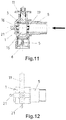
- the duct of the tubular bushing (5) is arranged to face the duct (17) provided with a minimum flow bushing (19), as shown in Figures 11 and 12 , such that only a minimum amount of the flow arriving at and entering through the tubular bushing (5) passes through the ball (3) to the duct (6), being able to create with said position a supply for users for only basic needs in special situations, such as non-payment of water bills, temporary vacancy of the home being supplied, etc.
- a band (20) associated with the operating lever (11) for rotating the ball (3) by means of the pin (8), said band (20) being intended to form a sealed retention of the tap in any of the functional positions, pivots (21) provided with a hole being provided in the body (1) of the tap, in which hole the free end of the band (20) can be selectively fitted and assured with a sealing cord to immobilize the tap in the desired functional position.
- the tap can be configured in any shape to better adapt to the applications for which it is intended without this altering the functional concepts forming the object of the invention in reference to the possibility of selecting an open flow position, a closed flow position, a restricted flow position and a minimum flow position, for the applications of use.
- the body (1) of the tap can form, for example, a bent prolongation (27) in the lower part for horizontally projecting the outlet duct (6), as depicted in Figure 13 .
Claims (4)
- Hahn für Wasserversorgungsrohre, der von einem Körper (1) gebildet ist, in welchem eine Kugel (3) untergebracht ist, die als wasserfeste Baugruppe und mit der Möglichkeit, eine Drehung auszuführen, angeordnet ist, um geöffnete und geschlossene Durchflusspositionen im Hahn zwischen einem Einlasskanal und einem Auslasskanal zu bilden, wobei die Kugel (3) einen ersten Kanal (14) aufweist, der sich von einem Seitenbereich zu einem Mittelbereich erstreckt, von wo aus es mit einem zweiten Kanal (15) weitergeht, welcher sich senkrecht nach unten gerichtet öffnet,
dadurch gekennzeichnet, dass
zwei weitere kleinere Kanäle (16 und 17) von unterschiedlichen Durchmessern sich zum ersten Kanal (14) hin senkrecht von jeweiligen Seitenbereichen öffnen, der zweite Kanal (15) zum unteren Teil einem Auslasskanal (6), der den Körper (1) des Hahns festlegt, zugewandt geöffnet ist, während je nach Drehung der Kugel (3) der erste Kanal (14) oder einer der kleineren Kanäle (16 und 17) oder der Blindteil gegenüber dem ersten Kanal (14) so angeordnet werden können, dass sie einem Einlasskanal gegenüber liegen, der von einer röhrenförmigen Buchse (5) gebildet wird, die mit dem Körper (1) des Hahns verbunden ist, um jeweils eine geöffnete Durchflussposition, eine beschränkte Durchflussposition, eine minimale Durchflussposition oder eine geschlossene Durchflussposition zu bilden, und
wobei jeweilige Teflon (™)-Buchsen (18 und 19) in den kleineren Öffnungen (16 und 17) angeordnet sind, die in den Seiten der Kugel (3) geöffnet sind, wodurch unterschiedliche Durchflussdurchmesser in den Öffnungen (16 und 17) festgelegt werden. - Hahn für Wasserversorgungsrohre nach Anspruch 1, dadurch gekennzeichnet, dass die funktionalen geöffneten Durchfluss-, beschränkten Durchfluss-, minimalen Durchfluss- und geschlossenen Durchflusspositionen mittels fortlaufender 90°-Drehungen der Kugel (3) in deren Baugruppengehäuse in eine Richtung festgelegt werden.
- Hahn für Wasserversorgungsrohre nach Anspruch 1, dadurch gekennzeichnet, dass ein Stift (8), der einen Bedienhebel (11) zur Drehung umfasst, mit der Kugel (3) verbunden angeordnet ist, wobei ein Band (20), welches mit Bezug zu Zapfen (21) des Körpers (1) eingerichtet sein kann, um jede der funktionalen Positionen des Hahns abzudichten, mit dem Hebel (11) verbunden ist.
- Hahn für Wasserversorgungsrohre nach Anspruch 1, dadurch gekennzeichnet, dass ein Rückschlagventil (22), welches eine Einbahn-Flussrichtung durch den Hahn festlegt, im Auslasskanal (6) angeordnet ist.
Applications Claiming Priority (2)
| Application Number | Priority Date | Filing Date | Title |
|---|---|---|---|
| ES201030603A ES2368233B1 (es) | 2010-04-26 | 2010-04-26 | Llave para conducciones de suministro de agua. |
| PCT/ES2011/000071 WO2011135119A1 (es) | 2010-04-26 | 2011-03-14 | Llave para conducciones de suministro de agua |
Publications (3)
| Publication Number | Publication Date |
|---|---|
| EP2565502A1 EP2565502A1 (de) | 2013-03-06 |
| EP2565502A4 EP2565502A4 (de) | 2014-09-10 |
| EP2565502B1 true EP2565502B1 (de) | 2017-05-31 |
Family
ID=44851681
Family Applications (1)
| Application Number | Title | Priority Date | Filing Date |
|---|---|---|---|
| EP11774434.2A Not-in-force EP2565502B1 (de) | 2010-04-26 | 2011-03-14 | Hahn für wasserzufuhrrohre |
Country Status (3)
| Country | Link |
|---|---|
| EP (1) | EP2565502B1 (de) |
| ES (1) | ES2368233B1 (de) |
| WO (1) | WO2011135119A1 (de) |
Families Citing this family (6)
| Publication number | Priority date | Publication date | Assignee | Title |
|---|---|---|---|---|
| ES2399701B1 (es) * | 2011-04-05 | 2013-12-12 | Rafael Alcaráz Sencianes | Llave de tres posiciones para suministros de agua. |
| ITMI20120118U1 (it) | 2012-03-22 | 2013-09-23 | Pettinaroli Flii Spa | Valvola di bilanciamento automatica a sfera |
| CN102966764A (zh) * | 2012-11-16 | 2013-03-13 | 大连民族学院 | 一种水龙头 |
| DE102014218151B4 (de) * | 2014-09-10 | 2016-05-25 | Tsg Technische Service Gesellschaft Mbh | Sicherungsvorrichtung |
| CN104595549B (zh) * | 2014-11-14 | 2017-03-08 | 宁波敏宝卫浴五金水暖洁具有限公司 | 一种龙头的安装结构及使用该安装结构的龙头 |
| IT202100024959A1 (it) * | 2021-09-29 | 2023-03-29 | Greiner Spa | Valvola |
Family Cites Families (10)
| Publication number | Priority date | Publication date | Assignee | Title |
|---|---|---|---|---|
| ES157607Y (es) * | 1970-04-02 | 1971-03-01 | Bataller Camps Jaime | Valvula de descarga para inodoros |
| JPS5114825U (de) * | 1974-07-17 | 1976-02-03 | ||
| JPS5913170A (ja) * | 1982-07-14 | 1984-01-23 | Tlv Co Ltd | 多方向ボ−ル弁 |
| IT8422417V0 (it) * | 1984-06-27 | 1984-06-27 | Romanelli Antonio | Rubinetto a sfera perfezionato. |
| IT1237988B (it) * | 1989-10-20 | 1993-06-19 | Riccardo Ferrero | Valvola a sfera a tre e a quattro vie, perfezionata |
| DE9205469U1 (de) * | 1992-04-22 | 1992-07-23 | Hans Sasserath & Co Kg, 4052 Korschenbroich, De | |
| US5937890A (en) * | 1998-01-09 | 1999-08-17 | Griswold Controls, Inc. | Insert for flow throttling ball valves |
| DE19812272A1 (de) * | 1998-03-09 | 1999-10-21 | Lovato Gmbh | Sicherheitsanschlußstück zum Anschließen eines Ausdehnungsgefäßes an einen geschlossenen Fluidkreislauf |
| DE102005010139B4 (de) * | 2004-12-29 | 2013-11-28 | Hans Sasserath & Co. Kg | Rohrtrenneranordnung |
| ITMI20061416A1 (it) * | 2006-07-20 | 2008-01-21 | Renato Colombo | Collettore per impianti di distribuzione di liquidi o di gas,a ridotto ingombro complessivo. |
-
2010
- 2010-04-26 ES ES201030603A patent/ES2368233B1/es not_active Expired - Fee Related
-
2011
- 2011-03-14 WO PCT/ES2011/000071 patent/WO2011135119A1/es active Application Filing
- 2011-03-14 EP EP11774434.2A patent/EP2565502B1/de not_active Not-in-force
Also Published As
| Publication number | Publication date |
|---|---|
| WO2011135119A9 (es) | 2012-01-05 |
| ES2368233A1 (es) | 2011-11-15 |
| WO2011135119A1 (es) | 2011-11-03 |
| EP2565502A1 (de) | 2013-03-06 |
| ES2368233B1 (es) | 2012-09-10 |
| EP2565502A4 (de) | 2014-09-10 |
Similar Documents
| Publication | Publication Date | Title |
|---|---|---|
| EP2565502B1 (de) | Hahn für wasserzufuhrrohre | |
| CN107690543B (zh) | 具有旁通回路的多通阀 | |
| EP3306151A1 (de) | Ventilelement mit verbessertem flüssigkeitsfluss und steuerung | |
| CN104806779B (zh) | 流体阀组件和用于流体阀组件的密封套筒 | |
| CN107345581B (zh) | 球阀装置及其阀球 | |
| EP2626605B1 (de) | Ventil mit einem Bypasskanal | |
| KR102324891B1 (ko) | 유로 전환 밸브 | |
| EP2696115B1 (de) | Dreistellungsventil für wasserversorgungssysteme | |
| EP3017219B1 (de) | Temperaturstellventil | |
| KR20090077686A (ko) | 3 방향 볼 밸브 | |
| CN204647386U (zh) | 流体阀组件和用于流体阀组件的密封套筒 | |
| US6926249B2 (en) | Precision modulating globe valve | |
| EP3311048A1 (de) | Kugelventilanordnung | |
| EP1489342B1 (de) | Dreiwegeventil | |
| RU2215220C2 (ru) | Вентиль, в частности вентиль радиатора отопления | |
| EP3067597A1 (de) | Flussregelventil | |
| EP3835632B1 (de) | Ventil mit bypasskanal | |
| EP2085670A1 (de) | Bypass-Klappe | |
| CN214305420U (zh) | 流体汇集器和包括该流体汇集器的流体分集组件 | |
| KR20110008209U (ko) | 밸브 일체형 엘보 | |
| CN111765265B (zh) | 一种旋塞阀 | |
| CA2243433C (en) | Flow valve | |
| KR100512578B1 (ko) | 밸브를 위한 디스크 기구 및 그를 사용한 게이트 밸브 및글로브 밸브 | |
| JP5220364B2 (ja) | 複合弁 | |
| EP3546830A1 (de) | Gashahn mit sicherheitsventil für ein gaskochgerät und gaskochgerät mit besagtem gashahn |
Legal Events
| Date | Code | Title | Description |
|---|---|---|---|
| PUAI | Public reference made under article 153(3) epc to a published international application that has entered the european phase |
Free format text: ORIGINAL CODE: 0009012 |
|
| 17P | Request for examination filed |
Effective date: 20121120 |
|
| AK | Designated contracting states |
Kind code of ref document: A1 Designated state(s): AL AT BE BG CH CY CZ DE DK EE ES FI FR GB GR HR HU IE IS IT LI LT LU LV MC MK MT NL NO PL PT RO RS SE SI SK SM TR |
|
| DAX | Request for extension of the european patent (deleted) | ||
| A4 | Supplementary search report drawn up and despatched |
Effective date: 20140812 |
|
| RIC1 | Information provided on ipc code assigned before grant |
Ipc: F16K 31/52 20060101ALI20140806BHEP Ipc: F16K 11/087 20060101AFI20140806BHEP Ipc: F16K 5/10 20060101ALI20140806BHEP Ipc: F16K 35/12 20060101ALI20140806BHEP Ipc: F16K 5/06 20060101ALI20140806BHEP Ipc: F16K 17/04 20060101ALI20140806BHEP Ipc: F16K 15/18 20060101ALI20140806BHEP |
|
| GRAP | Despatch of communication of intention to grant a patent |
Free format text: ORIGINAL CODE: EPIDOSNIGR1 |
|
| INTG | Intention to grant announced |
Effective date: 20161208 |
|
| GRAS | Grant fee paid |
Free format text: ORIGINAL CODE: EPIDOSNIGR3 |
|
| GRAA | (expected) grant |
Free format text: ORIGINAL CODE: 0009210 |
|
| AK | Designated contracting states |
Kind code of ref document: B1 Designated state(s): AL AT BE BG CH CY CZ DE DK EE ES FI FR GB GR HR HU IE IS IT LI LT LU LV MC MK MT NL NO PL PT RO RS SE SI SK SM TR |
|
| REG | Reference to a national code |
Ref country code: CH Ref legal event code: EP Ref country code: GB Ref legal event code: FG4D |
|
| REG | Reference to a national code |
Ref country code: AT Ref legal event code: REF Ref document number: 897800 Country of ref document: AT Kind code of ref document: T Effective date: 20170615 |
|
| REG | Reference to a national code |
Ref country code: IE Ref legal event code: FG4D |
|
| REG | Reference to a national code |
Ref country code: DE Ref legal event code: R096 Ref document number: 602011038380 Country of ref document: DE |
|
| REG | Reference to a national code |
Ref country code: NL Ref legal event code: MP Effective date: 20170531 |
|
| REG | Reference to a national code |
Ref country code: LT Ref legal event code: MG4D |
|
| REG | Reference to a national code |
Ref country code: AT Ref legal event code: MK05 Ref document number: 897800 Country of ref document: AT Kind code of ref document: T Effective date: 20170531 |
|
| PG25 | Lapsed in a contracting state [announced via postgrant information from national office to epo] |
Ref country code: ES Free format text: LAPSE BECAUSE OF FAILURE TO SUBMIT A TRANSLATION OF THE DESCRIPTION OR TO PAY THE FEE WITHIN THE PRESCRIBED TIME-LIMIT Effective date: 20170531 Ref country code: NO Free format text: LAPSE BECAUSE OF FAILURE TO SUBMIT A TRANSLATION OF THE DESCRIPTION OR TO PAY THE FEE WITHIN THE PRESCRIBED TIME-LIMIT Effective date: 20170831 Ref country code: GR Free format text: LAPSE BECAUSE OF FAILURE TO SUBMIT A TRANSLATION OF THE DESCRIPTION OR TO PAY THE FEE WITHIN THE PRESCRIBED TIME-LIMIT Effective date: 20170901 Ref country code: HR Free format text: LAPSE BECAUSE OF FAILURE TO SUBMIT A TRANSLATION OF THE DESCRIPTION OR TO PAY THE FEE WITHIN THE PRESCRIBED TIME-LIMIT Effective date: 20170531 Ref country code: AT Free format text: LAPSE BECAUSE OF FAILURE TO SUBMIT A TRANSLATION OF THE DESCRIPTION OR TO PAY THE FEE WITHIN THE PRESCRIBED TIME-LIMIT Effective date: 20170531 Ref country code: LT Free format text: LAPSE BECAUSE OF FAILURE TO SUBMIT A TRANSLATION OF THE DESCRIPTION OR TO PAY THE FEE WITHIN THE PRESCRIBED TIME-LIMIT Effective date: 20170531 Ref country code: FI Free format text: LAPSE BECAUSE OF FAILURE TO SUBMIT A TRANSLATION OF THE DESCRIPTION OR TO PAY THE FEE WITHIN THE PRESCRIBED TIME-LIMIT Effective date: 20170531 |
|
| PG25 | Lapsed in a contracting state [announced via postgrant information from national office to epo] |
Ref country code: SE Free format text: LAPSE BECAUSE OF FAILURE TO SUBMIT A TRANSLATION OF THE DESCRIPTION OR TO PAY THE FEE WITHIN THE PRESCRIBED TIME-LIMIT Effective date: 20170531 Ref country code: NL Free format text: LAPSE BECAUSE OF FAILURE TO SUBMIT A TRANSLATION OF THE DESCRIPTION OR TO PAY THE FEE WITHIN THE PRESCRIBED TIME-LIMIT Effective date: 20170531 Ref country code: LV Free format text: LAPSE BECAUSE OF FAILURE TO SUBMIT A TRANSLATION OF THE DESCRIPTION OR TO PAY THE FEE WITHIN THE PRESCRIBED TIME-LIMIT Effective date: 20170531 Ref country code: RS Free format text: LAPSE BECAUSE OF FAILURE TO SUBMIT A TRANSLATION OF THE DESCRIPTION OR TO PAY THE FEE WITHIN THE PRESCRIBED TIME-LIMIT Effective date: 20170531 Ref country code: IS Free format text: LAPSE BECAUSE OF FAILURE TO SUBMIT A TRANSLATION OF THE DESCRIPTION OR TO PAY THE FEE WITHIN THE PRESCRIBED TIME-LIMIT Effective date: 20170930 Ref country code: BG Free format text: LAPSE BECAUSE OF FAILURE TO SUBMIT A TRANSLATION OF THE DESCRIPTION OR TO PAY THE FEE WITHIN THE PRESCRIBED TIME-LIMIT Effective date: 20170831 |
|
| PG25 | Lapsed in a contracting state [announced via postgrant information from national office to epo] |
Ref country code: DK Free format text: LAPSE BECAUSE OF FAILURE TO SUBMIT A TRANSLATION OF THE DESCRIPTION OR TO PAY THE FEE WITHIN THE PRESCRIBED TIME-LIMIT Effective date: 20170531 Ref country code: RO Free format text: LAPSE BECAUSE OF FAILURE TO SUBMIT A TRANSLATION OF THE DESCRIPTION OR TO PAY THE FEE WITHIN THE PRESCRIBED TIME-LIMIT Effective date: 20170531 Ref country code: EE Free format text: LAPSE BECAUSE OF FAILURE TO SUBMIT A TRANSLATION OF THE DESCRIPTION OR TO PAY THE FEE WITHIN THE PRESCRIBED TIME-LIMIT Effective date: 20170531 Ref country code: SK Free format text: LAPSE BECAUSE OF FAILURE TO SUBMIT A TRANSLATION OF THE DESCRIPTION OR TO PAY THE FEE WITHIN THE PRESCRIBED TIME-LIMIT Effective date: 20170531 Ref country code: CZ Free format text: LAPSE BECAUSE OF FAILURE TO SUBMIT A TRANSLATION OF THE DESCRIPTION OR TO PAY THE FEE WITHIN THE PRESCRIBED TIME-LIMIT Effective date: 20170531 |
|
| PG25 | Lapsed in a contracting state [announced via postgrant information from national office to epo] |
Ref country code: PL Free format text: LAPSE BECAUSE OF FAILURE TO SUBMIT A TRANSLATION OF THE DESCRIPTION OR TO PAY THE FEE WITHIN THE PRESCRIBED TIME-LIMIT Effective date: 20170531 Ref country code: SM Free format text: LAPSE BECAUSE OF FAILURE TO SUBMIT A TRANSLATION OF THE DESCRIPTION OR TO PAY THE FEE WITHIN THE PRESCRIBED TIME-LIMIT Effective date: 20170531 |
|
| REG | Reference to a national code |
Ref country code: DE Ref legal event code: R097 Ref document number: 602011038380 Country of ref document: DE |
|
| REG | Reference to a national code |
Ref country code: FR Ref legal event code: PLFP Year of fee payment: 8 |
|
| PLBE | No opposition filed within time limit |
Free format text: ORIGINAL CODE: 0009261 |
|
| STAA | Information on the status of an ep patent application or granted ep patent |
Free format text: STATUS: NO OPPOSITION FILED WITHIN TIME LIMIT |
|
| 26N | No opposition filed |
Effective date: 20180301 |
|
| PG25 | Lapsed in a contracting state [announced via postgrant information from national office to epo] |
Ref country code: SI Free format text: LAPSE BECAUSE OF FAILURE TO SUBMIT A TRANSLATION OF THE DESCRIPTION OR TO PAY THE FEE WITHIN THE PRESCRIBED TIME-LIMIT Effective date: 20170531 |
|
| PGFP | Annual fee paid to national office [announced via postgrant information from national office to epo] |
Ref country code: FR Payment date: 20180328 Year of fee payment: 8 |
|
| PGFP | Annual fee paid to national office [announced via postgrant information from national office to epo] |
Ref country code: IT Payment date: 20180404 Year of fee payment: 8 |
|
| REG | Reference to a national code |
Ref country code: DE Ref legal event code: R119 Ref document number: 602011038380 Country of ref document: DE |
|
| REG | Reference to a national code |
Ref country code: CH Ref legal event code: PL |
|
| GBPC | Gb: european patent ceased through non-payment of renewal fee |
Effective date: 20180314 |
|
| PG25 | Lapsed in a contracting state [announced via postgrant information from national office to epo] |
Ref country code: MC Free format text: LAPSE BECAUSE OF FAILURE TO SUBMIT A TRANSLATION OF THE DESCRIPTION OR TO PAY THE FEE WITHIN THE PRESCRIBED TIME-LIMIT Effective date: 20170531 |
|
| REG | Reference to a national code |
Ref country code: BE Ref legal event code: MM Effective date: 20180331 |
|
| REG | Reference to a national code |
Ref country code: IE Ref legal event code: MM4A |
|
| PG25 | Lapsed in a contracting state [announced via postgrant information from national office to epo] |
Ref country code: LU Free format text: LAPSE BECAUSE OF NON-PAYMENT OF DUE FEES Effective date: 20180314 |
|
| PG25 | Lapsed in a contracting state [announced via postgrant information from national office to epo] |
Ref country code: IE Free format text: LAPSE BECAUSE OF NON-PAYMENT OF DUE FEES Effective date: 20180314 Ref country code: DE Free format text: LAPSE BECAUSE OF NON-PAYMENT OF DUE FEES Effective date: 20181002 |
|
| PG25 | Lapsed in a contracting state [announced via postgrant information from national office to epo] |
Ref country code: LI Free format text: LAPSE BECAUSE OF NON-PAYMENT OF DUE FEES Effective date: 20180331 Ref country code: GB Free format text: LAPSE BECAUSE OF NON-PAYMENT OF DUE FEES Effective date: 20180314 Ref country code: BE Free format text: LAPSE BECAUSE OF NON-PAYMENT OF DUE FEES Effective date: 20180331 Ref country code: CH Free format text: LAPSE BECAUSE OF NON-PAYMENT OF DUE FEES Effective date: 20180331 |
|
| PG25 | Lapsed in a contracting state [announced via postgrant information from national office to epo] |
Ref country code: MT Free format text: LAPSE BECAUSE OF NON-PAYMENT OF DUE FEES Effective date: 20180314 |
|
| PG25 | Lapsed in a contracting state [announced via postgrant information from national office to epo] |
Ref country code: IT Free format text: LAPSE BECAUSE OF NON-PAYMENT OF DUE FEES Effective date: 20190314 Ref country code: FR Free format text: LAPSE BECAUSE OF NON-PAYMENT OF DUE FEES Effective date: 20190331 |
|
| PG25 | Lapsed in a contracting state [announced via postgrant information from national office to epo] |
Ref country code: TR Free format text: LAPSE BECAUSE OF FAILURE TO SUBMIT A TRANSLATION OF THE DESCRIPTION OR TO PAY THE FEE WITHIN THE PRESCRIBED TIME-LIMIT Effective date: 20170531 |
|
| PG25 | Lapsed in a contracting state [announced via postgrant information from national office to epo] |
Ref country code: PT Free format text: LAPSE BECAUSE OF FAILURE TO SUBMIT A TRANSLATION OF THE DESCRIPTION OR TO PAY THE FEE WITHIN THE PRESCRIBED TIME-LIMIT Effective date: 20170531 Ref country code: HU Free format text: LAPSE BECAUSE OF FAILURE TO SUBMIT A TRANSLATION OF THE DESCRIPTION OR TO PAY THE FEE WITHIN THE PRESCRIBED TIME-LIMIT; INVALID AB INITIO Effective date: 20110314 |
|
| PG25 | Lapsed in a contracting state [announced via postgrant information from national office to epo] |
Ref country code: CY Free format text: LAPSE BECAUSE OF FAILURE TO SUBMIT A TRANSLATION OF THE DESCRIPTION OR TO PAY THE FEE WITHIN THE PRESCRIBED TIME-LIMIT Effective date: 20170531 Ref country code: MK Free format text: LAPSE BECAUSE OF NON-PAYMENT OF DUE FEES Effective date: 20170531 |
|
| PG25 | Lapsed in a contracting state [announced via postgrant information from national office to epo] |
Ref country code: AL Free format text: LAPSE BECAUSE OF FAILURE TO SUBMIT A TRANSLATION OF THE DESCRIPTION OR TO PAY THE FEE WITHIN THE PRESCRIBED TIME-LIMIT Effective date: 20170531 |