EP2565381A2 - Assembly and method preventing tie shaft to unscrew - Google Patents
Assembly and method preventing tie shaft to unscrew Download PDFInfo
- Publication number
- EP2565381A2 EP2565381A2 EP12181560A EP12181560A EP2565381A2 EP 2565381 A2 EP2565381 A2 EP 2565381A2 EP 12181560 A EP12181560 A EP 12181560A EP 12181560 A EP12181560 A EP 12181560A EP 2565381 A2 EP2565381 A2 EP 2565381A2
- Authority
- EP
- European Patent Office
- Prior art keywords
- threads
- downstream
- abutment member
- upstream
- tie shaft
- Prior art date
- Legal status (The legal status is an assumption and is not a legal conclusion. Google has not performed a legal analysis and makes no representation as to the accuracy of the status listed.)
- Granted
Links
Images


Classifications
-
- F—MECHANICAL ENGINEERING; LIGHTING; HEATING; WEAPONS; BLASTING
- F01—MACHINES OR ENGINES IN GENERAL; ENGINE PLANTS IN GENERAL; STEAM ENGINES
- F01D—NON-POSITIVE DISPLACEMENT MACHINES OR ENGINES, e.g. STEAM TURBINES
- F01D5/00—Blades; Blade-carrying members; Heating, heat-insulating, cooling or antivibration means on the blades or the members
- F01D5/02—Blade-carrying members, e.g. rotors
- F01D5/06—Rotors for more than one axial stage, e.g. of drum or multiple disc type; Details thereof, e.g. shafts, shaft connections
- F01D5/066—Connecting means for joining rotor-discs or rotor-elements together, e.g. by a central bolt, by clamps
-
- F—MECHANICAL ENGINEERING; LIGHTING; HEATING; WEAPONS; BLASTING
- F05—INDEXING SCHEMES RELATING TO ENGINES OR PUMPS IN VARIOUS SUBCLASSES OF CLASSES F01-F04
- F05D—INDEXING SCHEME FOR ASPECTS RELATING TO NON-POSITIVE-DISPLACEMENT MACHINES OR ENGINES, GAS-TURBINES OR JET-PROPULSION PLANTS
- F05D2260/00—Function
- F05D2260/30—Retaining components in desired mutual position
- F05D2260/31—Retaining bolts or nuts
-
- Y—GENERAL TAGGING OF NEW TECHNOLOGICAL DEVELOPMENTS; GENERAL TAGGING OF CROSS-SECTIONAL TECHNOLOGIES SPANNING OVER SEVERAL SECTIONS OF THE IPC; TECHNICAL SUBJECTS COVERED BY FORMER USPC CROSS-REFERENCE ART COLLECTIONS [XRACs] AND DIGESTS
- Y10—TECHNICAL SUBJECTS COVERED BY FORMER USPC
- Y10T—TECHNICAL SUBJECTS COVERED BY FORMER US CLASSIFICATION
- Y10T29/00—Metal working
- Y10T29/49—Method of mechanical manufacture
- Y10T29/49316—Impeller making
- Y10T29/4932—Turbomachine making
Definitions
- This application relates to a gas turbine engine including compressor and turbine rotors assembled using a tie shaft connection.
- Gas turbine engines typically include a compressor, which compresses air and delivers it downstream into a combustion section. The air is mixed with fuel in the combustion section and combusted. Products of this combustion pass downstream over turbine rotors, causing the turbine rotors to rotate.
- the compressor section is provided with a plurality of rotor serial stages, or rotor sections.
- these stages were joined sequentially, one to another, into an inseparable assembly by welding, or into a separable assembly by bolting using bolt flanges, or other structure to receive the attachment bolts.
- a gas turbine engine has a plurality of compressor rotors, as well as a plurality of turbine rotors.
- a tie shaft of the engine is constrained to rotate with the compressor and turbine rotors during normal operating conditions.
- an upstream hub is located upstream of the compressor rotors and is in threaded engagement with the tie shaft. The threads of the upstream hub are handed in a first manner when viewed from an upstream location.
- a downstream abutment member is positioned downstream of the turbine rotors and is also in threaded engagement with the tie shaft. The threads of the downstream abutment member are handed in the first manner when viewed from a downstream location. Further disclosed is a method of assembling the gas turbine engine.
- Figure 1 schematically shows an exemplary section of a gas turbine engine 10, in particular a high pressure spool, incorporating a combustion section 12, shown schematically, a compressor section 14 having a plurality of compressor rotors 16 defining a compressor stack, and a turbine section 18 having a plurality of turbine rotors 20 defining a turbine stack.
- an upstream hub 22 has a threaded engagement with a tie shaft 24 upstream of the compressor rotors 16.
- a downstream hub 26 is positioned at a downstream side of the compressor stack, and contacts a downstream-most compressor rotor 16D.
- the stack of compressor rotors is thus sandwiched between the upstream and downstream hubs 22, 26, and is secured by a mid lock nut, or mid abutment member, 28.
- Downstream hub 26 abuts the turbine stack, which is held against a turbine lock nut, or abutment member, 30.
- a low pressure turbine may be arranged to the right (or downstream) of the turbine lock nut 30.
- the mid and turbine lock nuts 28, 30 and the upstream hub 22 are in threaded engagement with the tie shaft 24, as discussed with reference to Figures 2-4 , below.
- the upstream hub 22 may include a plurality of threads 32 having load flanks 34L and clearance flanks 34C.
- the tie shaft 24 may thus include complementary front threads 36 having load flanks 38L and clearance flanks 38C.
- the load flanks 34L, 38L abut one another, as shown, such that the upstream hub 22 applies a load toward the compressor stacks.
- the load flanks 34L, 38L are generally perpendicular to the engine axis A, and may be inclined approximately 3° relative to the perpendicular to provide an adequate contact surface between load flanks 34L, 38L.
- the clearance flanks 34C, 38C may be inclined approximately 30° relative to the perpendicular. These angles of inclination may be varied as desired, and are simply exemplary.
- the threads 32, 36 are right-handed threads. That is, viewing the upstream hub 22 from an upstream location (e.g., from left to right in Figure 2 ), clockwise CW rotation of the upstream hub 22 relative to the tie shaft 24 urges the upstream hub 22 in direction D 1 relative to the tie shaft 24. In Figure 2 , however, this relative movement of the upstream hub 22 is prevented by contact between the tie shaft 24 and the abutment point 40 of the upstream hub 22.
- the pitch of the threads 32, 36 may be 12 TPI (threads-per-inch) (roughly 4.7 threads-per-cm). This TPI is simply an example.
- FIG 3 shows the engagement between the tie shaft 24 and the mid lock nut 28.
- the downstream hub 26 and the mid lock nut 28, in combination with the upstream hub 22, are arranged to provide a pre-load to the compressor stage.
- the shown mid lock nut 28 is threaded onto the tie shaft 24 from a direction D 2 , and includes right-handed threads 42 (e.g., the threads are right-handed when viewed from a downstream location, or from right-to-left in Figure 3 ).
- Mid threads 46 of the tie shaft 24 may be similarly handed to correspond to the threads 42. After assembly, the load flank 44L of the threads 42 abuts the load flank 48L of the mid threads 46.
- the pitch of the threads 42, 46 may be selected to be coarser than that of the threads 32, 36, such as 10 TPI (roughly 3.9 threads-per-cm). Again, this TPI is simply an example.
- An optional lock washer 50 may be utilized for added safety.
- Figure 4 shows the turbine lock nut 30 in threaded engagement with the tie shaft 24 at a point downstream of the turbine stack. Similar to the mid lock nut 28, the turbine lock nut may also be threaded onto the tie shaft from a direction D 2 and includes right-handed threads. Threads 52 of the turbine lock nut 30 may further include load flanks 54L configured to abut load flanks 58L of the turbine threads 56 of the tie shaft 24. An optional lock washer 60 may be used in connection with the turbine lock nut 30.
- the threads 52, 56 may be coarser than the threads 32, 36. As shown, the pitch of the threads 52, 56 is 10 TPI (roughly 3.9 threads-per-cm). Again, this TPI is exemplary. As will be appreciated from the exemplary assembly method shown in Figures 5-6 , the turbine lock nut 30, in combination with the upstream hub 22, is responsible for a significant portion of the pre-load on the compressor and turbine stacks.
- clearance flanks 46C, 48C and 54C, 58C may be inclined at an angle of approximately 45° relative to a direction perpendicular to the engine axis A.
- the load flanks 46L, 48L, 54L, 58L may be arranged closer to the perpendicular direction, such as being inclined at approximately 7° thereto. Again, these angles are examples.
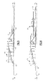
- Figures 5-6 show the assembly sequence of the gas turbine engine 10 with the disclosed arrangement.
- the single headed arrows shown in these Figures illustrate an applied force, while the double-headed arrows illustrate internal forces.
- the upstream hub 22 is assembled, by way of threads, to the tie shaft 24 while the compressor rotors 16 and downstream hub 26 are stacked together using the mid lock nut 28 to apply an axial pre-load force holding the rotors against the upstream hub 22 and ensuring the necessary friction to transmit torque.
- An internal compression load will be created in the rotors stack to react the tension load in the tie shaft 24 (e.g., as a consequence of applying successive stretches to the tie shaft 24 and the relevant rotor stack, then constraining the assembly by locking the nuts 28 and 30).
- the subsequent step includes assembling the turbine rotors 20, and using turbine lock nut 30 to secure the new assembly by applying an axial pre-load force holding the compressor and turbine rotors 16, 20 together and ensuring the necessary friction to transmit torque.
- a secondary load path is created with internal compression load in the turbine stack and tension load in the downstream end of the tie shaft 24; the internal compression load in the compressor rotors stack is also augmented.
- the majority of the pre-load applied to the compressor and turbine rotors 16, 20 is carried by the upstream hub 22 and the turbine lock nut 30. While the mid lock nut 28 does carry some of that overall pre-load, the mid lock nut 28 is primarily useful during assembly of the compressor stage.
- an additional nut may be driven to hold a bearing and seal package against the turbine rotors 20 and augment the final stack preload to ensure the necessary friction to transmit torque.
- the turbines can be held together by the lock nut 30 alone.
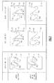
- Figure 7 is a chart representative of the threaded joints of Figures 2-4 after both (1) assembly and (2) initial tie shaft unwinding.
- the threaded joints are positioned in the same manner shown in Figures 2-4 .
- the load flanks 34L, 38L, 44L, 48L, 54L and 58L of the respective threads abut one another to maintain a pre-load on the compressor and turbine stacks.
- the threaded joints will also be in this position during normal engine operating conditions. That is, during normal engine operating conditions, the upstream hub 22, the mid lock nut 28 and the turbine lock nut 30 are configured to rotate with the tie shaft 24.
- the turbine engine 10 is configured for counter-clockwise CCW rotation about the engine axis A, and thus the upstream hub 22, the lock nuts 28, 30 and the tie shaft 24 all rotate together in the counter-clockwise CCW direction.
- the clockwise and counter-clockwise CW, CCW conventions used herein are used to aid in understanding of this disclosure and should not be interpreted as contradicting any other accepted conventions.
- the tie shaft may rotate clockwise CW relative to the counter-clockwise CCW rotation of the turbine engine 10, upstream hub 22 and the lock nuts 28, 30. Given the right-handed orientation of the threads 32, 36 of the upstream hub 22, this relative rotation will urge the tie shaft 24 in a direction D 1 generally away from the upstream hub 22.
- the relative clockwise CW rotation of the tie shaft 24 actually tightens the lock nuts 28, 30 relative to the tie shaft 24 and prevents the tie shaft from unwinding from the upstream hub 22. That is, the coarser threads 42, 46, 52, 56 urge the tie shaft 24 further in direction D 2 than the finer threads 32, 36 urge the tie shaft 24 in the direction D 1 . Stated another way, the finer threads 32, 36 attempt to move the tie shaft 24 more slowly than the coarser threads 42, 46, 52, 56 would otherwise allow.
- the tie shaft 24 may axially move a distance D 3 between the clearance flanks 44C, 48C, 54C, 58C, this axial movement is relatively minor, and will not result in any substantial loss in pre-load.
- the relative positions of the upstream hub 22 and the lock nuts 28, 30 remain substantially unchanged, even after the initial unwinding of the tie shaft 24, and therefore the pre-load is substantially maintained.
- the disclosed arrangement limits axial movement of the tie shaft 24 to the distance D 3 .
- the lock nuts 28, 30 urge the tie shaft 24 in a direction D 2 by way of engagement of the clearance flanks 44C, 48C, 54C, 58C, as represented in the row labeled "After Initial Tie Shaft Unwinding."
- threads 32, 36 have been shown and described as right-handed threads (when viewed from an upstream location) and the threads 42, 46, 52, 56 have been shown and described as being right-handed threads (when viewed from a downstream location) it is possible that the handedness of the threads could be reversed. That is, in a contemplated embodiment the threads 32, 36 could be left-handed when viewed from upstream, and the threads 42, 46, 52, 56 could be left-handed when viewed from downstream. In either case, the lock nuts 28, 30 would substantially prevent unwinding of the tie shaft 24 relative to the upstream hub 22.
- the threads 32, 36 may have a pitch of 12 TPI and the threads 42, 46, 52, 56 may have a coarser pitch of 10 TPI, other pitch combinations are contemplated herein, including other combinations whether the threads 32, 36 have a finer pitch that the threads 42, 46, 52, 56.
- the disclosed arrangement ensures that the compressor and turbine sections 14, 18 are reliably held together, and will be capable to resist the forces to be encountered during use, while still transmitting the necessary engine torque.
- the tie shaft is substantially prevented from unwinding, thus retaining the pre-load in the overall engine assembly, even in an attempted tie shaft unwinding condition. All these functions are accomplished within a minimal axial envelope and with the lowest locking hardware count.
Landscapes
- Engineering & Computer Science (AREA)
- Mechanical Engineering (AREA)
- General Engineering & Computer Science (AREA)
- Turbine Rotor Nozzle Sealing (AREA)
- Structures Of Non-Positive Displacement Pumps (AREA)
Abstract
And a corresponding assembling method for a gas turbine engine.
Description
- This application relates to a gas turbine engine including compressor and turbine rotors assembled using a tie shaft connection.
- Gas turbine engines are known, and typically include a compressor, which compresses air and delivers it downstream into a combustion section. The air is mixed with fuel in the combustion section and combusted. Products of this combustion pass downstream over turbine rotors, causing the turbine rotors to rotate.
- Typically, the compressor section is provided with a plurality of rotor serial stages, or rotor sections. Traditionally, these stages were joined sequentially, one to another, into an inseparable assembly by welding, or into a separable assembly by bolting using bolt flanges, or other structure to receive the attachment bolts.
- More recently, it has been proposed to eliminate the welded or bolted joints with a single coupling which applies an axial force, or pre-load, through the compressor and turbine rotors to hold them together and create the friction necessary to transmit torque. While not prior art, some of these assemblies have experienced an unwinding condition where that pre-load is substantially reduced or lost altogether.
- A gas turbine engine has a plurality of compressor rotors, as well as a plurality of turbine rotors. A tie shaft of the engine is constrained to rotate with the compressor and turbine rotors during normal operating conditions. Further, an upstream hub is located upstream of the compressor rotors and is in threaded engagement with the tie shaft. The threads of the upstream hub are handed in a first manner when viewed from an upstream location. A downstream abutment member is positioned downstream of the turbine rotors and is also in threaded engagement with the tie shaft. The threads of the downstream abutment member are handed in the first manner when viewed from a downstream location. Further disclosed is a method of assembling the gas turbine engine.
- These and other features of the present disclosure can be best understood from the following specification and drawings, the following of which is a brief description.
- The drawings can be briefly described as follows:
-
Figure 1 schematically shows a portion of an exemplary gas turbine engine; -
Figure 2 is a close-up view of the designated area inFigure 1 ; -
Figure 3 is a close-up view of the designated area inFigure 1 ; -
Figure 4 is a close-up view of the designated area inFigure 1 ; -
Figure 5 shows a first step in the assembly of the portion of the engine ofFigure 1 ; -
Figure 6 shows a second step in the assembly of the portion of the engine ofFigure 1 ; and -
Figure 7 is a chart representing the arrangement of the threaded joints ofFigures 2-4 after (1) assembly and (2) initial tie shaft unwinding. -
Figure 1 schematically shows an exemplary section of a gas turbine engine 10, in particular a high pressure spool, incorporating acombustion section 12, shown schematically, a compressor section 14 having a plurality ofcompressor rotors 16 defining a compressor stack, and aturbine section 18 having a plurality ofturbine rotors 20 defining a turbine stack. As shown, anupstream hub 22 has a threaded engagement with atie shaft 24 upstream of thecompressor rotors 16. Notably, there may be a low pressure compressor, and a fan section, to the left (or upstream) of theupstream hub 22. - A
downstream hub 26 is positioned at a downstream side of the compressor stack, and contacts adownstream-most compressor rotor 16D. The stack of compressor rotors is thus sandwiched between the upstream anddownstream hubs Downstream hub 26 abuts the turbine stack, which is held against a turbine lock nut, or abutment member, 30. A low pressure turbine may be arranged to the right (or downstream) of theturbine lock nut 30. The mid andturbine lock nuts upstream hub 22 are in threaded engagement with thetie shaft 24, as discussed with reference toFigures 2-4 , below. - Referring to
Figure 2 , theupstream hub 22 may include a plurality ofthreads 32 havingload flanks 34L andclearance flanks 34C. Thetie shaft 24 may thus include complementaryfront threads 36 havingload flanks 38L andclearance flanks 38C. After assembly, theload flanks upstream hub 22 applies a load toward the compressor stacks. Theload flanks load flanks - Notably, and in the example shown, the
threads upstream hub 22 from an upstream location (e.g., from left to right inFigure 2 ), clockwise CW rotation of theupstream hub 22 relative to thetie shaft 24 urges theupstream hub 22 in direction D1 relative to thetie shaft 24. InFigure 2 , however, this relative movement of theupstream hub 22 is prevented by contact between thetie shaft 24 and theabutment point 40 of theupstream hub 22. The pitch of thethreads -
Figure 3 shows the engagement between thetie shaft 24 and themid lock nut 28. As mentioned above, thedownstream hub 26 and themid lock nut 28, in combination with theupstream hub 22, are arranged to provide a pre-load to the compressor stage. The shownmid lock nut 28 is threaded onto thetie shaft 24 from a direction D2, and includes right-handed threads 42 (e.g., the threads are right-handed when viewed from a downstream location, or from right-to-left inFigure 3 ).Mid threads 46 of thetie shaft 24 may be similarly handed to correspond to thethreads 42. After assembly, theload flank 44L of thethreads 42 abuts theload flank 48L of themid threads 46. The pitch of thethreads threads optional lock washer 50 may be utilized for added safety. -
Figure 4 shows theturbine lock nut 30 in threaded engagement with thetie shaft 24 at a point downstream of the turbine stack. Similar to themid lock nut 28, the turbine lock nut may also be threaded onto the tie shaft from a direction D2 and includes right-handed threads.Threads 52 of theturbine lock nut 30 may further includeload flanks 54L configured toabut load flanks 58L of theturbine threads 56 of thetie shaft 24. Anoptional lock washer 60 may be used in connection with theturbine lock nut 30. - Similar to the
threads threads threads threads Figures 5-6 , theturbine lock nut 30, in combination with theupstream hub 22, is responsible for a significant portion of the pre-load on the compressor and turbine stacks. - Further, the
clearance flanks load flanks -
Figures 5-6 show the assembly sequence of the gas turbine engine 10 with the disclosed arrangement. The single headed arrows shown in these Figures illustrate an applied force, while the double-headed arrows illustrate internal forces. As shown inFigure 5 , initially, theupstream hub 22 is assembled, by way of threads, to thetie shaft 24 while thecompressor rotors 16 anddownstream hub 26 are stacked together using themid lock nut 28 to apply an axial pre-load force holding the rotors against theupstream hub 22 and ensuring the necessary friction to transmit torque. An internal compression load will be created in the rotors stack to react the tension load in the tie shaft 24 (e.g., as a consequence of applying successive stretches to thetie shaft 24 and the relevant rotor stack, then constraining the assembly by locking the nuts 28 and 30). - As shown in
Figure 6 , the subsequent step includes assembling theturbine rotors 20, and usingturbine lock nut 30 to secure the new assembly by applying an axial pre-load force holding the compressor andturbine rotors tie shaft 24; the internal compression load in the compressor rotors stack is also augmented. Notably, the majority of the pre-load applied to the compressor andturbine rotors upstream hub 22 and theturbine lock nut 30. While themid lock nut 28 does carry some of that overall pre-load, themid lock nut 28 is primarily useful during assembly of the compressor stage. - While not shown, an additional nut may be driven to hold a bearing and seal package against the
turbine rotors 20 and augment the final stack preload to ensure the necessary friction to transmit torque. Alternatively, the turbines can be held together by thelock nut 30 alone. -
Figure 7 is a chart representative of the threaded joints ofFigures 2-4 after both (1) assembly and (2) initial tie shaft unwinding. In the row labeled "After Assembly," the threaded joints are positioned in the same manner shown inFigures 2-4 . Notably, in this position the load flanks 34L, 38L, 44L, 48L, 54L and 58L of the respective threads abut one another to maintain a pre-load on the compressor and turbine stacks. The threaded joints will also be in this position during normal engine operating conditions. That is, during normal engine operating conditions, theupstream hub 22, themid lock nut 28 and theturbine lock nut 30 are configured to rotate with thetie shaft 24. In the example ofFigure 1 , the turbine engine 10 is configured for counter-clockwise CCW rotation about the engine axis A, and thus theupstream hub 22, thelock nuts tie shaft 24 all rotate together in the counter-clockwise CCW direction. Notably, the clockwise and counter-clockwise CW, CCW conventions used herein are used to aid in understanding of this disclosure and should not be interpreted as contradicting any other accepted conventions. - In an attempted tie shaft unwinding condition (e.g., during a sudden deceleration, or "snap" deceleration, of the turbine engine 10), the tie shaft may rotate clockwise CW relative to the counter-clockwise CCW rotation of the turbine engine 10,
upstream hub 22 and thelock nuts threads upstream hub 22, this relative rotation will urge thetie shaft 24 in a direction D1 generally away from theupstream hub 22. However, due to the arrangement of thelock nuts threads tie shaft 24 actually tightens thelock nuts tie shaft 24 and prevents the tie shaft from unwinding from theupstream hub 22. That is, thecoarser threads tie shaft 24 further in direction D2 than thefiner threads tie shaft 24 in the direction D1. Stated another way, thefiner threads tie shaft 24 more slowly than thecoarser threads - While the
tie shaft 24 may axially move a distance D3 between the clearance flanks 44C, 48C, 54C, 58C, this axial movement is relatively minor, and will not result in any substantial loss in pre-load. In fact, the relative positions of theupstream hub 22 and thelock nuts tie shaft 24, and therefore the pre-load is substantially maintained. Instead of unwinding altogether, the disclosed arrangement limits axial movement of thetie shaft 24 to the distance D3. Once thetie shaft 24 moves this relatively small distance, thelock nuts tie shaft 24 in a direction D2 by way of engagement of the clearance flanks 44C, 48C, 54C, 58C, as represented in the row labeled "After Initial Tie Shaft Unwinding." - While the
threads threads threads threads lock nuts tie shaft 24 relative to theupstream hub 22. - Further, while it has been mentioned that the
threads threads threads threads - The disclosed arrangement ensures that the compressor and
turbine sections 14, 18 are reliably held together, and will be capable to resist the forces to be encountered during use, while still transmitting the necessary engine torque. In particular, the tie shaft is substantially prevented from unwinding, thus retaining the pre-load in the overall engine assembly, even in an attempted tie shaft unwinding condition. All these functions are accomplished within a minimal axial envelope and with the lowest locking hardware count. - One of ordinary skill in this art would understand that the above-described embodiments are exemplary and non-limiting. That is, modifications of this disclosure would come within the scope of the claims. Accordingly, the following claims should be studied to determine their true scope and content.
Claims (15)
- A gas turbine engine (10) comprising:a plurality of compressor rotors (16);a plurality of turbine rotors (20);a tie shaft (24), the compressor and turbine rotors (16, 20) being constrained to rotate with the tie shaft (24) in a normal operating condition;an upstream hub (22) located upstream of the compressor rotors (16), the upstream hub (22) in threaded engagement with the tie shaft (24), threads (32) of the upstream hub (22) handed in a first manner when viewed from an upstream location; anda downstream abutment member (30) located downstream of the turbine rotors (20), the downstream abutment member (30) in threaded engagement with the tie shaft (24), threads (52) of the downstream abutment member (30) handed in the first manner when viewed from a downstream location.
- The gas turbine engine (10) of claim 1, wherein the threads (32) of the upstream hub (22) are right-handed when viewed from the upstream location.
- The gas turbine engine (10) of claim 1 or 2, wherein the threads (52) of the downstream abutment member (30) are right-handed when viewed from the downstream location.
- The gas turbine engine (10) of any of claims 1 to 3, wherein a pitch of the threads (32) of the upstream hub (22) is finer than a pitch of the threads (52) of the downstream abutment member (30).
- The gas turbine engine (10) of claim 4, wherein the pitch of the threads (32) of the upstream hub (22) is 12 threads per inch (2.54 cm), and wherein the pitch of the threads (52) of the downstream abutment member (30) is 10 threads per inch (2.54 cm).
- The gas turbine engine (10) of any preceding claim, further including a mid abutment member (28) positioned downstream of the compressor rotors (16) and upstream of the turbine rotors (20), the mid abutment member (28) in threaded engagement with the tie shaft (24), threads (42) of the mid abutment member (28) handed in the first manner when viewed from a downstream location.
- The gas turbine engine (10) of claim 6, wherein both of the upstream hub (22) and the mid abutment member (28) are tightened toward the compressor rotors (16).
- The gas turbine engine (10) of any preceding claim, wherein the downstream abutment member (30) is tightened toward the turbine rotors (20).
- The gas turbine engine (10) of any preceding claim, wherein the tie shaft (24) includes threads (36, 56) corresponding to the threads of the upstream hub (22) and the downstream abutment member (30).
- The gas turbine engine (10) of any preceding claim, wherein, when in an attempted unwinding condition, the downstream abutment member (30) prevents the tie shaft (24) from unwinding relative to the upstream hub (22).
- A method of assembling a gas turbine engine (10) comprising the steps of:assembling a plurality of compressor rotors (16) onto a tie shaft (24);assembling an upstream hub (22) at an upstream end of the compressor rotors (16), the upstream hub (22) in threaded engagement with the tie shaft (24), threads (32) of the upstream hub (23) handed in a first manner when viewed from an upstream location;assembling a plurality of turbine rotors (20) onto the tie shaft (24); andforcing a downstream abutment member (30) against a downstream one of the turbine rotors (20), the downstream abutment member (30) in threaded engagement with the tie shaft (24), threads (52) of the downstream abutment member (30) handed in the first manner when viewed from a downstream location.
- The method of claim 11, wherein the threads (32, 52) of both the upstream hub (22) and the downstream abutment member (30) are right-handed threads when viewed from upstream and downstream locations, respectively.
- The method of claim 11 or 12, further including the step of forcing the turbine rotors (20) against the upstream hub (22) to hold the turbine rotors (20).
- The method of any of claims 11 to 13, further including the step of assembling a mid abutment member (28) at a location downstream of the upstream hub (22), the mid abutment member (28) applying a force to hold the compressor rotors (16) against the upstream hub (22).
- The method of claim 14, wherein each of the upstream hub (22), mid abutment member (28), and downstream abutment member (30) applies a force to their respective rotors (16, 20).
Applications Claiming Priority (1)
| Application Number | Priority Date | Filing Date | Title |
|---|---|---|---|
| US13/222,190 US9212557B2 (en) | 2011-08-31 | 2011-08-31 | Assembly and method preventing tie shaft unwinding |
Publications (3)
| Publication Number | Publication Date |
|---|---|
| EP2565381A2 true EP2565381A2 (en) | 2013-03-06 |
| EP2565381A3 EP2565381A3 (en) | 2017-03-08 |
| EP2565381B1 EP2565381B1 (en) | 2019-10-02 |
Family
ID=46851823
Family Applications (1)
| Application Number | Title | Priority Date | Filing Date |
|---|---|---|---|
| EP12181560.9A Active EP2565381B1 (en) | 2011-08-31 | 2012-08-23 | Assembly and method preventing tie shaft to unscrew |
Country Status (2)
| Country | Link |
|---|---|
| US (1) | US9212557B2 (en) |
| EP (1) | EP2565381B1 (en) |
Cited By (2)
| Publication number | Priority date | Publication date | Assignee | Title |
|---|---|---|---|---|
| EP3054090A1 (en) * | 2015-02-05 | 2016-08-10 | Honeywell International Inc. | Gas turbine engines with internally stretched tie shafts |
| FR3068391A1 (en) * | 2017-06-30 | 2019-01-04 | Safran Aircraft Engines | ASSEMBLY FOR TURBOMACHINE MODULE, ASSOCIATED TURBOMACHINE MODULE AND TURBOMACHINE |
Families Citing this family (4)
| Publication number | Priority date | Publication date | Assignee | Title |
|---|---|---|---|---|
| US10519805B2 (en) | 2015-04-13 | 2019-12-31 | United Technologies Corporation | Turbine case coupling |
| US10584590B2 (en) * | 2016-05-16 | 2020-03-10 | United Technologies Corporation | Toothed component optimization for gas turbine engine |
| US10927709B2 (en) * | 2018-06-05 | 2021-02-23 | Raytheon Technologies Corporation | Turbine bearing stack load bypass nut |
| FR3147321A1 (en) * | 2023-03-28 | 2024-10-04 | Safran Aircraft Engines | DEVICE FOR AXIALLY WEDDING A ROTOR ON A STATOR OF A TURBINE |
Family Cites Families (22)
| Publication number | Priority date | Publication date | Assignee | Title |
|---|---|---|---|---|
| US3528241A (en) | 1969-02-24 | 1970-09-15 | Gen Electric | Gas turbine engine lubricant sump vent and circulating system |
| GB1349170A (en) | 1970-07-09 | 1974-03-27 | Kraftwerk Union Ag | Rotor for a gas turbine engine |
| US3823553A (en) | 1972-12-26 | 1974-07-16 | Gen Electric | Gas turbine with removable self contained power turbine module |
| US4057371A (en) | 1974-05-03 | 1977-11-08 | Norwalk-Turbo Inc. | Gas turbine driven high speed centrifugal compressor unit |
| CA1051329A (en) * | 1975-10-08 | 1979-03-27 | Horace D. Holmes | Locking thread construction |
| JPS5924242B2 (en) | 1976-03-31 | 1984-06-08 | 株式会社東芝 | Turbine rotor structure |
| DE2643886C2 (en) | 1976-09-29 | 1978-02-09 | Kraftwerk Union AG, 4330 Mülheim | Disc-type gas turbine rotor |
| US4611464A (en) | 1984-05-02 | 1986-09-16 | United Technologies Corporation | Rotor assembly for a gas turbine engine and method of disassembly |
| US4944660A (en) | 1987-09-14 | 1990-07-31 | Allied-Signal Inc. | Embedded nut compressor wheel |
| US4934140A (en) | 1988-05-13 | 1990-06-19 | United Technologies Corporation | Modular gas turbine engine |
| DE3816796A1 (en) | 1988-05-17 | 1989-11-30 | Kempten Elektroschmelz Gmbh | MECHANICAL CLUTCH |
| US5220784A (en) | 1991-06-27 | 1993-06-22 | Allied-Signal Inc. | Gas turbine engine module assembly |
| US5537814A (en) | 1994-09-28 | 1996-07-23 | General Electric Company | High pressure gas generator rotor tie rod system for gas turbine engine |
| US5653581A (en) | 1994-11-29 | 1997-08-05 | United Technologies Corporation | Case-tied joint for compressor stators |
| US6206642B1 (en) | 1998-12-17 | 2001-03-27 | United Technologies Corporation | Compressor blade for a gas turbine engine |
| US6312221B1 (en) | 1999-12-18 | 2001-11-06 | United Technologies Corporation | End wall flow path of a compressor |
| US6663346B2 (en) | 2002-01-17 | 2003-12-16 | United Technologies Corporation | Compressor stator inner diameter platform bleed system |
| US7147436B2 (en) | 2004-04-15 | 2006-12-12 | United Technologies Corporation | Turbine engine rotor retainer |
| US7309210B2 (en) | 2004-12-17 | 2007-12-18 | United Technologies Corporation | Turbine engine rotor stack |
| US7448221B2 (en) | 2004-12-17 | 2008-11-11 | United Technologies Corporation | Turbine engine rotor stack |
| US7912587B2 (en) | 2007-07-25 | 2011-03-22 | Pratt & Whitney Canada Corp. | Method of balancing a gas turbine engine rotor |
| GB2452932B8 (en) * | 2007-09-19 | 2011-08-10 | Siemens Ag | A turbine and a method of manufacture |
-
2011
- 2011-08-31 US US13/222,190 patent/US9212557B2/en active Active
-
2012
- 2012-08-23 EP EP12181560.9A patent/EP2565381B1/en active Active
Non-Patent Citations (1)
| Title |
|---|
| None |
Cited By (3)
| Publication number | Priority date | Publication date | Assignee | Title |
|---|---|---|---|---|
| EP3054090A1 (en) * | 2015-02-05 | 2016-08-10 | Honeywell International Inc. | Gas turbine engines with internally stretched tie shafts |
| US9896938B2 (en) | 2015-02-05 | 2018-02-20 | Honeywell International Inc. | Gas turbine engines with internally stretched tie shafts |
| FR3068391A1 (en) * | 2017-06-30 | 2019-01-04 | Safran Aircraft Engines | ASSEMBLY FOR TURBOMACHINE MODULE, ASSOCIATED TURBOMACHINE MODULE AND TURBOMACHINE |
Also Published As
| Publication number | Publication date |
|---|---|
| US20130051985A1 (en) | 2013-02-28 |
| EP2565381A3 (en) | 2017-03-08 |
| EP2565381B1 (en) | 2019-10-02 |
| US9212557B2 (en) | 2015-12-15 |
Similar Documents
| Publication | Publication Date | Title |
|---|---|---|
| EP2365185B1 (en) | Gas turbine engine compressor and turbine section with tie shaft and assembly method | |
| EP2565381B1 (en) | Assembly and method preventing tie shaft to unscrew | |
| US9371863B2 (en) | Turbine engine coupling stack | |
| US9151178B2 (en) | Bellcrank for a variable vane assembly | |
| CN110088427B (en) | Turbomachine comprising means for uncoupling a fan | |
| US9175711B2 (en) | Thread load distribution | |
| EP3170971B1 (en) | Coupling system comprising self locking joint | |
| US20110219781A1 (en) | Gas turbine engine with tie shaft for axial high pressure compressor rotor | |
| US20130058775A1 (en) | Catcher ring assembly | |
| CN110529510B (en) | Gas turbine engine coupling device | |
| WO2014011269A2 (en) | Dynamic stability and mid axial preload control for a tie shaft coupled axial high pressure rotor | |
| US20110219784A1 (en) | Compressor section with tie shaft coupling and cantilever mounted vanes | |
| US6784597B1 (en) | Self-locking nut for stud shaft and stacked wheel assembly for the rotor of a rotary machine | |
| EP2554790B1 (en) | Self Locking Nut and Bolt Assembly | |
| EP4549766A1 (en) | Shaft bearing retainer assembly | |
| EP4530441A2 (en) | Thread guard | |
| GB2504969A (en) | Pivoted fan outlet guide vane |
Legal Events
| Date | Code | Title | Description |
|---|---|---|---|
| PUAI | Public reference made under article 153(3) epc to a published international application that has entered the european phase |
Free format text: ORIGINAL CODE: 0009012 |
|
| AK | Designated contracting states |
Kind code of ref document: A2 Designated state(s): AL AT BE BG CH CY CZ DE DK EE ES FI FR GB GR HR HU IE IS IT LI LT LU LV MC MK MT NL NO PL PT RO RS SE SI SK SM TR |
|
| AX | Request for extension of the european patent |
Extension state: BA ME |
|
| RAP1 | Party data changed (applicant data changed or rights of an application transferred) |
Owner name: UNITED TECHNOLOGIES CORPORATION |
|
| PUAL | Search report despatched |
Free format text: ORIGINAL CODE: 0009013 |
|
| AK | Designated contracting states |
Kind code of ref document: A3 Designated state(s): AL AT BE BG CH CY CZ DE DK EE ES FI FR GB GR HR HU IE IS IT LI LT LU LV MC MK MT NL NO PL PT RO RS SE SI SK SM TR |
|
| AX | Request for extension of the european patent |
Extension state: BA ME |
|
| RIC1 | Information provided on ipc code assigned before grant |
Ipc: F01D 5/06 20060101AFI20170130BHEP |
|
| STAA | Information on the status of an ep patent application or granted ep patent |
Free format text: STATUS: REQUEST FOR EXAMINATION WAS MADE |
|
| 17P | Request for examination filed |
Effective date: 20170908 |
|
| RBV | Designated contracting states (corrected) |
Designated state(s): AL AT BE BG CH CY CZ DE DK EE ES FI FR GB GR HR HU IE IS IT LI LT LU LV MC MK MT NL NO PL PT RO RS SE SI SK SM TR |
|
| GRAP | Despatch of communication of intention to grant a patent |
Free format text: ORIGINAL CODE: EPIDOSNIGR1 |
|
| STAA | Information on the status of an ep patent application or granted ep patent |
Free format text: STATUS: GRANT OF PATENT IS INTENDED |
|
| INTG | Intention to grant announced |
Effective date: 20190312 |
|
| GRAS | Grant fee paid |
Free format text: ORIGINAL CODE: EPIDOSNIGR3 |
|
| GRAA | (expected) grant |
Free format text: ORIGINAL CODE: 0009210 |
|
| STAA | Information on the status of an ep patent application or granted ep patent |
Free format text: STATUS: THE PATENT HAS BEEN GRANTED |
|
| AK | Designated contracting states |
Kind code of ref document: B1 Designated state(s): AL AT BE BG CH CY CZ DE DK EE ES FI FR GB GR HR HU IE IS IT LI LT LU LV MC MK MT NL NO PL PT RO RS SE SI SK SM TR |
|
| REG | Reference to a national code |
Ref country code: GB Ref legal event code: FG4D |
|
| REG | Reference to a national code |
Ref country code: CH Ref legal event code: EP Ref country code: AT Ref legal event code: REF Ref document number: 1186373 Country of ref document: AT Kind code of ref document: T Effective date: 20191015 |
|
| REG | Reference to a national code |
Ref country code: DE Ref legal event code: R096 Ref document number: 602012064465 Country of ref document: DE |
|
| REG | Reference to a national code |
Ref country code: IE Ref legal event code: FG4D |
|
| REG | Reference to a national code |
Ref country code: NL Ref legal event code: MP Effective date: 20191002 |
|
| REG | Reference to a national code |
Ref country code: LT Ref legal event code: MG4D |
|
| REG | Reference to a national code |
Ref country code: AT Ref legal event code: MK05 Ref document number: 1186373 Country of ref document: AT Kind code of ref document: T Effective date: 20191002 |
|
| PG25 | Lapsed in a contracting state [announced via postgrant information from national office to epo] |
Ref country code: PT Free format text: LAPSE BECAUSE OF FAILURE TO SUBMIT A TRANSLATION OF THE DESCRIPTION OR TO PAY THE FEE WITHIN THE PRESCRIBED TIME-LIMIT Effective date: 20200203 Ref country code: FI Free format text: LAPSE BECAUSE OF FAILURE TO SUBMIT A TRANSLATION OF THE DESCRIPTION OR TO PAY THE FEE WITHIN THE PRESCRIBED TIME-LIMIT Effective date: 20191002 Ref country code: BG Free format text: LAPSE BECAUSE OF FAILURE TO SUBMIT A TRANSLATION OF THE DESCRIPTION OR TO PAY THE FEE WITHIN THE PRESCRIBED TIME-LIMIT Effective date: 20200102 Ref country code: LV Free format text: LAPSE BECAUSE OF FAILURE TO SUBMIT A TRANSLATION OF THE DESCRIPTION OR TO PAY THE FEE WITHIN THE PRESCRIBED TIME-LIMIT Effective date: 20191002 Ref country code: NO Free format text: LAPSE BECAUSE OF FAILURE TO SUBMIT A TRANSLATION OF THE DESCRIPTION OR TO PAY THE FEE WITHIN THE PRESCRIBED TIME-LIMIT Effective date: 20200102 Ref country code: SE Free format text: LAPSE BECAUSE OF FAILURE TO SUBMIT A TRANSLATION OF THE DESCRIPTION OR TO PAY THE FEE WITHIN THE PRESCRIBED TIME-LIMIT Effective date: 20191002 Ref country code: NL Free format text: LAPSE BECAUSE OF FAILURE TO SUBMIT A TRANSLATION OF THE DESCRIPTION OR TO PAY THE FEE WITHIN THE PRESCRIBED TIME-LIMIT Effective date: 20191002 Ref country code: AT Free format text: LAPSE BECAUSE OF FAILURE TO SUBMIT A TRANSLATION OF THE DESCRIPTION OR TO PAY THE FEE WITHIN THE PRESCRIBED TIME-LIMIT Effective date: 20191002 Ref country code: PL Free format text: LAPSE BECAUSE OF FAILURE TO SUBMIT A TRANSLATION OF THE DESCRIPTION OR TO PAY THE FEE WITHIN THE PRESCRIBED TIME-LIMIT Effective date: 20191002 Ref country code: GR Free format text: LAPSE BECAUSE OF FAILURE TO SUBMIT A TRANSLATION OF THE DESCRIPTION OR TO PAY THE FEE WITHIN THE PRESCRIBED TIME-LIMIT Effective date: 20200103 Ref country code: LT Free format text: LAPSE BECAUSE OF FAILURE TO SUBMIT A TRANSLATION OF THE DESCRIPTION OR TO PAY THE FEE WITHIN THE PRESCRIBED TIME-LIMIT Effective date: 20191002 Ref country code: ES Free format text: LAPSE BECAUSE OF FAILURE TO SUBMIT A TRANSLATION OF THE DESCRIPTION OR TO PAY THE FEE WITHIN THE PRESCRIBED TIME-LIMIT Effective date: 20191002 |
|
| PG25 | Lapsed in a contracting state [announced via postgrant information from national office to epo] |
Ref country code: IS Free format text: LAPSE BECAUSE OF FAILURE TO SUBMIT A TRANSLATION OF THE DESCRIPTION OR TO PAY THE FEE WITHIN THE PRESCRIBED TIME-LIMIT Effective date: 20200224 Ref country code: CZ Free format text: LAPSE BECAUSE OF FAILURE TO SUBMIT A TRANSLATION OF THE DESCRIPTION OR TO PAY THE FEE WITHIN THE PRESCRIBED TIME-LIMIT Effective date: 20191002 Ref country code: HR Free format text: LAPSE BECAUSE OF FAILURE TO SUBMIT A TRANSLATION OF THE DESCRIPTION OR TO PAY THE FEE WITHIN THE PRESCRIBED TIME-LIMIT Effective date: 20191002 Ref country code: RS Free format text: LAPSE BECAUSE OF FAILURE TO SUBMIT A TRANSLATION OF THE DESCRIPTION OR TO PAY THE FEE WITHIN THE PRESCRIBED TIME-LIMIT Effective date: 20191002 |
|
| PG25 | Lapsed in a contracting state [announced via postgrant information from national office to epo] |
Ref country code: AL Free format text: LAPSE BECAUSE OF FAILURE TO SUBMIT A TRANSLATION OF THE DESCRIPTION OR TO PAY THE FEE WITHIN THE PRESCRIBED TIME-LIMIT Effective date: 20191002 |
|
| REG | Reference to a national code |
Ref country code: DE Ref legal event code: R097 Ref document number: 602012064465 Country of ref document: DE |
|
| PG2D | Information on lapse in contracting state deleted |
Ref country code: IS |
|
| PG25 | Lapsed in a contracting state [announced via postgrant information from national office to epo] |
Ref country code: EE Free format text: LAPSE BECAUSE OF FAILURE TO SUBMIT A TRANSLATION OF THE DESCRIPTION OR TO PAY THE FEE WITHIN THE PRESCRIBED TIME-LIMIT Effective date: 20191002 Ref country code: DK Free format text: LAPSE BECAUSE OF FAILURE TO SUBMIT A TRANSLATION OF THE DESCRIPTION OR TO PAY THE FEE WITHIN THE PRESCRIBED TIME-LIMIT Effective date: 20191002 Ref country code: RO Free format text: LAPSE BECAUSE OF FAILURE TO SUBMIT A TRANSLATION OF THE DESCRIPTION OR TO PAY THE FEE WITHIN THE PRESCRIBED TIME-LIMIT Effective date: 20191002 Ref country code: IS Free format text: LAPSE BECAUSE OF FAILURE TO SUBMIT A TRANSLATION OF THE DESCRIPTION OR TO PAY THE FEE WITHIN THE PRESCRIBED TIME-LIMIT Effective date: 20200202 |
|
| PLBE | No opposition filed within time limit |
Free format text: ORIGINAL CODE: 0009261 |
|
| STAA | Information on the status of an ep patent application or granted ep patent |
Free format text: STATUS: NO OPPOSITION FILED WITHIN TIME LIMIT |
|
| PG25 | Lapsed in a contracting state [announced via postgrant information from national office to epo] |
Ref country code: IT Free format text: LAPSE BECAUSE OF FAILURE TO SUBMIT A TRANSLATION OF THE DESCRIPTION OR TO PAY THE FEE WITHIN THE PRESCRIBED TIME-LIMIT Effective date: 20191002 Ref country code: SM Free format text: LAPSE BECAUSE OF FAILURE TO SUBMIT A TRANSLATION OF THE DESCRIPTION OR TO PAY THE FEE WITHIN THE PRESCRIBED TIME-LIMIT Effective date: 20191002 Ref country code: SK Free format text: LAPSE BECAUSE OF FAILURE TO SUBMIT A TRANSLATION OF THE DESCRIPTION OR TO PAY THE FEE WITHIN THE PRESCRIBED TIME-LIMIT Effective date: 20191002 |
|
| 26N | No opposition filed |
Effective date: 20200703 |
|
| PG25 | Lapsed in a contracting state [announced via postgrant information from national office to epo] |
Ref country code: SI Free format text: LAPSE BECAUSE OF FAILURE TO SUBMIT A TRANSLATION OF THE DESCRIPTION OR TO PAY THE FEE WITHIN THE PRESCRIBED TIME-LIMIT Effective date: 20191002 |
|
| PG25 | Lapsed in a contracting state [announced via postgrant information from national office to epo] |
Ref country code: MC Free format text: LAPSE BECAUSE OF FAILURE TO SUBMIT A TRANSLATION OF THE DESCRIPTION OR TO PAY THE FEE WITHIN THE PRESCRIBED TIME-LIMIT Effective date: 20191002 |
|
| REG | Reference to a national code |
Ref country code: CH Ref legal event code: PL |
|
| PG25 | Lapsed in a contracting state [announced via postgrant information from national office to epo] |
Ref country code: CH Free format text: LAPSE BECAUSE OF NON-PAYMENT OF DUE FEES Effective date: 20200831 Ref country code: LI Free format text: LAPSE BECAUSE OF NON-PAYMENT OF DUE FEES Effective date: 20200831 Ref country code: LU Free format text: LAPSE BECAUSE OF NON-PAYMENT OF DUE FEES Effective date: 20200823 |
|
| REG | Reference to a national code |
Ref country code: BE Ref legal event code: MM Effective date: 20200831 |
|
| PG25 | Lapsed in a contracting state [announced via postgrant information from national office to epo] |
Ref country code: IE Free format text: LAPSE BECAUSE OF NON-PAYMENT OF DUE FEES Effective date: 20200823 Ref country code: BE Free format text: LAPSE BECAUSE OF NON-PAYMENT OF DUE FEES Effective date: 20200831 |
|
| PG25 | Lapsed in a contracting state [announced via postgrant information from national office to epo] |
Ref country code: TR Free format text: LAPSE BECAUSE OF FAILURE TO SUBMIT A TRANSLATION OF THE DESCRIPTION OR TO PAY THE FEE WITHIN THE PRESCRIBED TIME-LIMIT Effective date: 20191002 Ref country code: MT Free format text: LAPSE BECAUSE OF FAILURE TO SUBMIT A TRANSLATION OF THE DESCRIPTION OR TO PAY THE FEE WITHIN THE PRESCRIBED TIME-LIMIT Effective date: 20191002 Ref country code: CY Free format text: LAPSE BECAUSE OF FAILURE TO SUBMIT A TRANSLATION OF THE DESCRIPTION OR TO PAY THE FEE WITHIN THE PRESCRIBED TIME-LIMIT Effective date: 20191002 |
|
| PG25 | Lapsed in a contracting state [announced via postgrant information from national office to epo] |
Ref country code: MK Free format text: LAPSE BECAUSE OF FAILURE TO SUBMIT A TRANSLATION OF THE DESCRIPTION OR TO PAY THE FEE WITHIN THE PRESCRIBED TIME-LIMIT Effective date: 20191002 |
|
| REG | Reference to a national code |
Ref country code: DE Ref legal event code: R081 Ref document number: 602012064465 Country of ref document: DE Owner name: RAYTHEON TECHNOLOGIES CORPORATION (N.D.GES.D.S, US Free format text: FORMER OWNER: UNITED TECHNOLOGIES CORPORATION, FARMINGTON, CONN., US Ref country code: DE Ref legal event code: R081 Ref document number: 602012064465 Country of ref document: DE Owner name: RTX CORPORATION (N.D.GES.D. STAATES DELAWARE),, US Free format text: FORMER OWNER: UNITED TECHNOLOGIES CORPORATION, FARMINGTON, CONN., US |
|
| P01 | Opt-out of the competence of the unified patent court (upc) registered |
Effective date: 20230520 |
|
| PGFP | Annual fee paid to national office [announced via postgrant information from national office to epo] |
Ref country code: DE Payment date: 20250724 Year of fee payment: 14 |
|
| PGFP | Annual fee paid to national office [announced via postgrant information from national office to epo] |
Ref country code: GB Payment date: 20250724 Year of fee payment: 14 |
|
| PGFP | Annual fee paid to national office [announced via postgrant information from national office to epo] |
Ref country code: FR Payment date: 20250725 Year of fee payment: 14 |
|
| REG | Reference to a national code |
Ref country code: DE Ref legal event code: R081 Ref document number: 602012064465 Country of ref document: DE Owner name: RTX CORPORATION (N.D.GES.D. STAATES DELAWARE),, US Free format text: FORMER OWNER: RAYTHEON TECHNOLOGIES CORPORATION (N.D.GES.D.STAATES DELAWARE), ARLINGTON, VA, US |