EP2565366A2 - System, Vorrichtung und Verfahren zur Überwachung von Unterwasserkomponenten - Google Patents
System, Vorrichtung und Verfahren zur Überwachung von Unterwasserkomponenten Download PDFInfo
- Publication number
- EP2565366A2 EP2565366A2 EP12181148A EP12181148A EP2565366A2 EP 2565366 A2 EP2565366 A2 EP 2565366A2 EP 12181148 A EP12181148 A EP 12181148A EP 12181148 A EP12181148 A EP 12181148A EP 2565366 A2 EP2565366 A2 EP 2565366A2
- Authority
- EP
- European Patent Office
- Prior art keywords
- bop
- control device
- components
- actual
- profiles
- Prior art date
- Legal status (The legal status is an assumption and is not a legal conclusion. Google has not performed a legal analysis and makes no representation as to the accuracy of the status listed.)
- Withdrawn
Links
- 238000000034 method Methods 0.000 title claims abstract description 38
- 238000012544 monitoring process Methods 0.000 title claims abstract description 12
- 238000012360 testing method Methods 0.000 claims abstract description 59
- 238000004458 analytical method Methods 0.000 claims description 16
- 230000008859 change Effects 0.000 claims description 10
- 206010011906 Death Diseases 0.000 claims description 7
- 238000001514 detection method Methods 0.000 claims description 6
- 230000006870 function Effects 0.000 description 8
- 239000012530 fluid Substances 0.000 description 7
- 238000009844 basic oxygen steelmaking Methods 0.000 description 4
- 230000005540 biological transmission Effects 0.000 description 4
- 238000010586 diagram Methods 0.000 description 4
- 238000009434 installation Methods 0.000 description 4
- 230000007246 mechanism Effects 0.000 description 4
- 230000008439 repair process Effects 0.000 description 4
- 230000000007 visual effect Effects 0.000 description 4
- 230000009471 action Effects 0.000 description 3
- 238000004891 communication Methods 0.000 description 3
- 230000003111 delayed effect Effects 0.000 description 3
- 238000005553 drilling Methods 0.000 description 3
- 230000036541 health Effects 0.000 description 3
- 230000003862 health status Effects 0.000 description 3
- 230000033001 locomotion Effects 0.000 description 3
- 238000012423 maintenance Methods 0.000 description 3
- 230000003190 augmentative effect Effects 0.000 description 2
- 239000004020 conductor Substances 0.000 description 2
- VIKNJXKGJWUCNN-XGXHKTLJSA-N norethisterone Chemical compound O=C1CC[C@@H]2[C@H]3CC[C@](C)([C@](CC4)(O)C#C)[C@@H]4[C@@H]3CCC2=C1 VIKNJXKGJWUCNN-XGXHKTLJSA-N 0.000 description 2
- 230000004044 response Effects 0.000 description 2
- 230000002950 deficient Effects 0.000 description 1
- 238000000605 extraction Methods 0.000 description 1
- 238000010304 firing Methods 0.000 description 1
- 230000004907 flux Effects 0.000 description 1
- 230000007257 malfunction Effects 0.000 description 1
- 238000004519 manufacturing process Methods 0.000 description 1
- 238000012986 modification Methods 0.000 description 1
- 230000004048 modification Effects 0.000 description 1
- 239000003208 petroleum Substances 0.000 description 1
- 238000007619 statistical method Methods 0.000 description 1
- 238000013024 troubleshooting Methods 0.000 description 1
Images


Classifications
-
- E—FIXED CONSTRUCTIONS
- E21—EARTH OR ROCK DRILLING; MINING
- E21B—EARTH OR ROCK DRILLING; OBTAINING OIL, GAS, WATER, SOLUBLE OR MELTABLE MATERIALS OR A SLURRY OF MINERALS FROM WELLS
- E21B33/00—Sealing or packing boreholes or wells
- E21B33/02—Surface sealing or packing
- E21B33/03—Well heads; Setting-up thereof
- E21B33/035—Well heads; Setting-up thereof specially adapted for underwater installations
- E21B33/0355—Control systems, e.g. hydraulic, pneumatic, electric, acoustic, for submerged well heads
-
- E—FIXED CONSTRUCTIONS
- E21—EARTH OR ROCK DRILLING; MINING
- E21B—EARTH OR ROCK DRILLING; OBTAINING OIL, GAS, WATER, SOLUBLE OR MELTABLE MATERIALS OR A SLURRY OF MINERALS FROM WELLS
- E21B33/00—Sealing or packing boreholes or wells
- E21B33/02—Surface sealing or packing
- E21B33/03—Well heads; Setting-up thereof
- E21B33/06—Blow-out preventers, i.e. apparatus closing around a drill pipe, e.g. annular blow-out preventers
- E21B33/064—Blow-out preventers, i.e. apparatus closing around a drill pipe, e.g. annular blow-out preventers specially adapted for underwater well heads
-
- G—PHYSICS
- G01—MEASURING; TESTING
- G01D—MEASURING NOT SPECIALLY ADAPTED FOR A SPECIFIC VARIABLE; ARRANGEMENTS FOR MEASURING TWO OR MORE VARIABLES NOT COVERED IN A SINGLE OTHER SUBCLASS; TARIFF METERING APPARATUS; MEASURING OR TESTING NOT OTHERWISE PROVIDED FOR
- G01D21/00—Measuring or testing not otherwise provided for
Definitions
- Embodiments of the subject matter disclosed herein generally relate to methods and systems and, more particularly, to mechanisms and techniques for monitoring a component of a subsea control module.
- Figure 1 illustrates a lower blowout preventer stack (“lower BOP stack”) 10 that may be rigidly attached to a wellhead 12 upon the sea floor 14, while a Lower Marine Riser Package (“LMRP”) 16 is retrievably disposed upon a distal end of a marine riser 18, extending from a drill ship 20 or any other type of surface drilling platform or vessel.
- the LMRP 16 may include a stinger 22 at its distal end configured to engage a receptacle 24 located on a proximal end of the lower BOP stack 10.
- the lower BOP stack 10 may be rigidly affixed atop the subsea wellhead 12 and may include (among other devices) a plurality of ram-type BOPs 26 useful in controlling the well as it is drilled and completed.
- the flexible riser provides a conduit through which drilling tools and fluids may be deployed to and retrieved from the subsea wellbore.
- the LMRP 16 may include (among other things) one or more ram-type BOPs 28 at its distal end, an annular BOP 30 at its upper end, and a multiplex (MUX) pod (in some configurations, two pods, which may be referred to in the industry as blue and yellow pods) 32.
- MUX multiplex
- the ram-type blowout preventers of the LMRP 16 and the lower BOP stack 10 may be closed and the LMRP 16 may be detached from the lower BOP stack 10 and retrieved to the surface, leaving the lower BOP stack 10 atop the wellhead.
- a conventional MUX pod system 40 is shown in Figure 2 and may provide between 50 and 100 different functions to the lower BOP stack and/or the LMRP and these functions may be initiated and/or controlled from or via the LMRP.
- the MUX pod 40 is fixedly attached to a frame (not shown) of the LMRP and may include hydraulically activated valves 50 (called in the art sub plate mounted (SPM) valves) and solenoid valves 52 that are fluidly connected to the hydraulically activated valves 50.
- the solenoid valves 52 are provided in an electronic section 54 and are designed to be actuated by sending an electrical signal from an electronic control board (not shown). Each solenoid valve 52 is configured to activate a corresponding hydraulically activated valve 50.
- the MUX pod 40 may include pressure sensors 56 also mounted in the electronic section 54.
- the hydraulically activated valves 50 are provided in a hydraulic section 58 and are fixedly attached to the MUX pod 40 (i.e., a ROV vehicle cannot remove them when the same is disposed on the seafloor).
- multiplex (“MUX") cables electrical
- lines hydroaulic
- transport control signals via the MUX pod and the pod wedge
- MUX multiplex
- subsea control valves are activated and (in most cases) high-pressure hydraulic lines are directed to perform the specified tasks.
- a multiplexed electrical or hydraulic signal may operate a plurality of "low-pressure" valves to actuate larger valves to communicate the high-pressure hydraulic lines with the various operating devices of the wellhead stack.
- Examples of communication lines bridged between LMRPs and lower BOP stacks through feed-thru components include, but are not limited to, hydraulic choke lines, hydraulic kill lines, hydraulic multiplex control lines, electrical multiplex control lines, electrical power lines, hydraulic power lines, mechanical power lines, mechanical control lines, electrical control lines, and sensor lines.
- MUX pods In conventional MUX pods, when one or more of the solenoid valves 52 or any of the various other instruments and components requires service or replacement, which happens from time to time, the whole MUX pod 40 has to be brought to the surface. However, as the MUX pod 40 may include plural components, each component needs to be verified. This operation is disrupting for the functioning of the well as the drilling or oil extraction has to be stopped, which involves production losses.
- a method of monitoring components of a blowout preventor (BOP) of a subsea well includes grouping, by the control device, two or more of a plurality of BOP components into a test group; receiving, by the control device, one or more actual BOP component profiles from the grouped BOP components in the test group; and analyzing, by the control device, the received one or more actual BOP component profiles.
- the two or more BOP components may be solenoid valves, flow meters, transducers, other devices, or a combination therein.
- the step of analyzing includes one of: determining if any of the grouped BOP components is operating out of specified norms; and determining whether any of the grouped BOP components has experienced an actual failure or is liable to experience an imminent failure.
- a modeled and/or measured baseline BOP component profile for each of the two or more of a plurality of BOP components is stored in a memory.
- the received one or more actual BOP component profiles to a corresponding one of the stored baseline BOP component profiles.
- This comparison may include an automatic change detection analysis. This comparison may be used to identify changes in the profiles that are indicative of component wear or failure.
- the analysis may include an analysis of only a portion of the received one or more actual BOP component profiles, or may include an analysis of an entirety of the received one or more actual BOP component profiles.
- the analysis may include predicting a BOP component end-of-life based on the received one or more actual BOP component profiles.
- the two or more BOP components may be two or more BOP transducers, two or more BOP flow meters, two or more BOP solenoid valves, two or more other BOP devices or a combination therein.
- each of the one or more actual BOP component profiles include at least a portion of a corresponding solenoid current profile.
- the method may include at least one of a) displaying the received one or more actual BOP component profiles; b) producing a visible or audible alarm based on the received one or more actual BOP component profiles; c) transmitting information related to the received one or more actual BOP component profiles to a remote device; and d) receiving control commands from the remote device.
- control device configured to remotely monitor components of a blowout preventor (BOP) of a subsea well.
- the control device may include: an interface device configured to connect the control device to the BOP via an undersea electrical connection; a memory; a display panel; and a processor operatively connected to the interface device, the memory, and the display panel.
- the processor may be configured to group two or more of a plurality of BOP components into a test group; receive one or more actual BOP component profiles from the grouped BOP components in the test group; and analyze the received one or more actual BOP component profiles.
- a system configured to remotely monitor components of a blowout preventor (BOP) of a subsea well.
- the system includes: a subsea device including a blowout preventer configured to close a bore that fluidly communicates with the subsea well; and a control device electrically connected to components of the blowout preventer via an undersea electrical connection.
- the control device may include: an interface device configured to connect the control device to the BOP via an undersea electrical connection; a memory; a display panel; and a processor operatively connected to the interface device, the memory, and the display panel.
- the processor may be configured to group two or more of a plurality of BOP components into a test group; receive one or more actual BOP component profiles from the grouped BOP components in the test group; and analyze the received one or more actual BOP component profiles.
- non-transitory computer readable medium containing instructions configured to cause a computing device to execute the method described above.
- a subsea structure is operated by providing a predetermined number of functions. These functions are achieved by actuating valves or other components. The health status of these components is verified by grouping (e.g., not physically grouping but rather selecting in a group a number of disparate valves to be checked as a block) predetermined number of valves (e.g., solenoids) together and performing the health status as a group and not one by one.
- grouping e.g., not physically grouping but rather selecting in a group a number of disparate valves to be checked as a block
- predetermined number of valves e.g., solenoids
- the operator of the BOP has the capability to group (e.g., based on a software interface) the components as desired and to run the health check of the entire group by the push of a single button. In this way, the time taken for running the health status is reduced. Further details are provided below.
- a solenoid is a device that produces mechanical motion from the energization of an electromagnet coil.
- a solenoid may be a direct current (DC) or alternating current (AC) solenoid.
- the movable portion of a solenoid is called a plunger or an armature.
- a relay is a solenoid set up to actuate switch contacts when its coil is energized.
- a solenoid response time is a time delay between application of the current and initial movement of the plunger.
- a solenoid stroke time is the time when the plunger begins to move from its initial position and ends when it reaches its limit of travel.
- a solenoid pull-in time is the sum of response time and stroke time (i.e., the time required by the plunger to perform its work.)
- a solenoid drop-out delay is the time from current cut-out until the plunger starts to return to its initial position.
- a solenoid return time is the time from the beginning of plunger return motion until it has reached its initial position.
- a solenoid drop-out is the sum of drop-out delay and return.
- a solenoid pull-in current is the minimum amount of coil current needed to actuate a solenoid or relay from its "normal" (de-energized) position.
- a solenoid drop-out current is the maximum coil current below which an energized solenoid or relay will return to its "normal” state.
- Figure 3 is a generic current profile of a solenoid.
- This generic current profile may be different from solenoid to solenoid.
- a measurable dip in current occurs in the general vicinity of the midpoint of the exponential rise of the current curve.
- a measurable dip occurs in the midpoint vicinity of the current decay when the valve is being de-energized.
- the solenoid plunger is held firm.
- Changes in the precise shape and position of a valve's current profile may provide insights valve health.
- valve health monitoring may be performed so that failures can be avoided. That is, early detection of current signature anomalies can be used to predict a valve failure, so as to enable valve replacement on a time schedule more convenient to well operators.
- Generation I and Generation II SEMs In deep well BOPs, there are two types of SEMs (Subsea Electronic Module) that may be employed: Generation I and Generation II SEMs.
- the major difference between Generation I and Generation II SEMs is the type of boards which are used collectively to provide electrical and software control of the Pods (solenoids).
- Generation I SEM comprises one Network Node Processor (NNP) board, 1 Analog board, 1 Utility board 6 solenoid driver boards.
- Generation II SEM comprises 2 32-channel solenoid driver boards, 1 Analog board, 1 Auxiliary solenoid driver board, 1 VMIC 2540 timer board, 3 VMIC 3113-A boards, 1 VMIC 2128 board, 1 VMIC 7807 single board computer board with PMC 422 for serial I/O communication.
- solenoid current read back range milli amperes - mA
- the range is from 0-10 mA (de-energized state of solenoid) to 400-500 mA (energized state of solenoid)
- the range is from 0-10 mA(de-energized state of solenoid) to around 400 - 500 mA (holding state of solenoid) and then after a few milli seconds, it reduces back to around 250 mA (energized state of solenoid).
- the read back current profile and the characteristics are different for the 2 types of SEMs as they use different types of boards which constitute different set of hardware components.
- Generation II SEMs use newer components with less failures compared to Generation I SEMs with older components. Since the current profiles are different ranges for Generation I SEMs compared to Generation II SEMs, the voltage profiles are also different (0.5 V to 15 V for Generation I SEMs and 5 V to 48 V for Generation II SEMs).
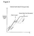
- Figure 4 is a current profile of a Generation I SEM solenoid read back current being energized at different times during the life of the solenoid.
- Profile 1 is a current profile of a newly manufactured solenoid valve.
- Profiles 2-3 are current profiles obtained later in the life of the solenoid valve. In Profile 2, the timing of the current dip is delayed. In Profile 3, the duration of the dip is extended.
- Profiles 2-3 correspond to degraded valve and/or solenoid operations, possibly due to seat wear, debris build-up or other valve and/or solenoid failure mechanisms. Profiles 2-3 are illustrative only. Any manner of change in current profiles may be observed over the life of the valve. For example, the current value at the beginning of the dip may higher or lower as the valve degrades.
- FIG 5 is a current profile of a Generation I solenoid being de-energized at different times during the life of the solenoid.
- Profile 1 is a current profile of a newly manufactured solenoid valve.
- Profiles 2-3 are current profiles obtained later in the life of the solenoid valve. In Profile 2, the timing of the current dip is delayed. In Profile 3, the duration of the dip is extended.
- Profiles 2-3 correspond to degraded valve and/or solenoid operations, possibly due to seat wear, debris build-up or other valve and/or solenoid failure mechanisms.
- Profiles 2-3 are illustrative only. Any manner of change in current profiles may be observed over the life of the valve. For example, the current value at the beginning of the dip may higher or lower as the valve degrades.
- Figure 6 is a current profile of a Generation II solenoid being energized and de-energized at different times during the life of the solenoid.
- Profile 1 is a current profile of a newly manufactured solenoid valve.
- Profiles 2-3 are current profiles obtained later in the life of the solenoid valve. In Profile 2, the timing of both current dips is delayed. In Profile 3, the duration of the dips is extended.
- Profiles 2-3 correspond to degraded valve and/or solenoid operations, possibly due to seat wear, debris build-up or other valve and/or solenoid failure mechanisms.
- Profiles 2-3 are illustrative only. Any manner of change in current profiles may be observed over the life of the valve.
- the current values at the beginning of the dips may higher or lower as the valve degrades.
- Figure 6 identifies various voltage and amperage values. However, these values are illustrative only, as the values may vary according to type of solenoid or age/condition of the solenoid.
- solenoid valves In deep well BOPs, there may be dozens of solenoid valve that may be operated and tested remotely (i.e., from the well platform). In one embodiment, there may be ninety-six (96) solenoid valves. To check the current profile of each of these solenoid valves, the conventional art remote monitor is limited to testing each valve manually through a control panel. Experience has shown that this takes too much time, particularly in crisis situations. To provide a rapid and accurate assessment of a plurality of solenoid valves in a deployed (e.g., submerged and installed) BOP, in one embodiment of the present invention, there is a control device on the well platform that is electrically connected to the plurality of solenoid valves on the BOP.
- a control device on the well platform that is electrically connected to the plurality of solenoid valves on the BOP.
- the control device includes a processor that is connected to a memory.
- the memory stores one or more current profiles for each solenoid valve. These stored current profiles may include a manufacturer's provided profile for the specific solenoid valve or for a class of related solenoid valves, a pre-installation measured profile, and/or one or more profiles captured while the solenoid valve is installed in a submerged BOP.
- the control device is accessed via a control panel (e.g., user interface displayed on a computer) located on platform.
- the control panel is configured to allow an operator to a) select one or more of the plurality of solenoid valves for testing; b) schedule the testing, including establishing a test cycle or schedule; and c) select one or more output modes (including a printed report, a visual alarm or indication, an audio alarm or indication, or a wired or wireless transmission to a remote location.)
- the control panel also is configured to allow an operator to set alarm thresholds for the current profile of one or more solenoid valves.
- the control unit obtains a current profile of the one or more solenoid valves, and compares the obtained profile to one or more of the stored current profiles and/or to the established thresholds.
- changes may be detected visually or automatically based on predetermined threshold criteria.
- the threshold criteria may include the timing or duration of a current dip while energizing and/or de-energizing the solenoid.
- Pattern recognition software may be used to identify a defective or failed solenoid valve.
- the detected changes may be used by a technician or by the computing device (e.g., with a change detection program) to identify solenoid valves that are candidates for replacement prior to actual valve failure.
- the detected changes also may be used by a technician or by the computing device to predict an end-of-life of the corresponding solenoid valve(s). This prediction may be based solely on changes to the current profile or may be combined with historic or predicted valve duty cycles.
- the comparison may result in one or more alarms, including a visual alarm, an audible alarm and a wired or wireless transmission to a remote location.
- alarms including a visual alarm, an audible alarm and a wired or wireless transmission to a remote location.
- the control panel displays a list of valves, grouped by valve identifier or valve function or another characteristic.
- the control panel displays a schematic of valves.
- the control panel is configured to allow the operator to select pre-defined groups of valves or to create groups of valves for testing.
- the control panel is also configured to allow the operator to select all valves and/or to deselect valves individually or by group.
- the control panel allows the operator to initiate testing through an immediate user action, and allows the operator to schedule testing of individual valves or groups of valves. The schedule may or may not include repeated testing on a schedule, or repeated testing if a test results is determined to suggest an existing or imminent valve failure or malfunction.
- control panel may be installed on the platform or the vessel that controls the BOP.
- control panel may be installed remotely from the platform and wirelessly connected to a companion device on the platform.
- the control panel may be a display on a special purpose device, or may be a display on a personal computer or related device (e.g., tablet computer, smart phone, etc.)
- control device discussed above may also be used for testing other devices on the BOP.
- Two examples of such a device are a flow meter and a pressure transducer, as discussed below.
- a flow meter is a device that is used to measure either the velocity of a fluid or gas, the volumetric flow of the fluid or gas, or the mass flow of the fluid or gas.
- the petroleum industry typically employs a variety of flow meters (e.g., turbine and ultrasonic meters) to measure flow rate and other fluid/gas characteristics. The accuracy of such meters generally depends on the continuity and stability of the axial fluid velocity profiles to which they are subjected. Spatially discontinuous profiles or profiles that vary widely in time lead to unpredictable and hence unacceptable variations in the calibrations of such meters.
- a BOP may include many flow meters.
- a control device on the well platform that is electrically connected to the plurality of flow meters on the BOP.
- the control device includes a processor that is connected to a memory.
- the memory stores one or more flow profiles for each flow meter. These stored flow profiles may include a manufacturer's provided profile for the specific flow meter or for a class of related flow meter, a pre-installation measured profile, and/or one or more profiles captured while the flow meter is installed in a submerged BOP.
- the control device is accessed via a control panel located on platform.
- the control panel is configured to allow an operator to a) select one or more of the plurality of flow meter for testing; b) schedule the testing, including establishing a test cycle or schedule; and c) select one or more output modes (including a printed report, a visual alarm or indication, an audio alarm or indication, or a wired or wireless transmission to a remote location.)
- the control panel also is configured to allow an operator to set alarm thresholds for the flow profile of one or more flow meter.
- the control unit obtains a flow profile of the one or more flow meter, and compares the obtained profile to one or more of the stored flow profiles and/or to the established thresholds. This comparison may result in an alarm and/or is output for further analysis.
- a BOP may include many pressure transducers.
- a control device on the well platform that is electrically connected to the plurality of pressure transducers on the BOP.
- the control device includes a processor that is connected to a memory.
- the memory stores one or more pressure profiles for each pressure transducer. These stored pressure profiles may include a manufacturer's provided profile for the specific pressure transducer or for a class of related pressure transducer, a pre-installation measured profile, and/or one or more profiles captured while the pressure transducer is installed in a submerged BOP.
- the control device is accessed via a control panel located on platform.
- the control panel is configured to allow an operator to a) select one or more of the plurality of pressure transducer for testing; b) schedule the testing, including establishing a test cycle or schedule; and c) select one or more output modes (including a printed report, a visual alarm or indication, an audio alarm or indication, or a wired or wireless transmission to a remote location.)
- the control panel also is configured to allow an operator to set alarm thresholds for the pressure profile of one or more pressure transducer.
- the control unit obtains a pressure profile of the one or more pressure transducer, and compares the obtained profile to one or more of the stored pressure profiles and/or to the established thresholds. This comparison may result in an alarm and/or is output for further analysis.
- the above-described new current profiles may be obtained while the controller is submerged or while the controller/BOP is on deck for maintenance or repair.
- the above-described comparisons may include comparisons of one or more complete solenoid energize/de-energize cycles, or may include comparisons of just a solenoid energize action or just a solenoid de-energize action.
- current profiles for the plurality of solenoid valves may be compared to corresponding baseline profiles one-by-one, in series.
- current profiles for the plurality of solenoid valves may be compared to corresponding baseline profiles via one or more groups. That is, in one embodiment, all 96 valves may be cycled simultaneously to obtain their corresponding real-world current profiles. These current profiles may then be simultaneously or near-simultaneously compared to corresponding stored current profiles by the computing device, so as to quickly identify which if any solenoid valves have current profiles indicative of actual or imminent failure.
- the above-described serial and parallel diagnostics may be performed based on a user input or in accordance with a schedule. The above-described serial and parallel diagnostics may be automatically repeated for one or more solenoid valves based on a user input or based on a result of the comparison with the corresponding stored current profile.
- testing based on solenoid current profiles may be replaced by or augmented with testing based on fluid use (e.g., gallon count) from flow meters associated with the solenoid valve.
- fluid use e.g., gallon count
- a flow meter on the BOP may be used test functionality with gallon count ranges displayed by the computing device alongside corresponding solenoid firing indications to assist the rig personnel in detecting hydraulic/mechanical leaks in the stack equipment (e.g., annuluses). If the user or computer detects an inappropriate gallon count for a particular sequence of functions being fired, the user or computer can narrow down the problem to a particular set of functions, thus facilitating easier troubleshooting and/or repair/replacement.
- testing based on solenoid current profiles may be replaced by or augmented with testing based on pressures measured by pressure transducers (e.g., comparing measured pressure values to low and high pressure limits) to detect and diagnose any potential issues with the transducer or involved components.
- pressure transducers e.g., comparing measured pressure values to low and high pressure limits
- FIG. 7 is a block diagram of a control system according to an embodiment of the invention.
- the control system includes a control device 1 connected to a deployed BOP 2 via an undersea electrical connection 3.
- the BOP 2 includes at least one of a group of solenoid valve 21, a group of flow meters 22 and a group of transducers 23.
- the control device includes a processor 11, an interface device 12 that connects the processor to the undersea electrical connection 3, a memory 13 that stores one or more BOP device profiles, a wireless communication device 14, and a display panel 15.
- the disclosed exemplary embodiments provide a system and a method for controlling a subsea well in general, and solenoid valves in particular by a control device.
- the method includes receiving or inputting a modeled and/or measured baseline BOP component profile (e.g., a BOP solenoid current profile_ for each of a plurality of BOP components (e.g., for each of a plurality of solenoid valves) (S1001).
- the baseline BOP component is a solenoid valve
- the BOP component profiles include solenoid current profiles that each include at least one of a pull-in current profile and a drop-out current profile.
- the method further includes grouping two or more of the plurality of BOP components into a test group (S1002).
- the method further includes receiving, by the control device, one or more actual BOP component profiles (e.g., actual solenoid current profiles) from the grouped BOP components in the test group (S1003); and analyzing, by the control device, the actual BOP component profile(s) to determine if any of the grouped BOP components is operating out of specified norms, or whether the any of the grouped BOP components has experienced an actual failure or is liable to experience an imminent failure (S1004).
- the analysis may include comparing the measured profile(s) to one or more stored profiles (e.g., a stored baseline profile or a previously obtained actual profile).
- the analysis may include analyzing only a portion of the actual BOP component profiles (e.g., only the solenoid energizing or de-energizing current profiles), or analyzing an entirety of the actual BOP component profiles.
- the analysis may include performing automatic change detection analysis to identify changes in the profiles that are indicative of component wear or failure.
- the analysis may include predicting an end-of-life one or more of the BOP components based the change between the actual BOP component profiles and the one or more stored BOP component profiles.
- the end-of-life analysis may also take into consideration at least one of a historic BOP component duty cycle and a predicted BOP component duty cycle.
- the BOP component may be a solenoid valve, a transducer, a flow meter or another device.
- non-transitory computer readable medium containing instructions configured to cause a computing device to execute the method described above.
Landscapes
- Geology (AREA)
- Life Sciences & Earth Sciences (AREA)
- Engineering & Computer Science (AREA)
- Mining & Mineral Resources (AREA)
- Physics & Mathematics (AREA)
- Geochemistry & Mineralogy (AREA)
- Fluid Mechanics (AREA)
- General Life Sciences & Earth Sciences (AREA)
- Environmental & Geological Engineering (AREA)
- General Physics & Mathematics (AREA)
- Testing Of Devices, Machine Parts, Or Other Structures Thereof (AREA)
- Testing Or Calibration Of Command Recording Devices (AREA)
- Testing And Monitoring For Control Systems (AREA)
- Geophysics And Detection Of Objects (AREA)
- Flow Control (AREA)
- Magnetically Actuated Valves (AREA)
- Arrangements For Transmission Of Measured Signals (AREA)
Applications Claiming Priority (1)
| Application Number | Priority Date | Filing Date | Title |
|---|---|---|---|
| US13/221,065 US20130054034A1 (en) | 2011-08-30 | 2011-08-30 | Method, device and system for monitoring subsea components |
Publications (2)
| Publication Number | Publication Date |
|---|---|
| EP2565366A2 true EP2565366A2 (de) | 2013-03-06 |
| EP2565366A3 EP2565366A3 (de) | 2017-08-30 |
Family
ID=47225917
Family Applications (1)
| Application Number | Title | Priority Date | Filing Date |
|---|---|---|---|
| EP12181148.3A Withdrawn EP2565366A3 (de) | 2011-08-30 | 2012-08-21 | System, Vorrichtung und Verfahren zur Überwachung von Unterwasserkomponenten |
Country Status (11)
| Country | Link |
|---|---|
| US (1) | US20130054034A1 (de) |
| EP (1) | EP2565366A3 (de) |
| KR (1) | KR20130024841A (de) |
| CN (1) | CN103033696A (de) |
| AR (1) | AR087696A1 (de) |
| AU (1) | AU2012216362A1 (de) |
| BR (1) | BR102012021750A2 (de) |
| CA (1) | CA2787609A1 (de) |
| EA (1) | EA201201066A1 (de) |
| MX (1) | MX2012010045A (de) |
| SG (1) | SG188062A1 (de) |
Cited By (5)
| Publication number | Priority date | Publication date | Assignee | Title |
|---|---|---|---|---|
| WO2015103473A3 (en) * | 2014-01-02 | 2015-10-08 | Hydril USA Distribution LLC | Systems and methods to visualize component health and preventive maintenance needs for subsea control subsystem components |
| WO2016131042A1 (en) | 2015-02-15 | 2016-08-18 | Transocean Innovation Labs Ltd | Bop control systems and related methods |
| WO2016179470A1 (en) * | 2015-05-07 | 2016-11-10 | Hydril USA Distribution LLC | Systems and methods for handling overcurrent and undercurrent conditions in subsea control subsystem components |
| US9798030B2 (en) | 2013-12-23 | 2017-10-24 | General Electric Company | Subsea equipment acoustic monitoring system |
| EP4065815A4 (de) * | 2019-11-25 | 2023-12-06 | Cold Bore Technology Inc. | Automatische detektion von steck- und lochkomplementen, bohrlochköpfen und bohrlochstandbetriebsstatus |
Families Citing this family (26)
| Publication number | Priority date | Publication date | Assignee | Title |
|---|---|---|---|---|
| KR101456781B1 (ko) * | 2013-04-25 | 2014-11-12 | (주)부품디비 | 해양 굴착, 시추 장비의 예지보전을 위한 학습적 고장유형 관리 장치 및 방법 |
| CN105593857A (zh) * | 2013-11-18 | 2016-05-18 | 兰德马克绘图国际公司 | 无立管条件下的预测振动模型 |
| KR101707506B1 (ko) * | 2014-04-14 | 2017-02-16 | 대우조선해양 주식회사 | 시추선의 장비 시뮬레이션 및 장비 제어 장치 |
| MX2017004132A (es) * | 2014-09-30 | 2018-02-01 | Hydril Usa Distrib Llc | Sistema de clasificacion de niveles de integridad de seguridad (sil) para control de preventores de reventones submarinos. |
| US10876369B2 (en) | 2014-09-30 | 2020-12-29 | Hydril USA Distribution LLC | High pressure blowout preventer system |
| US10048673B2 (en) | 2014-10-17 | 2018-08-14 | Hydril Usa Distribution, Llc | High pressure blowout preventer system |
| US10196871B2 (en) | 2014-09-30 | 2019-02-05 | Hydril USA Distribution LLC | Sil rated system for blowout preventer control |
| US9989975B2 (en) | 2014-11-11 | 2018-06-05 | Hydril Usa Distribution, Llc | Flow isolation for blowout preventer hydraulic control systems |
| US20160131692A1 (en) * | 2014-11-12 | 2016-05-12 | Cameron International Corporation | Cable Monitoring Apparatus |
| US9759018B2 (en) | 2014-12-12 | 2017-09-12 | Hydril USA Distribution LLC | System and method of alignment for hydraulic coupling |
| US20160179106A1 (en) * | 2014-12-17 | 2016-06-23 | Hydril USA Distribution LLC | Pressure regulator for fluid hammer reduction |
| US9528340B2 (en) | 2014-12-17 | 2016-12-27 | Hydrill USA Distribution LLC | Solenoid valve housings for blowout preventer |
| KR102480546B1 (ko) | 2014-12-17 | 2022-12-22 | 하이드릴 유에스에이 디스트리뷰션 엘엘씨 | 제어 포드, 보조 해저 시스템, 표면 제어부 간의 인터페이스를 위한 전력 및 통신 허브 |
| KR101518720B1 (ko) * | 2015-02-15 | 2015-05-08 | (주)부품디비 | 해양자원 생산장비의 예지보전을 위한 고장유형관리 장치 및 방법 |
| US10107712B2 (en) * | 2015-04-07 | 2018-10-23 | HilFlo, LLC | Automated blowout preventer control and testing system |
| US9828824B2 (en) * | 2015-05-01 | 2017-11-28 | Hydril Usa Distribution, Llc | Hydraulic re-configurable and subsea repairable control system for deepwater blow-out preventers |
| US10995589B2 (en) * | 2015-10-02 | 2021-05-04 | Halliburton Energy Services, Inc. | Setting valve configurations in a manifold system |
| CN105675094B (zh) * | 2015-12-30 | 2018-09-25 | 中国船舶重工集团公司七五〇试验场 | 一种深度传感器自动校准系统及校准方法 |
| BR112018068837B1 (pt) * | 2016-03-18 | 2022-11-16 | National Oilwell Varco, L.P. | Método e sistema para perfurar um poço |
| US10619760B2 (en) * | 2016-10-24 | 2020-04-14 | Fisher Controls International Llc | Time-series analytics for control valve health assessment |
| US10530748B2 (en) | 2016-10-24 | 2020-01-07 | Fisher-Rosemount Systems, Inc. | Publishing data across a data diode for secured process control communications |
| NO343693B1 (en) * | 2017-06-14 | 2019-05-13 | Fmc Kongsberg Subsea As | Electric power and communication module |
| US10900347B2 (en) | 2018-03-01 | 2021-01-26 | Cameron International Corporation | BOP elastomer health monitoring |
| CN108729900B (zh) * | 2018-04-26 | 2021-11-16 | 中国科学院电工研究所 | 一种自供电水下废弃油井监测系统及监测方法 |
| KR102159676B1 (ko) * | 2020-07-01 | 2020-09-25 | 주식회사 유아이티 | 시추 제어 시스템의 입력장치 및 이의 동작 방법 |
| CN113959499B (zh) * | 2021-11-03 | 2022-06-14 | 中国海洋大学 | 深海采矿生态环境原位长期自动监测站及其评价方法 |
Family Cites Families (30)
| Publication number | Priority date | Publication date | Assignee | Title |
|---|---|---|---|---|
| US3740739A (en) * | 1971-11-30 | 1973-06-19 | Dresser Ind | Well monitoring and warning system |
| US4617960A (en) * | 1985-05-03 | 1986-10-21 | Develco, Inc. | Verification of a surface controlled subsurface actuating device |
| US5732776A (en) * | 1995-02-09 | 1998-03-31 | Baker Hughes Incorporated | Downhole production well control system and method |
| US5687098A (en) * | 1995-10-30 | 1997-11-11 | Fisher Controls International, Inc. | Device data acquisition |
| US6111514A (en) * | 1996-12-18 | 2000-08-29 | Kelsey-Hayes Company | Solenoid fail-safe using current feedback as a diagnostic input |
| US6199629B1 (en) * | 1997-09-24 | 2001-03-13 | Baker Hughes Incorporated | Computer controlled downhole safety valve system |
| US6192321B1 (en) * | 1997-09-29 | 2001-02-20 | Fisher Controls International, Inc. | Method of and apparatus for deterministically obtaining measurements |
| US6307376B1 (en) * | 1998-12-23 | 2001-10-23 | Eaton Corporation | Fault detection system and method for solenoid controlled actuators of a transmission system |
| US6216784B1 (en) * | 1999-07-29 | 2001-04-17 | Halliburton Energy Services, Inc. | Subsurface electro-hydraulic power unit |
| US6343649B1 (en) * | 1999-09-07 | 2002-02-05 | Halliburton Energy Services, Inc. | Methods and associated apparatus for downhole data retrieval, monitoring and tool actuation |
| US6422315B1 (en) * | 1999-09-14 | 2002-07-23 | Quenton Wayne Dean | Subsea drilling operations |
| US6488093B2 (en) * | 2000-08-11 | 2002-12-03 | Exxonmobil Upstream Research Company | Deep water intervention system |
| US6655405B2 (en) * | 2001-01-31 | 2003-12-02 | Cilmore Valve Co. | BOP operating system with quick dump valve |
| EP1270870B1 (de) * | 2001-06-22 | 2006-08-16 | Cooper Cameron Corporation | Testvorrichtung für Ausbruchpreventer |
| CN2698978Y (zh) * | 2004-05-26 | 2005-05-11 | 中国石化集团胜利石油管理局钻井工艺研究院 | 一种欠平衡钻井实时监测控制装置 |
| US20060033638A1 (en) * | 2004-08-10 | 2006-02-16 | Hall David R | Apparatus for Responding to an Anomalous Change in Downhole Pressure |
| US8517113B2 (en) * | 2004-12-21 | 2013-08-27 | Schlumberger Technology Corporation | Remotely actuating a valve |
| US7539548B2 (en) * | 2005-02-24 | 2009-05-26 | Sara Services & Engineers (Pvt) Ltd. | Smart-control PLC based touch screen driven remote control panel for BOP control unit |
| US8036760B2 (en) * | 2005-10-04 | 2011-10-11 | Fisher-Rosemount Systems, Inc. | Method and apparatus for intelligent control and monitoring in a process control system |
| US8159365B2 (en) * | 2008-04-16 | 2012-04-17 | Hydril Usa Manufacturing Llc | Distributed databases for a well control drilling system |
| US8347967B2 (en) * | 2008-04-18 | 2013-01-08 | Sclumberger Technology Corporation | Subsea tree safety control system |
| US8542006B2 (en) * | 2008-12-16 | 2013-09-24 | Hydril USA Manfacturing LLC | Movement detection circuit of solenoid shear seal valve on subsea pressure control system and method of detecting movement of solenoid actuator |
| US8490705B2 (en) * | 2009-10-28 | 2013-07-23 | Diamond Offshore Drilling, Inc. | Hydraulic control system monitoring apparatus and method |
| EA022742B1 (ru) * | 2010-03-05 | 2016-02-29 | Сейфкик Америкас Ллк | Система и способ безопасных операций управления скважиной |
| US9057751B2 (en) * | 2010-04-30 | 2015-06-16 | Schlumberger Technology Corporation | Ground fault detection for an electrical subsea control system |
| US8464797B2 (en) * | 2010-04-30 | 2013-06-18 | Hydril Usa Manufacturing Llc | Subsea control module with removable section and method |
| US8393399B2 (en) * | 2010-11-30 | 2013-03-12 | Hydril Usa Manufacturing Llc | Blowout preventer with intervention, workover control system functionality and method |
| US8511388B2 (en) * | 2010-12-16 | 2013-08-20 | Hydril Usa Manufacturing Llc | Devices and methods for transmitting EDS back-up signals to subsea pods |
| US8781743B2 (en) * | 2011-01-27 | 2014-07-15 | Bp Corporation North America Inc. | Monitoring the health of a blowout preventer |
| US20130050480A1 (en) * | 2011-08-30 | 2013-02-28 | Hydril Usa Manufacturing Llc | Emergency disconnect sequence video sharing |
-
2011
- 2011-08-30 US US13/221,065 patent/US20130054034A1/en not_active Abandoned
-
2012
- 2012-08-21 EP EP12181148.3A patent/EP2565366A3/de not_active Withdrawn
- 2012-08-22 AU AU2012216362A patent/AU2012216362A1/en not_active Abandoned
- 2012-08-22 SG SG2012062279A patent/SG188062A1/en unknown
- 2012-08-23 CA CA2787609A patent/CA2787609A1/en not_active Abandoned
- 2012-08-28 AR ARP120103168A patent/AR087696A1/es unknown
- 2012-08-29 BR BR102012021750-3A patent/BR102012021750A2/pt not_active IP Right Cessation
- 2012-08-29 KR KR1020120095022A patent/KR20130024841A/ko not_active Application Discontinuation
- 2012-08-29 EA EA201201066A patent/EA201201066A1/ru unknown
- 2012-08-30 MX MX2012010045A patent/MX2012010045A/es not_active Application Discontinuation
- 2012-08-30 CN CN2012103142518A patent/CN103033696A/zh active Pending
Non-Patent Citations (1)
| Title |
|---|
| None |
Cited By (9)
| Publication number | Priority date | Publication date | Assignee | Title |
|---|---|---|---|---|
| US9798030B2 (en) | 2013-12-23 | 2017-10-24 | General Electric Company | Subsea equipment acoustic monitoring system |
| US10451760B2 (en) | 2013-12-23 | 2019-10-22 | General Electric Company | Subsea equipment acoustic monitoring system |
| WO2015103473A3 (en) * | 2014-01-02 | 2015-10-08 | Hydril USA Distribution LLC | Systems and methods to visualize component health and preventive maintenance needs for subsea control subsystem components |
| WO2016131042A1 (en) | 2015-02-15 | 2016-08-18 | Transocean Innovation Labs Ltd | Bop control systems and related methods |
| EP3256687A4 (de) * | 2015-02-15 | 2019-03-06 | Transocean Innovation Labs Ltd | Bop-kontrollsysteme und zugehörige verfahren |
| US11460835B2 (en) | 2015-02-15 | 2022-10-04 | Transocean Innovation Labs Ltd. | BOP control systems and related methods |
| WO2016179470A1 (en) * | 2015-05-07 | 2016-11-10 | Hydril USA Distribution LLC | Systems and methods for handling overcurrent and undercurrent conditions in subsea control subsystem components |
| US10404052B2 (en) | 2015-05-07 | 2019-09-03 | Hydril Usa Distribution, Llc | Systems and methods for handling overcurrent and undercurrent conditions in subsea control subsystem components |
| EP4065815A4 (de) * | 2019-11-25 | 2023-12-06 | Cold Bore Technology Inc. | Automatische detektion von steck- und lochkomplementen, bohrlochköpfen und bohrlochstandbetriebsstatus |
Also Published As
| Publication number | Publication date |
|---|---|
| BR102012021750A2 (pt) | 2014-05-13 |
| SG188062A1 (en) | 2013-03-28 |
| CA2787609A1 (en) | 2013-02-28 |
| CN103033696A (zh) | 2013-04-10 |
| AR087696A1 (es) | 2014-04-09 |
| MX2012010045A (es) | 2013-03-06 |
| EA201201066A1 (ru) | 2013-04-30 |
| AU2012216362A1 (en) | 2013-03-21 |
| EP2565366A3 (de) | 2017-08-30 |
| US20130054034A1 (en) | 2013-02-28 |
| KR20130024841A (ko) | 2013-03-08 |
Similar Documents
| Publication | Publication Date | Title |
|---|---|---|
| EP2565366A2 (de) | System, Vorrichtung und Verfahren zur Überwachung von Unterwasserkomponenten | |
| US8515880B2 (en) | Condition monitoring of an underwater facility | |
| EP2053289B1 (de) | Überwachung eines Magnets eines Richtungssteuerungsventils | |
| US10968731B2 (en) | System and method for monitoring a blowout preventer | |
| EP2668367B1 (de) | Überwachung der integrität eines ausbruchschiebers | |
| US10012049B2 (en) | Proof testing apparatus and method for reducing the probability of failure on demand of safety rated hydraulic components | |
| EP2466060A2 (de) | Funktionstestsystem und -Verfahren für Schaltung | |
| EP2610427A1 (de) | Vorrichtungen und Verfahren zur Bestimmung des Bohrloch-Influx-Zustandes mit qualitativen Hinweisen | |
| EP2466062A2 (de) | Vorrichtungen und Verfahren zur Übertragung von EDS-Back-Up-Signalen an Unterwasserbehälter | |
| AU2014302262A1 (en) | Subsea landing string with autonomous emergency shut-in and disconnect | |
| US20120051186A1 (en) | Valve condition monitoring | |
| US11840916B2 (en) | System and method for monitoring abandoned subsea wells with wet Christmas tree | |
| EP2469015B2 (de) | Prognose für Bohrlochdaten | |
| US20200182045A1 (en) | Downhole monitoring of hydraulic equipment |
Legal Events
| Date | Code | Title | Description |
|---|---|---|---|
| PUAI | Public reference made under article 153(3) epc to a published international application that has entered the european phase |
Free format text: ORIGINAL CODE: 0009012 |
|
| AK | Designated contracting states |
Kind code of ref document: A2 Designated state(s): AL AT BE BG CH CY CZ DE DK EE ES FI FR GB GR HR HU IE IS IT LI LT LU LV MC MK MT NL NO PL PT RO RS SE SI SK SM TR |
|
| AX | Request for extension of the european patent |
Extension state: BA ME |
|
| PUAL | Search report despatched |
Free format text: ORIGINAL CODE: 0009013 |
|
| AK | Designated contracting states |
Kind code of ref document: A3 Designated state(s): AL AT BE BG CH CY CZ DE DK EE ES FI FR GB GR HR HU IE IS IT LI LT LU LV MC MK MT NL NO PL PT RO RS SE SI SK SM TR |
|
| AX | Request for extension of the european patent |
Extension state: BA ME |
|
| RIC1 | Information provided on ipc code assigned before grant |
Ipc: E21B 33/035 20060101AFI20170725BHEP Ipc: E21B 33/06 20060101ALI20170725BHEP |
|
| STAA | Information on the status of an ep patent application or granted ep patent |
Free format text: STATUS: THE APPLICATION IS DEEMED TO BE WITHDRAWN |
|
| 18D | Application deemed to be withdrawn |
Effective date: 20180301 |