EP2565052A2 - Bicycle front wheel hub with torque tube - Google Patents
Bicycle front wheel hub with torque tube Download PDFInfo
- Publication number
- EP2565052A2 EP2565052A2 EP12006121A EP12006121A EP2565052A2 EP 2565052 A2 EP2565052 A2 EP 2565052A2 EP 12006121 A EP12006121 A EP 12006121A EP 12006121 A EP12006121 A EP 12006121A EP 2565052 A2 EP2565052 A2 EP 2565052A2
- Authority
- EP
- European Patent Office
- Prior art keywords
- hub
- torque tube
- mating element
- fork
- bicycle
- Prior art date
- Legal status (The legal status is an assumption and is not a legal conclusion. Google has not performed a legal analysis and makes no representation as to the accuracy of the status listed.)
- Withdrawn
Links
- 230000013011 mating Effects 0.000 claims abstract description 47
- 238000010276 construction Methods 0.000 claims description 5
- 230000008901 benefit Effects 0.000 description 3
- 230000006870 function Effects 0.000 description 3
- 230000007246 mechanism Effects 0.000 description 3
- 239000000725 suspension Substances 0.000 description 3
- 239000000428 dust Substances 0.000 description 2
- 230000014759 maintenance of location Effects 0.000 description 2
- 238000000034 method Methods 0.000 description 2
- 238000004026 adhesive bonding Methods 0.000 description 1
- 238000011109 contamination Methods 0.000 description 1
- 230000008878 coupling Effects 0.000 description 1
- 238000010168 coupling process Methods 0.000 description 1
- 238000005859 coupling reaction Methods 0.000 description 1
- 230000001627 detrimental effect Effects 0.000 description 1
- 230000000694 effects Effects 0.000 description 1
- 230000002708 enhancing effect Effects 0.000 description 1
- 238000012423 maintenance Methods 0.000 description 1
- 125000006850 spacer group Chemical group 0.000 description 1
- 238000003466 welding Methods 0.000 description 1
Images

Classifications
-
- B—PERFORMING OPERATIONS; TRANSPORTING
- B60—VEHICLES IN GENERAL
- B60B—VEHICLE WHEELS; CASTORS; AXLES FOR WHEELS OR CASTORS; INCREASING WHEEL ADHESION
- B60B27/00—Hubs
- B60B27/02—Hubs adapted to be rotatably arranged on axle
- B60B27/023—Hubs adapted to be rotatably arranged on axle specially adapted for bicycles
- B60B27/026—Hubs adapted to be rotatably arranged on axle specially adapted for bicycles comprising quick release devices
-
- B—PERFORMING OPERATIONS; TRANSPORTING
- B60—VEHICLES IN GENERAL
- B60B—VEHICLE WHEELS; CASTORS; AXLES FOR WHEELS OR CASTORS; INCREASING WHEEL ADHESION
- B60B27/00—Hubs
- B60B27/0047—Hubs characterised by functional integration of other elements
- B60B27/0052—Hubs characterised by functional integration of other elements the element being a brake disc
-
- B—PERFORMING OPERATIONS; TRANSPORTING
- B60—VEHICLES IN GENERAL
- B60B—VEHICLE WHEELS; CASTORS; AXLES FOR WHEELS OR CASTORS; INCREASING WHEEL ADHESION
- B60B27/00—Hubs
- B60B27/02—Hubs adapted to be rotatably arranged on axle
- B60B27/023—Hubs adapted to be rotatably arranged on axle specially adapted for bicycles
-
- B—PERFORMING OPERATIONS; TRANSPORTING
- B62—LAND VEHICLES FOR TRAVELLING OTHERWISE THAN ON RAILS
- B62K—CYCLES; CYCLE FRAMES; CYCLE STEERING DEVICES; RIDER-OPERATED TERMINAL CONTROLS SPECIALLY ADAPTED FOR CYCLES; CYCLE AXLE SUSPENSIONS; CYCLE SIDE-CARS, FORECARS, OR THE LIKE
- B62K25/00—Axle suspensions
- B62K25/02—Axle suspensions for mounting axles rigidly on cycle frame or fork, e.g. adjustably
-
- B—PERFORMING OPERATIONS; TRANSPORTING
- B60—VEHICLES IN GENERAL
- B60B—VEHICLE WHEELS; CASTORS; AXLES FOR WHEELS OR CASTORS; INCREASING WHEEL ADHESION
- B60B27/00—Hubs
-
- B—PERFORMING OPERATIONS; TRANSPORTING
- B60—VEHICLES IN GENERAL
- B60B—VEHICLE WHEELS; CASTORS; AXLES FOR WHEELS OR CASTORS; INCREASING WHEEL ADHESION
- B60B2900/00—Purpose of invention
- B60B2900/20—Avoidance of
- B60B2900/212—Damage
-
- B—PERFORMING OPERATIONS; TRANSPORTING
- B60—VEHICLES IN GENERAL
- B60B—VEHICLE WHEELS; CASTORS; AXLES FOR WHEELS OR CASTORS; INCREASING WHEEL ADHESION
- B60B2900/00—Purpose of invention
- B60B2900/30—Increase in
- B60B2900/311—Rigidity or stiffness
-
- B—PERFORMING OPERATIONS; TRANSPORTING
- B60—VEHICLES IN GENERAL
- B60Y—INDEXING SCHEME RELATING TO ASPECTS CROSS-CUTTING VEHICLE TECHNOLOGY
- B60Y2200/00—Type of vehicle
- B60Y2200/10—Road Vehicles
- B60Y2200/13—Bicycles; Tricycles
- B60Y2200/132—All terrain bikes
-
- B—PERFORMING OPERATIONS; TRANSPORTING
- B62—LAND VEHICLES FOR TRAVELLING OTHERWISE THAN ON RAILS
- B62K—CYCLES; CYCLE FRAMES; CYCLE STEERING DEVICES; RIDER-OPERATED TERMINAL CONTROLS SPECIALLY ADAPTED FOR CYCLES; CYCLE AXLE SUSPENSIONS; CYCLE SIDE-CARS, FORECARS, OR THE LIKE
- B62K25/00—Axle suspensions
- B62K25/02—Axle suspensions for mounting axles rigidly on cycle frame or fork, e.g. adjustably
- B62K2025/025—Hinged axle clamps
Definitions
- This invention relates to bicycle hubs, and more particularly, to a bicycle front wheel hub.
- the invention relates to a bicycle front wheel hub with a torque tube.
- a typical bicycle frame set has a bicycle fork for mounting a wheel to the bicycle.
- a typical fork has a pair of spaced apart fork legs (or at least one fork leg), each leg having a dropout at a terminal end.
- the dropouts have inner sides (facing each other), outer sides opposite the inner sides, and an elongated aperture formed therein to form a slot to receive a hub for a connection of the wheel to the fork.
- the hub of the bicycle wheel is mounted on the skewer, and thus a wheel may be mounted and fastened on the bicycle frame by inserting and fastening the skewer into the slot and on the dropout.
- Disc brakes have typically been used in off-road and racing applications, both downhill and cross-country. Disc brakes include a brake disc mounted on the hub adjacent the center of the wheel and a brake pad mounted adjacent the brake disc. The brake pad engages the brake disc to slow down rotation of the bicycle wheel.
- Bicycles with suspension forks, and in particular telescopic upside down (USD) forks (with stanchions at the bottom) are particularly prone to suffering twisting forces due to steering, braking and operation off-road, for example. This is due to the fact that the USD fork stanchions are only connected through the hub.
- Typical bicycle hubs have internal rotational connections between the left mounting surface and the right mounting surface which can allow both fork legs of a USD fork to flex and rotate independently - a tendency if minimized improves the functioning of the fork.
- the invention includes a hub for a bicycle that increases the torsion rigidity of an attached front fork.
- the hub has a tubular member that is essentially one continuous component that connects one fork mounting leg to the other fork mounting leg.
- the connection created by assembling the hub and fork according to the invention transfers torque, for example created by rider induced handlebar torque, from one fork leg to the other fork leg, thus increasing overall bicycle performance and enhancing rider control.
- the continuous hub component which may be referred to as a torque tube, connects the fork legs so that when one fork is twisted, that fork leg's torque is transferred to the opposing fork leg, thereby creating a torsionally stiffer fork (and hub assembly) than with a conventional hub.
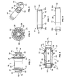
- FIGS. 1-8 show a hub 18 for a bicycle front wheel.
- the hub 18 generally includes a hub body 20 and a torque tube 38 positioned in the hub body.
- the hub 18 includes a first hub bearing 30 and a second hub bearing 34 spaced from the first hub bearing.
- the hub bearings 30, 34 are disposed between the hub body 20 and torque tube 38 to permit the hub body to rotate about the torque tube 38. It will be understood that more than two bearings can be used.
- the hub body 20 includes a central shell part 21 located generally between a pair of spaced spoke flanges including a first flange 22 and a second flange 24, each flange including a plurality of spoke holes 26 or some means of capturing the ends of or otherwise providing for the retention of spoke members of a wheel.
- the central shell part 21 can be cylindrical or other suitable shapes.
- the hub body 20 includes a brake rotor mounting flange 28 with a number of brake rotor mounting holes 29 for mounting a brake rotor thereto.
- the brake rotor mounting flange 28 is shown positioned outboard of the second spoke flange 24.
- First hub bearing 30 and second hub bearing 34 are positioned inside the hub body 20 at or near respective ends 31, 33 of the central shell part 21.
- One of dust seals 32, 36 are provided at or near respective outboard sides of each of the bearings 30, 34 and essentially seal the hub bearings (and the interior of the hub body 20) to contamination and also may function to retain the bearings in place.
- the torque tube 38 is preferably a generally cylindrical element and is sized and shaped to be received within the hub body 20.
- the torque tube 38 includes a first shoulder 40 spaced inboard from a first end 41 of the torque tube against which the first bearing 30 rests and a second shoulder 42 spaced inboard from a second end 43 of the torque tube against which the second bearing 34 rests.
- the shoulders 40, 42 of the torque tube cooperate with the dust seals 32, 36 and counter-bores (shown in more detail below) formed in the interior of the hub or a clip member in a groove to position the bearings 30, 34, which in the example shown are sealed, cartridge-type bearings and thus permit the hub shell to rotate about the torque tube.
- the torque tube 38 may be a single piece construction or, as is shown, a multi-part construction.
- the torque tube 38 of the illustrated embodiment includes a first part 38a, which is generally an elongated cylinder, and a second part 38b, which is generally in the form of a cap that fits to the first part.
- the first and second parts 38a, 38b can be fitted by interference fit, welding, gluing, threaded engagement or any suitable joining technique.
- the torque tube 38 may include at least one boss 50 at each end thereof.
- three bosses 50 are positioned about an annular end face 52 located at each of the torque tube ends.
- the bosses 50 are shaped and sized to cooperatively fit to matching features 54 of first mating element 44 and second mating element 46.
- the mating elements 44, 46 are respectively positioned on opposite ends of the torque tube 38 ( FIG. 2 ).
- the mating elements 44, 46 are preferably ring shaped parts.
- the interior of each ring shaped mating element 44, 46 can include matching features 54 in the form of relieved sections shaped and sized to each receive one of the at least one bosses 50.
- the mating elements 44, 46 are preferably held to the ends of the torque tube 38 with a plurality of fasteners 48, e.g. bolts. It will be understood that the mating elements 44, 46could be non-ring shapes.
- the at least one boss 50 and matching features 54 could take a number of cooperative shapes having the purpose of releasably fixing the mating elements 44, 46 to the ends of the torque tube 38.
- the mating elements 44, 46 could be formed as or attached to the torque tube 38 by a splined engagement, at least one post, a threaded engagement, or a toothed engagement or any suitable fastening technique.
- the mating elements 44, 46 are removable to permit access to the bearings, for example, i.e., for maintenance of the hub.
- the mating element 46 resembles a ring gear with an anti-rotation hub feature 56, wherein the anti-rotation hub feature is, for example, a set of teeth 60 located on the outer-facing surface 58 of the ring.
- the mating elements 44, 46 are oriented in a manner so that the anti-rotation hub features 56 at each end of the assembled torque tube 38 are aligned so as to properly engage cooperating mating features in a bicycle fork. It is preferred that the engagement of the bosses 50 and matching features 54 assist in the alignment.
- the outer diameter OD (D1) of the mating elements 44, 46 is preferably greater than the diameter (D2) of the end of the torque tube in order to facilitate retention of the seals 32, 36 and bearings 30, 34 in place on the torque tube 38. It will be understood that D1 could be the same as D2, or even smaller.
- the anti-rotation hub feature 56 of each of the mating elements 44, 46 is shown as a plurality of teeth 60, but could be any number of teeth, such as one or more tooth or tooth-like element.
- the illustrated teeth are triangular in shape, but other shapes capable of preventing or reducing rotation are contemplated by the invention such as square, ramp, truncated, domed, and the like.
- the hub 18 of the invention may employ a skewer or other conventional mechanism to attach the hub to a bicycle fork as will be described in more detail in FIG. 9 .
- the interior of the hub body 20 includes a first counter bore 62 located near the first end 31 of the hub body and a second counter bore 64 near the second end 33 of the hub body.
- the counterbores 62, 64 are sized and shaped to receive the outer diameter of the bearings 30, 34.
- the seals 32, 36 are positioned outboard of respective bearings 30, 34 and function to hold the bearings in position in the counter bores 62, 64 and on the shoulders 40, 42 of the torque tube 38.
- Other mechanisms of retaining the bearings such as the use of clips or retaining rings may be employed, as is well known.
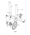
- FIG. 9 a hub 20 according to the invention is shown, for illustrative purposes, in use with a USD suspension fork 70. It will be understood that other types of forks would benefit from the hub 20, and these are also contemplated by the invention. It is believed that a USD fork would benefit the most from a hub according to the invention.
- the fork 70 includes first and second stanchions 72, 74.
- Each stanchion 72, 74 includes a respective fork end member 76, 78 with a hub engaging part 80, 82, which is similar to a fork dropout in position and function by engaging with the hub 18.
- Each hub engaging part 80, 82 includes a respective inner facing surface 84, 86 with an anti-rotation fork feature 88.
- the anti-rotation fork features 88 cooperatively match and mate with or couple with the anti-rotation hub features 56.
- the anti-rotation hub features 56 are in the form of triangular teeth
- the anti-rotation fork features 88 are also in the form of triangular teeth that mesh with the teeth of the hub features to form a coupling of the features capable of transferring torque thereacross.
- a number of configurations could comprise the cooperative engagement between the fork and hub wherein the configuration supplies an effective amount of torque transfer from one fork leg (for example, leg 72) through the hub 18 and to the other fork leg (for example, leg 74). Since the mating elements 44, 46 are rotationally fixed to the torque tube 38 and the torque tube does not rotate, the torque tube resists twisting when one or both of the fork legs 72, 74 are exposed to a twisting force.
- the hub 18 and fork 70 are shown, for purposes of providing environment, with a brake rotor 90, which is attachable to the brake rotor mounting flange 28 of the hub and a brake caliper 92 which is attachable to the fork stanchion 78.
- the hub 18 is attached to the fork 70, in the illustrated example, by way of a thru axle skewer 94, which may be inserted through the second hub engaging member 82, through the interior of the torque tube 38, and through the first hub engaging member 80.
- the thru axle skewer 94 is completed and secured in place by a lock nut assembly 96.
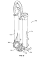
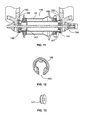
- FIGS. 10-13 show a fork 170 and hub 118 according to an embodiment of the invention, where the fork has a pair of fork legs 172, 174; each with a respective conventional drop out 180, 182, and a conventional skewer 194 for holding the hub in the fork dropouts.
- the hub body 20 of hub 118 may be the same structurally as that of the previous embodiment.
- the fork dropouts 180, 182 each include an anti-rotation fork feature 188 in the form of an interrupted ring with a slot 145.
- the anti-rotation fork feature 188 can be attachable to the dropouts 180, 182 as shown, or formed as part of the dropouts.
- the slot 145 is oriented on the dropout so as to receive and remove the hub 118 and skewer 194.
- the shape of the anti-rotation fork feature 188 mates and cooperates with the first and second mating elements 144, 146 to transfer torque from one of the fork legs to the other of the fork legs 172, 174 and thus cause the combined fork and hub assembly to be torsionally stiff.
- the hub 118 may include a pair of adapters 147, one at each end of the hub, which are sized, typically with a 5mm opening, to locate a skewer concentrically in the hub.
Landscapes
- Engineering & Computer Science (AREA)
- Mechanical Engineering (AREA)
- Axle Suspensions And Sidecars For Cycles (AREA)
- Shafts, Cranks, Connecting Bars, And Related Bearings (AREA)
Abstract
Description
- This invention relates to bicycle hubs, and more particularly, to a bicycle front wheel hub. In particular, the invention relates to a bicycle front wheel hub with a torque tube.
- A typical bicycle frame set has a bicycle fork for mounting a wheel to the bicycle. A typical fork has a pair of spaced apart fork legs (or at least one fork leg), each leg having a dropout at a terminal end. The dropouts have inner sides (facing each other), outer sides opposite the inner sides, and an elongated aperture formed therein to form a slot to receive a hub for a connection of the wheel to the fork. The hub of the bicycle wheel is mounted on the skewer, and thus a wheel may be mounted and fastened on the bicycle frame by inserting and fastening the skewer into the slot and on the dropout.
- Significant torsion forces can be applied to the wheel and thus the fork, such as during braking, steering and from forces encountered by rough terrain, for example. One particular example of such force is generated when braking forces are applied to the wheel by a bicycle disc brake. Disc brakes have typically been used in off-road and racing applications, both downhill and cross-country. Disc brakes include a brake disc mounted on the hub adjacent the center of the wheel and a brake pad mounted adjacent the brake disc. The brake pad engages the brake disc to slow down rotation of the bicycle wheel.
- Due to the forces that arise when the disc brake is applied to slow rotation of the bicycle wheel, forces generated by disc brakes can induce a twisting torque which can be detrimental to steering precision.
- Bicycles with suspension forks, and in particular telescopic upside down (USD) forks (with stanchions at the bottom) are particularly prone to suffering twisting forces due to steering, braking and operation off-road, for example. This is due to the fact that the USD fork stanchions are only connected through the hub. Typical bicycle hubs have internal rotational connections between the left mounting surface and the right mounting surface which can allow both fork legs of a USD fork to flex and rotate independently - a tendency if minimized improves the functioning of the fork.
- There is a demand, therefore, to provide a bicycle with a structure or mechanism that prevents or reduces the effects of torsion forces. The invention satisfies the demand.
- The invention includes a hub for a bicycle that increases the torsion rigidity of an attached front fork. The hub has a tubular member that is essentially one continuous component that connects one fork mounting leg to the other fork mounting leg. The connection created by assembling the hub and fork according to the invention transfers torque, for example created by rider induced handlebar torque, from one fork leg to the other fork leg, thus increasing overall bicycle performance and enhancing rider control. The continuous hub component, which may be referred to as a torque tube, connects the fork legs so that when one fork is twisted, that fork leg's torque is transferred to the opposing fork leg, thereby creating a torsionally stiffer fork (and hub assembly) than with a conventional hub.
- These and other features and advantages of the present invention will be more fully understood from the following description of one or more embodiments of the invention, taken together with the accompanying drawings.
- In the drawings:
- FIG. 1
- shows an exploded perspective view of a bicycle hub according to the invention including a torque tube;
- FIG. 2
- shows a close up view of one end of the torque tube of
FIG. 1 ; - FIG. 3
- shows a side view of the bicycle hub of
FIG. 1 ; - FIG. 4
- shows an end view of the bicycle hub of
FIG. 1 ; - FIG. 5
- shows a perspective view of a torque tube and a mating element;
- FIG. 6
- shows a sectional view of the hub shown in
FIG. 3 ; - FIG. 7
- shows a sectional view of the torque tube of
FIG. 1 ; - FIG. 8
- shows an exploded sectional view of the torque tube of
FIG. 1 ; - FIG. 9
- shows a hub in use with a bicycle fork according to the invention, and
- FIG. 10
- shows a second embodiment of the invention adapted for use with a non-USD suspension fork;
- FIG. 11
- shows a sectional view of the hub and fork of
FIG. 10 ; - FIG. 12
- shows a perspective view of a mating element according to an embodiment of the invention; and
- FIG. 13
- shows a perspective view of a dropout spacer for a hub according to the invention.
- Preferred embodiments of the invention will herein be described with reference to the drawings. It will be understood that the drawings and descriptions set out herein are provided for illustration only and do not limit the invention as defined by the claims appended hereto and any and all their equivalents. For example, the terms "first" and "second" or "left" and "right" are used for the sake of clarity and not as terms of limitation.
-
FIGS. 1-8 show ahub 18 for a bicycle front wheel. Thehub 18 generally includes ahub body 20 and atorque tube 38 positioned in the hub body. Thehub 18 includes a first hub bearing 30 and a second hub bearing 34 spaced from the first hub bearing. Thehub bearings hub body 20 andtorque tube 38 to permit the hub body to rotate about thetorque tube 38. It will be understood that more than two bearings can be used. - The
hub body 20 includes acentral shell part 21 located generally between a pair of spaced spoke flanges including afirst flange 22 and asecond flange 24, each flange including a plurality ofspoke holes 26 or some means of capturing the ends of or otherwise providing for the retention of spoke members of a wheel. Thecentral shell part 21 can be cylindrical or other suitable shapes. In this embodiment, thehub body 20 includes a brakerotor mounting flange 28 with a number of brakerotor mounting holes 29 for mounting a brake rotor thereto. The brakerotor mounting flange 28 is shown positioned outboard of thesecond spoke flange 24. - First hub bearing 30 and second hub bearing 34 are positioned inside the
hub body 20 at or near respective ends 31, 33 of thecentral shell part 21. One of dust seals 32, 36 are provided at or near respective outboard sides of each of thebearings - The
torque tube 38 is preferably a generally cylindrical element and is sized and shaped to be received within thehub body 20. Thetorque tube 38 includes afirst shoulder 40 spaced inboard from afirst end 41 of the torque tube against which thefirst bearing 30 rests and asecond shoulder 42 spaced inboard from asecond end 43 of the torque tube against which thesecond bearing 34 rests. - When the
torque tube 38 is positioned within thehub body 20 theshoulders bearings - The
torque tube 38 may be a single piece construction or, as is shown, a multi-part construction. Specifically, thetorque tube 38 of the illustrated embodiment includes afirst part 38a, which is generally an elongated cylinder, and asecond part 38b, which is generally in the form of a cap that fits to the first part. The first andsecond parts - The
torque tube 38 may include at least oneboss 50 at each end thereof. In the illustrated example, threebosses 50 are positioned about anannular end face 52 located at each of the torque tube ends. Thebosses 50 are shaped and sized to cooperatively fit to matching features 54 offirst mating element 44 andsecond mating element 46. Themating elements FIG. 2 ). - The
mating elements mating element bosses 50. Themating elements 44, 46are preferably held to the ends of thetorque tube 38 with a plurality offasteners 48, e.g. bolts. It will be understood that themating elements 44, 46could be non-ring shapes. - The at least one
boss 50 and matching features 54 could take a number of cooperative shapes having the purpose of releasably fixing themating elements torque tube 38. For example, themating elements torque tube 38 by a splined engagement, at least one post, a threaded engagement, or a toothed engagement or any suitable fastening technique. - Preferably, the
mating elements mating element 46 resembles a ring gear with ananti-rotation hub feature 56, wherein the anti-rotation hub feature is, for example, a set ofteeth 60 located on the outer-facing surface 58 of the ring. - It is a feature of the invention that the
mating elements torque tube 38 are aligned so as to properly engage cooperating mating features in a bicycle fork. It is preferred that the engagement of thebosses 50 and matching features 54 assist in the alignment. - The outer diameter OD (D1) of the
mating elements seals bearings torque tube 38. It will be understood that D1 could be the same as D2, or even smaller. Theanti-rotation hub feature 56 of each of themating elements teeth 60, but could be any number of teeth, such as one or more tooth or tooth-like element. The illustrated teeth are triangular in shape, but other shapes capable of preventing or reducing rotation are contemplated by the invention such as square, ramp, truncated, domed, and the like. - The
hub 18 of the invention may employ a skewer or other conventional mechanism to attach the hub to a bicycle fork as will be described in more detail inFIG. 9 . - Turning to
FIG. 6 , the interior of thehub body 20 includes a first counter bore 62 located near thefirst end 31 of the hub body and a second counter bore 64 near thesecond end 33 of the hub body. Thecounterbores bearings torque tube 38 in position through thehub body 20, it can be seen that the diameter of the torque tube and shoulders 40, 42 are sized to hold thebearings seals respective bearings shoulders torque tube 38. Other mechanisms of retaining the bearings, such as the use of clips or retaining rings may be employed, as is well known. - Turning to
FIG. 9 , ahub 20 according to the invention is shown, for illustrative purposes, in use with aUSD suspension fork 70. It will be understood that other types of forks would benefit from thehub 20, and these are also contemplated by the invention. It is believed that a USD fork would benefit the most from a hub according to the invention. - The
fork 70 includes first andsecond stanchions stanchion fork end member hub engaging part hub 18. Eachhub engaging part inner facing surface anti-rotation fork feature 88. - The anti-rotation fork features 88 cooperatively match and mate with or couple with the anti-rotation hub features 56. For example, if the anti-rotation hub features 56 are in the form of triangular teeth, the anti-rotation fork features 88 are also in the form of triangular teeth that mesh with the teeth of the hub features to form a coupling of the features capable of transferring torque thereacross. A number of configurations could comprise the cooperative engagement between the fork and hub wherein the configuration supplies an effective amount of torque transfer from one fork leg (for example, leg 72) through the
hub 18 and to the other fork leg (for example, leg 74). Since themating elements torque tube 38 and the torque tube does not rotate, the torque tube resists twisting when one or both of thefork legs - The
hub 18 andfork 70 are shown, for purposes of providing environment, with abrake rotor 90, which is attachable to the brakerotor mounting flange 28 of the hub and abrake caliper 92 which is attachable to thefork stanchion 78. Thehub 18 is attached to thefork 70, in the illustrated example, by way of a thruaxle skewer 94, which may be inserted through the secondhub engaging member 82, through the interior of thetorque tube 38, and through the firsthub engaging member 80. The thruaxle skewer 94 is completed and secured in place by alock nut assembly 96. -
FIGS. 10-13 show afork 170 andhub 118 according to an embodiment of the invention, where the fork has a pair offork legs conventional skewer 194 for holding the hub in the fork dropouts. Thehub body 20 ofhub 118 may be the same structurally as that of the previous embodiment. - The
fork dropouts slot 145. Theanti-rotation fork feature 188 can be attachable to thedropouts slot 145 is oriented on the dropout so as to receive and remove thehub 118 andskewer 194. The shape of the anti-rotation fork feature 188 mates and cooperates with the first andsecond mating elements fork legs - To accommodate the
skewer 194, thehub 118 may include a pair ofadapters 147, one at each end of the hub, which are sized, typically with a 5mm opening, to locate a skewer concentrically in the hub. - While this invention has been described by reference to a particular embodiment, it should be understood that numerous changes could be made within the spirit and scope of the inventive concepts described. Accordingly, it is intended that the invention not be limited to the disclosed embodiment, but that it have the full scope permitted by the language of the following claims.
Claims (15)
- A hub assembly mountable to a bicycle frame, comprising:a hub body;a torque tube disposed in the hub body;a first mating element disposed at a first end of the torque tube; anda second mating element disposed at a second end of the torque tube, each of the first mating element and the second mating element including an anti-rotation hub feature mountable to the bicycle frame, and wherein the torque tube transfers torque between the first mating element and the second mating element.
- The hub according to claim 1, wherein the torque tube is a single piece or a multi-piece construction.
- The hub according to claim 2, wherein the torque tube and the first and second mating elements are a single piece construction or a multi-piece construction.
- The hub according to one of the preceding claims, wherein the first and second mating elements are removably attached to opposite ends of the torque tube.
- The hub according to one of the preceding claims, wherein the annular end face of each of the first end and the second end of the torque tube includes at least one boss.
- The hub according to claim 5, wherein the first mating element and the second mating element includes at least one matching feature to cooperatively engage with the at least one boss of each of the respective first end of the torque tube and the second end of the torque tube.
- The hub according to claim 6, wherein the at least one boss is three bosses arranged about the annular end face of each of the first end and the second end of the torque tube, or wherein each of the at least one matching feature is a relieved section shaped and sized to receive one of the at least one boss.
- The hub according to one of the preceding claims, wherein the first and second mating elements are an open or a closed ring.
- The hub according to one of the preceding claims, wherein the anti-rotation hub feature includes a plurality of teeth, in particular teeth having a triangular shape.
- The hub according to one of the preceding claims, wherein two or more hub bearings are interposed between the hub body and the torque tube.
- The hub according to one of the preceding claims, wherein the diameter of each of the first and second mating elements is greater than the diameter of the respective first and second ends of the torque tube.
- A hub and fork for a bicycle, comprising:a bicycle hub including a hub body and a torque tube disposed in the hub body, a first mating element disposed at a first end of the torque tube and a second mating element disposed at a second end of the torque tube, each of the first mating element and the second mating element including an anti-rotation hub feature; anda bicycle fork including a first hub engaging member and a second hub engaging member, each of the first and second hub engaging members having an anti-rotation fork feature, wherein each anti-rotation fork feature is matingly engaged with a respective one of the anti-rotation hub features, wherein the torque tube of the hub transfers torque across the bicycle fork.
- The hub and fork for a bicycle of claim 12, having the features of one of claims 2 to 11.
- An axle assembly for mounting a wheel hub to a bicycle frame, the axle assembly comprising:a torque tube;a first mating element disposed at a first end of the torque tube; anda second mating element disposed at a second end of the torque tube, each of the first mating element and the second mating element including an anti-rotation hub feature mountable to the bicycle frame, and wherein the torque tube transfers torque between the first mating element and the second mating element.
- The axle assembly according to claim 14, having the features of one of claims 2 to 11.
Applications Claiming Priority (1)
| Application Number | Priority Date | Filing Date | Title |
|---|---|---|---|
| US13/219,840 US10189305B2 (en) | 2011-08-29 | 2011-08-29 | Bicycle front wheel hub with torque tube |
Publications (2)
| Publication Number | Publication Date |
|---|---|
| EP2565052A2 true EP2565052A2 (en) | 2013-03-06 |
| EP2565052A3 EP2565052A3 (en) | 2018-02-21 |
Family
ID=46826197
Family Applications (1)
| Application Number | Title | Priority Date | Filing Date |
|---|---|---|---|
| EP12006121.3A Withdrawn EP2565052A3 (en) | 2011-08-29 | 2012-08-29 | Bicycle front wheel hub with torque tube |
Country Status (5)
| Country | Link |
|---|---|
| US (1) | US10189305B2 (en) |
| EP (1) | EP2565052A3 (en) |
| CN (1) | CN102963210B (en) |
| DE (1) | DE102012017115B4 (en) |
| TW (1) | TWI481526B (en) |
Cited By (5)
| Publication number | Priority date | Publication date | Assignee | Title |
|---|---|---|---|---|
| WO2018199759A1 (en) * | 2017-04-27 | 2018-11-01 | Advancing Technologies B.V. | Bicycle wheel axle assembly |
| BE1027680B1 (en) * | 2019-10-16 | 2021-05-17 | Sixty Too Bvpa | Thru axle for a bicycle |
| US11077912B2 (en) | 2016-07-11 | 2021-08-03 | Mariusz Kozak | Vehicle wheel axle |
| WO2021158116A1 (en) * | 2020-02-07 | 2021-08-12 | Advancing Technologies B.V. | A torque support assembly, a torque support device, a wheel securing device, a rear axle assembly and a bicycle |
| NL2024855B1 (en) * | 2020-02-07 | 2021-09-13 | Advancing Tech B V | A torque support assembly, a rear axle assembly comprising such a torque support assembly and bicycle comprising the rear axle assembly. |
Families Citing this family (12)
| Publication number | Priority date | Publication date | Assignee | Title |
|---|---|---|---|---|
| US9409619B2 (en) * | 2013-03-15 | 2016-08-09 | Darrell W. Voss | Bicycle tensioning device |
| US10029514B2 (en) | 2013-03-15 | 2018-07-24 | Darrell W. Voss | Bicycle tensioning device |
| US10329011B2 (en) | 2015-10-02 | 2019-06-25 | Goodrich Corporation | Axle saddle |
| US10850561B2 (en) * | 2016-07-26 | 2020-12-01 | Shimano Inc. | Bicycle wheel securing device |
| FR3066172B1 (en) * | 2017-05-12 | 2020-11-06 | Mavic Sas | DEVICE FOR FIXING A CYCLE WHEEL |
| US11220309B2 (en) | 2017-05-30 | 2022-01-11 | Shimano Inc. | Bicycle rear sprocket assembly |
| US11059541B2 (en) | 2017-05-30 | 2021-07-13 | Shimano Inc. | Bicycle hub assembly |
| US11179967B2 (en) | 2017-05-30 | 2021-11-23 | Shimano Inc. | Bicycle hub assembly |
| US10752320B2 (en) | 2017-09-22 | 2020-08-25 | Shimano Inc. | Bicycle rear hub assembly |
| US11332213B2 (en) | 2017-05-30 | 2022-05-17 | Shimano Inc. | Bicycle rear sprocket assembly and bicycle drive train |
| US10946931B2 (en) | 2017-09-22 | 2021-03-16 | Shimano Inc. | Bicycle rear sprocket assembly and bicycle drive train |
| DE202022103386U1 (en) * | 2022-06-15 | 2023-09-18 | Zeg Zweirad-Einkaufs-Genossenschaft Eg | Hub for wheels of bicycles with disc brakes, and wheel with it |
Family Cites Families (26)
| Publication number | Priority date | Publication date | Assignee | Title |
|---|---|---|---|---|
| US429554A (en) * | 1890-06-03 | Journal-bearing | ||
| US609371A (en) * | 1898-08-16 | new south wales | ||
| US612401A (en) * | 1898-10-18 | Ball-bearing mechanism | ||
| JPH058784A (en) * | 1991-07-01 | 1993-01-19 | Shimano Inc | Wheel attaching structure for bicycle |
| US5312166A (en) * | 1992-08-10 | 1994-05-17 | Shimano Inc. | Quick release mechanism having a tightening force indicator |
| US5549315A (en) * | 1994-04-11 | 1996-08-27 | Ashman; J. Leonard | Apparatus for mounting a cycle wheel |
| DE29601870U1 (en) | 1996-01-26 | 1996-07-04 | Weber, Markus, 63500 Seligenstadt | Bicycle front wheel hub for the use of a disc brake, for even fork leg loading |
| US6059378A (en) * | 1997-05-01 | 2000-05-09 | Impact Forge, Inc. | Taperlock axle apparatus and flange |
| US6089675A (en) * | 1997-08-19 | 2000-07-18 | Schlanger; Raphael | Quick release bicycle hub assembly |
| US5984423A (en) | 1997-10-07 | 1999-11-16 | Rockshox, Inc. | Wheel hub retaining device |
| IT1296196B1 (en) * | 1997-11-21 | 1999-06-11 | Campagnolo Srl | DEVICE TO SUPPORT A BICYCLE WHEEL HUB IN ROTATION. |
| JP3732166B2 (en) * | 2002-08-22 | 2006-01-05 | 株式会社シマノ | Bicycle hub |
| US6761417B2 (en) * | 2002-10-31 | 2004-07-13 | Michael L. Denby | Quick release assembly |
| JP2005308059A (en) * | 2004-04-20 | 2005-11-04 | Shimano Inc | Disk brake rotor assembly for bicycle |
| DE102006027090A1 (en) * | 2006-06-10 | 2007-12-13 | Schaeffler Kg | Storage arrangement with integrated torque measurement and device for controlling a torque distribution |
| DE102006030478A1 (en) * | 2006-07-01 | 2008-01-03 | Schaeffler Kg | Bearing structure for a motor vehicle's wheel hub (WH) driven by a turning knuckle (TK) uses gearing to form a torque- proof link between the WH and the TK linked to a wheel flange and a drive shaft |
| US7494145B2 (en) * | 2006-10-27 | 2009-02-24 | Answer Products, Inc. | Axle with non-round tapered ends affixed into fork leg dropouts with openings that match the axle ends for a bicycle fork |
| US8042881B2 (en) * | 2007-05-16 | 2011-10-25 | Shimano Inc. | Bicycle wheel securing structure |
| DE102008013938A1 (en) | 2008-03-12 | 2009-09-17 | Dt Swiss Ag | bicycle component |
| US7896381B2 (en) * | 2008-03-20 | 2011-03-01 | Trek Bicycle Corporation | Bicycle wheel assembly |
| FR2937389B1 (en) * | 2008-10-20 | 2010-12-17 | Salomon Sas | BEARING MOUNTING DEVICE AND BICYCLE WHEEL HUB INCLUDING SAID DEVICE |
| US8485335B2 (en) * | 2009-01-02 | 2013-07-16 | Raphael Schlanger | Torque coupling assembly |
| US8113594B2 (en) | 2009-08-31 | 2012-02-14 | Hayes Bicycle Group Inc. | Apparatus for twist-to-lock retention of a wheel |
| TWM377343U (en) | 2009-10-23 | 2010-04-01 | Joy Ind Co Ltd | Hub structure of single-velocity bike |
| TWM404129U (en) | 2010-12-17 | 2011-05-21 | xiu-mei Zhong | Side cap of hub |
| TWM407214U (en) * | 2011-01-28 | 2011-07-11 | Fu-Sheng Chen | Hub structure |
-
2011
- 2011-08-29 US US13/219,840 patent/US10189305B2/en active Active
-
2012
- 2012-08-10 TW TW101128990A patent/TWI481526B/en active
- 2012-08-28 CN CN201210310254.4A patent/CN102963210B/en active Active
- 2012-08-29 DE DE102012017115.3A patent/DE102012017115B4/en active Active
- 2012-08-29 EP EP12006121.3A patent/EP2565052A3/en not_active Withdrawn
Non-Patent Citations (1)
| Title |
|---|
| None |
Cited By (5)
| Publication number | Priority date | Publication date | Assignee | Title |
|---|---|---|---|---|
| US11077912B2 (en) | 2016-07-11 | 2021-08-03 | Mariusz Kozak | Vehicle wheel axle |
| WO2018199759A1 (en) * | 2017-04-27 | 2018-11-01 | Advancing Technologies B.V. | Bicycle wheel axle assembly |
| BE1027680B1 (en) * | 2019-10-16 | 2021-05-17 | Sixty Too Bvpa | Thru axle for a bicycle |
| WO2021158116A1 (en) * | 2020-02-07 | 2021-08-12 | Advancing Technologies B.V. | A torque support assembly, a torque support device, a wheel securing device, a rear axle assembly and a bicycle |
| NL2024855B1 (en) * | 2020-02-07 | 2021-09-13 | Advancing Tech B V | A torque support assembly, a rear axle assembly comprising such a torque support assembly and bicycle comprising the rear axle assembly. |
Also Published As
| Publication number | Publication date |
|---|---|
| CN102963210B (en) | 2016-01-27 |
| US10189305B2 (en) | 2019-01-29 |
| TWI481526B (en) | 2015-04-21 |
| DE102012017115A1 (en) | 2013-02-28 |
| CN102963210A (en) | 2013-03-13 |
| TW201313535A (en) | 2013-04-01 |
| US20130049322A1 (en) | 2013-02-28 |
| DE102012017115B4 (en) | 2021-09-30 |
| EP2565052A3 (en) | 2018-02-21 |
Similar Documents
| Publication | Publication Date | Title |
|---|---|---|
| US10189305B2 (en) | Bicycle front wheel hub with torque tube | |
| US5626401A (en) | Spoked wheel hub | |
| USRE39528E1 (en) | Bicycle hub with spacer and detachable freewheel | |
| US6435622B1 (en) | Bicycle hub with threaded spacer and detachable freewheel | |
| EP3517420B1 (en) | Releasable axle assembly | |
| EP0237302B1 (en) | Automotive two-wheeled vehicle rear wheel mounting structure | |
| US7216743B2 (en) | Bicycle disc brake rotor assembly | |
| US8075010B2 (en) | Rear axle system for bicycle | |
| US20130088075A1 (en) | Bicycle component and method for mounting of a bicycle component | |
| US20020070604A1 (en) | Bicycle hub with sliding engagement member and detachable freewheel | |
| CN107585256B (en) | Bicycle rear sprocket assembly and bicycle rear sprocket | |
| US10995806B2 (en) | Hub, in particular for bicycles | |
| US10065452B2 (en) | Bicycle component comprising an adapter unit and adapter unit | |
| US7562941B2 (en) | Bicycle disc brake hub | |
| US20200009908A1 (en) | Bicycle component for an at least partially muscle-powered bicycle | |
| EP2597023B1 (en) | Bicycle crank axle assembly | |
| US10625540B2 (en) | Hub, in particular for bicycles | |
| JP7255839B2 (en) | Wheel mounting aid | |
| TW201024170A (en) | Bicycle tooth disc |
Legal Events
| Date | Code | Title | Description |
|---|---|---|---|
| PUAI | Public reference made under article 153(3) epc to a published international application that has entered the european phase |
Free format text: ORIGINAL CODE: 0009012 |
|
| AK | Designated contracting states |
Kind code of ref document: A2 Designated state(s): AL AT BE BG CH CY CZ DE DK EE ES FI FR GB GR HR HU IE IS IT LI LT LU LV MC MK MT NL NO PL PT RO RS SE SI SK SM TR |
|
| AX | Request for extension of the european patent |
Extension state: BA ME |
|
| PUAL | Search report despatched |
Free format text: ORIGINAL CODE: 0009013 |
|
| AK | Designated contracting states |
Kind code of ref document: A3 Designated state(s): AL AT BE BG CH CY CZ DE DK EE ES FI FR GB GR HR HU IE IS IT LI LT LU LV MC MK MT NL NO PL PT RO RS SE SI SK SM TR |
|
| AX | Request for extension of the european patent |
Extension state: BA ME |
|
| RIC1 | Information provided on ipc code assigned before grant |
Ipc: B62K 25/02 20060101ALI20180117BHEP Ipc: B60B 27/00 20060101ALI20180117BHEP Ipc: B60B 27/02 20060101AFI20180117BHEP |
|
| STAA | Information on the status of an ep patent application or granted ep patent |
Free format text: STATUS: REQUEST FOR EXAMINATION WAS MADE |
|
| 17P | Request for examination filed |
Effective date: 20180821 |
|
| RBV | Designated contracting states (corrected) |
Designated state(s): AL AT BE BG CH CY CZ DE DK EE ES FI FR GB GR HR HU IE IS IT LI LT LU LV MC MK MT NL NO PL PT RO RS SE SI SK SM TR |
|
| STAA | Information on the status of an ep patent application or granted ep patent |
Free format text: STATUS: THE APPLICATION IS DEEMED TO BE WITHDRAWN |
|
| 18D | Application deemed to be withdrawn |
Effective date: 20190301 |