EP2565020A2 - Herstellung eines Faserverbundbauteils - Google Patents
Herstellung eines Faserverbundbauteils Download PDFInfo
- Publication number
- EP2565020A2 EP2565020A2 EP12182355A EP12182355A EP2565020A2 EP 2565020 A2 EP2565020 A2 EP 2565020A2 EP 12182355 A EP12182355 A EP 12182355A EP 12182355 A EP12182355 A EP 12182355A EP 2565020 A2 EP2565020 A2 EP 2565020A2
- Authority
- EP
- European Patent Office
- Prior art keywords
- injection
- injection channels
- matrix resin
- channels
- arranging
- Prior art date
- Legal status (The legal status is an assumption and is not a legal conclusion. Google has not performed a legal analysis and makes no representation as to the accuracy of the status listed.)
- Granted
Links
Images

Classifications
-
- B—PERFORMING OPERATIONS; TRANSPORTING
- B29—WORKING OF PLASTICS; WORKING OF SUBSTANCES IN A PLASTIC STATE IN GENERAL
- B29C—SHAPING OR JOINING OF PLASTICS; SHAPING OF MATERIAL IN A PLASTIC STATE, NOT OTHERWISE PROVIDED FOR; AFTER-TREATMENT OF THE SHAPED PRODUCTS, e.g. REPAIRING
- B29C70/00—Shaping composites, i.e. plastics material comprising reinforcements, fillers or preformed parts, e.g. inserts
- B29C70/04—Shaping composites, i.e. plastics material comprising reinforcements, fillers or preformed parts, e.g. inserts comprising reinforcements only, e.g. self-reinforcing plastics
- B29C70/28—Shaping operations therefor
- B29C70/40—Shaping or impregnating by compression not applied
- B29C70/42—Shaping or impregnating by compression not applied for producing articles of definite length, i.e. discrete articles
- B29C70/44—Shaping or impregnating by compression not applied for producing articles of definite length, i.e. discrete articles using isostatic pressure, e.g. pressure difference-moulding, vacuum bag-moulding, autoclave-moulding or expanding rubber-moulding
-
- B—PERFORMING OPERATIONS; TRANSPORTING
- B29—WORKING OF PLASTICS; WORKING OF SUBSTANCES IN A PLASTIC STATE IN GENERAL
- B29C—SHAPING OR JOINING OF PLASTICS; SHAPING OF MATERIAL IN A PLASTIC STATE, NOT OTHERWISE PROVIDED FOR; AFTER-TREATMENT OF THE SHAPED PRODUCTS, e.g. REPAIRING
- B29C70/00—Shaping composites, i.e. plastics material comprising reinforcements, fillers or preformed parts, e.g. inserts
- B29C70/04—Shaping composites, i.e. plastics material comprising reinforcements, fillers or preformed parts, e.g. inserts comprising reinforcements only, e.g. self-reinforcing plastics
- B29C70/28—Shaping operations therefor
- B29C70/54—Component parts, details or accessories; Auxiliary operations, e.g. feeding or storage of prepregs or SMC after impregnation or during ageing
- B29C70/546—Measures for feeding or distributing the matrix material in the reinforcing structure
- B29C70/547—Measures for feeding or distributing the matrix material in the reinforcing structure using channels or porous distribution layers incorporated in or associated with the product
-
- B—PERFORMING OPERATIONS; TRANSPORTING
- B29—WORKING OF PLASTICS; WORKING OF SUBSTANCES IN A PLASTIC STATE IN GENERAL
- B29C—SHAPING OR JOINING OF PLASTICS; SHAPING OF MATERIAL IN A PLASTIC STATE, NOT OTHERWISE PROVIDED FOR; AFTER-TREATMENT OF THE SHAPED PRODUCTS, e.g. REPAIRING
- B29C70/00—Shaping composites, i.e. plastics material comprising reinforcements, fillers or preformed parts, e.g. inserts
- B29C70/04—Shaping composites, i.e. plastics material comprising reinforcements, fillers or preformed parts, e.g. inserts comprising reinforcements only, e.g. self-reinforcing plastics
- B29C70/28—Shaping operations therefor
- B29C70/54—Component parts, details or accessories; Auxiliary operations, e.g. feeding or storage of prepregs or SMC after impregnation or during ageing
- B29C70/546—Measures for feeding or distributing the matrix material in the reinforcing structure
- B29C70/548—Measures for feeding or distributing the matrix material in the reinforcing structure using distribution constructions, e.g. channels incorporated in or associated with the mould
Definitions
- the invention relates to a method for producing a fiber composite component, wherein a semi-finished fiber product introduced into a mold is injected with a matrix resin.
- a semifinished fiber product is introduced into an open or closed mold and then infiltrated with a matrix resin or injection resin until a complete impregnation of the semifinished fiber product has been achieved. After complete impregnation with the matrix resin, the injection resin is usually cured while supplying heat until the finished fiber composite component has formed.
- the injection of the matrix resin into the semifinished fiber product takes place via a pressure difference between the semi-finished fiber product and the matrix resin.
- a pressure difference between the semi-finished fiber product and the matrix resin it is not uncommon to evacuate the semifinished product introduced into a vacuum-sealed tool mold before injection, until a fine vacuum has been established in the interior.
- the Matrixhatz flows due to the pressure difference in the interior of the mold and there infiltrated the semi-finished fiber.
- the matrix resin can additionally be subjected to a pressure in order to increase the pressure difference between the semifinished fiber product and the matrix resin.
- the goal here is that the entire semi-finished fiber with the matrix resin completely is infiltrated to avoid air pockets and dry areas within the fiber composite component. Such air pockets or dry areas, if they exceed a certain fault tolerance volume, defects of the component, which affect the quality and safety of the component and be rejected as rejects for components that are used in safety-critical areas.
- the causes of incomplete impregnation of the semifinished fiber product result from the preferred flow of the matrix resin along the lowest flow resistance.
- Such compared to the rest of the semifinished fiber lower flow resistance occurs, for example, on component edges where there are few or no fibers present in areas high degrees of deformation with different fiber volume contents and along material pleats. In doing so, it is usually attempted to avoid leading the matrix resin in the regions of lower resistance to flow in order to prevent the trapping of air and thus the formation of dry areas.
- the matrix resin is subjected to a high pressure (pre-pressure) after pre-impregnation of the fiber web to ensure that the semifinished fiber product has been completely impregnated with matrix resin and infiltrated.
- pre-pressure a high pressure
- the molds used must withstand the high pressure loads, which involves very time-consuming and costly work.
- the pressurization system must be integrated into the manufacturing process to produce the high emphasis, which also increases the manufacturing cost.
- injection channels for line-shaped injection of the semi-finished fiber product with the matrix resin are initially arranged in a first step a.) Such that the semifinished fiber product is subdivided by the arrangement of the injection channels into a plurality of subregions.
- this has the advantage that, due to the linear pre-distribution of the matrix resin over the entire semifinished fiber product, the flow path of the Resin within the fibers is reduced to the complete component impregnation and thus the injection time is shortened.
- the subdivision of the entire semi-finished fiber product in a plurality of sub-areas through the injection channels has the advantage that for the question of complete impregnation without flaws now not the component must be considered in its entirety, but only one or more sub-areas accordingly representative, with a complete impregnation of the semifinished fiber product in the areas of the injection channels can be assumed to be ensured even in the worst case. Starting from the worst case, it can thus be assumed that the maximum volume of the component which is not saturated corresponds to the volume of the subregions resulting from the arrangement of the injection channels.
- an injection pressure for injecting the matrix resin into the semifinished fiber product is then determined as a function of the volume of at least one subarea and of a predetermined fault tolerance volume.
- the predefined fault tolerance volume describes a tolerable, unimpregnated residual volume of the respective subarea, which remains in the respective subarea after injection of the matrix resin into the semi-finished fiber product. Because if the tolerable, unimpregnated residual volume of a partial area is smaller than a tolerable error size, then the component accordingly also has no defects with regard to the component quality.
- the determined injection pressure is thus such that the subregions and the associated component volume are 100% soaked process reliable with the matrix resin after completion of the injection process.
- the matrix resin is then injected through the injection channels into the semi-finished fiber product with the determined injection pressure, so that after completion of the process, a completely impregnated semi-finished fiber results, which then hardens to the fiber composite component can be.
- the method according to the invention it can thus be ensured that in the later entire fiber composite components there are no unimpregnated regions which have a larger than the predetermined fault tolerance volume.
- a quick injection of fiber fabric can be achieved with the matrix resin, but also a process-safe impregnation such that defects can be avoided from the outset.
- the matrix resin no longer has to be subjected to an extremely high, process-reliable injection pressure, which leads to high costs with respect to the molding tool and the equipment used, but the injection pressure used can be adapted to the specific conditions of the corresponding component, wherein a 100% ige impregnation of the component is always ensured.
- the injection channels are arranged such that a first number of injection channels substantially parallel to each other and a different second number of injection channels are also aligned substantially parallel to each other, wherein the second number of injection channels is not parallel to the first number of first injection channels.
- a geometric pattern of the injection channels for example over the entire component surface, so that the semifinished fiber is divided into a plurality of enclosed by the injection channels subregions and the can be advantageously pre-soaked other.
- the injection channels are arranged such that they intersect at least partially with one another, wherein the portions are then formed by the trapped by the intersecting injection channels areas.
- the intersection of the injection channels has the further advantage that the process reliability when injecting the matrix resin is increased, since with clogging one of the injection channels can take the matrix resin an alternative route. Thus, ultimately, the error safety is established.
- the injection channels are arranged so that at least the injection channels are aligned substantially parallel to the component surface.
- the injection channels are arranged such that substantially equal partial areas arise over the entire semi-finished fiber product. This simplifies the calculation basis. If, due to the geometry of the component, an equally large distribution of the partial regions is not possible, then the partial region which has the largest volume is used for the calculation of the injection pressure. Thus, a complete impregnation is always ensured.
- the injection channels are arranged in such a way that regions of the semifinished fiber product which are at risk for advance are taken into account as flow aids. Because with an arrangement of the flow channels over the entire fiber semi-finished products can be used as a flow aid to assist with endangered areas, since a lead of the matrix resin in fiber regions with low flow resistance no longer adversely affect the manufacturing process. By considering the semi-finished fiber in a plurality of sub-areas and a matched injection pressure prevents from the outset any formation of defects, which normally arise by such a lead of the matrix resin. Through the use of such voreilgefährdeter areas as flow aid For example, the mold can be made simpler and cheaper, ultimately reducing the cost of the entire manufacturing process and thus the cost of the finished part.
- the closed mold with the introduced semifinished fiber product is evacuated before the injection of the matrix resin, so that, for example, a vacuum or fine vacuum sets.
- the semi-finished fiber product is injected with the matrix resin due to the pressure difference between the evacuated component and the atmospheric pressure.
- the matrix resin is subjected to an injection pressure which was calculated in step b.).
- the injection pressure is also determined depending on the pressure difference of the first pressure stage, so that then gives a 100% process reliable impregnated component.
- the entire differential pressure between pre-vacuum and post-pressure is used for error compression, so that, for example, at a very low pre-vacuum the emphasis can be selected lower.
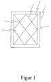
- FIG. 1 schematically shows the representation of a simple mold 1 with a shaping tool surface 2, on which for producing a fiber composite component, a semi-finished fiber product (not shown) can be introduced.
- top view of the mold 1 shows on the tool surface 2 a plurality of injection channels 3, which extend over the entire tool surface 2.
- the injection channels 3 are arranged on the one hand so that they extend from the left lower to the upper right corner and on the other such that they are arranged from the lower right corner to the upper left corner, ie substantially diagonally across the tool surface 2 , Injection channels, which run in the same direction, are substantially parallel.
- crossing points 4 serve the process reliability in the injection of the matrix resin. Because clogged one of the injection channels 3, so a complete impregnation of the semifinished fiber can still be achieved because the matrix resin can take alternative ways due to the plurality of crossing points 4.
- subregions 5 are defined, which subdivide a later-inserted semifinished fiber product (not shown) into just these.
- a linear impregnation of the inserted semi-finished fiber product takes place and impregnation or injection of the fiber material perpendicular to the tool surface 2 in the areas of the injection channels 3 can always be assumed to be safe, forming the sub-areas 5 through the Arrangement of the injection channels 3 arise, the maximum possible unbetränkte volume.
- a larger unconsumed maximum volume than defined by one of the subregions 5 is not possible due to the arrangement of the injection channels 3.
- the required injection pressure can be determined with which the matrix resin in the semifinished fiber must be injected in order to compress the air trapped in the non-saturated subregions 5 to the tolerable, unimpregnated residual volume. If the matrix resin is subjected to this determined injection pressure, then it can be ensured that the entire semifinished fiber product is impregnated with matrix resin, with a maximum of an unimpregnated and dry residual volume of the size of the tolerable unimpregnated fiber residue volume remaining. Thus, a 100% process reliable component impregnation can be ensured.
- FIG. 2 shows a schematic representation of a section through the mold 1, wherein now a semi-finished fiber product 6 has been inserted into the mold. As in FIG. 2 are shown in the tool surface 2 of the mold 1, the injection channels 3, which are formed for the linear injection of the resin along the injection channels 3.
- FIG. 2 in this case shows the impregnation of the semifinished fiber 6 perpendicular to the tool surface 2, starting from the injection channels 3.
- the semifinished fiber evacuated so is alone due to the atmospheric pressure pressed the matrix resin in the direction of the arrows 7 in the fiber fabric 6, which thus at least along the injection channels 3 can achieve a complete impregnation vertically through the semifinished fiber 6. This is always considered safe.
Landscapes
- Chemical & Material Sciences (AREA)
- Engineering & Computer Science (AREA)
- Composite Materials (AREA)
- Mechanical Engineering (AREA)
- Casting Or Compression Moulding Of Plastics Or The Like (AREA)
- Injection Moulding Of Plastics Or The Like (AREA)
- Reinforced Plastic Materials (AREA)
Abstract
Description
- Die Erfindung betrifft ein Verfahren zur Herstellung eines Faserverbundbauteils, wobei ein in ein Formwerkzeug eingebrachtes Faserhalbzeug mit einem Matrixharz injiziert wird.
- Bei der Herstellung von Faserverbundbauteilen, die mittels des Injektionsverfahrens hergestellt werden sollen, wird ein Faserhalbzeug in ein offenes oder geschlossenes Formwerkzeug eingebracht und anschließend mit einem Matrixharz bzw. Injektionsharz infiltriert, bis eine vollständige Tränkung des Faserhalbzeuges erreicht wurde. Nach der vollständigen Tränkung mit dem Matrixharz wird meist unter Zuführung von Wärme das Injektionsharz ausgehärtet, bis sich das fertige Faserverbundbauteil gebildet hat.
- Die Injektion des Matrixharzes in das Faserhalbzeug erfolgt über eine Druckdifferenz zwischen dem Faserhalbzeug und dem Matrixharz. So wird nicht selten vor der Injektion das in ein Vakuum abgedichtete Werkzeugform eingebrachte Faserhalbzeug evakuiert, bis sich ein Feinvakuum im Inneren eingestellt hat. Wird nun die Injektionsleitung des Formwerkzeuges geöffnet, so fließt das Matrixhatz aufgrund der Druckdifferenz in das Innere des Formwerkzeuges und infiltriert dort das Faserhalbzeug. Dabei kann das Matrixharz zusätzlich mit einem Druck beaufschlagt werden, um die Druckdifferenz zwischen Faserhalbzeug und Matrixharz zu erhöhen.
- Ziel dabei ist es, dass das gesamte Faserhalbzeug mit dem Matrixharz vollständig infiltriert wird, um Lufteinschlüsse und trockene Bereiche innerhalb des Faserverbundbauteils zu vermeiden. Derartige Lufteinschlüsse oder trockene Bereiche sind, sofern sie ein bestimmtes Fehlertoleranzvolumen überschreiten, Fehlstellen des Bauteils, welche die Qualität und die Sicherheit des Bauteils beeinträchtigen und bei Bauteilen, die in sicherheitskritischen Bereichen Anwendung finden, als Ausschuss aussortiert werden.
- Die Ursachen für eine unvollständige Tränkung des Faserhalbzeuges resultieren aus dem bevorzugten Strömen des Matrixharzes entlang des niedrigsten Fließwiderstandes. Ein solcher gegenüber dem Rest des Faserhalbzeuges niedrigerer Fließwiderstand kommt beispielsweise an Bauteilkanten, an denen wenige oder gar keine Fasern vorhanden sind, in Bereichen hohen Umformgrade mit abweichenden Faservolumengehalten und entlang von Materialfalten vor. Dabei wird in der Regel versucht, ein Voreilen des Matrixharzes in den Bereichen mit einem niedrigeren Fließwiderstand zu vermeiden, um das Einschließen von Luft und somit das Bilden von trockenen Bereichen zu verhindern.
- Kann das Bilden von trockenen Bereichen nicht vollständig vermieden werden, so wird beispielsweise das Matrixharz nach einer Vortränkung des Fasergeleges mit einem hohen Druck (Nachdruck) beaufschlagt, um sicherzustellen, dass das Faserhalbzeug vollständig mit Matrixharz getränkt und infiltriert wurde. Dies ist jedoch gerade bei größeren Bauteilen problematisch, da mit sehr hohen Drücken (200 bis 500 Bar) gearbeitet werden muss, um gegen den hohen Fließwiderstand innerhalb des Fasergeleges anzukommen und Fehlstellen aufgrund unzureichender Tränkung zu vermeiden. Die verwendeten Formwerkzeuge müssen dabei den hohen Druckbelastungen Stand halten, was sehr zeit- und kostenintensive Arbeiten mit sich bringt. Außerdem muss die Druckbeaufschlagungsanlage zur Erzeugung des hohen Nachdruckes in den Herstellungsprozess integriert werden, was ebenfalls die Herstellungskosten erhöht.
- Aus der
DE 10 2007 013 987 A1 ist ein Werkzeug zur Herstellung eines Faserverbundbauteils bekannt, bei dem mehrere Öffnungen bzw. Nuten in der Werkzeugoberfläche vorgesehen sind, um so ganz oder teilweise auf herkömmliche Fließhilfen verzichten zu können, ohne die Bauteilqualität zu vermindern. - Es ist daher Aufgabe der vorliegenden Erfindung ein Verfahren zur Herstellung eines Faserverbundbauteils anzugeben, dass eine prozesssichere und vollständige Tränkung des Faserverbundbauteils gewährleistet und die aus dem Stand der Technik bekannten Nachteile dabei vermeidet.
- Die Aufgabe wird mit dem eingangs genannten Verfahren zur Herstellung eines Faserverbundbauteils erfindungsgemäß gelöst durch die Schritte:
- a.) Anordnen von Injektionskanälen zur linienförmigen Injektion des Faserhalbzeuges mit dem Matrixharz derart, dass das Faserhalbzeug durch die Anordnung der Injektionskanäle in eine Mehrzahl von Teilbereichen unterteilt wird,
- b.) Ermitteln eines Injektionsdruckes zum Injizieren des Matrixharz in Abhängigkeit von einem Volumen zumindest eines Teilbereiches und von einem vorgegebenen Fehlertoleranzvolumen, das ein tolerierbares ungetränktes Restvolumen des Teilbereiches nach der Injektion des Matrixharzes beschreibt, und
- c.) Injizieren des Matrixharzes mittels der Injektionskanäle in das Faserhalbzeug mit dem ermittelten Injektionsdruck.
- Erfindungsgemäß wird somit vorgeschlagen, das zunächst in einem ersten Schritt a.) Injektionskanäle zur linienförmigen Injektion des Faserhalbzeuges mit dem Matrixharz derart angeordnet werden, dass das Faserhalbzeug durch die Anordnung der Injektionskanäle in eine Mehrzahl von Teilbereichen unterteilt wird. Dies hat zum einen den Vorteil, dass durch die linienförmige Vorverteilung des Matrixharzes über das gesamte Faserhalbzeug der Fließweg des Harzes innerhalb der Fasern bis zur vollständigen Bauteiltränkung reduziert und somit die Injektionszeit verkürzt wird.
- Zum anderen hat die Unterteilung des gesamten Faserhalbzeuges in eine Mehrzahl von Teilbereichen durch die Injektionskanäle den Vorteil, dass für die Frage der vollständigen Tränkung ohne Fehlstellen nunmehr nicht das Bauteil in seiner Gesamtheit betrachtet werden muss, sondern nur ein oder mehrere Teilbereiche entsprechend repräsentativ, wobei eine vollständige Tränkung des Faserhalbzeuges in den Bereichen der Injektionskanäle auch im schlechtesten Fall als gesichert angenommen werden kann. Ausgehend vom schlechtesten Fall kann somit angenommen werden, dass das maximale ungetränkte Volumen des Bauteils dem Volumen der durch die Anordnung der Injektionskanäle entstehenden Teilbereiche entspricht.
- In einem zweiten erfindungsgemäßen Schritt b.) wird dann ein Injektionsdruck zum Injizieren des Matrixharzes in das Faserhalbzeug in Abhängigkeit von dem Volumen zumindest eines Teilbereiches und von einem vorgegebenen Fehlertoleranzvolumen ermittelt. Das vorgegebne Fehlertoleranzvolumen beschreibt dabei ein tolerierbares ungetränktes Restvolumen des jeweiligen Teilbereiches, der nach dem Injizieren des Matrixharzes in das Faserhalbzeug in dem jeweiligen Teilbereich verbleibt. Denn ist das tolerierbare ungetränkte Restvolumen eines Teilbereiches kleiner als eine tolerierbare Fehlergröße, so weißt das Bauteil dementsprechend auch keine Fehlstellen in Bezug auf die Bauteilqualität auf. Der ermittelte Injektionsdruck ist somit dergestalt, dass die Teilbereiche und die damit einhergehenden Bauteilvolumen 100%ig prozesssicher mit dem Matrixharz nach Beendigung des Injektionsvorganges getränkt sind.
- Nach der Ermittlung des Injektionsdruckes wird dann das Matrixharz durch die Injektionskanäle in das Faserhalbzeug mit dem ermittelten Injektionsdruck injiziert, so dass sich nach Abschluss des Verfahrens ein vollständig getränktes Faserhalbzeug ergibt, welches dann zu dem Faserverbundbauteil ausgehärtet werden kann.
- Mit dem erfindungsgemäßen Verfahren kann somit sichergestellt werden, dass sich in den späteren gesamten Faserverbundbauteilen keine ungetränkten Bereiche befinden, die ein größeres als das vorgegebene Fehlertoleranzvolumen aufweisen. Damit kann nicht nur eine schnelle Injektion des Fasergeleges mit dem Matrixharz erreicht werden, sondern auch eine prozesssichere Tränkung derart, dass Fehlstellen von vornherein vermieden werden können. Darüber hinaus muss das Matrixharz nicht mehr pauschal mit einem extrem hohen, prozesssicheren Injektionsdruck beaufschlagt werden, was zu hohen Kosten bezüglich des Formwerkzeuges und der verwendeten Anlagen führt, sondern der verwendete Injektionsdruck kann auf die konkreten Gegebenheiten des entsprechenden Bauteils abgestimmt werden, wobei eine 100%ige Tränkung des Bauteils immer sichergestellt wird.
- Vorteilhafterweise werden die Injektionskanäle derart angeordnet, dass eine erste Anzahl von Injektionskanälen im Wesentlichen parallel zueinander und eine davon verschiedene zweite Anzahl von Injektionskanälen ebenfalls im wesentlichen parallel zueinander ausgerichtet werden, wobei die zweite Anzahl von Injektionskanälen nicht parallel zu der ersten Anzahl von ersten Iniektionskanälen ist. Dadurch ergibt sich, je nach Ausrichtung der ersten Anzahl von Injektionskanälen zu der zweiten Anzahl von Injektionskanälen, ein geometrisches Muster der Injektionskanäle, beispielsweise über die gesamte Bauteiloberfläche, so dass das Faserhalbzeug zum einen in eine Mehrzahl von durch die Injektionskanäle eingeschlossene Teilbereiche unterteilt wird und zum anderen vorteilhafterweise vorgetränkt werden kann. Durch eine geeignete Wahl des Abstandes der Injektionskanäle zueinander kann die Größe der Teilbereiche variiert werden.
- In einer besonderen vorteilhaften Ausführungsform werden die Injektionskanäle derart angeordnet, dass sie sich untereinander zumindest teilweise kreuzen, wobei die Teilbereiche dann durch die von den sich kreuzenden Injektionskanälen eingeschlossenen Bereiche gebildet werden. Neben der Unterteilung des gesamten Faserhalbzeuges in eine Mehrzahl von Teilbereichen hat die Kreuzung der Injektionskanäle den weiteren Vorteil, dass die Prozesssicherheit beim Injizieren des Matrixharz erhöht wird, da bei einem Verstopfen eine der Injektionskanäle das Matrixharz einen alternativen Weg nehmen kann. Somit wird auch letztendlich die Fehlersicherheit hergestellt.
- Des Weiteren ist es besonders vorteilhaft, wenn die Injektionskanäle so angeordnet werden, dass zumindest die Injektionskanäle im Wesentlichen parallel zu der Bauteiloberfläche ausgerichtet sind.
- Vorteilhafterweise werden die Injektionskanäle derart angeordnet, dass im Wesentlichen gleich große Teilbereiche über das gesamte Faserhalbzeug entstehen. Dies vereinfacht die Berechnungsgrundlage. Ist aufgrund der Bauteilgeometrie eine gleich große Verteilung der Teilbereiche nicht möglich, so wird für die Berechnung des Injektionsdruckes derjenige Teilbereich herangezogen, der das größte Volumen aufweist. Somit wird eine vollständige Tränkung immer sichergestellt.
- Darüber hinaus ist es ganz besonders vorteilhaft, wenn die Injektionskanäle derart angeordnet werden, dass voreilgefährdete Bereiche des Faserhalbzeuges als Fließhilfe berücksichtigt werden. Denn mit einer Anordnung der Fließkanäle über das gesamte Faserhalbzeug hinweg können voreilgefährdete Bereiche als Fließhilfe zur Unterstützung mit verwendet werden, da sich ein Voreilen des Matrixharzes in Faserbereichen mit geringem Fließwiderstand nicht mehr negativ auf den Herstellungsprozess auswirken. Durch die Betrachtung des Faserhalbzeuges in einer Mehrzahl von Teilbereichen und ein darauf abgestimmter Injektionsdruck verhindert von vornherein jegliche Bildung von Fehlstellen, die normalerweise durch derartiges Voreilen des Matrixharzes entstehen. Durch die Verwendung derartig voreilgefährdeter Bereiche als Fließhilfe kann das Formwerkzeug einfacher und günstiger hergestellt werden, was letztendlich die Kosten von dem gesamten Herstellungsprozess und somit die Kosten für das fertige Bauteil reduziert.
- In einer weiteren besonderen Ausführungsform wird das geschlossene Formwerkzeug mit dem eingebrachten Faserhalbzeug vor der Injektion des Matrixharzes evakuiert, so dass sich beispielsweise ein Vakuum oder Feinvakuum einstellt. Anschließend wird in einer ersten Druckstufe das Faserhalbzeug mit dem Matrixharz aufgrund der Druckdifferenz zwischen dem evakuierten Bauteil und dem Atmosphärendruck injiziert. Um nun die Volltränkung sicherzustellen, wird in einer zweiten Druckstufe das Matrixharz mit einem Injektionsdruck beaufschlagt der in Schritt b.) berechnet wurde. Vorteilhafterweise wird hierbei der Injektionsdruck weiterhin auch in Abhängigkeit der Druckdifferenz der ersten Druckstufe ermittelt, so dass anschließend ein 100%ig prozesssicheres getränktes Bauteil ergibt. So ist es denkbar, dass der gesamte Differenzdruck zwischen Vorvakuum und Nachdruck zur Fehlerkompression verwendet wird, so dass bspw. bei sehr geringem Vorvakuum der Nachdruck niedriger gewählt werden kann.
- Die Ermittlung des Injektionsdruckes kann dabei beispielsweise mit Hilfe des idealen Gasgesetzes (bspw. überschlagsweise) zur Komprimierung von Gasen ermittelt werden, dass hierfür notwendige Berechnungsgrundlage liefert, da letztendlich bei der Injektion des Matrixharzes die in den Teilbereichen vorhandene Luft auf das tolerierbare Fehlerrestvolumen komprimiert werden muss. Die Erfindung wird anhand der beigefügten Zeichnungen näher erläutert. Es zeigen:
- Figur 1
- - Schematisch Darstellung eines einfachen Formwerkzeuges zur Durchführung des erfindungsgemäßen Verfahrens;
- Figur 2
- - schematisch Darstellung eines Schnittes durch ein derartiges Formwerkzeug mit eingebrachtem Faserhalbzeug.
-
Figur 1 zeigt schematisch die Darstellung eines einfachen Formwerkzeuges 1 mit einer formgebenden Werkzeugoberfläche 2, auf die zur Herstellung eines Faserverbundbauteils ein Faserhalbzeug (nicht dargestellt) einbringbar ist. Die inFigur 1 dargestellte Draufsicht auf das Formwerkzeug 1 zeigt auf der Werkzeugoberfläche 2 eine Mehrzahl von Injektionskanälen 3, die über die gesamte Werkzeugoberfläche 2 verlaufen. Die Injektionskanäle 3 sind dabei zum einen so angeordnet, dass sie von der linken unteren in die obere rechte Ecke verlaufen und zum anderen derart, dass sie von der rechten unteren in die linke obere Ecke, also im Wesentlichen diagonal, über die Werkzeugoberfläche 2 angeordnet sind. Injektionskanäle, die in dieselbe Richtung verlaufen, sind dabei im Wesentlichen parallel. - Durch die Anordnung der Injektionskanäle 3 in jeweils unterschiedlichen diagonalen Verlaufsrichtungen ergeben sich Kreuzungspunkte 4, die der Prozesssicherheit bei der Injektion des Matrixharzes dienen. Denn verstopft einer der Injektionskanäle 3, so kann eine vollständige Tränkung des Faserhalbzeuges dennoch erreicht werden, da das Matrixharz alternative Wege aufgrund der Vielzahl der Kreuzungspunkte 4 nehmen kann.
- Darüber hinaus werden durch die unterschiedliche Ausrichtung der Injektionskanäle und die Bildung der Kreuzungspunkte Teilbereiche 5 definiert die ein später eingelegtes Faserhalbzeug (nicht gezeigt) in eben diese unterteilt. Da bei einer Injektion des Matrixharzes in die Injektionskanäle 3 zunächst eine linienförmige Tränkung des eingelegten Faserhalbzeuges erfolgt und eine Tränkung bzw. Injektion des Fasermaterials senkrecht zur Werkzeugoberfläche 2 in den Bereichen der Injektionskanäle 3 immer als sicher angenommen werden kann, bilden die Teilbereiche 5, die durch die Anordnung der Injektionskanäle 3 entstehen, das maximal mögliche ungetränkte Volumen. Ein größeres ungetränktes maximales Volumens als durch einen der Teilbereiche 5 definiert wird, ist aufgrund der Anordnung der Injektionskanäle 3 nicht möglich.
- Durch die Annahme, dass die durch die Teilbereiche 5 gebildeten Volumen des Faserhalbzeuges den maximal größten ungetränkten Bereich darstellen und bei einem vorgegebenen Fehlertoleranzvolumen, das als ein tolerierbarer ungetränkter Restbereich (Restvolumen) akzeptabel ist, kann der benötigte Injektionsdruck ermittelt werden, mit dem das Matrixharz in das Faserhalbzeug injiziert werden muss, um die in den ungetränkten Teilbereichen 5 eingeschlossene Luft auf das tolerierbare ungetränkte Restvolumen zu komprimieren. Wird das Matrixharz mit diesen ermittelten Injektionsdruck beaufschlagt, so kann sichergestellt werden, dass das gesamte Faserhalbzeug mit Matrixharz getränkt ist, wobei maximal ein ungetränktes und trockenes Restvolumen der Größe des tolerierbaren ungetränkten Faserrestvolumens verbleiben würden. Somit kann eine 100%ig prozesssichere Bauteiltränkung sichergestellt werden.
-
Figur 2 zeigt eine schematische Darstellung eines Schnittes durch das Formwerkzeug 1, wobei nunmehr ein Faserhalbzeug 6 in das Formwerkzeug eingelegt wurde. Wie inFigur 2 dargestellt befinden sich in der Werkzeugoberfläche 2 des Formwerkzeuges 1 die Injektionskanäle 3, die zur linienförmigen Injektion des Harzes entlang der Injektionskanäle 3 ausgebildet sind. -
Figur 2 zeigt hierbei die Tränkung des Faserhalbzeuges 6 senkrecht zu der Werkzeugoberfläche 2, ausgehend von den Injektionskanälen 3. Wurde das Faserhalbzeug evakuiert, so wird alleine aufgrund des Atmosphärendruckes das Matrixharz in Richtung der Pfeile 7 in das Fasergelege 6 gedrückt, wobei sich somit zumindest entlang der Injektionskanäle 3 eine vollständige Tränkung senkrecht durch das Faserhalbzeug 6 erreichen lässt. Dies wird immer als sicher angenommen. - Werden darüber hinaus auch noch voreilgefährdete Bereiche als Fließhilfe berücksichtigt, so können durch Einsparung von Injektionskanälen die Kosten für das Formwerkzeug reduziert und somit der gesamte Herstellungsprozess kostengünstiger durchgeführt werden.
Claims (8)
- Verfahren zur Herstellung eines Faserverbundbauteils, wobei ein in einem Formwerkzeug (1) eingebrachtes Faserhalbzeug (6) mit einem Matrixharz injiziert wird, gekennzeichnet durch die Schritte:a.) Anordnen von Injektionskanälen (3) zur linienförmigen Injektion des Faserhalbzeuges entlang der Injektionskanäle (3) mit dem Matrixharz derart, dass das Faserhalbzeug (6) durch die Anordnung der Injektionskanäle (3) in eine Mehrzahl von Teilbereichen (5) unterteilt wird,b.) Ermitteln eines Injektionsdruckes zum Injizieren des Matrixharzes in Abhängigkeit von einem Volumen zumindest eines Teilbereiches (5) und von einem vorgegebenen Fehlertoleranzvolumen, das ein tolerierbares ungetränktes Restvolumen des Teilbereichs (5) nach der Injektion des Matrixharz beschreibt, undc.) Injizieren des Matrixharz mittels der Injektionskanäle (3) in das Faserhalbzeug (6) mit dem ermittelten Injektionsdruck.
- Verfahren nach Anspruch 1, gekennzeichnet durch Anordnen der Injektionskanäle (3) in einer Werkzeugoberfläche (2) des Formwerkzeuges (1).
- Verfahren nach Anspruch 1 oder 2, gekennzeichnet durch Anordnen der Injektionskanäle (3) derart, dass eine erste Anzahl von Injektionskanälen (3) im Wesentlichen parallel zueinander und eine zweite Anzahl von Injektionskanälen (3) im Wesentlichen parallel zueinander ausgerichtet werden, wobei die zweite Anzahl von Injektionskanälen (3) nicht parallel zu der ersten Anzahl von Injektionskanälen (3) ist.
- Verfahren nach einem der vorhergehenden Ansprüche, gekennzeichnet durch Anordnen der Injektionskanäle (3) derart, dass die Injektionskanäle (3) sich zumindest teilweise untereinander kreuzen, wobei die Teilbereiche (5) durch die von sich kreuzenden Injektionskanälen (3) eingeschlossenen Bereichen gebildet werden.
- Verfahren nach einem der vorhergehenden Ansprüche, gekennzeichnet durch Anordnen der Injektionskanäle (3) derart, dass zumindest ein Teil der Injektionskanäle (3) im Wesentlichen parallel zu einer Bauteiloberfläche des Faserhalbzeuges (6) ausgerichtet sind.
- Verfahren nach einem der vorhergehenden Ansprüche, gekennzeichnet durch Anordnen der Injektionskanäle (3) derart, dass im Wesentlichen gleichgroße Teilbereiche (5) entstehen.
- Verfahren nach einem der vorhergehenden Ansprüche, gekennzeichnet durch Anordnen der Injektionskanäle (3) derart, dass voreilgefährdete Bereiche des Faserhalbzeuges (6) als Fließhilfen berücksichtigt werden.
- Verfahren nach einem der vorhergehenden Ansprüche, gekennzeichnet durch Evakuieren des Formwerkzeuges (1) vor dem Injizieren des Matrixharzes, wobei in Schritt b) der Injektionsdruck weiterhin in Abhängigkeit von einer Druckdifferenz zwischen dem Innendruck des evakuierten Formwerkzeuges und dem äußeren Atmosphärendruck ermittelt wird.
Applications Claiming Priority (1)
| Application Number | Priority Date | Filing Date | Title |
|---|---|---|---|
| DE102011111452A DE102011111452A1 (de) | 2011-08-30 | 2011-08-30 | Herstellung eines Faserverbundbauteils |
Publications (3)
| Publication Number | Publication Date |
|---|---|
| EP2565020A2 true EP2565020A2 (de) | 2013-03-06 |
| EP2565020A3 EP2565020A3 (de) | 2014-01-15 |
| EP2565020B1 EP2565020B1 (de) | 2017-04-19 |
Family
ID=46796396
Family Applications (1)
| Application Number | Title | Priority Date | Filing Date |
|---|---|---|---|
| EP12182355.3A Not-in-force EP2565020B1 (de) | 2011-08-30 | 2012-08-30 | Herstellung eines Faserverbundbauteils |
Country Status (2)
| Country | Link |
|---|---|
| EP (1) | EP2565020B1 (de) |
| DE (1) | DE102011111452A1 (de) |
Cited By (2)
| Publication number | Priority date | Publication date | Assignee | Title |
|---|---|---|---|---|
| EP3124220A1 (de) * | 2015-07-20 | 2017-02-01 | Blade Dynamics Limited | Verfahren zum formen eines verbundwerkstoffes sowie form |
| US11738524B2 (en) | 2017-05-24 | 2023-08-29 | Bayerische Motoren Werke Aktiengesellschaft | Method for identifying a fiber-reinforced plastic component, and a resin transfer molding (RTM) mold |
Families Citing this family (2)
| Publication number | Priority date | Publication date | Assignee | Title |
|---|---|---|---|---|
| DE102013226827A1 (de) | 2013-12-20 | 2015-06-25 | Bayerische Motoren Werke Aktiengesellschaft | Werkzeug zur Herstellung von Faserverbundbauteilen |
| DE102015005492B4 (de) | 2015-04-30 | 2023-05-04 | Airbus Defence and Space GmbH | Fließhilfe für einen Infusionsaufbau sowie Infusionsaufbau und Verfahren zum Infiltrieren eines Fasermaterials |
Citations (1)
| Publication number | Priority date | Publication date | Assignee | Title |
|---|---|---|---|---|
| DE102007013987A1 (de) | 2006-08-17 | 2008-02-21 | Airbus Deutschland Gmbh | Werkzeug zur Herstellung von Faserverbundbauteilen |
Family Cites Families (3)
| Publication number | Priority date | Publication date | Assignee | Title |
|---|---|---|---|---|
| US5958325A (en) * | 1995-06-07 | 1999-09-28 | Tpi Technology, Inc. | Large composite structures and a method for production of large composite structures incorporating a resin distribution network |
| DE19912723C1 (de) * | 1999-03-20 | 2000-11-09 | Dlr Ev | Verfahren und Vorrichtung zur Bestimmung der Durchtränkung von Faserhalbzeugen |
| WO2009003476A1 (en) * | 2007-06-29 | 2009-01-08 | Lm Glasfiber A/S | Method of using a formable core block for a resin impregnation process |
-
2011
- 2011-08-30 DE DE102011111452A patent/DE102011111452A1/de not_active Withdrawn
-
2012
- 2012-08-30 EP EP12182355.3A patent/EP2565020B1/de not_active Not-in-force
Patent Citations (1)
| Publication number | Priority date | Publication date | Assignee | Title |
|---|---|---|---|---|
| DE102007013987A1 (de) | 2006-08-17 | 2008-02-21 | Airbus Deutschland Gmbh | Werkzeug zur Herstellung von Faserverbundbauteilen |
Cited By (3)
| Publication number | Priority date | Publication date | Assignee | Title |
|---|---|---|---|---|
| EP3124220A1 (de) * | 2015-07-20 | 2017-02-01 | Blade Dynamics Limited | Verfahren zum formen eines verbundwerkstoffes sowie form |
| US10486377B2 (en) | 2015-07-20 | 2019-11-26 | Blade Dynamics Limited | Method of moulding a composite article and mould |
| US11738524B2 (en) | 2017-05-24 | 2023-08-29 | Bayerische Motoren Werke Aktiengesellschaft | Method for identifying a fiber-reinforced plastic component, and a resin transfer molding (RTM) mold |
Also Published As
| Publication number | Publication date |
|---|---|
| EP2565020A3 (de) | 2014-01-15 |
| EP2565020B1 (de) | 2017-04-19 |
| DE102011111452A1 (de) | 2013-02-28 |
Similar Documents
| Publication | Publication Date | Title |
|---|---|---|
| EP2709810B1 (de) | Verfahren und vorrichtung zum transportieren einer aus einem flächigen fasergewebe ausgeschnittenen faserkontur im zuge der herstellung von faserverstärkten kunststoff-formteilen | |
| DE102012110354B4 (de) | Formwerkzeug, Steuermittel, Verfahren und Anlage zum Herstellen eines, vorzugsweise faserverstärkten, Kunststoffbauteils | |
| EP1916091B1 (de) | Verfahren zur Herstellung von Faserverbundbauteilen | |
| DE102007013987A1 (de) | Werkzeug zur Herstellung von Faserverbundbauteilen | |
| EP2911852A1 (de) | Verfahren und anlage zum herstellen eines faserverstärkten kunststoffbauteils | |
| DE102007046734A1 (de) | Verfahren und Formwerkzeug zur Herstellung eines faserverstärkten Kunststoffbauteils | |
| DE4040746A1 (de) | Querformwerkzeug zum verdichten von verbundmaterialien | |
| DE102011083688A1 (de) | Formwerkzeug zum Herstellen von faserverstärkten Kunststoffbauteilen | |
| EP2565020B1 (de) | Herstellung eines Faserverbundbauteils | |
| EP2769832B1 (de) | Verfahren zur Herstellung eines flächigen Leichtbaumaterials bestehend aus Verstärkungsfasern und thermoplastischem Kunststoff | |
| DE102013107991A1 (de) | Verfahren zur endkonturgetreuen Herstellung mechanisch hoch belastbarer Kunststoff-Bauteile | |
| EP3778163B1 (de) | Verfahren zur herstellung eines holz-formteils | |
| EP1469986A1 (de) | Verfahren und vorrichtungen zur herstellung von faserverst r kten bauteilen | |
| DE102011110206B4 (de) | Formwerkzeug | |
| EP2324995B1 (de) | Verfahren zur Herstellung eines Faserverbundbauteils | |
| EP2842729B1 (de) | Verfahren zur Herstellung von Faserverbundbauteilen mit integrierter Isolation | |
| DE102014224720A1 (de) | Verfahren zur Herstellung eines schnittbearbeiteten Formteils mit einer Kunststoffmatrix und Verstärkungsfasern | |
| EP3611012A1 (de) | Vorrichtung und verfahren zum herstellen eines bauteils | |
| DE102013222358B4 (de) | Werkzeug sowie Verfahren zur Herstellung eines faserverstärkten Kunststoffteils | |
| DE102021124906A1 (de) | Herstellungsverfahren für Faserverbundelemente, Faserverbundelement und Faserverbundwerkzeuganordnung | |
| DE102017215693A1 (de) | Pultrusionswerkzeug und Verfahren zur Herstellung eines faserverstärkten Profilbauteils | |
| DE102008057782B4 (de) | Vorrichtung und Verfahren zum Umfalten eines zur Herstellung eines Faserverbundbauteils vorgesehenen textilen Halbzeugprofils, sowie Verfahren zur Herstellung eines mehrlagigen textilen Halbzeugprofils | |
| DE102015221261A1 (de) | Verfahren zur Herstellung eines Fasermatrixhalbzeugs | |
| EP2769833A1 (de) | Flächiges Leichtbaumaterial aus Verstärkungsfasern und thermoplastischem Kunststoff | |
| DE102014224741A1 (de) | Verfahren zur Herstellung von Vorformlingen sowie eines Faserverbundbauteils und Faserverbundbauteil |
Legal Events
| Date | Code | Title | Description |
|---|---|---|---|
| PUAI | Public reference made under article 153(3) epc to a published international application that has entered the european phase |
Free format text: ORIGINAL CODE: 0009012 |
|
| AK | Designated contracting states |
Kind code of ref document: A2 Designated state(s): AL AT BE BG CH CY CZ DE DK EE ES FI FR GB GR HR HU IE IS IT LI LT LU LV MC MK MT NL NO PL PT RO RS SE SI SK SM TR |
|
| AX | Request for extension of the european patent |
Extension state: BA ME |
|
| RIN1 | Information on inventor provided before grant (corrected) |
Inventor name: FRIEDRICH, MARTIN Inventor name: KOENNICKE, DANIELA Inventor name: WOLFF, JOHANNES Inventor name: HINDERSMANN, ARNE |
|
| RIN1 | Information on inventor provided before grant (corrected) |
Inventor name: HINDERSMANN, ARNE Inventor name: FRIEDRICH, MARTIN Inventor name: WOLFF, JOHANNES Inventor name: KOENNICKE, DANIELA |
|
| PUAL | Search report despatched |
Free format text: ORIGINAL CODE: 0009013 |
|
| AK | Designated contracting states |
Kind code of ref document: A3 Designated state(s): AL AT BE BG CH CY CZ DE DK EE ES FI FR GB GR HR HU IE IS IT LI LT LU LV MC MK MT NL NO PL PT RO RS SE SI SK SM TR |
|
| AX | Request for extension of the european patent |
Extension state: BA ME |
|
| RIC1 | Information provided on ipc code assigned before grant |
Ipc: B29C 70/44 20060101ALI20131206BHEP Ipc: B29C 70/54 20060101AFI20131206BHEP |
|
| 17P | Request for examination filed |
Effective date: 20140715 |
|
| RBV | Designated contracting states (corrected) |
Designated state(s): AL AT BE BG CH CY CZ DE DK EE ES FI FR GB GR HR HU IE IS IT LI LT LU LV MC MK MT NL NO PL PT RO RS SE SI SK SM TR |
|
| 17Q | First examination report despatched |
Effective date: 20150604 |
|
| GRAP | Despatch of communication of intention to grant a patent |
Free format text: ORIGINAL CODE: EPIDOSNIGR1 |
|
| STAA | Information on the status of an ep patent application or granted ep patent |
Free format text: STATUS: GRANT OF PATENT IS INTENDED |
|
| INTG | Intention to grant announced |
Effective date: 20161123 |
|
| GRAS | Grant fee paid |
Free format text: ORIGINAL CODE: EPIDOSNIGR3 |
|
| GRAA | (expected) grant |
Free format text: ORIGINAL CODE: 0009210 |
|
| STAA | Information on the status of an ep patent application or granted ep patent |
Free format text: STATUS: THE PATENT HAS BEEN GRANTED |
|
| AK | Designated contracting states |
Kind code of ref document: B1 Designated state(s): AL AT BE BG CH CY CZ DE DK EE ES FI FR GB GR HR HU IE IS IT LI LT LU LV MC MK MT NL NO PL PT RO RS SE SI SK SM TR |
|
| REG | Reference to a national code |
Ref country code: GB Ref legal event code: FG4D Free format text: NOT ENGLISH |
|
| REG | Reference to a national code |
Ref country code: CH Ref legal event code: EP |
|
| REG | Reference to a national code |
Ref country code: AT Ref legal event code: REF Ref document number: 885530 Country of ref document: AT Kind code of ref document: T Effective date: 20170515 |
|
| REG | Reference to a national code |
Ref country code: IE Ref legal event code: FG4D Free format text: LANGUAGE OF EP DOCUMENT: GERMAN |
|
| REG | Reference to a national code |
Ref country code: DE Ref legal event code: R096 Ref document number: 502012010098 Country of ref document: DE |
|
| REG | Reference to a national code |
Ref country code: FR Ref legal event code: PLFP Year of fee payment: 6 |
|
| REG | Reference to a national code |
Ref country code: NL Ref legal event code: MP Effective date: 20170419 |
|
| REG | Reference to a national code |
Ref country code: LT Ref legal event code: MG4D |
|
| PG25 | Lapsed in a contracting state [announced via postgrant information from national office to epo] |
Ref country code: NL Free format text: LAPSE BECAUSE OF FAILURE TO SUBMIT A TRANSLATION OF THE DESCRIPTION OR TO PAY THE FEE WITHIN THE PRESCRIBED TIME-LIMIT Effective date: 20170419 |
|
| PG25 | Lapsed in a contracting state [announced via postgrant information from national office to epo] |
Ref country code: GR Free format text: LAPSE BECAUSE OF FAILURE TO SUBMIT A TRANSLATION OF THE DESCRIPTION OR TO PAY THE FEE WITHIN THE PRESCRIBED TIME-LIMIT Effective date: 20170720 Ref country code: LT Free format text: LAPSE BECAUSE OF FAILURE TO SUBMIT A TRANSLATION OF THE DESCRIPTION OR TO PAY THE FEE WITHIN THE PRESCRIBED TIME-LIMIT Effective date: 20170419 Ref country code: HR Free format text: LAPSE BECAUSE OF FAILURE TO SUBMIT A TRANSLATION OF THE DESCRIPTION OR TO PAY THE FEE WITHIN THE PRESCRIBED TIME-LIMIT Effective date: 20170419 Ref country code: ES Free format text: LAPSE BECAUSE OF FAILURE TO SUBMIT A TRANSLATION OF THE DESCRIPTION OR TO PAY THE FEE WITHIN THE PRESCRIBED TIME-LIMIT Effective date: 20170419 Ref country code: NO Free format text: LAPSE BECAUSE OF FAILURE TO SUBMIT A TRANSLATION OF THE DESCRIPTION OR TO PAY THE FEE WITHIN THE PRESCRIBED TIME-LIMIT Effective date: 20170719 Ref country code: FI Free format text: LAPSE BECAUSE OF FAILURE TO SUBMIT A TRANSLATION OF THE DESCRIPTION OR TO PAY THE FEE WITHIN THE PRESCRIBED TIME-LIMIT Effective date: 20170419 |
|
| PG25 | Lapsed in a contracting state [announced via postgrant information from national office to epo] |
Ref country code: SE Free format text: LAPSE BECAUSE OF FAILURE TO SUBMIT A TRANSLATION OF THE DESCRIPTION OR TO PAY THE FEE WITHIN THE PRESCRIBED TIME-LIMIT Effective date: 20170419 Ref country code: BG Free format text: LAPSE BECAUSE OF FAILURE TO SUBMIT A TRANSLATION OF THE DESCRIPTION OR TO PAY THE FEE WITHIN THE PRESCRIBED TIME-LIMIT Effective date: 20170719 Ref country code: IS Free format text: LAPSE BECAUSE OF FAILURE TO SUBMIT A TRANSLATION OF THE DESCRIPTION OR TO PAY THE FEE WITHIN THE PRESCRIBED TIME-LIMIT Effective date: 20170819 Ref country code: RS Free format text: LAPSE BECAUSE OF FAILURE TO SUBMIT A TRANSLATION OF THE DESCRIPTION OR TO PAY THE FEE WITHIN THE PRESCRIBED TIME-LIMIT Effective date: 20170419 Ref country code: LV Free format text: LAPSE BECAUSE OF FAILURE TO SUBMIT A TRANSLATION OF THE DESCRIPTION OR TO PAY THE FEE WITHIN THE PRESCRIBED TIME-LIMIT Effective date: 20170419 Ref country code: PL Free format text: LAPSE BECAUSE OF FAILURE TO SUBMIT A TRANSLATION OF THE DESCRIPTION OR TO PAY THE FEE WITHIN THE PRESCRIBED TIME-LIMIT Effective date: 20170419 |
|
| REG | Reference to a national code |
Ref country code: DE Ref legal event code: R097 Ref document number: 502012010098 Country of ref document: DE |
|
| PG25 | Lapsed in a contracting state [announced via postgrant information from national office to epo] |
Ref country code: DK Free format text: LAPSE BECAUSE OF FAILURE TO SUBMIT A TRANSLATION OF THE DESCRIPTION OR TO PAY THE FEE WITHIN THE PRESCRIBED TIME-LIMIT Effective date: 20170419 Ref country code: SK Free format text: LAPSE BECAUSE OF FAILURE TO SUBMIT A TRANSLATION OF THE DESCRIPTION OR TO PAY THE FEE WITHIN THE PRESCRIBED TIME-LIMIT Effective date: 20170419 Ref country code: EE Free format text: LAPSE BECAUSE OF FAILURE TO SUBMIT A TRANSLATION OF THE DESCRIPTION OR TO PAY THE FEE WITHIN THE PRESCRIBED TIME-LIMIT Effective date: 20170419 Ref country code: RO Free format text: LAPSE BECAUSE OF FAILURE TO SUBMIT A TRANSLATION OF THE DESCRIPTION OR TO PAY THE FEE WITHIN THE PRESCRIBED TIME-LIMIT Effective date: 20170419 Ref country code: CZ Free format text: LAPSE BECAUSE OF FAILURE TO SUBMIT A TRANSLATION OF THE DESCRIPTION OR TO PAY THE FEE WITHIN THE PRESCRIBED TIME-LIMIT Effective date: 20170419 |
|
| PLBE | No opposition filed within time limit |
Free format text: ORIGINAL CODE: 0009261 |
|
| STAA | Information on the status of an ep patent application or granted ep patent |
Free format text: STATUS: NO OPPOSITION FILED WITHIN TIME LIMIT |
|
| PG25 | Lapsed in a contracting state [announced via postgrant information from national office to epo] |
Ref country code: SM Free format text: LAPSE BECAUSE OF FAILURE TO SUBMIT A TRANSLATION OF THE DESCRIPTION OR TO PAY THE FEE WITHIN THE PRESCRIBED TIME-LIMIT Effective date: 20170419 Ref country code: IT Free format text: LAPSE BECAUSE OF FAILURE TO SUBMIT A TRANSLATION OF THE DESCRIPTION OR TO PAY THE FEE WITHIN THE PRESCRIBED TIME-LIMIT Effective date: 20170419 |
|
| 26N | No opposition filed |
Effective date: 20180122 |
|
| REG | Reference to a national code |
Ref country code: CH Ref legal event code: PL |
|
| PG25 | Lapsed in a contracting state [announced via postgrant information from national office to epo] |
Ref country code: MC Free format text: LAPSE BECAUSE OF FAILURE TO SUBMIT A TRANSLATION OF THE DESCRIPTION OR TO PAY THE FEE WITHIN THE PRESCRIBED TIME-LIMIT Effective date: 20170419 |
|
| GBPC | Gb: european patent ceased through non-payment of renewal fee |
Effective date: 20170830 |
|
| PG25 | Lapsed in a contracting state [announced via postgrant information from national office to epo] |
Ref country code: CH Free format text: LAPSE BECAUSE OF NON-PAYMENT OF DUE FEES Effective date: 20170831 Ref country code: LI Free format text: LAPSE BECAUSE OF NON-PAYMENT OF DUE FEES Effective date: 20170831 |
|
| REG | Reference to a national code |
Ref country code: IE Ref legal event code: MM4A |
|
| PG25 | Lapsed in a contracting state [announced via postgrant information from national office to epo] |
Ref country code: SI Free format text: LAPSE BECAUSE OF FAILURE TO SUBMIT A TRANSLATION OF THE DESCRIPTION OR TO PAY THE FEE WITHIN THE PRESCRIBED TIME-LIMIT Effective date: 20170419 |
|
| REG | Reference to a national code |
Ref country code: BE Ref legal event code: MM Effective date: 20170831 |
|
| PG25 | Lapsed in a contracting state [announced via postgrant information from national office to epo] |
Ref country code: LU Free format text: LAPSE BECAUSE OF NON-PAYMENT OF DUE FEES Effective date: 20170830 |
|
| REG | Reference to a national code |
Ref country code: FR Ref legal event code: PLFP Year of fee payment: 7 |
|
| PG25 | Lapsed in a contracting state [announced via postgrant information from national office to epo] |
Ref country code: GB Free format text: LAPSE BECAUSE OF NON-PAYMENT OF DUE FEES Effective date: 20170830 Ref country code: IE Free format text: LAPSE BECAUSE OF NON-PAYMENT OF DUE FEES Effective date: 20170830 |
|
| PG25 | Lapsed in a contracting state [announced via postgrant information from national office to epo] |
Ref country code: BE Free format text: LAPSE BECAUSE OF NON-PAYMENT OF DUE FEES Effective date: 20170831 |
|
| PG25 | Lapsed in a contracting state [announced via postgrant information from national office to epo] |
Ref country code: MT Free format text: LAPSE BECAUSE OF FAILURE TO SUBMIT A TRANSLATION OF THE DESCRIPTION OR TO PAY THE FEE WITHIN THE PRESCRIBED TIME-LIMIT Effective date: 20170419 |
|
| REG | Reference to a national code |
Ref country code: AT Ref legal event code: MM01 Ref document number: 885530 Country of ref document: AT Kind code of ref document: T Effective date: 20170830 |
|
| PGFP | Annual fee paid to national office [announced via postgrant information from national office to epo] |
Ref country code: FR Payment date: 20180718 Year of fee payment: 7 |
|
| PG25 | Lapsed in a contracting state [announced via postgrant information from national office to epo] |
Ref country code: AT Free format text: LAPSE BECAUSE OF NON-PAYMENT OF DUE FEES Effective date: 20170830 |
|
| PG25 | Lapsed in a contracting state [announced via postgrant information from national office to epo] |
Ref country code: HU Free format text: LAPSE BECAUSE OF FAILURE TO SUBMIT A TRANSLATION OF THE DESCRIPTION OR TO PAY THE FEE WITHIN THE PRESCRIBED TIME-LIMIT; INVALID AB INITIO Effective date: 20120830 |
|
| PG25 | Lapsed in a contracting state [announced via postgrant information from national office to epo] |
Ref country code: CY Free format text: LAPSE BECAUSE OF NON-PAYMENT OF DUE FEES Effective date: 20170419 |
|
| PG25 | Lapsed in a contracting state [announced via postgrant information from national office to epo] |
Ref country code: MK Free format text: LAPSE BECAUSE OF FAILURE TO SUBMIT A TRANSLATION OF THE DESCRIPTION OR TO PAY THE FEE WITHIN THE PRESCRIBED TIME-LIMIT Effective date: 20170419 |
|
| PG25 | Lapsed in a contracting state [announced via postgrant information from national office to epo] |
Ref country code: TR Free format text: LAPSE BECAUSE OF FAILURE TO SUBMIT A TRANSLATION OF THE DESCRIPTION OR TO PAY THE FEE WITHIN THE PRESCRIBED TIME-LIMIT Effective date: 20170419 |
|
| PG25 | Lapsed in a contracting state [announced via postgrant information from national office to epo] |
Ref country code: PT Free format text: LAPSE BECAUSE OF FAILURE TO SUBMIT A TRANSLATION OF THE DESCRIPTION OR TO PAY THE FEE WITHIN THE PRESCRIBED TIME-LIMIT Effective date: 20170419 |
|
| PG25 | Lapsed in a contracting state [announced via postgrant information from national office to epo] |
Ref country code: FR Free format text: LAPSE BECAUSE OF NON-PAYMENT OF DUE FEES Effective date: 20190831 Ref country code: AL Free format text: LAPSE BECAUSE OF FAILURE TO SUBMIT A TRANSLATION OF THE DESCRIPTION OR TO PAY THE FEE WITHIN THE PRESCRIBED TIME-LIMIT Effective date: 20170419 |
|
| PGFP | Annual fee paid to national office [announced via postgrant information from national office to epo] |
Ref country code: DE Payment date: 20220630 Year of fee payment: 11 |
|
| REG | Reference to a national code |
Ref country code: DE Ref legal event code: R119 Ref document number: 502012010098 Country of ref document: DE |
|
| PG25 | Lapsed in a contracting state [announced via postgrant information from national office to epo] |
Ref country code: DE Free format text: LAPSE BECAUSE OF NON-PAYMENT OF DUE FEES Effective date: 20240301 |