EP2564111B1 - Ring light illuminator and beam shaper for ring light illuminator - Google Patents
Ring light illuminator and beam shaper for ring light illuminator Download PDFInfo
- Publication number
- EP2564111B1 EP2564111B1 EP11774522.4A EP11774522A EP2564111B1 EP 2564111 B1 EP2564111 B1 EP 2564111B1 EP 11774522 A EP11774522 A EP 11774522A EP 2564111 B1 EP2564111 B1 EP 2564111B1
- Authority
- EP
- European Patent Office
- Prior art keywords
- light
- beam shaper
- lens
- homogenizing rod
- ring
- Prior art date
- Legal status (The legal status is an assumption and is not a legal conclusion. Google has not performed a legal analysis and makes no representation as to the accuracy of the status listed.)
- Active
Links
- 230000003287 optical effect Effects 0.000 claims description 28
- 238000005286 illumination Methods 0.000 claims description 20
- 238000003384 imaging method Methods 0.000 claims description 5
- 239000000463 material Substances 0.000 claims description 4
- 239000011521 glass Substances 0.000 claims description 2
- 239000007787 solid Substances 0.000 claims description 2
- 239000011248 coating agent Substances 0.000 claims 1
- 238000000576 coating method Methods 0.000 claims 1
- 238000001816 cooling Methods 0.000 claims 1
- 238000007493 shaping process Methods 0.000 description 9
- 238000007689 inspection Methods 0.000 description 5
- 150000001875 compounds Chemical class 0.000 description 4
- 230000000873 masking effect Effects 0.000 description 3
- 239000013307 optical fiber Substances 0.000 description 3
- 230000000694 effects Effects 0.000 description 2
- 230000010354 integration Effects 0.000 description 2
- 230000004075 alteration Effects 0.000 description 1
- 239000012141 concentrate Substances 0.000 description 1
- 230000007423 decrease Effects 0.000 description 1
- 230000001747 exhibiting effect Effects 0.000 description 1
- 229910052736 halogen Inorganic materials 0.000 description 1
- 150000002367 halogens Chemical class 0.000 description 1
- 230000001678 irradiating effect Effects 0.000 description 1
- 230000001788 irregular Effects 0.000 description 1
- 238000000386 microscopy Methods 0.000 description 1
- 238000012986 modification Methods 0.000 description 1
- 230000004048 modification Effects 0.000 description 1
- 239000012780 transparent material Substances 0.000 description 1
Images


Classifications
-
- G—PHYSICS
- G02—OPTICS
- G02B—OPTICAL ELEMENTS, SYSTEMS OR APPARATUS
- G02B21/00—Microscopes
- G02B21/06—Means for illuminating specimens
- G02B21/08—Condensers
- G02B21/082—Condensers for incident illumination only
- G02B21/084—Condensers for incident illumination only having annular illumination around the objective
-
- F—MECHANICAL ENGINEERING; LIGHTING; HEATING; WEAPONS; BLASTING
- F21—LIGHTING
- F21V—FUNCTIONAL FEATURES OR DETAILS OF LIGHTING DEVICES OR SYSTEMS THEREOF; STRUCTURAL COMBINATIONS OF LIGHTING DEVICES WITH OTHER ARTICLES, NOT OTHERWISE PROVIDED FOR
- F21V5/00—Refractors for light sources
- F21V5/04—Refractors for light sources of lens shape
- F21V5/045—Refractors for light sources of lens shape the lens having discontinuous faces, e.g. Fresnel lenses
-
- G—PHYSICS
- G01—MEASURING; TESTING
- G01N—INVESTIGATING OR ANALYSING MATERIALS BY DETERMINING THEIR CHEMICAL OR PHYSICAL PROPERTIES
- G01N21/00—Investigating or analysing materials by the use of optical means, i.e. using sub-millimetre waves, infrared, visible or ultraviolet light
- G01N21/84—Systems specially adapted for particular applications
- G01N21/88—Investigating the presence of flaws or contamination
- G01N21/8806—Specially adapted optical and illumination features
-
- G—PHYSICS
- G02—OPTICS
- G02B—OPTICAL ELEMENTS, SYSTEMS OR APPARATUS
- G02B19/00—Condensers, e.g. light collectors or similar non-imaging optics
-
- G—PHYSICS
- G02—OPTICS
- G02B—OPTICAL ELEMENTS, SYSTEMS OR APPARATUS
- G02B21/00—Microscopes
- G02B21/06—Means for illuminating specimens
- G02B21/08—Condensers
- G02B21/10—Condensers affording dark-field illumination
-
- G—PHYSICS
- G02—OPTICS
- G02B—OPTICAL ELEMENTS, SYSTEMS OR APPARATUS
- G02B27/00—Optical systems or apparatus not provided for by any of the groups G02B1/00 - G02B26/00, G02B30/00
- G02B27/09—Beam shaping, e.g. changing the cross-sectional area, not otherwise provided for
- G02B27/0927—Systems for changing the beam intensity distribution, e.g. Gaussian to top-hat
-
- G—PHYSICS
- G02—OPTICS
- G02B—OPTICAL ELEMENTS, SYSTEMS OR APPARATUS
- G02B6/00—Light guides; Structural details of arrangements comprising light guides and other optical elements, e.g. couplings
- G02B6/0001—Light guides; Structural details of arrangements comprising light guides and other optical elements, e.g. couplings specially adapted for lighting devices or systems
-
- F—MECHANICAL ENGINEERING; LIGHTING; HEATING; WEAPONS; BLASTING
- F21—LIGHTING
- F21W—INDEXING SCHEME ASSOCIATED WITH SUBCLASSES F21K, F21L, F21S and F21V, RELATING TO USES OR APPLICATIONS OF LIGHTING DEVICES OR SYSTEMS
- F21W2131/00—Use or application of lighting devices or systems not provided for in codes F21W2102/00-F21W2121/00
- F21W2131/40—Lighting for industrial, commercial, recreational or military use
- F21W2131/406—Lighting for industrial, commercial, recreational or military use for theatres, stages or film studios
-
- F—MECHANICAL ENGINEERING; LIGHTING; HEATING; WEAPONS; BLASTING
- F21—LIGHTING
- F21Y—INDEXING SCHEME ASSOCIATED WITH SUBCLASSES F21K, F21L, F21S and F21V, RELATING TO THE FORM OR THE KIND OF THE LIGHT SOURCES OR OF THE COLOUR OF THE LIGHT EMITTED
- F21Y2115/00—Light-generating elements of semiconductor light sources
- F21Y2115/10—Light-emitting diodes [LED]
-
- G—PHYSICS
- G01—MEASURING; TESTING
- G01N—INVESTIGATING OR ANALYSING MATERIALS BY DETERMINING THEIR CHEMICAL OR PHYSICAL PROPERTIES
- G01N21/00—Investigating or analysing materials by the use of optical means, i.e. using sub-millimetre waves, infrared, visible or ultraviolet light
- G01N21/84—Systems specially adapted for particular applications
- G01N21/88—Investigating the presence of flaws or contamination
- G01N21/8806—Specially adapted optical and illumination features
- G01N2021/8812—Diffuse illumination, e.g. "sky"
- G01N2021/8816—Diffuse illumination, e.g. "sky" by using multiple sources, e.g. LEDs
-
- G—PHYSICS
- G01—MEASURING; TESTING
- G01N—INVESTIGATING OR ANALYSING MATERIALS BY DETERMINING THEIR CHEMICAL OR PHYSICAL PROPERTIES
- G01N21/00—Investigating or analysing materials by the use of optical means, i.e. using sub-millimetre waves, infrared, visible or ultraviolet light
- G01N21/84—Systems specially adapted for particular applications
- G01N21/88—Investigating the presence of flaws or contamination
- G01N21/8806—Specially adapted optical and illumination features
- G01N2021/8822—Dark field detection
-
- G—PHYSICS
- G01—MEASURING; TESTING
- G01N—INVESTIGATING OR ANALYSING MATERIALS BY DETERMINING THEIR CHEMICAL OR PHYSICAL PROPERTIES
- G01N2201/00—Features of devices classified in G01N21/00
- G01N2201/06—Illumination; Optics
- G01N2201/063—Illuminating optical parts
- G01N2201/0631—Homogeneising elements
-
- G—PHYSICS
- G01—MEASURING; TESTING
- G01N—INVESTIGATING OR ANALYSING MATERIALS BY DETERMINING THEIR CHEMICAL OR PHYSICAL PROPERTIES
- G01N2201/00—Features of devices classified in G01N21/00
- G01N2201/06—Illumination; Optics
- G01N2201/063—Illuminating optical parts
- G01N2201/0638—Refractive parts
Definitions
- the present invention relates to a ring light illuminator.
- the present invention also relates to a beam shaper.
- a well-defined illumination of the area to be inspected or imaged is required.
- ring lights are used, for example in microscopy, where they are a common means to provide a dark field illumination.
- Possible light sources for example are arc lamps, LEDs (light emitting diodes), laser diodes, and halogen bulbs. While arc lamps typically provide higher light intensities than LEDs, they also exhibit stronger intensity fluctuations and shorter life times than LEDs; thus generally LEDs are a preferred choice of light source.
- LEDs light emitting diodes
- optical elements are required to direct as much as possible of the emitted light from one or plural LEDs into the area of interest, i.e. into the area to be illuminated.
- the European Patent Application EP 1 919 001 A1 relates to a spot light device for product inspection, wherein a LED is used as light source.
- a LED is used as light source.
- the light from the LED is passed through a rod lens.
- the light from the LED is introduced into the rod lens by a condensing lens.
- the rod lens and condensing lens are provided as sections of an optical unit, the rod lens constituting a light transmitting section and the condensing lens a light condensing section.
- the condensing section combines refraction and reflection in order to direct light from the light source into the transmitting section.
- the European Patent Application EP 2 177 816 A2 discloses an array of light sources, in particular LEDs, the light of which is directed into a light integrator shaped as a rod.
- the light integrator homogenizes and constrains the light, based on reflection of the light within the integrator.
- the light integrator may be a hollow tube with reflective inner surface or a solid rod of an optically transparent material, where the reflection of light within the light integrator is due to total internal reflection.
- the cross-section of the light integrator may be circular, polygonal, or irregular.
- Further optical elements may be provided downstream from the light integrator. To each of the light sources there may correspond an optical element for controlling and directing the light from the light source.
- the light integrator may be tapered, in order to influence the divergence of the light exiting from the light integrator.
- the European Patent Application EP 1 150 154 A1 discloses an illumination system, in particular for microscopes, wherein plural light sources, preferentially LEDs, are arranged in an annular carrier.
- the LEDs may be controlled individually or in groups, and exhibit a small angle of emission.
- German Patent Application DE 28 52 203 discloses an illumination setup for a microscope, where light from a light source is guided along optical fibres and exits the fibres at a respective end of the fibres, wherein these respective ends are arranged in an annular fashion.
- a further ring illumination system, based on optical fibres is for example disclosed in the German patent application DE 40 16 264 .
- Japanese Patent Specification no.2007/033852 relates to a rod integrator and irradiating apparatus.
- the rod integrator receives the light emitted from the light source and uniformly emits the light.
- the rod integrator includes; a reflection mirror part with an opening part where the light source is inserted; and the integrator main body part on which the reflection mirror part is fixed, and which directly receives the light emitted from the light source and also, receives the light reflected by the reflection mirror part.
- the reflection mirror part is equipped with a light condensing reflection mirror having a reflection surface extending in a direction crossing the optical axis of the optical source so as to reflect the light emitted from the light source while having a large angle with respect to the optical axis of the light source, and prepared for making the light incident on the integrator main body part.
- the system comprises a masking device and a masking objective which projects the masking device onto an image plane.
- the illumination system further includes an optical correction element having a surface that is either aspherically shaped or supports diffractive structures that have at least substantially the effect of an aspherical surface.
- a problem of ring illumination systems based on optical fibres is the large divergence of the light exiting an optical fibre.
- annular arrangements of LEDs tend to create rather inhomogeneous illumination fields, and even if such LEDs are used in combination with state of the art collector lenses, the degree of homogeneity of the illumination field required for some applications is not achievable.
- Maximum light intensity is a very important design parameter for ring lights, as these inherently are "dark field” illumination, where scattered light is often a viewing object.
- a first aspect of the present invention provides a beam shaper as recited in claim 1.
- a second aspect of the present invention provides a ring light illuminator as recited in claim 7.
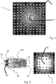
- Fig. 1a shows a setup for a prior art ring light illuminator 10 .
- An arc lamp 12 is used as a light source; light from the arc lamp 12 is coupled into plural optical fibres 11 by suitable optical elements 13 (only one such element is shown in the drawing).
- Ends 14 of the optical fibres 11 are arranged annularly in a ring shaped carrier 17 of the ring light illuminator 10 , in such a way that they emit the light from the arc lamp 12 towards a area 15 to be illuminated circumscribed by the carrier 17 .
- the cones 16 the light is emitted from the ends 14 with a considerable divergence, meaning a divergence too large for many precision applications.
- Fig. 1b shows another setup for a prior art ring illuminator 20 .
- plural light sources 22 are arranged in an annular fashion.
- the light sources 22 emit light towards an area 15 to be illuminated.
- the light sources are LEDs, which typically are provided with shaping optics (not shown) to concentrate the light emitted from the LEDs around a predefined direction.
- shaping optics not shown
- a ring light illuminator according to the invention has the same general setup as the prior art ring light illuminator shown; however, the prior art shaping optics are replaced with beam shapers according to the invention, of a configuration described below.
- Fig. 2 shows the intensity distribution 1 achievable with a ring illuminator 20 as described in the context of Fig 1b , comprising eight light sources with TIR lenses (see Fig. 3 ) as shaping optics.
- the illumination pattern is rather diffuse.
- the central region of the image shown is only moderately brighter than the regions illuminated by one of the cones 26 , indicating that a considerable amount of intensity is directed towards off-centre regions of the area shown in the image rather than towards the central area 15 to be illuminated.
- the intensity distribution achievable with a ring illuminator 10 as described in the context of Fig. 1a is similar.
- Fig. 3 shows a TIR (total internal reflection) lens 23 .
- Light indicated by light rays 100 , from a light source 22 , which here is an LED, is captured by the TIR lens 23 and directed towards a spot 110 .
- Directing the light is achieved by two principles: A refractive lens portion 24 occupying a central part of the TIR lens 23 directs light rays 100 towards the spot 110 by refraction.
- Light rays 100 not hitting the refractive lens portion 24 , but captured by the TIR lens 23 are directed towards the spot 110 by total internal reflection from a side surface 25 of the TIR lens 23 . Also shown in Fig.
- the intensity distribution 2 created by the TIR lens 23 is roughly Gaussian, so that there is maximum intensity in the centre of the spot 110 , but there are also wide regions around the centre in which the intensity tails off, i.e. there are no clearly defined edges of the spot 110 .
- a TIR lens 23 as described here can be used as shaping optics for a prior art ring illuminator 20 as described in the context of Fig. 1b .
- the intensity distribution 2 of the spot 110 without clearly defined edges is the reason why the intensity distribution 1 created by a cooperation of eight such combinations of light source 22 and TIR lens 23 is rather diffuse, as is evident from Fig. 2 .
- Fig. 4 shows an aspheric condenser lens 33 and light rays 100 .
- an emitter 32 of an LED is shown schematically.
- the aspheric condenser lens 33 captures light from the light source and directs it onto a spot 110 .
- Directly imaging the LED emitter 32 as in this case introduces high non-uniformity risks of the illumination of spot 110 . Therefore the homogeneity of the intensity distribution created in an area to be illuminated by a ring light illuminator 20 of the type shown in Fig.
- Fig. 5 shows a compound lens 40 comprising a hemisphere lens 41 to collect light, indicated by light rays 100 , from a light source 42 , and a relay lens 43 , which directs the light onto a spot 110 . Also shown in Fig. 5 is the intensity distribution 4 of the spot 110 on a surface perpendicular to an optical axis 19 of the compound lens 40 , which is an image of the flat back surface of the hemisphere lens 41 , which is facing the light source 42 .
- Such a setup has a lower light collection efficiency than a TIR lens 23 as described in Fig. 3 , and is incompatible with encapsulated LEDs, which is a disadvantage in the assembly of an optical system like the ring light illuminator 20 of Fig. 1b .
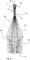
- Fig. 6 shows a beam shaper 50 comprising a light collector 60 , a homogenizing rod 70 , a cone section 52 , and a lens 80 .
- a light source (not shown) is inserted in the light collector 60 and emits light indicated by the light rays 100 .
- the light collector 60 collects light from the light source and directs it into the homogenizing rod 70 , through a first end 71 of the homogenizing rod 70 .
- the light is homogenized by reflection, typically multiple reflection, from the side surfaces 73 of the homogenizing rod.
- the beam shaper 50 is manufactured as one piece from a material that is transparent for the wavelengths of light the beam shaper is intended to be used with, like for example a plastic material or glass, and the reflection from the side surfaces 73 is total internal reflection.
- the light exits the homogenizing rod 70 through a second end 72 of the homogenizing rod 70 , and enters the cone section 52 . From there it reaches the lens 80 , which directs the light onto a spot 110 .
- the intensity distribution of the spot 110 is an image of the second end 72 of the homogenizing rod 70 .
- the purpose of the cone section 52 is to establish a fixed distance between the second end 72 of the homogenizing rod 70 and the lens 80 .
- the beam shaper 50 is manufactured as one piece, no alignment of individual components, i.e. of light collector 60 , homogenizing rod 70 , and lens 80 , is necessary during assembly of an optical system. This simplifies handling of the beam shaper 50 , and the assembly of optical systems, like for instance a ring light illuminator 20 , of the type shown in Fig. 1b ; contrary to prior art, however, beam shapers 50 just discussed, rather than TIR lenses, are used as shaping optics in embodiments of ring light illuminators according to the invention.
- the beam shaper 50 can of course also be used for other illumination tasks and is not limited to ring light illumination.
- Fig. 7 shows the intensity distribution 5 of the spot 110 created by the beam shaper 50 of Fig. 6 on a surface perpendicular to an optical axis 19 of the beam shaper 50 .
- the shape of the spot 110 is determined by the cross section of the homogenizing rod 70 , more precisely its cross section at the second end 72 . In the embodiment shown, this cross section has an octagonal shape. As has already been mentioned, different shapes of the cross section are also possible. It should be noted that the spot 110 exhibits clearly defined edges, and, due to the effect of the homogenizing rod 70 , the illumination intensity across the spot 110 is sufficiently homogeneous even for high precision applications.
- Fig. 8 shows the intensity distribution 6 achievable with a ring illuminator according to the invention, which, in the embodiment this figure relates to, comprises eight beam shapers 50 of the type described in the context of Fig. 6 as shaping optics. This figure should be compared with Fig. 2 . Due to the clearly defined edges of the light beams created by the beam shapers 50 , which result in the clearly defined edges of the spots 110 shown in Fig. 7 , in Fig. 8 , the area 15 to be illuminated is distinctly brighter than its surroundings.
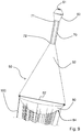
- Fig. 9 shows a perspective view of a beam shaper 50 according to the invention, as has already been shown in Fig. 6 .
- the light collector 60 exhibits a cavity 61 into which a light source (not shown) is to be introduced.
- the general configuration of the light collector 60 corresponds to that of a TIR lens 23 , as shown in Fig. 3 .
- the diameter 82 of lens 80 for imaging regulates the number of beam shapers 50 arranged in the ring-illuminator 20 .
- the lens 80 has an exit surface 84 that images the light exiting the homogenizing rod 70 through the second end 72 of the homogenizing rod 70 onto a spot 110. It is recommended that the exit surface 84 of the lens 80 for imaging is aspheric.
- Figs. 10a and 10b are perspective views of a light collector 60 as used for a beam shaper 50 according to the invention, as shown in Figs. 6 and 9 , as well as in shaping optics for a ring light illuminator according to the invention, which may be composed of several pieces. Only a part of the homogenizing rod 70 attached to the light collector 60 is shown.
- the rod 70 here has a hexagonal cross section, and the shape of the light collector 60 is adapted to the cross section of the rod 70 , also exhibiting a hexagonal cross section in a section adjacent to the first end 71 of the rod 70 .
- Fig. 10b clearly shows the cavity 61 of the light collector 60 , into which a light source (not shown), typically an LED, is to be inserted.
- Fig. 11 shows a sectional view of a light collector 60 and part of a homogenizing rod 70 .
- a LED 62 is introduced in the cavity 61 of the light collector 60 .
- the light collector 60 exhibits a refractive lens portion 64 , which collects light emitted into a central region around an optical axis 66 .
- the cross section of this region is determined by the shape and size of the refractive lens portion 64 .
- Light emitted by the LED into a region outside the central region is directed into the homogenizing rod 70 by total internal reflection from a side surface 65 of the light collector 60 .
- Fig. 12 is a top view of the cavity 61 in a light collector 60 , into which a light source like the LED 62 in Fig. 11 is to be inserted.
- the cavity 61 and the refractive lens portion 64 have an hexagonal cross section.
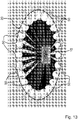
- Fig. 13 is an embodiment of a possible implementation of a plurality of beam shapers 50 arranged in ring to form the ring-illuminator 20 according to the invention.
- the plurality of beam shapers 50 arranged in the ring-illuminator 20 provides a homogeneous illumination for the area 15 to be illuminated.
- the diameter 82 of lens 80 (see Fig. 9 ) regulates the number of beam shapers 50 arranged in the ring-illuminator 20 .
- the diameter 82 of lens 80 is 30 mm, which results in approximately 24 beam shapers 50 arranged in the ring-illuminator 20 .
Description
- This patent application claims priority of
US provisional patent application No. 61/328,869 filed April 28, 2010 - The present invention relates to a ring light illuminator.
- The present invention also relates to a beam shaper.
- In many optical inspection or imaging tasks a well-defined illumination of the area to be inspected or imaged is required. For many such illumination purposes ring lights are used, for example in microscopy, where they are a common means to provide a dark field illumination. In such applications, it is desirable to restrict the area illuminated to the area of interest, and to have a homogeneous distribution of light within the area of interest. Possible light sources for example are arc lamps, LEDs (light emitting diodes), laser diodes, and halogen bulbs. While arc lamps typically provide higher light intensities than LEDs, they also exhibit stronger intensity fluctuations and shorter life times than LEDs; thus generally LEDs are a preferred choice of light source. As light from typical LEDs is emitted into a hemisphere around the LED, optical elements are required to direct as much as possible of the emitted light from one or plural LEDs into the area of interest, i.e. into the area to be illuminated.
- The European Patent Application
EP 1 919 001 A1 relates to a spot light device for product inspection, wherein a LED is used as light source. In order to homogenize the distribution of light across a certain area, the light from the LED is passed through a rod lens. The light from the LED is introduced into the rod lens by a condensing lens. In order to assure proper alignment of rod lens and condensing lens, and also in order to reduce the number of individual parts to be handled during assembly of an optical system, the rod lens and condensing lens are provided as sections of an optical unit, the rod lens constituting a light transmitting section and the condensing lens a light condensing section. The condensing section combines refraction and reflection in order to direct light from the light source into the transmitting section. - The European
Patent Application EP 2 177 816 A2 discloses an array of light sources, in particular LEDs, the light of which is directed into a light integrator shaped as a rod. The light integrator homogenizes and constrains the light, based on reflection of the light within the integrator. The light integrator may be a hollow tube with reflective inner surface or a solid rod of an optically transparent material, where the reflection of light within the light integrator is due to total internal reflection. The cross-section of the light integrator may be circular, polygonal, or irregular. Further optical elements may be provided downstream from the light integrator. To each of the light sources there may correspond an optical element for controlling and directing the light from the light source. The light integrator may be tapered, in order to influence the divergence of the light exiting from the light integrator. - The European
Patent Application EP 1 150 154 A1 discloses an illumination system, in particular for microscopes, wherein plural light sources, preferentially LEDs, are arranged in an annular carrier. The LEDs may be controlled individually or in groups, and exhibit a small angle of emission. - The German Patent Application
DE 28 52 203 discloses an illumination setup for a microscope, where light from a light source is guided along optical fibres and exits the fibres at a respective end of the fibres, wherein these respective ends are arranged in an annular fashion. A further ring illumination system, based on optical fibres is for example disclosed in the Germanpatent application DE 40 16 264 . -
Japanese Patent Specification no.2007/033852 - Published
US Patent Application no. 2005/237764 relates to a compact, high-brightness, integrated illuminator in which collection of light from a point-arc source is maximized by a multi-curvature reflector section configuration of elliptical reflector and segmented spherical retroreflector directing all light rays into a well-defined numerical aperture. - Published
US Patent Application no. 2007/285644 relates to an illumination system for a microlithographic projection exposure apparatus. The system comprises a masking device and a masking objective which projects the masking device onto an image plane. The illumination system further includes an optical correction element having a surface that is either aspherically shaped or supports diffractive structures that have at least substantially the effect of an aspherical surface. - Published
US Patent Application no. 2008/210953 relates to a luminaire with a plurality of light-emitting diodes in a decentralized arrangement. To improve the light emission pattern issued by the luminaire, the emission region defined by the light guide emission ends is smaller than the arrangement region defined by the totality of the light-emitting diodes. - A problem of ring illumination systems based on optical fibres is the large divergence of the light exiting an optical fibre. Likewise, annular arrangements of LEDs tend to create rather inhomogeneous illumination fields, and even if such LEDs are used in combination with state of the art collector lenses, the degree of homogeneity of the illumination field required for some applications is not achievable.
- Maximum light intensity is a very important design parameter for ring lights, as these inherently are "dark field" illumination, where scattered light is often a viewing object. A main disadvantage of LEDs compared to arc lamps (a standard for bright illumination for normal microscope viewing), is that they are typically dimmer. It is often the case, that LED based systems do not provide adequate light intensity at the viewed object, and that extreme care in design should be made to maximize the possible light at the image. Maximizing the light is particularly important in machine vision/ inspection where integration time cannot be arbitrarily lengthened to increase the light energy available to create a well exposed image. Increase of the integration time in a machine vision system decreases the frequency of images and increases the total inspection time (image time). Since the value of an inspection machine depends on how many fields can be imaged in a fixed time, maximizing the light at the object is a very important feature.
- A first aspect of the present invention provides a beam shaper as recited in
claim 1. - A second aspect of the present invention provides a ring light illuminator as recited in claim 7.
- The nature and mode of operation of the present invention will now be more fully described in the following detailed description of the invention taken with the accompanying drawing figures, in which
- Figure la shows a prior art ring light illuminator with annularly arranged ends of optical fibres;
-
Figure 1b shows a prior art ring light illuminator with annularly arranged light sources; -
Figure 2 shows the intensity distribution achievable with a prior art ring light illuminator as shown in figure lb; -
Figure 3 shows a TIR lens and light rays as well as the intensity distribution created by it on a surface; -
Figure 4 shows an aspheric condenser lens and light rays as well as the intensity distribution created by it on a surface; -
Figure 5 shows a compound lens and light rays as well as the intensity distribution created by it on a surface; -
Figure 6 shows a beam shaper according to the invention and light rays; -
Figure 7 shows the intensity distribution created on a surface by the beam shaper offigure 6 ; -
Figure 8 shows the intensity distribution achievable with a ring light illuminator according to the invention; -
Figure 9 is a perspective view of a beam shaper according to the invention; -
Figure 10a is a perspective view of a light collector and a homogenizing rod; -
Figure 10b is another perspective view of the light collector and the homogenizing rod offigure 10a ; -
Figure 11 shows a light source introduced into a cavity in a light collector with a homogenizing rod; -
Figure 12 is a top view of the cavity in a light collector; and -
Figure 13 is an embodiment of a possible implementation of a plurality of beam shapers arranged in ring to constitute the ring-illuminator according to the invention. - Same reference numerals refer to same elements throughout the various figures. Furthermore, only reference numerals necessary for the description of the respective figure are shown in the figures. The shown embodiments represent only examples of how the invention can be carried out. This should not be regarded as limiting the invention.
-
Fig. 1a shows a setup for a prior art ringlight illuminator 10. Anarc lamp 12 is used as a light source; light from thearc lamp 12 is coupled into pluraloptical fibres 11 by suitable optical elements 13 (only one such element is shown in the drawing). Ends 14 of theoptical fibres 11 are arranged annularly in a ring shapedcarrier 17 of thering light illuminator 10, in such a way that they emit the light from thearc lamp 12 towards aarea 15 to be illuminated circumscribed by thecarrier 17. As is indicated by thecones 16, the light is emitted from theends 14 with a considerable divergence, meaning a divergence too large for many precision applications. -
Fig. 1b shows another setup for a priorart ring illuminator 20. In anannular carrier 27plural light sources 22 are arranged in an annular fashion. Thelight sources 22 emit light towards anarea 15 to be illuminated. The light sources are LEDs, which typically are provided with shaping optics (not shown) to concentrate the light emitted from the LEDs around a predefined direction. As indicated by thecone 26, despite the shaping optics the light from a single light source exhibits a divergence that is too large for many precision applications. A ring light illuminator according to the invention has the same general setup as the prior art ring light illuminator shown; however, the prior art shaping optics are replaced with beam shapers according to the invention, of a configuration described below. -
Fig. 2 shows theintensity distribution 1 achievable with aring illuminator 20 as described in the context ofFig 1b , comprising eight light sources with TIR lenses (seeFig. 3 ) as shaping optics. The illumination pattern is rather diffuse. The central region of the image shown is only moderately brighter than the regions illuminated by one of thecones 26, indicating that a considerable amount of intensity is directed towards off-centre regions of the area shown in the image rather than towards thecentral area 15 to be illuminated. The intensity distribution achievable with aring illuminator 10 as described in the context ofFig. 1a is similar. -
Fig. 3 shows a TIR (total internal reflection)lens 23. Light, indicated bylight rays 100, from alight source 22, which here is an LED, is captured by theTIR lens 23 and directed towards aspot 110. Directing the light is achieved by two principles: Arefractive lens portion 24 occupying a central part of theTIR lens 23 directslight rays 100 towards thespot 110 by refraction.Light rays 100 not hitting therefractive lens portion 24, but captured by theTIR lens 23, are directed towards thespot 110 by total internal reflection from aside surface 25 of theTIR lens 23. Also shown inFig. 3 is theintensity distribution 2 of thespot 110 on a surface perpendicular to anoptical axis 19 of theTIR lens 23. Theintensity distribution 2 created by theTIR lens 23 is roughly Gaussian, so that there is maximum intensity in the centre of thespot 110, but there are also wide regions around the centre in which the intensity tails off, i.e. there are no clearly defined edges of thespot 110. ATIR lens 23 as described here can be used as shaping optics for a priorart ring illuminator 20 as described in the context ofFig. 1b . Theintensity distribution 2 of thespot 110 without clearly defined edges is the reason why theintensity distribution 1 created by a cooperation of eight such combinations oflight source 22 andTIR lens 23 is rather diffuse, as is evident fromFig. 2 . -
Fig. 4 shows anaspheric condenser lens 33 andlight rays 100. As light source in this figure anemitter 32 of an LED is shown schematically. Theaspheric condenser lens 33 captures light from the light source and directs it onto aspot 110. Also shown inFig. 4 is theintensity distribution 3 of thespot 110 on a surface perpendicular to anoptical axis 19 of thecondenser lens 33, which is an image of theLED light emitter 32. Directly imaging theLED emitter 32 as in this case introduces high non-uniformity risks of the illumination ofspot 110. Therefore the homogeneity of the intensity distribution created in an area to be illuminated by aring light illuminator 20 of the type shown inFig. 1b , with LEDs as light sources andaspheric condenser lenses 33 as shaping optics is not guaranteed to be sufficient for precision applications. Furthermore, typically the light collection efficiency of anaspheric condenser lens 33 as shown inFig. 4 is lower than the light collection efficiency of aTIR lens 23 as shown inFig. 3 . -
Fig. 5 shows acompound lens 40 comprising ahemisphere lens 41 to collect light, indicated bylight rays 100, from alight source 42, and arelay lens 43, which directs the light onto aspot 110. Also shown inFig. 5 is theintensity distribution 4 of thespot 110 on a surface perpendicular to anoptical axis 19 of thecompound lens 40, which is an image of the flat back surface of thehemisphere lens 41, which is facing thelight source 42. Such a setup has a lower light collection efficiency than aTIR lens 23 as described inFig. 3 , and is incompatible with encapsulated LEDs, which is a disadvantage in the assembly of an optical system like thering light illuminator 20 ofFig. 1b . -
Fig. 6 shows abeam shaper 50 comprising alight collector 60, a homogenizingrod 70, acone section 52, and alens 80. A light source (not shown) is inserted in thelight collector 60 and emits light indicated by the light rays 100. Thelight collector 60 collects light from the light source and directs it into the homogenizingrod 70, through afirst end 71 of the homogenizingrod 70. In the homogenizingrod 70 the light is homogenized by reflection, typically multiple reflection, from the side surfaces 73 of the homogenizing rod. Thebeam shaper 50 is manufactured as one piece from a material that is transparent for the wavelengths of light the beam shaper is intended to be used with, like for example a plastic material or glass, and the reflection from the side surfaces 73 is total internal reflection. The light exits the homogenizingrod 70 through asecond end 72 of the homogenizingrod 70, and enters thecone section 52. From there it reaches thelens 80, which directs the light onto aspot 110. The intensity distribution of thespot 110 is an image of thesecond end 72 of the homogenizingrod 70. The purpose of thecone section 52 is to establish a fixed distance between thesecond end 72 of the homogenizingrod 70 and thelens 80. As thebeam shaper 50 is manufactured as one piece, no alignment of individual components, i.e. oflight collector 60, homogenizingrod 70, andlens 80, is necessary during assembly of an optical system. This simplifies handling of thebeam shaper 50, and the assembly of optical systems, like for instance aring light illuminator 20, of the type shown inFig. 1b ; contrary to prior art, however,beam shapers 50 just discussed, rather than TIR lenses, are used as shaping optics in embodiments of ring light illuminators according to the invention. Thebeam shaper 50 can of course also be used for other illumination tasks and is not limited to ring light illumination. -
Fig. 7 shows theintensity distribution 5 of thespot 110 created by thebeam shaper 50 ofFig. 6 on a surface perpendicular to anoptical axis 19 of thebeam shaper 50. The shape of thespot 110 is determined by the cross section of the homogenizingrod 70, more precisely its cross section at thesecond end 72. In the embodiment shown, this cross section has an octagonal shape. As has already been mentioned, different shapes of the cross section are also possible. It should be noted that thespot 110 exhibits clearly defined edges, and, due to the effect of the homogenizingrod 70, the illumination intensity across thespot 110 is sufficiently homogeneous even for high precision applications. -
Fig. 8 shows theintensity distribution 6 achievable with a ring illuminator according to the invention, which, in the embodiment this figure relates to, comprises eightbeam shapers 50 of the type described in the context ofFig. 6 as shaping optics. This figure should be compared withFig. 2 . Due to the clearly defined edges of the light beams created by thebeam shapers 50, which result in the clearly defined edges of thespots 110 shown inFig. 7 , inFig. 8 , thearea 15 to be illuminated is distinctly brighter than its surroundings. -
Fig. 9 shows a perspective view of abeam shaper 50 according to the invention, as has already been shown inFig. 6 . Herelight rays 100 exiting thelens 80 are shown. The configuration of such abeam shaper 50 has already been discussed in the context ofFig. 6 . Thelight collector 60 exhibits acavity 61 into which a light source (not shown) is to be introduced. The general configuration of thelight collector 60 corresponds to that of aTIR lens 23, as shown inFig. 3 . Thediameter 82 oflens 80 for imaging regulates the number ofbeam shapers 50 arranged in the ring-illuminator 20. Thelens 80 has anexit surface 84 that images the light exiting the homogenizingrod 70 through thesecond end 72 of the homogenizingrod 70 onto aspot 110. It is recommended that theexit surface 84 of thelens 80 for imaging is aspheric. -
Figs. 10a and 10b are perspective views of alight collector 60 as used for abeam shaper 50 according to the invention, as shown inFigs. 6 and9 , as well as in shaping optics for a ring light illuminator according to the invention, which may be composed of several pieces. Only a part of the homogenizingrod 70 attached to thelight collector 60 is shown. Therod 70 here has a hexagonal cross section, and the shape of thelight collector 60 is adapted to the cross section of therod 70, also exhibiting a hexagonal cross section in a section adjacent to thefirst end 71 of therod 70.Fig. 10b clearly shows thecavity 61 of thelight collector 60, into which a light source (not shown), typically an LED, is to be inserted. -
Fig. 11 shows a sectional view of alight collector 60 and part of a homogenizingrod 70. ALED 62 is introduced in thecavity 61 of thelight collector 60. Analogous to theTIR lens 23 ofFig. 3 , thelight collector 60 exhibits arefractive lens portion 64, which collects light emitted into a central region around anoptical axis 66. The cross section of this region is determined by the shape and size of therefractive lens portion 64. Light emitted by the LED into a region outside the central region is directed into the homogenizingrod 70 by total internal reflection from aside surface 65 of thelight collector 60. -
Fig. 12 is a top view of thecavity 61 in alight collector 60, into which a light source like theLED 62 inFig. 11 is to be inserted. Thecavity 61 and therefractive lens portion 64 have an hexagonal cross section. -
Fig. 13 is an embodiment of a possible implementation of a plurality ofbeam shapers 50 arranged in ring to form the ring-illuminator 20 according to the invention. The plurality ofbeam shapers 50 arranged in the ring-illuminator 20 provides a homogeneous illumination for thearea 15 to be illuminated. Thediameter 82 of lens 80 (seeFig. 9 ) regulates the number ofbeam shapers 50 arranged in the ring-illuminator 20. In the embodiment shown here, thediameter 82 oflens 80 is 30 mm, which results in approximately 24beam shapers 50 arranged in the ring-illuminator 20. - The invention has been described with reference to specific embodiments. It is obvious to a person skilled in the art, however, that alterations and modifications can be made without leaving the scope of the subsequent claims.
-
- 1, 6
- intensity distribution
- 2, 3, 4, 5
- intensity distribution
- 10, 20
- ring light illuminator
- 11
- optical fibre
- 12
- arc lamp
- 13
- optical element
- 14
- end of optical fibre
- 15
- area to be illuminated
- 16, 26
- cone of light
- 17,27
- carrier
- 19, 66
- optical axis
- 22, 42
- light source
- 23
- TIR lens
- 24, 64
- refractive lens portion
- 25, 65
- side surface
- 32
- LED emitter
- 33
- aspheric condenser lens
- 40
- compound lens
- 41
- hemisphere lens
- 43
- relay lens
- 50
- beam shaper
- 52
- cone section
- 60
- light collector
- 61
- cavity
- 62
- LED
- 70
- homogenizing rod
- 71
- first end of homogenizing rod
- 72
- second end of homogenizing rod
- 73
- side surface of homogenizing rod
- 80
- lens
- 82
- diameter of lens
- 84
- exit surface
- 100
- light ray
- 110
- spot
Claims (9)
- Beam shaper (50) comprising:a light collector (60), a homogenizing rod (70), a cone section (52), and a lens (80),wherein said light collector (60) is configured to collect light from a light source inserted in said light collector (60) and direct it into said homogenizing rod (70) through a first end (71) thereof;wherein said light is homogenized by total internal reflection from the side surfaces (73) of said homogenizing rod (70),wherein said beam shaper (50) is manufactured as one piece from a material that is transparent for the wavelengths of light that the beam shaper is intended to be used with, wherein said light exits said homogenizing rod (70) through a second end (72) thereof and enters said cone section (52), from where it reaches said lens (80), which directs said light onto a spot (110), whose intensity distribution is an image of the second end (72);and wherein said cone section (52) establishes a fixed distance between the second end (72) and the lens (80).
- Beam shaper of claim 1, wherein the imaging lens (80) has an aspheric exit surface (84).
- Beam shaper of claim 1, wherein it is molded from a plastic material or is made of glass.
- Beam shaper of claim 1, wherein the homogenizing rod is a solid piece of matter, transparent at least for the wavelengths of light to be used for illumination and provided with a reflective coating.
- Beam shaper of claim 1, wherein the homogenizing rod (70) is a hollow tube with reflective inner walls.
- Beam shaper of claim 1, wherein the cross section of the homogenizing rod (70) perpendicular to the optical axis of the beam shaper is circular, elliptical, triangular, square, rectangular, hexagonal or octagonal.
- Ring light illuminator comprising a plurality of annularly arranged light sources, and further comprises the beam shaper as defined in any one of the claims 1-6, assigned to each light source.
- Ring light illuminator of claim 7, wherein each light source comprises at least one light emitting diode (LED).
- Ring light illuminator of claim 7, wherein the ring light illuminator exhibits plural cooling fins.
Applications Claiming Priority (2)
| Application Number | Priority Date | Filing Date | Title |
|---|---|---|---|
| US32886910P | 2010-04-28 | 2010-04-28 | |
| PCT/IB2011/051867 WO2011135534A2 (en) | 2010-04-28 | 2011-04-28 | Ring light illuminator and beam shaper for ring light illuminator |
Publications (3)
| Publication Number | Publication Date |
|---|---|
| EP2564111A2 EP2564111A2 (en) | 2013-03-06 |
| EP2564111A4 EP2564111A4 (en) | 2017-08-30 |
| EP2564111B1 true EP2564111B1 (en) | 2022-01-05 |
Family
ID=44861974
Family Applications (1)
| Application Number | Title | Priority Date | Filing Date |
|---|---|---|---|
| EP11774522.4A Active EP2564111B1 (en) | 2010-04-28 | 2011-04-28 | Ring light illuminator and beam shaper for ring light illuminator |
Country Status (7)
| Country | Link |
|---|---|
| US (1) | US8807813B2 (en) |
| EP (1) | EP2564111B1 (en) |
| JP (2) | JP2013525856A (en) |
| KR (1) | KR101765974B1 (en) |
| CN (1) | CN102859265B (en) |
| SG (1) | SG184961A1 (en) |
| WO (1) | WO2011135534A2 (en) |
Families Citing this family (12)
| Publication number | Priority date | Publication date | Assignee | Title |
|---|---|---|---|---|
| JP5589007B2 (en) | 2012-01-18 | 2014-09-10 | シャープ株式会社 | Light emitting device, lighting device, and vehicle headlamp |
| US9291877B2 (en) * | 2012-11-15 | 2016-03-22 | Og Technologies, Inc. | Method and apparatus for uniformly focused ring light |
| JP2014170034A (en) * | 2013-03-01 | 2014-09-18 | Panasonic Corp | Image display device |
| JP6177596B2 (en) | 2013-06-18 | 2017-08-09 | シャープ株式会社 | Light emitting device |
| US9599572B2 (en) | 2014-04-07 | 2017-03-21 | Orbotech Ltd. | Optical inspection system and method |
| ES2958398T3 (en) | 2015-01-23 | 2024-02-08 | Bayer Ag | Procedure and device to determine the effect of active substances on nematodes and other organisms in aqueous tests |
| DE102015209455A1 (en) * | 2015-05-22 | 2016-11-24 | Sac Sirius Advanced Cybernetics Gmbh | Apparatus and method for the optical detection of inner walls |
| JP6305967B2 (en) * | 2015-11-11 | 2018-04-04 | シャープ株式会社 | Light emitting device, lighting device, and vehicle headlamp |
| US10591648B2 (en) * | 2016-06-01 | 2020-03-17 | Arlo Technologies, Inc. | Camera with polygonal lens |
| CN107525016A (en) * | 2017-07-03 | 2017-12-29 | 重庆大学 | A kind of light reflecting device for improving architecture indoor lighting effect |
| CN111336414B (en) * | 2020-03-16 | 2022-04-08 | 广东省半导体产业技术研究院 | Design method of uniform light spot and illumination device of uniform light spot |
| CN114114679B (en) * | 2021-11-26 | 2024-04-05 | 中山大学 | Depth-control directional illumination display system and method |
Family Cites Families (25)
| Publication number | Priority date | Publication date | Assignee | Title |
|---|---|---|---|---|
| DE2852203C3 (en) | 1978-12-02 | 1982-03-11 | Ibm Deutschland Gmbh, 7000 Stuttgart | Light guide device for an imaging device operated with incident light |
| JPS62173643A (en) * | 1986-01-27 | 1987-07-30 | Hitachi Ltd | Optical information reproducing pickup |
| US4883333A (en) * | 1987-10-13 | 1989-11-28 | Yanez Serge J | Integrated, solid, optical device |
| JPH01269248A (en) * | 1988-04-20 | 1989-10-26 | Mitsubishi Electric Corp | Optical recording and reproducing device |
| DE4016264A1 (en) | 1990-05-19 | 1991-11-21 | Faseroptik Henning Gmbh & Co | FIBER OPTIC RING LIGHT |
| ATE235704T1 (en) * | 2000-04-26 | 2003-04-15 | Cobra Electronic Gmbh | ARRANGEMENT AND METHOD FOR RING-SHAPED ILLUMINATION, IN PARTICULAR FOR REFLECTED LIGHT ILLUMINATION IN MICROSCOPES |
| US6939009B2 (en) | 2001-02-06 | 2005-09-06 | Optics 1, Inc. | Compact work light with high illumination uniformity |
| JP2002296538A (en) * | 2001-03-29 | 2002-10-09 | Canon Inc | Illumination optical system, and projection type image display device using the same |
| JP4199478B2 (en) * | 2001-04-17 | 2008-12-17 | Hoya株式会社 | Endoscope illumination optical system |
| JP2003091045A (en) * | 2001-09-17 | 2003-03-28 | Mitsubishi Electric Corp | Lighting optical system and projection type display device |
| US7410283B2 (en) * | 2002-11-19 | 2008-08-12 | Den-Mat Holdings Llc | Dental light guide |
| JP5085127B2 (en) | 2003-07-23 | 2012-11-28 | トムソン ライセンシング | Illumination device with polarization recycling in a double prism |
| CN2639704Y (en) * | 2003-09-01 | 2004-09-08 | 东莞市星锐灯饰有限公司 | Lamp structure |
| US7101063B2 (en) | 2004-02-05 | 2006-09-05 | Hewlett-Packard Development Company, L.P. | Systems and methods for integrating light |
| US7390116B2 (en) * | 2004-04-23 | 2008-06-24 | Anvik Corporation | High-brightness, compact illuminator with integrated optical elements |
| US20070285644A1 (en) * | 2004-09-13 | 2007-12-13 | Carl Zeiss Smt Ag | Microlithographic Projection Exposure Apparatus |
| DE102005030374A1 (en) * | 2005-06-29 | 2007-01-04 | Zumtobel Staff Gmbh | Luminaire with a large number of light-emitting diodes in a decentralized arrangement |
| JP2007033852A (en) * | 2005-07-27 | 2007-02-08 | Chinontec Kk | Rod integrator and irradiating apparatus |
| FR2901345B1 (en) * | 2006-05-16 | 2008-07-18 | Valeo Vision Sa | LIGHTING AND / OR SIGNALING DEVICE FOR A MOTOR VEHICLE. |
| US7621638B2 (en) * | 2006-11-29 | 2009-11-24 | Clarity Medical Systems, Inc. | Delivering a short Arc lamp light for eye imaging |
| JP4855914B2 (en) * | 2006-12-04 | 2012-01-18 | シーシーエス株式会社 | Ring type lighting device |
| JP4511563B2 (en) * | 2007-02-13 | 2010-07-28 | 株式会社林創研 | microscope |
| JP3142994U (en) * | 2008-04-22 | 2008-07-03 | 株式会社渋谷光学 | Dark field illumination device |
| JP2010053276A (en) * | 2008-08-29 | 2010-03-11 | Oji Paper Co Ltd | Foaming composition and optical member made of foaming composition |
| US20100097802A1 (en) | 2008-10-20 | 2010-04-22 | Robe Lighting S.R.O. | Light collection system for an led luminaire |
-
2011
- 2011-04-28 US US13/376,249 patent/US8807813B2/en active Active
- 2011-04-28 SG SG2012078028A patent/SG184961A1/en unknown
- 2011-04-28 CN CN201180021092.6A patent/CN102859265B/en active Active
- 2011-04-28 KR KR1020127030733A patent/KR101765974B1/en active IP Right Grant
- 2011-04-28 WO PCT/IB2011/051867 patent/WO2011135534A2/en active Application Filing
- 2011-04-28 EP EP11774522.4A patent/EP2564111B1/en active Active
- 2011-04-28 JP JP2013506800A patent/JP2013525856A/en active Pending
-
2016
- 2016-01-14 JP JP2016005081A patent/JP6113872B2/en not_active Withdrawn - After Issue
Also Published As
| Publication number | Publication date |
|---|---|
| EP2564111A4 (en) | 2017-08-30 |
| SG184961A1 (en) | 2012-11-29 |
| KR20130059353A (en) | 2013-06-05 |
| WO2011135534A2 (en) | 2011-11-03 |
| US8807813B2 (en) | 2014-08-19 |
| JP6113872B2 (en) | 2017-04-12 |
| CN102859265A (en) | 2013-01-02 |
| CN102859265B (en) | 2015-04-22 |
| WO2011135534A3 (en) | 2012-01-19 |
| JP2016105190A (en) | 2016-06-09 |
| US20120087143A1 (en) | 2012-04-12 |
| KR101765974B1 (en) | 2017-08-07 |
| JP2013525856A (en) | 2013-06-20 |
| EP2564111A2 (en) | 2013-03-06 |
Similar Documents
| Publication | Publication Date | Title |
|---|---|---|
| EP2564111B1 (en) | Ring light illuminator and beam shaper for ring light illuminator | |
| US8926152B2 (en) | Ring light illuminator, beam shaper and method for illumination | |
| US8408772B2 (en) | LED illumination device | |
| US8125709B2 (en) | Illumination device, in particular for microscopes | |
| US9046241B2 (en) | High efficiency directional light source using lens optics | |
| US20100284201A1 (en) | Illuminator using non-uniform light sources | |
| US20100033970A1 (en) | Lighting Device with Variable Angle of Emission | |
| WO2011076213A1 (en) | Projecting illumination device with multiple light sources | |
| EP3366990B1 (en) | Led lamp | |
| JP6105805B2 (en) | Microscope with transmitted light illuminator for critical illumination | |
| US20110235360A1 (en) | Light source device for supplying light to fiber optic illumination system | |
| CN213577065U (en) | Light beam homogenizing device and light beam homogenizing stage lamp | |
| JP5881294B2 (en) | Luminous flux control member and optical apparatus provided with the same | |
| KR20190049457A (en) | An led lamp and a lighting device including the same | |
| JP2005214688A (en) | Light source device for inspection |
Legal Events
| Date | Code | Title | Description |
|---|---|---|---|
| PUAI | Public reference made under article 153(3) epc to a published international application that has entered the european phase |
Free format text: ORIGINAL CODE: 0009012 |
|
| 17P | Request for examination filed |
Effective date: 20121128 |
|
| AK | Designated contracting states |
Kind code of ref document: A2 Designated state(s): AL AT BE BG CH CY CZ DE DK EE ES FI FR GB GR HR HU IE IS IT LI LT LU LV MC MK MT NL NO PL PT RO RS SE SI SK SM TR |
|
| RIN1 | Information on inventor provided before grant (corrected) |
Inventor name: HILL, ANDY |
|
| DAX | Request for extension of the european patent (deleted) | ||
| A4 | Supplementary search report drawn up and despatched |
Effective date: 20170802 |
|
| RIC1 | Information provided on ipc code assigned before grant |
Ipc: F21V 5/00 20150101ALI20170727BHEP Ipc: G02B 21/08 20060101ALI20170727BHEP Ipc: F21W 131/406 20060101ALI20170727BHEP Ipc: F21V 8/00 20060101ALI20170727BHEP Ipc: F21V 29/00 20150101ALI20170727BHEP Ipc: G02B 21/10 20060101ALI20170727BHEP Ipc: G02B 27/09 20060101ALI20170727BHEP Ipc: G01N 21/88 20060101ALI20170727BHEP Ipc: F21Y 115/10 20160101ALI20170727BHEP Ipc: F21S 2/00 20160101AFI20170727BHEP |
|
| STAA | Information on the status of an ep patent application or granted ep patent |
Free format text: STATUS: EXAMINATION IS IN PROGRESS |
|
| 17Q | First examination report despatched |
Effective date: 20190426 |
|
| STAA | Information on the status of an ep patent application or granted ep patent |
Free format text: STATUS: EXAMINATION IS IN PROGRESS |
|
| GRAP | Despatch of communication of intention to grant a patent |
Free format text: ORIGINAL CODE: EPIDOSNIGR1 |
|
| STAA | Information on the status of an ep patent application or granted ep patent |
Free format text: STATUS: GRANT OF PATENT IS INTENDED |
|
| INTG | Intention to grant announced |
Effective date: 20210217 |
|
| GRAJ | Information related to disapproval of communication of intention to grant by the applicant or resumption of examination proceedings by the epo deleted |
Free format text: ORIGINAL CODE: EPIDOSDIGR1 |
|
| STAA | Information on the status of an ep patent application or granted ep patent |
Free format text: STATUS: EXAMINATION IS IN PROGRESS |
|
| INTC | Intention to grant announced (deleted) | ||
| GRAP | Despatch of communication of intention to grant a patent |
Free format text: ORIGINAL CODE: EPIDOSNIGR1 |
|
| STAA | Information on the status of an ep patent application or granted ep patent |
Free format text: STATUS: GRANT OF PATENT IS INTENDED |
|
| INTG | Intention to grant announced |
Effective date: 20210721 |
|
| GRAS | Grant fee paid |
Free format text: ORIGINAL CODE: EPIDOSNIGR3 |
|
| GRAA | (expected) grant |
Free format text: ORIGINAL CODE: 0009210 |
|
| STAA | Information on the status of an ep patent application or granted ep patent |
Free format text: STATUS: THE PATENT HAS BEEN GRANTED |
|
| AK | Designated contracting states |
Kind code of ref document: B1 Designated state(s): AL AT BE BG CH CY CZ DE DK EE ES FI FR GB GR HR HU IE IS IT LI LT LU LV MC MK MT NL NO PL PT RO RS SE SI SK SM TR |
|
| REG | Reference to a national code |
Ref country code: GB Ref legal event code: FG4D |
|
| REG | Reference to a national code |
Ref country code: CH Ref legal event code: EP |
|
| REG | Reference to a national code |
Ref country code: AT Ref legal event code: REF Ref document number: 1460899 Country of ref document: AT Kind code of ref document: T Effective date: 20220115 |
|
| REG | Reference to a national code |
Ref country code: DE Ref legal event code: R096 Ref document number: 602011072358 Country of ref document: DE |
|
| REG | Reference to a national code |
Ref country code: IE Ref legal event code: FG4D |
|
| REG | Reference to a national code |
Ref country code: NL Ref legal event code: FP |
|
| REG | Reference to a national code |
Ref country code: LT Ref legal event code: MG9D |
|
| REG | Reference to a national code |
Ref country code: AT Ref legal event code: MK05 Ref document number: 1460899 Country of ref document: AT Kind code of ref document: T Effective date: 20220105 |
|
| PG25 | Lapsed in a contracting state [announced via postgrant information from national office to epo] |
Ref country code: SE Free format text: LAPSE BECAUSE OF FAILURE TO SUBMIT A TRANSLATION OF THE DESCRIPTION OR TO PAY THE FEE WITHIN THE PRESCRIBED TIME-LIMIT Effective date: 20220105 Ref country code: RS Free format text: LAPSE BECAUSE OF FAILURE TO SUBMIT A TRANSLATION OF THE DESCRIPTION OR TO PAY THE FEE WITHIN THE PRESCRIBED TIME-LIMIT Effective date: 20220105 Ref country code: PT Free format text: LAPSE BECAUSE OF FAILURE TO SUBMIT A TRANSLATION OF THE DESCRIPTION OR TO PAY THE FEE WITHIN THE PRESCRIBED TIME-LIMIT Effective date: 20220505 Ref country code: NO Free format text: LAPSE BECAUSE OF FAILURE TO SUBMIT A TRANSLATION OF THE DESCRIPTION OR TO PAY THE FEE WITHIN THE PRESCRIBED TIME-LIMIT Effective date: 20220405 Ref country code: LT Free format text: LAPSE BECAUSE OF FAILURE TO SUBMIT A TRANSLATION OF THE DESCRIPTION OR TO PAY THE FEE WITHIN THE PRESCRIBED TIME-LIMIT Effective date: 20220105 Ref country code: HR Free format text: LAPSE BECAUSE OF FAILURE TO SUBMIT A TRANSLATION OF THE DESCRIPTION OR TO PAY THE FEE WITHIN THE PRESCRIBED TIME-LIMIT Effective date: 20220105 Ref country code: ES Free format text: LAPSE BECAUSE OF FAILURE TO SUBMIT A TRANSLATION OF THE DESCRIPTION OR TO PAY THE FEE WITHIN THE PRESCRIBED TIME-LIMIT Effective date: 20220105 Ref country code: BG Free format text: LAPSE BECAUSE OF FAILURE TO SUBMIT A TRANSLATION OF THE DESCRIPTION OR TO PAY THE FEE WITHIN THE PRESCRIBED TIME-LIMIT Effective date: 20220405 |
|
| PG25 | Lapsed in a contracting state [announced via postgrant information from national office to epo] |
Ref country code: PL Free format text: LAPSE BECAUSE OF FAILURE TO SUBMIT A TRANSLATION OF THE DESCRIPTION OR TO PAY THE FEE WITHIN THE PRESCRIBED TIME-LIMIT Effective date: 20220105 Ref country code: LV Free format text: LAPSE BECAUSE OF FAILURE TO SUBMIT A TRANSLATION OF THE DESCRIPTION OR TO PAY THE FEE WITHIN THE PRESCRIBED TIME-LIMIT Effective date: 20220105 Ref country code: GR Free format text: LAPSE BECAUSE OF FAILURE TO SUBMIT A TRANSLATION OF THE DESCRIPTION OR TO PAY THE FEE WITHIN THE PRESCRIBED TIME-LIMIT Effective date: 20220406 Ref country code: FI Free format text: LAPSE BECAUSE OF FAILURE TO SUBMIT A TRANSLATION OF THE DESCRIPTION OR TO PAY THE FEE WITHIN THE PRESCRIBED TIME-LIMIT Effective date: 20220105 Ref country code: AT Free format text: LAPSE BECAUSE OF FAILURE TO SUBMIT A TRANSLATION OF THE DESCRIPTION OR TO PAY THE FEE WITHIN THE PRESCRIBED TIME-LIMIT Effective date: 20220105 |
|
| PG25 | Lapsed in a contracting state [announced via postgrant information from national office to epo] |
Ref country code: IS Free format text: LAPSE BECAUSE OF FAILURE TO SUBMIT A TRANSLATION OF THE DESCRIPTION OR TO PAY THE FEE WITHIN THE PRESCRIBED TIME-LIMIT Effective date: 20220505 |
|
| REG | Reference to a national code |
Ref country code: DE Ref legal event code: R097 Ref document number: 602011072358 Country of ref document: DE |
|
| PG25 | Lapsed in a contracting state [announced via postgrant information from national office to epo] |
Ref country code: SM Free format text: LAPSE BECAUSE OF FAILURE TO SUBMIT A TRANSLATION OF THE DESCRIPTION OR TO PAY THE FEE WITHIN THE PRESCRIBED TIME-LIMIT Effective date: 20220105 Ref country code: SK Free format text: LAPSE BECAUSE OF FAILURE TO SUBMIT A TRANSLATION OF THE DESCRIPTION OR TO PAY THE FEE WITHIN THE PRESCRIBED TIME-LIMIT Effective date: 20220105 Ref country code: RO Free format text: LAPSE BECAUSE OF FAILURE TO SUBMIT A TRANSLATION OF THE DESCRIPTION OR TO PAY THE FEE WITHIN THE PRESCRIBED TIME-LIMIT Effective date: 20220105 Ref country code: EE Free format text: LAPSE BECAUSE OF FAILURE TO SUBMIT A TRANSLATION OF THE DESCRIPTION OR TO PAY THE FEE WITHIN THE PRESCRIBED TIME-LIMIT Effective date: 20220105 Ref country code: DK Free format text: LAPSE BECAUSE OF FAILURE TO SUBMIT A TRANSLATION OF THE DESCRIPTION OR TO PAY THE FEE WITHIN THE PRESCRIBED TIME-LIMIT Effective date: 20220105 Ref country code: CZ Free format text: LAPSE BECAUSE OF FAILURE TO SUBMIT A TRANSLATION OF THE DESCRIPTION OR TO PAY THE FEE WITHIN THE PRESCRIBED TIME-LIMIT Effective date: 20220105 |
|
| PLBE | No opposition filed within time limit |
Free format text: ORIGINAL CODE: 0009261 |
|
| STAA | Information on the status of an ep patent application or granted ep patent |
Free format text: STATUS: NO OPPOSITION FILED WITHIN TIME LIMIT |
|
| PG25 | Lapsed in a contracting state [announced via postgrant information from national office to epo] |
Ref country code: AL Free format text: LAPSE BECAUSE OF FAILURE TO SUBMIT A TRANSLATION OF THE DESCRIPTION OR TO PAY THE FEE WITHIN THE PRESCRIBED TIME-LIMIT Effective date: 20220105 |
|
| REG | Reference to a national code |
Ref country code: CH Ref legal event code: PL |
|
| 26N | No opposition filed |
Effective date: 20221006 |
|
| GBPC | Gb: european patent ceased through non-payment of renewal fee |
Effective date: 20220428 |
|
| REG | Reference to a national code |
Ref country code: BE Ref legal event code: MM Effective date: 20220430 |
|
| PG25 | Lapsed in a contracting state [announced via postgrant information from national office to epo] |
Ref country code: MC Free format text: LAPSE BECAUSE OF FAILURE TO SUBMIT A TRANSLATION OF THE DESCRIPTION OR TO PAY THE FEE WITHIN THE PRESCRIBED TIME-LIMIT Effective date: 20220105 Ref country code: LU Free format text: LAPSE BECAUSE OF NON-PAYMENT OF DUE FEES Effective date: 20220428 Ref country code: LI Free format text: LAPSE BECAUSE OF NON-PAYMENT OF DUE FEES Effective date: 20220430 Ref country code: GB Free format text: LAPSE BECAUSE OF NON-PAYMENT OF DUE FEES Effective date: 20220428 Ref country code: FR Free format text: LAPSE BECAUSE OF NON-PAYMENT OF DUE FEES Effective date: 20220430 Ref country code: CH Free format text: LAPSE BECAUSE OF NON-PAYMENT OF DUE FEES Effective date: 20220430 |
|
| PG25 | Lapsed in a contracting state [announced via postgrant information from national office to epo] |
Ref country code: SI Free format text: LAPSE BECAUSE OF FAILURE TO SUBMIT A TRANSLATION OF THE DESCRIPTION OR TO PAY THE FEE WITHIN THE PRESCRIBED TIME-LIMIT Effective date: 20220105 Ref country code: BE Free format text: LAPSE BECAUSE OF NON-PAYMENT OF DUE FEES Effective date: 20220430 |
|
| PG25 | Lapsed in a contracting state [announced via postgrant information from national office to epo] |
Ref country code: IE Free format text: LAPSE BECAUSE OF NON-PAYMENT OF DUE FEES Effective date: 20220428 |
|
| PGFP | Annual fee paid to national office [announced via postgrant information from national office to epo] |
Ref country code: NL Payment date: 20230426 Year of fee payment: 13 |
|
| P01 | Opt-out of the competence of the unified patent court (upc) registered |
Effective date: 20230525 |
|
| PG25 | Lapsed in a contracting state [announced via postgrant information from national office to epo] |
Ref country code: IT Free format text: LAPSE BECAUSE OF FAILURE TO SUBMIT A TRANSLATION OF THE DESCRIPTION OR TO PAY THE FEE WITHIN THE PRESCRIBED TIME-LIMIT Effective date: 20220105 |
|
| PGFP | Annual fee paid to national office [announced via postgrant information from national office to epo] |
Ref country code: DE Payment date: 20230427 Year of fee payment: 13 |
|
| PG25 | Lapsed in a contracting state [announced via postgrant information from national office to epo] |
Ref country code: HU Free format text: LAPSE BECAUSE OF FAILURE TO SUBMIT A TRANSLATION OF THE DESCRIPTION OR TO PAY THE FEE WITHIN THE PRESCRIBED TIME-LIMIT; INVALID AB INITIO Effective date: 20110428 |