EP2562809A2 - High performance liquid cooled heatsink for igbt modules - Google Patents
High performance liquid cooled heatsink for igbt modules Download PDFInfo
- Publication number
- EP2562809A2 EP2562809A2 EP12180184A EP12180184A EP2562809A2 EP 2562809 A2 EP2562809 A2 EP 2562809A2 EP 12180184 A EP12180184 A EP 12180184A EP 12180184 A EP12180184 A EP 12180184A EP 2562809 A2 EP2562809 A2 EP 2562809A2
- Authority
- EP
- European Patent Office
- Prior art keywords
- passages
- fins
- housing
- heat sink
- base plate
- Prior art date
- Legal status (The legal status is an assumption and is not a legal conclusion. Google has not performed a legal analysis and makes no representation as to the accuracy of the status listed.)
- Granted
Links
Images


Classifications
-
- H—ELECTRICITY
- H10—SEMICONDUCTOR DEVICES; ELECTRIC SOLID-STATE DEVICES NOT OTHERWISE PROVIDED FOR
- H10W—GENERIC PACKAGES, INTERCONNECTIONS, CONNECTORS OR OTHER CONSTRUCTIONAL DETAILS OF DEVICES COVERED BY CLASS H10
- H10W40/00—Arrangements for thermal protection or thermal control
- H10W40/40—Arrangements for thermal protection or thermal control involving heat exchange by flowing fluids
- H10W40/47—Arrangements for thermal protection or thermal control involving heat exchange by flowing fluids by flowing liquids, e.g. forced water cooling
-
- H—ELECTRICITY
- H05—ELECTRIC TECHNIQUES NOT OTHERWISE PROVIDED FOR
- H05K—PRINTED CIRCUITS; CASINGS OR CONSTRUCTIONAL DETAILS OF ELECTRIC APPARATUS; MANUFACTURE OF ASSEMBLAGES OF ELECTRICAL COMPONENTS
- H05K7/00—Constructional details common to different types of electric apparatus
- H05K7/20—Modifications to facilitate cooling, ventilating, or heating
- H05K7/20218—Modifications to facilitate cooling, ventilating, or heating using a liquid coolant without phase change in electronic enclosures
-
- H—ELECTRICITY
- H05—ELECTRIC TECHNIQUES NOT OTHERWISE PROVIDED FOR
- H05K—PRINTED CIRCUITS; CASINGS OR CONSTRUCTIONAL DETAILS OF ELECTRIC APPARATUS; MANUFACTURE OF ASSEMBLAGES OF ELECTRICAL COMPONENTS
- H05K7/00—Constructional details common to different types of electric apparatus
- H05K7/20—Modifications to facilitate cooling, ventilating, or heating
- H05K7/2089—Modifications to facilitate cooling, ventilating, or heating for power electronics, e.g. for inverters for controlling motor
- H05K7/20936—Liquid coolant with phase change
Landscapes
- Cooling Or The Like Of Electrical Apparatus (AREA)
- Cooling Or The Like Of Semiconductors Or Solid State Devices (AREA)
Abstract
Description
- The subject matter described herein relates generally to cooling an object and, more specifically, to extracting heat from an insulated gate bipolar transistor (IGBT) module.
- At least some known computer and/or electronic systems include at least one IGBT module for high-efficient, fast switching of electric power. During operation, known IGBT modules typically generate heat. As such, at least some known IGBT modules are coupled to a heat sink to dissipate heat generated by the IGBT module. At least some known systems have an IGBT module-heat sink interface with a high thermal resistance. For example, the interface may have micro-flatness issues and/or a lack of contact area due to low pressure.
- With recent technological developments in computer and/or electronic systems, considerable efforts have been made to develop heat sinks that are reliable and efficient. At least some known systems include a thermal interface material (TIM), such as zinc oxide filled silicone grease, disposed between the IGBT module and the heat sink. However, a thin grease joint of the TIM may still account for 25-50% of a total temperature drop between the interface and the ambient environment.
- In one aspect according to the present invention, a housing is provided for use with a heat sink including a plurality of fms. The housing includes a first manifold defining a plurality of first passages, and a second manifold defming a plurality of second passages in fluid communication with the plurality of first passages. At least one of the plurality of first passages extends between an adjacent pair of the plurality of second passages and is oriented to channel fluid toward at least one of the plurality of fins. The plurality of fins are positioned within the housing.
- In another aspect, a heat sink assembly is provided for use with an electronic device. The heat sink assembly includes a base plate coupled to a first side of the electronic device, a plurality of fins extending from the base plate, and a housing including a first manifold defining a plurality of first passages and a second manifold defining a plurality of second passages in fluid communication with the plurality of first passages. At least one of the plurality of first passages extends between an adjacent pair of the plurality of second passages and is oriented to channel fluid toward at least one of the plurality of fins. The plurality of fins are positioned within the housing.
- In yet another aspect, a method is provided for cooling an electronic device coupled to a heat sink assembly including a base plate and a plurality of fins extending from the base plate. The method includes positioning the plurality of fins within a housing including a first manifold defining a plurality of first passages and a second manifold defming a plurality of second passages in fluid communication with the plurality of first passages. At least one of the plurality of first passages extends between an adjacent pair of the plurality of second passages. Fluid is channeled through at least one of the plurality of first passages, toward at least one of the plurality of fins, and through at least one of the second plurality of second passages.
- Various features, functions, and advantages that have been discussed can be achieved independently in various embodiments of the present invention or may be combined in yet other embodiments further details of which can be seen with reference to the following description and drawings, in which:
-
FIG. 1 is a side view of an exemplary electronic device coupled to an exemplary heat sink and an exemplary housing; -
FIG. 2 is a top/bottom view of the heat sink shown inFIG. 1 ; and -
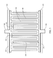
FIG. 3 is a schematic illustration of an exemplary arrangement of passages for the housing shown inFIG. 1 . - Various of the methods and systems described herein relate to cooling an object. A heat sink assembly includes a base plate coupled to a first side of the object, a plurality of fins extending from the base plate, and a housing comprising a first manifold defining a plurality of first passages and a second manifold defining a plurality of second passages in fluid communication with the plurality of first passages. During operation, heat is transferred from the object, through the base plate, and to the fins. To cool the fins, fluid is channeled through at least one of the first passages, toward at least one of the fins, and through at least one of the second passages.
-
FIG. 1 shows an exemplaryelectronic device 100 coupled to aheat sink assembly 110 including anexemplary heat sink 120 and anexemplary housing 130. As used herein, the term "electronic device" refers to an object that affects electrons and/or their associated fields and generates heat as a by-product of its operation. Examples of electronic devices include, without limitation, an insulated gate bipolar transistor (IGBT) module, a semiconductor chip, a microprocessor, a digital signal processor, a graphics processing unit, an integrated circuit, a diode, and/or any other suitable heat-generating device. In the exemplary embodiment,electronic device 100 is a Mitsubishi CM2400HCB-34N IGBT, commercially available from Mitsubishi Electric Corporation of Tokyo Japan. Alternatively,electronic device 100 may be any object that enablesheat sink 120 and/or housing 130 to function as described herein. - In the exemplary embodiment, a plurality of
electronic devices 100 are coupled toheat sink assembly 110. More specifically, in the exemplary embodiment,heat sink assembly 110 is double-sided to enable twoelectronic devices 100 to be coupled thereto. Alternatively, any quantity ofelectronic devices 100 may be coupled to aheat sink assembly 110 having any quantity of sides that enableselectronic device 100 and/orheat sink assembly 110 to function as described herein. - In the exemplary embodiment,
heat sink 120 includes abase plate 140 that is coupled toelectronic device 100 to absorb and/or dissipate heat generated byelectronic device 100.Heat sink 120 is coupled toelectronic device 100 using any suitable fastening mechanism that enablesheat sink assembly 110 and/orelectronic device 100 to function as described herein. For example, in the exemplary embodiment,base plate 140 andelectronic device 100 each have a plurality of openings (not shown inFIG. 1 ), and a fastener (not shown) extends through each opening to coupleelectronic device 100 and/orbase plate 140 to housing 130. Moreover, a thin solder interface is provided betweenbase plate 140 andelectronic device 100 to provide a thermal conductive material therebetween. In the exemplary embodiment, the thermal conductive material is a eutectic metal alloy. For example, in the exemplary embodiment, the eutectic metal alloy is used to solderbase plate 140 toelectronic device 100. In the exemplary embodiment, use of the eutectic metal alloy enablesbase plate 140 andelectronic device 100 to be intimately coupled to facilitate increasing a thermal conductivity therebetween. Alternatively, thermal conductive material may include any suitable material and/or composition that enablesheat sink 120 and/orelectronic device 100 to function as described herein. - To facilitate increasing thermal conductivity between
base plate 140 andelectronic device 100, in the exemplary embodiment,base plate 140 has asurface 150 that is substantially complementary to asurface 160 ofelectronic device 100. Additionally or alternatively,base plate 140 may be fabricated from a material having a high thermal conductivity such as, without limitation, aluminum, copper, aluminum silicon carbide, aluminum alloy, aluminum composite, copper alloy, copper composite, and/or graphite. In an alternative embodiment,heat sink assembly 110 does not includebase plate 140, andfins 170 are coupled directly toelectronic device surface 160. - In the exemplary embodiment, a plurality of
fins 170 extend frombase plate 140 to facilitate removing heat fromelectronic device 100. In the exemplary embodiment, eachfin 170 is integrally formed withbase plate 140. That is, in the exemplary embodiment,base plate 140 andfins 170 are fabricated from a single piece of metal, produced by extruding, casting, machining, and/or other metalworking process. - Additionally or alternatively,
fin 170 may be soldered tobase plate 140 at a temperature that is compatible withelectronic device 100. That is,fins 170 may be coupled tobase plate 140 without altering and/or damaging components (not shown) disposed withinelectronic device 100. For example, in such an embodiment, a eutectic metal bonding process is used to soft-solder fins 170 tobase plate 140. The eutectic metal bond provides low thermal impedance betweenfin 170 andbase plate 140. In the exemplary embodiment, the eutectic metal alloy has a melting temperature that is lower than a solder used inelectronic device 100. In the exemplary embodiment, the eutectic metal alloy has a melting temperature that is lower than approximately 360 °C. More particularly, in the exemplary embodiment, the eutectic metal alloy has a melting temperature that is lower than approximately 230 °C. Even more particularly, in the exemplary embodiment, the eutectic metal alloy has a melting temperature lower than approximately 180 °C.Table 1. Properties of Exemplary Solder Alloys Solder Alloy Element Ratio Thermal Conductivity at 25 °C (W/(m·K)) Melt Temperature (°C) AuSi 97/3 27 363 AuGe 88/12 44 356 AuSn 80/20 57 280 PbIn 80/20 17 280 (liquid) / 270 (solid) SnCu 99.3/0.7 65 227 SnCuNi N/A 64 227 SnAg 96.5/3.5 78 221 SnAgCu 95.6/3.5/0.9 -60 217 Eutectic SnAgCu 95.5/3.8/0.7 -60 -217-220 SnAgCuSb 96.2/2.5/0.8/0.5 57 215-217 PbIn 50/50 22 209 (liquid) / 180 (solid) SnPb 63/37 50 183 BiSn N/A 19 138 - In the exemplary embodiment, a solder alloy used to couple
fins 170 tobase plate 140 has a thermal conductivity between approximately 10.0 W/(m·K) and approximately 100.0 W/(m·K). Table 1 shows exemplary solder alloys that may be used to couple fins 170 tobase plate 140. Alternatively, the eutectic metal alloy may be any suitable material and/or composition that enablesheat sink 120 and/orelectronic device 100 to function as described herein. - In the exemplary embodiment,
fins 170 are fabricated from a material having a high thermal conductivity to facilitate increasing thermal conductivity betweenfins 170 andbase plate 140. Such materials include, without limitation, aluminum, copper, aluminum alloy, aluminum composite, copper alloy, copper composite, and/or graphite. In one embodiment, at least onefin 170 is generally solid to facilitate increasing a thermal conductivity offin 170. Additionally or alternatively,fins 170 may have a relatively large exterior surface area that is suitable to dissipate heat. For example, in the exemplary embodiment, eachfin 170 is substantially cylindrical, conical, and/or frustoconical, has a length between approximately 0.5 cm (0.20 in.) and approximately 2.5 cm (0.98 in.), and has a diameter between approximately 1.0 mm (0.04 in.) and approximately 4.0 mm (0.16 in.). Alternatively, eachfin 170 may have any size and/or shape that enablesfin 170 to function as described herein. - In the exemplary embodiment,
housing 130 is coupled tobase plate 140 to define acavity 180 therebetween.Housing 130 is coupled tobase plate 140 using any suitable fastening mechanism that enableshousing 130 and/orheat sink 120 to function as described herein. For example, in one embodiment, a collar extends about an outer periphery ofhousing 130 and/orbase plate 140 to provide a seal that enables fluid to be retained withincavity 180. In another embodiment,housing 130 andheat sink 120 have a complementary groove and ridge system that enables a similar function. In such an embodiment, the groove and ridge system is disposed around an outer periphery and under surface ofhousing 130 and/orbase plate 140 to provide a mating surface. A liquid seal such as, without limitation, an O-ring may be used with the collar and/or the groove and ridge system. - In the exemplary embodiment,
cavity 180 is sized to receivefins 170. In the exemplary embodiment,housing 130 includes a first or an inlet manifold and a second or an outlet manifold, described in more detail below, that include a plurality of first orinlet passages 190 and a plurality of second oroutlet passages 200, respectively. In the exemplary embodiment,inlet passages 190 are in fluid communication withoutlet passages 200 by way ofcavity 180. More specifically, in the exemplary embodiment, an arrangement of inlet andoutlet passages local flow paths 210 to be produced withincavity 180 to facilitate increasing heat transfer betweenpins 170 and fluid channeled throughcavity 180. For example, in the exemplary embodiment, eachinlet passage 190 is oriented to channel fluid toward anadjacent fin 170 and to anadjacent outlet passage 200. - During operation, in the exemplary embodiment,
electronic device 100 generates heat, which is absorbed byheat sink assembly 110. Withinheat sink assembly 110, heat transfers frombase plate 140 tofins 170 to enable heat to be transferred away fromelectronic device 100. - In the exemplary embodiment, fluid is channeled from
inlet passages 190 and towardbase plate 140 and/orfins 170 to enable heat to be transferred fromheat sink 120 or, more particularly,fins 170. Heat transfers fromfins 170 to the fluid, which is channeled towardoutlet passages 200. As such,heat sink assembly 110 produceslocal flow paths 210 that channel heat-transferred fluid away fromfins 170 to reduce an amount of heat transferred betweenfins 170. -
FIG. 2 showsheat sink 120 includingfins 170 that are closely spaced to increase an aggregate surface area offins 170 exposed to fluid channeled through cavity 180 (shown inFIG. 1 ). In the exemplary embodiment,fins 170 are arranged in an array and/or grid pattern. Alternatively,fins 170 may be arranged and/or oriented in any suitable configuration using an extrusion, casting, machining, and/or other metalworking process that enablesheat sink 120 to function as described herein. - In the exemplary embodiment, a plurality of
openings 220 extend throughbase plate 140.Openings 220 correspond to a plurality of openings (not shown) defined inelectronic device 100. As such, a fastener (not shown) may be extended therethrough to enableelectronic device 100 and/orbase plate 140 to be coupled tohousing 130. - Fluid exerts a static pressure within
cavity 180, and, in the exemplary embodiment, a plurality of stiffeningribs 230 extend across a portion ofbase plate 140 to provide structural support tobase plate 140. In the exemplary embodiment, stiffeningribs 230 provide flexural strength suitable to reduce deflection and/or deformation. In the exemplary embodiment, stiffeningribs 230 enable fluid to be channeled overfms 170. Moreover, in one embodiment, stiffeningribs 230 may be positioned and/or oriented to direct fluid throughcavity 180 between inlet passages 190 (shown inFIG. 1 ) and outlet passages 200 (shown inFIG. 1 ). - In the exemplary embodiment, a
seal 240 extends about an outer periphery ofbase plate 140.Seal 240 enables fluid to be retained withincavity 180. Alternatively, seal 240 may be positioned and/or oriented in any suitable configuration that enablesheat sink 120 and/or housing 130 (shown inFIG. 1 ) to function as described herein. -
FIG. 3 shows an arrangement of aninlet manifold 250 and anoutlet manifold 260 disposed within housing 130 (shown inFIG. 1 ). In the exemplary embodiment,inlet manifold 250 is in fluid communication withinlet passages 190 extending from afirst side wall 270 toward an opposingsecond side wall 280. In the exemplary embodiment, aninlet 290 is positioned and/or oriented to channel fluid throughinlet passages 190. - Moreover, in the exemplary embodiment,
outlet manifold 260 is in fluid communication withoutlet passages 200 extending fromsecond side wall 280 towardfirst side wall 270. In the exemplary embodiment,outlet passages 200 are positioned and/or oriented to channel fluid toward anoutlet 300. More specifically, in the exemplary embodiment, at least oneoutlet passage 200 extends between an adjacent pair ofinlet passages 190, and at least oneinlet passage 190 extends between an adjacent pair ofoutlet passages 200. That is, in the exemplary embodiment,inlet passage 190 andoutlet passages 200 are interleaved. In the exemplary embodiment, the interleaved arrangement ofpassages housing 130 such that heat transferred betweenfins 170 is substantially reduced as compared to conventional heat sinks. In the exemplary embodiment,inlet passages 190 andoutlet passages 200 are aligned to be substantially parallel to each other. - In the exemplary embodiment,
inlet manifold 250 is positioned and/or oriented to channel fluid towardoutlet manifold 260. In one embodiment, fluid has a higher pressure atinlet 290 such that fluid is pushed throughinlet passages 190,cavity 180, and/oroutlet passages 200. Additionally, fluid is at a lower pressure atoutlet 300 such that fluid is drawn frominlet passages 190,cavity 180, and/oroutlet passages 200. - In the exemplary embodiment, a
width 310 ofinlet passage 190, which is less than awidth 320 of outlet passage, is sized to enable fluid to be channeled substantially across alength 330 ofinlet passages 190. Alternatively, in one embodiment, eachinlet passage 190 may include a cover with a plurality of openings disposed alonglength 330. In such an embodiment, fluid channeled throughinlet passage 190 may be directed through the openings to enablefins 170 to be cooled. - The methods and systems described herein relate to cooling an electronic component using a heat sink assembly. The heat sink assembly includes fins that are disposed within a housing. The housing includes at least one manifold that is configured to direct fluid in local flow paths to provide a high turbulence and/or cooling efficiency for the heat sink assembly. As such, the local flow paths facilitate increasing a transfer of heat between the fins and fluid channeled through a cavity. Moreover, the heat sink assembly is designed to have a large surface area in contact with fluid coolant and/or in intimate thermal contact with an electronic device base plate to facilitate yielding high performance.
- Exemplary embodiments of cooling an electronic component are described above in detail. The methods and systems are not limited to the specific embodiments described herein, but rather, operations of the methods and components of the systems may be utilized independently and separately from other operations and/or components described herein. For example, the methods and apparatus described herein may have other industrial and/or consumer applications and are not limited to practice with electronic components as described herein. Rather, one or more embodiments may be implemented and utilized in connection with other industries.
- As used herein, an element or step recited in the singular and preceded with the word "a" or "an" should be understood as not excluding plural said elements or steps, unless such exclusion is explicitly stated. Further, references to "one embodiment" are not intended to be interpreted as excluding the existence of additional embodiments that also incorporate the recited features. Moreover, unless explicitly stated to the contrary, embodiments "comprising," "including," or "having" an element or a plurality of elements having a particular property may include additional such elements not having that property.
- This written description uses examples to disclose the invention, including the preferred mode, and also to enable any person skilled in the art to practice the invention, including making and using any devices or systems and performing any incorporated methods. The patentable scope of the invention is defined by the claims, and may include other examples that occur to those skilled in the art. Such other examples are intended to be within the scope of the claims if they have structural elements that do not differ from the literal language of the claims, or if they include equivalent structural elements with insubstantial differences from the literal language of the claims.
- Various aspects and embodiments of the present invention are defined by the following numbered clauses:
- 1. A housing for use with a heat sink including a plurality of fins, said housing comprising:
- a first manifold defining a plurality of first passages; and,
- a second manifold defining a plurality of second passages in fluid communication with the plurality of first passages, at least one of the plurality of first passages extending between an adjacent pair of the plurality of second passages and oriented to channel fluid toward at least one of the plurality of fins, wherein the plurality of fins are positioned within said housing.
- 2. A housing in accordance with clause 1, wherein the plurality of first passages and the plurality of second passages are oriented to provide a plurality of local flow paths within the housing.
- 3. A housing in accordance with any preceding clause, wherein said first manifold is in fluid communication with an inlet and said second manifold is in fluid communication with an outlet such that fluid is channeled from the inlet through the plurality of first passages and is discharged from the plurality of second passages through the outlet.
- 4. A housing in accordance with any preceding clause, further comprising a first side wall and an opposing second side wall, wherein the plurality of first passages extend from said first side wall toward said second side wall, and the plurality of second passages extend from said second side wall toward said first side wall.
- 5. A housing in accordance with any preceding clause, wherein the plurality of first passages are substantially parallel to the plurality of second passages.
- 6. A heat sink assembly for use with an electronic device, said heat sink assembly comprising:
- a base plate coupled to a first side of the electronic device;
- a plurality of fins extending from said base plate; and,
- a housing comprising a first manifold defining a plurality of first passages and a second manifold defining a plurality of second passages in fluid communication with the plurality of first passages, at least one of the plurality of first passages extending between an adjacent pair of the plurality of second passages and oriented to channel fluid toward at least one of said plurality of fins, wherein said plurality of fins are positioned within said housing.
- 7. A heat sink assembly in accordance with any preceding clause, further comprising a eutectic alloy disposed between said base plate and the first side of the electronic device.
- 8. A heat sink assembly in accordance with any preceding clause, wherein said plurality of fins are coupled to said base plate using a solder alloy having a thermal conductivity between approximately 10.0 W/(m•K) and approximately 100.0 W/(m•K).
- 9. A heat sink assembly in accordance with any preceding clause, wherein at least one of said plurality of fins is substantially solid.
- 10. A heat sink assembly in accordance with any preceding clause, wherein at least one of the plurality of first passages and the plurality of second passages are oriented to provide a plurality of local flow paths within said housing.
- 11. A heat sink assembly in accordance with any preceding clause, wherein said first manifold is in fluid communication with an inlet and said second manifold is in fluid communication with an outlet such that fluid is channeled from the inlet through the plurality of first passages and is discharged from the plurality of second passages through the outlet.
- 12. A heat sink assembly in accordance with any preceding clause, wherein said housing further comprises a first side wall and an opposing second side wall, wherein the plurality of first passages extend from said first side wall toward said second side wall, and the plurality of second passages extend from said second side wall toward said first side wall.
- 13. A heat sink assembly in accordance with any preceding clause, wherein the plurality of first passages are substantially parallel to the plurality of second passages.
- 14. A heat sink assembly in accordance with any preceding clause, wherein said base plate comprises a plurality of stiffening ribs.
- 15. A heat sink assembly in accordance with any preceding clause, further comprising a seal that facilitates retaining fluid within said housing.
- 16. A heat sink assembly in accordance with any preceding clause, further comprising:
- a second base plate coupled to a second side of the electronic device;
- a second plurality of fins extending from said second base plate; and,
- a second housing comprising a third manifold defining a plurality of third passages and a fourth manifold defining a plurality of fourth passages in fluid communication with the plurality of third passages, at least one of the plurality of third passages extending between an adjacent pair of the plurality of fourth passages and oriented to channel fluid toward at least one of said second plurality of fins, wherein said second plurality of fins are positioned within said second housing.
- 17. A method for cooling an electronic device coupled to a heat sink assembly including a base plate and a plurality of fins extending from the base plate, said method comprising:
- positioning the plurality of fins within a housing including a first manifold defining a plurality of first passages and a second manifold defining a plurality of second passages in fluid communication with the plurality of first passages, at least one of the plurality of first passages extending between an adjacent pair of the plurality of second passages; and,
- channeling fluid through at least one of the plurality of first passages, toward at least one of the plurality of fins, and through at least one of the second plurality of second passages.
- 18. A method in accordance with any preceding clause, further comprising applying a eutectic alloy between the base plate and the electronic device.
- 19. A method in accordance with any preceding clause, wherein channeling fluid further comprises channeling fluid in a plurality of local flow paths.
- 20. A method in accordance with any preceding clause, wherein channeling fluid further comprises:
- channeling fluid from an inlet through the plurality of first passages; and,
- discharging fluid from the plurality of second passages through an outlet.
Claims (10)
- A housing (130) for use with a heat sink (120) including a plurality of fins (170), said housing comprising:a first manifold (250) defining a plurality of first passages (190); anda second manifold (260) defining a plurality of second passages (200) in fluid communication with the plurality of first passages, at least one of the plurality of first passages extending between an adjacent pair of the plurality of second passages and oriented to channel fluid toward at least one of the plurality of fins, wherein the plurality of fins are positioned within said housing.
- A housing (130) in accordance with Claim 1, wherein the plurality of first passages and the plurality of second passages are oriented to provide a plurality of local flow paths (210) within the housing.
- A housing (130) in accordance with any preceding Claim, wherein said first manifold is in fluid communication with an inlet (290) and said second manifold is in fluid communication with an outlet (300) such that fluid is channeled from the inlet through the plurality of first passages and is discharged from the plurality of second passages through the outlet.
- A housing (130) in accordance with any preceding Claim, further comprising a first side wall (270) and an opposing second side wall (280), wherein the plurality of first passages extend from said first side wall toward said second side wall, and the plurality of second passages extend from said second side wall toward said first side wall.
- A housing (130) in accordance with any preceding Claim, wherein the plurality of first passages are substantially parallel to the plurality of second passages.
- A heat sink assembly (110) for use with an electronic device (100), said heat sink assembly comprising:a base plate (140) coupled to a first side (160) of the electronic device;a plurality of fins (170) extending from said base plate; anda housing (130) comprising a first manifold (250) defining a plurality of first passages (190) and a second manifold (260) defining a plurality of second passages (200) in fluid communication with the plurality of first passages, at least one of the plurality of first passages extending between an adjacent pair of the plurality of second passages and oriented to channel fluid toward at least one of said plurality of fins, wherein said plurality of fins are positioned within said housing.
- A heat sink assembly (110) in accordance with Claim 6 further comprising a eutectic alloy disposed between said base plate and the first side of the electronic device.
- A heat sink assembly (110) in accordance with Claim 6 or Claim 7, wherein said plurality of fins are coupled to said base plate using a solder alloy having a thermal conductivity between approximately 10.0 W/(m•K) and approximately 100.0 W/(m•K).
- A heat sink assembly (110) in accordance with any of Claims 6 to 8, wherein at least one of said plurality of fins is substantially solid.
- A heat sink assembly (110) in accordance with any of Claims 6 to 9, wherein at least one of the plurality of first passages and the plurality of second passages are oriented to provide a plurality of local flow paths (210) within said housing.
Applications Claiming Priority (1)
| Application Number | Priority Date | Filing Date | Title |
|---|---|---|---|
| US13/214,589 US8897010B2 (en) | 2011-08-22 | 2011-08-22 | High performance liquid cooled heatsink for IGBT modules |
Publications (3)
| Publication Number | Publication Date |
|---|---|
| EP2562809A2 true EP2562809A2 (en) | 2013-02-27 |
| EP2562809A3 EP2562809A3 (en) | 2018-01-24 |
| EP2562809B1 EP2562809B1 (en) | 2020-02-26 |
Family
ID=47048948
Family Applications (1)
| Application Number | Title | Priority Date | Filing Date |
|---|---|---|---|
| EP12180184.9A Active EP2562809B1 (en) | 2011-08-22 | 2012-08-10 | High performance liquid cooled heatsink for igbt modules |
Country Status (4)
| Country | Link |
|---|---|
| US (1) | US8897010B2 (en) |
| EP (1) | EP2562809B1 (en) |
| CN (1) | CN102956586B (en) |
| DK (1) | DK2562809T3 (en) |
Families Citing this family (37)
| Publication number | Priority date | Publication date | Assignee | Title |
|---|---|---|---|---|
| US9745886B2 (en) | 2014-08-07 | 2017-08-29 | General Electric Company | Method and systems for adjusting flow resistance in an engine cooling system |
| TWI590571B (en) | 2014-12-08 | 2017-07-01 | 強生控制科技公司 | Variable speed drive system and cooling system |
| US9693487B2 (en) | 2015-02-06 | 2017-06-27 | Caterpillar Inc. | Heat management and removal assemblies for semiconductor devices |
| US9538691B2 (en) * | 2015-04-15 | 2017-01-03 | Ford Global Technologies, Llc | Power inverter for a vehicle |
| US9713284B2 (en) * | 2015-07-15 | 2017-07-18 | Hong Kong Applied Science And Technology Research Institute Co. Ltd. | Locally enhanced direct liquid cooling system for high power applications |
| US9443786B1 (en) * | 2015-08-19 | 2016-09-13 | Ac Propulsion, Inc. | Packaging and cooling method and apparatus for power semiconductor devices |
| US9980415B2 (en) | 2015-08-20 | 2018-05-22 | Toyota Motor Engineering & Manufacturing North America, Inc. | Configurable double-sided modular jet impingement assemblies for electronics cooling |
| US9824953B1 (en) | 2016-05-16 | 2017-11-21 | Caterpillar Inc. | Mounting and environmental protection device for an IGBT module |
| CN107452699B (en) * | 2017-07-06 | 2023-05-09 | 华南理工大学 | IGBT module liquid cooling plate based on parallel connection of liquid flow grooves and manufacturing method thereof |
| US10665525B2 (en) * | 2018-05-01 | 2020-05-26 | Semiconductor Components Industries, Llc | Heat transfer for power modules |
| EP3786758B1 (en) | 2019-07-12 | 2024-07-10 | Huawei Technologies Co., Ltd. | Vehicle-mounted computing device in smart automobile, and smart automobile |
| CN211656735U (en) * | 2020-01-13 | 2020-10-09 | 昇印光电(昆山)股份有限公司 | A kind of heat dissipation component and electronic equipment carrying the same |
| CN114551384A (en) * | 2022-01-30 | 2022-05-27 | 哈工大机器人(中山)无人装备与人工智能研究院 | Heat dissipation substrate applied to myriawatt-level power device and preparation method thereof |
| US12191233B2 (en) * | 2022-07-28 | 2025-01-07 | Adeia Semiconductor Bonding Technologies Inc. | Embedded cooling systems and methods of manufacturing embedded cooling systems |
| CN115665970B (en) * | 2022-10-08 | 2023-11-21 | 江苏东海半导体股份有限公司 | IGBT drive protection circuit board |
| WO2024138186A1 (en) | 2022-12-23 | 2024-06-27 | Adeia Semiconductor Bonding Technologies Inc. | Embedded cooling systems for advanced device packaging |
| CN120457540A (en) | 2022-12-29 | 2025-08-08 | 美商艾德亚半导体接合科技有限公司 | Embedded cooling assembly for advanced device package and method of manufacturing the same |
| CN120513517A (en) | 2022-12-31 | 2025-08-19 | 美商艾德亚半导体接合科技有限公司 | Embedded liquid cooling |
| US12341083B2 (en) | 2023-02-08 | 2025-06-24 | Adeia Semiconductor Bonding Technologies Inc. | Electronic device cooling structures bonded to semiconductor elements |
| TW202516697A (en) | 2023-03-31 | 2025-04-16 | 美商艾德亞半導體接合科技有限公司 | Integrated cooling assemblies including backside power/ground delivery and methods of manufacturing the same |
| US12191234B2 (en) | 2023-05-17 | 2025-01-07 | Adeia Semiconductor Bonding Technologies Inc. | Integrated cooling assemblies for advanced device packaging and methods of manufacturing the same |
| US12191235B2 (en) | 2023-05-17 | 2025-01-07 | Adeia Semiconductor Bonding Technologies Inc. | Integrated cooling assemblies including signal redistribution and methods of manufacturing the same |
| US12471245B2 (en) * | 2023-06-30 | 2025-11-11 | Rivian Ip Holdings, Llc | Cold plate |
| US12525671B2 (en) | 2023-06-30 | 2026-01-13 | Rivian Ip Holdings, Llc | Battery welds |
| US12542330B2 (en) | 2023-06-30 | 2026-02-03 | Rivian Ip Holdings, Llc | Battery subassembly with potting material |
| US12283490B1 (en) | 2023-12-21 | 2025-04-22 | Adeia Semiconductor Bonding Technologies Inc. | Integrated cooling assemblies for advanced device packaging and methods of manufacturing the same |
| US12610819B2 (en) | 2023-12-21 | 2026-04-21 | Adeia Semiconductor Bonding Technologies Inc. | Integrated cooling assemblies for advanced device packaging and methods of manufacturing the same |
| US12368087B2 (en) | 2023-12-26 | 2025-07-22 | Adeia Semiconductor Bonding Technologies Inc. | Embedded cooling systems for advanced device packaging and methods of manufacturing the same |
| US12322677B1 (en) | 2024-02-07 | 2025-06-03 | Adeia Semiconductor Bonding Technologies Inc. | Fluid channel geometry optimizations to improve cooling efficiency |
| US12525506B2 (en) | 2024-02-07 | 2026-01-13 | Adeia Semiconductor Bonding Technologies Inc. | Embedded cooling systems for advanced device packaging and methods of manufacturing the same |
| US12532432B2 (en) | 2024-03-29 | 2026-01-20 | Adeia Semiconductor Bonding Technologies Inc. | Hotspot mitigation in fluid cooling |
| US12336141B1 (en) | 2024-03-29 | 2025-06-17 | Adeia Semiconductor Bonding Technologies Inc. | Cold plate cavity designs for improved thermal performance |
| US12176264B1 (en) | 2024-03-29 | 2024-12-24 | Adeia Semiconductor Bonding Technologies Inc. | Manifold designs for embedded liquid cooling in a package |
| US12500138B2 (en) | 2024-04-17 | 2025-12-16 | Adeia Semiconductor Bonding Technologies Inc. | Cooling channel shape with substantially constant cross sectional area |
| US12266545B1 (en) | 2024-05-24 | 2025-04-01 | Adeia Semiconductor Bonding Technologies Inc. | Structures and methods for integrated cold plate in XPUs and memory |
| US12412808B1 (en) | 2024-12-20 | 2025-09-09 | Adeia Semiconductor Bonding Technologies Inc. | Cold plate and manifold integration for high reliability |
| US12513855B1 (en) * | 2025-03-07 | 2025-12-30 | Adeia Semiconductor Bonding Technologies Inc. | Integrated cooling assembly with upper and lower channels |
Family Cites Families (21)
| Publication number | Priority date | Publication date | Assignee | Title |
|---|---|---|---|---|
| JPH07114250B2 (en) * | 1990-04-27 | 1995-12-06 | インターナショナル・ビジネス・マシーンズ・コーポレイション | Heat transfer system |
| FR2701600B1 (en) * | 1993-02-10 | 1995-09-08 | Gec Alsthom Transport Sa | DEVICE FOR COOLING ELECTRIC POWER COMPONENTS. |
| JPH11346480A (en) | 1998-06-02 | 1999-12-14 | Hitachi Ltd | Inverter device |
| JP3676719B2 (en) | 2001-10-09 | 2005-07-27 | 株式会社日立製作所 | Water-cooled inverter |
| US7187548B2 (en) * | 2002-01-16 | 2007-03-06 | Rockwell Automation Technologies, Inc. | Power converter having improved fluid cooling |
| US6817405B2 (en) | 2002-06-03 | 2004-11-16 | International Business Machines Corporation | Apparatus having forced fluid cooling and pin-fin heat sink |
| US8464781B2 (en) * | 2002-11-01 | 2013-06-18 | Cooligy Inc. | Cooling systems incorporating heat exchangers and thermoelectric layers |
| US7017654B2 (en) * | 2003-03-17 | 2006-03-28 | Cooligy, Inc. | Apparatus and method of forming channels in a heat-exchanging device |
| US7106589B2 (en) | 2003-12-23 | 2006-09-12 | Aall Power Heatsinks, Inc. | Heat sink, assembly, and method of making |
| FR2867608B1 (en) | 2004-03-12 | 2006-05-26 | Metal Process | COOLER FOR ELECTRONIC POWER COMPONENT |
| US7100281B2 (en) * | 2004-03-15 | 2006-09-05 | International Business Machines Corporation | Heat sink and method of making the same |
| US7139172B2 (en) * | 2004-07-01 | 2006-11-21 | International Business Machines Corporation | Apparatus and methods for microchannel cooling of semiconductor integrated circuit packages |
| US20060096738A1 (en) * | 2004-11-05 | 2006-05-11 | Aavid Thermalloy, Llc | Liquid cold plate heat exchanger |
| US7353859B2 (en) * | 2004-11-24 | 2008-04-08 | General Electric Company | Heat sink with microchannel cooling for power devices |
| US7331378B2 (en) * | 2006-01-17 | 2008-02-19 | Delphi Technologies, Inc. | Microchannel heat sink |
| US20070202680A1 (en) * | 2006-02-28 | 2007-08-30 | Aminuddin Ismail | Semiconductor packaging method |
| US7477517B2 (en) * | 2007-01-29 | 2009-01-13 | International Business Machines Corporation | Integrated heat spreader and exchanger |
| DE102007016222B3 (en) * | 2007-04-04 | 2008-11-06 | Semikron Elektronik Gmbh & Co. Kg | Power semiconductor module in pressure contact design and method for producing the same |
| US20080301941A1 (en) * | 2007-06-06 | 2008-12-11 | Anderson Jr Russell Charles | Method of manufacturing a cold plate heat exchanger assembly having a metallic compliant gasket |
| US7710723B2 (en) * | 2007-07-17 | 2010-05-04 | Gm Global Technology Operations, Inc. | Vehicle inverter assembly with cooling channels |
| TWI369767B (en) * | 2008-03-11 | 2012-08-01 | Advanced Semiconductor Eng | Heat sink structure and semiconductor package as well as method for configuring heat sinks on a semiconductor package |
-
2011
- 2011-08-22 US US13/214,589 patent/US8897010B2/en not_active Expired - Fee Related
-
2012
- 2012-08-10 DK DK12180184.9T patent/DK2562809T3/en active
- 2012-08-10 EP EP12180184.9A patent/EP2562809B1/en active Active
- 2012-08-22 CN CN201210301496.7A patent/CN102956586B/en not_active Expired - Fee Related
Non-Patent Citations (1)
| Title |
|---|
| None |
Also Published As
| Publication number | Publication date |
|---|---|
| US20130050944A1 (en) | 2013-02-28 |
| DK2562809T3 (en) | 2020-06-02 |
| CN102956586A (en) | 2013-03-06 |
| CN102956586B (en) | 2016-12-21 |
| US8897010B2 (en) | 2014-11-25 |
| EP2562809A3 (en) | 2018-01-24 |
| EP2562809B1 (en) | 2020-02-26 |
Similar Documents
| Publication | Publication Date | Title |
|---|---|---|
| US8897010B2 (en) | High performance liquid cooled heatsink for IGBT modules | |
| US7731079B2 (en) | Cooling apparatus and method of fabrication thereof with a cold plate formed in situ on a surface to be cooled | |
| CN102869236B (en) | Chiller for power model and its correlation technique | |
| CA2695746C (en) | Methods for making millichannel substrate, and cooling device and apparatus using the substrate | |
| CN105051892B (en) | Semiconductor Modules for Power | |
| US11145571B2 (en) | Heat transfer for power modules | |
| US20100175857A1 (en) | Millichannel heat sink, and stack and apparatus using the same | |
| US20090194862A1 (en) | Semiconductor module and method of manufacturing the same | |
| CN102683301B (en) | Semiconductor devices including base | |
| US20120293962A1 (en) | Trench-assisted thermoelectric isothermalization of power switching chips | |
| JP2008021796A (en) | Semiconductor device and manufacturing method thereof | |
| CN109560049B (en) | Semiconductor device | |
| KR20140088181A (en) | Semiconductor device | |
| JP2001284513A (en) | Power semiconductor device | |
| CN106415827A (en) | Cooler-integrated semiconductor module | |
| JP5957866B2 (en) | Semiconductor device | |
| EP3276658A1 (en) | Cooler, power semiconductor module arrangement with a cooler and methods for producing the same | |
| JP2015167171A (en) | Semiconductor device | |
| JP7693024B2 (en) | Resin-encapsulated semiconductor device | |
| US12598990B2 (en) | Electrically isolated discrete package with high performance ceramic substrate | |
| US20250105164A1 (en) | Leadframe-less semiconductor device assemblies with dual-sided cooling |
Legal Events
| Date | Code | Title | Description |
|---|---|---|---|
| PUAI | Public reference made under article 153(3) epc to a published international application that has entered the european phase |
Free format text: ORIGINAL CODE: 0009012 |
|
| AK | Designated contracting states |
Kind code of ref document: A2 Designated state(s): AL AT BE BG CH CY CZ DE DK EE ES FI FR GB GR HR HU IE IS IT LI LT LU LV MC MK MT NL NO PL PT RO RS SE SI SK SM TR |
|
| AX | Request for extension of the european patent |
Extension state: BA ME |
|
| PUAL | Search report despatched |
Free format text: ORIGINAL CODE: 0009013 |
|
| AK | Designated contracting states |
Kind code of ref document: A3 Designated state(s): AL AT BE BG CH CY CZ DE DK EE ES FI FR GB GR HR HU IE IS IT LI LT LU LV MC MK MT NL NO PL PT RO RS SE SI SK SM TR |
|
| AX | Request for extension of the european patent |
Extension state: BA ME |
|
| RIC1 | Information provided on ipc code assigned before grant |
Ipc: H01L 23/473 20060101AFI20171218BHEP |
|
| STAA | Information on the status of an ep patent application or granted ep patent |
Free format text: STATUS: REQUEST FOR EXAMINATION WAS MADE |
|
| 17P | Request for examination filed |
Effective date: 20180724 |
|
| RBV | Designated contracting states (corrected) |
Designated state(s): AL AT BE BG CH CY CZ DE DK EE ES FI FR GB GR HR HU IE IS IT LI LT LU LV MC MK MT NL NO PL PT RO RS SE SI SK SM TR |
|
| STAA | Information on the status of an ep patent application or granted ep patent |
Free format text: STATUS: EXAMINATION IS IN PROGRESS |
|
| 17Q | First examination report despatched |
Effective date: 20181113 |
|
| GRAP | Despatch of communication of intention to grant a patent |
Free format text: ORIGINAL CODE: EPIDOSNIGR1 |
|
| STAA | Information on the status of an ep patent application or granted ep patent |
Free format text: STATUS: GRANT OF PATENT IS INTENDED |
|
| INTG | Intention to grant announced |
Effective date: 20190430 |
|
| GRAJ | Information related to disapproval of communication of intention to grant by the applicant or resumption of examination proceedings by the epo deleted |
Free format text: ORIGINAL CODE: EPIDOSDIGR1 |
|
| STAA | Information on the status of an ep patent application or granted ep patent |
Free format text: STATUS: EXAMINATION IS IN PROGRESS |
|
| INTC | Intention to grant announced (deleted) | ||
| GRAP | Despatch of communication of intention to grant a patent |
Free format text: ORIGINAL CODE: EPIDOSNIGR1 |
|
| STAA | Information on the status of an ep patent application or granted ep patent |
Free format text: STATUS: GRANT OF PATENT IS INTENDED |
|
| INTG | Intention to grant announced |
Effective date: 20190930 |
|
| GRAS | Grant fee paid |
Free format text: ORIGINAL CODE: EPIDOSNIGR3 |
|
| GRAA | (expected) grant |
Free format text: ORIGINAL CODE: 0009210 |
|
| STAA | Information on the status of an ep patent application or granted ep patent |
Free format text: STATUS: THE PATENT HAS BEEN GRANTED |
|
| AK | Designated contracting states |
Kind code of ref document: B1 Designated state(s): AL AT BE BG CH CY CZ DE DK EE ES FI FR GB GR HR HU IE IS IT LI LT LU LV MC MK MT NL NO PL PT RO RS SE SI SK SM TR |
|
| REG | Reference to a national code |
Ref country code: GB Ref legal event code: FG4D |
|
| REG | Reference to a national code |
Ref country code: CH Ref legal event code: EP |
|
| REG | Reference to a national code |
Ref country code: AT Ref legal event code: REF Ref document number: 1238674 Country of ref document: AT Kind code of ref document: T Effective date: 20200315 |
|
| REG | Reference to a national code |
Ref country code: IE Ref legal event code: FG4D |
|
| REG | Reference to a national code |
Ref country code: DE Ref legal event code: R096 Ref document number: 602012068014 Country of ref document: DE |
|
| REG | Reference to a national code |
Ref country code: DK Ref legal event code: T3 Effective date: 20200526 |
|
| PG25 | Lapsed in a contracting state [announced via postgrant information from national office to epo] |
Ref country code: RS Free format text: LAPSE BECAUSE OF FAILURE TO SUBMIT A TRANSLATION OF THE DESCRIPTION OR TO PAY THE FEE WITHIN THE PRESCRIBED TIME-LIMIT Effective date: 20200226 Ref country code: FI Free format text: LAPSE BECAUSE OF FAILURE TO SUBMIT A TRANSLATION OF THE DESCRIPTION OR TO PAY THE FEE WITHIN THE PRESCRIBED TIME-LIMIT Effective date: 20200226 Ref country code: NO Free format text: LAPSE BECAUSE OF FAILURE TO SUBMIT A TRANSLATION OF THE DESCRIPTION OR TO PAY THE FEE WITHIN THE PRESCRIBED TIME-LIMIT Effective date: 20200526 |
|
| REG | Reference to a national code |
Ref country code: NL Ref legal event code: MP Effective date: 20200226 |
|
| REG | Reference to a national code |
Ref country code: LT Ref legal event code: MG4D |
|
| PG25 | Lapsed in a contracting state [announced via postgrant information from national office to epo] |
Ref country code: BG Free format text: LAPSE BECAUSE OF FAILURE TO SUBMIT A TRANSLATION OF THE DESCRIPTION OR TO PAY THE FEE WITHIN THE PRESCRIBED TIME-LIMIT Effective date: 20200526 Ref country code: HR Free format text: LAPSE BECAUSE OF FAILURE TO SUBMIT A TRANSLATION OF THE DESCRIPTION OR TO PAY THE FEE WITHIN THE PRESCRIBED TIME-LIMIT Effective date: 20200226 Ref country code: GR Free format text: LAPSE BECAUSE OF FAILURE TO SUBMIT A TRANSLATION OF THE DESCRIPTION OR TO PAY THE FEE WITHIN THE PRESCRIBED TIME-LIMIT Effective date: 20200527 Ref country code: IS Free format text: LAPSE BECAUSE OF FAILURE TO SUBMIT A TRANSLATION OF THE DESCRIPTION OR TO PAY THE FEE WITHIN THE PRESCRIBED TIME-LIMIT Effective date: 20200626 Ref country code: SE Free format text: LAPSE BECAUSE OF FAILURE TO SUBMIT A TRANSLATION OF THE DESCRIPTION OR TO PAY THE FEE WITHIN THE PRESCRIBED TIME-LIMIT Effective date: 20200226 Ref country code: LV Free format text: LAPSE BECAUSE OF FAILURE TO SUBMIT A TRANSLATION OF THE DESCRIPTION OR TO PAY THE FEE WITHIN THE PRESCRIBED TIME-LIMIT Effective date: 20200226 |
|
| PG25 | Lapsed in a contracting state [announced via postgrant information from national office to epo] |
Ref country code: NL Free format text: LAPSE BECAUSE OF FAILURE TO SUBMIT A TRANSLATION OF THE DESCRIPTION OR TO PAY THE FEE WITHIN THE PRESCRIBED TIME-LIMIT Effective date: 20200226 |
|
| PG25 | Lapsed in a contracting state [announced via postgrant information from national office to epo] |
Ref country code: ES Free format text: LAPSE BECAUSE OF FAILURE TO SUBMIT A TRANSLATION OF THE DESCRIPTION OR TO PAY THE FEE WITHIN THE PRESCRIBED TIME-LIMIT Effective date: 20200226 Ref country code: EE Free format text: LAPSE BECAUSE OF FAILURE TO SUBMIT A TRANSLATION OF THE DESCRIPTION OR TO PAY THE FEE WITHIN THE PRESCRIBED TIME-LIMIT Effective date: 20200226 Ref country code: SM Free format text: LAPSE BECAUSE OF FAILURE TO SUBMIT A TRANSLATION OF THE DESCRIPTION OR TO PAY THE FEE WITHIN THE PRESCRIBED TIME-LIMIT Effective date: 20200226 Ref country code: RO Free format text: LAPSE BECAUSE OF FAILURE TO SUBMIT A TRANSLATION OF THE DESCRIPTION OR TO PAY THE FEE WITHIN THE PRESCRIBED TIME-LIMIT Effective date: 20200226 Ref country code: SK Free format text: LAPSE BECAUSE OF FAILURE TO SUBMIT A TRANSLATION OF THE DESCRIPTION OR TO PAY THE FEE WITHIN THE PRESCRIBED TIME-LIMIT Effective date: 20200226 Ref country code: LT Free format text: LAPSE BECAUSE OF FAILURE TO SUBMIT A TRANSLATION OF THE DESCRIPTION OR TO PAY THE FEE WITHIN THE PRESCRIBED TIME-LIMIT Effective date: 20200226 Ref country code: CZ Free format text: LAPSE BECAUSE OF FAILURE TO SUBMIT A TRANSLATION OF THE DESCRIPTION OR TO PAY THE FEE WITHIN THE PRESCRIBED TIME-LIMIT Effective date: 20200226 Ref country code: PT Free format text: LAPSE BECAUSE OF FAILURE TO SUBMIT A TRANSLATION OF THE DESCRIPTION OR TO PAY THE FEE WITHIN THE PRESCRIBED TIME-LIMIT Effective date: 20200719 |
|
| PGFP | Annual fee paid to national office [announced via postgrant information from national office to epo] |
Ref country code: DE Payment date: 20200721 Year of fee payment: 9 Ref country code: DK Payment date: 20200727 Year of fee payment: 9 |
|
| REG | Reference to a national code |
Ref country code: AT Ref legal event code: MK05 Ref document number: 1238674 Country of ref document: AT Kind code of ref document: T Effective date: 20200226 |
|
| REG | Reference to a national code |
Ref country code: DE Ref legal event code: R097 Ref document number: 602012068014 Country of ref document: DE |
|
| PLBE | No opposition filed within time limit |
Free format text: ORIGINAL CODE: 0009261 |
|
| STAA | Information on the status of an ep patent application or granted ep patent |
Free format text: STATUS: NO OPPOSITION FILED WITHIN TIME LIMIT |
|
| PG25 | Lapsed in a contracting state [announced via postgrant information from national office to epo] |
Ref country code: AT Free format text: LAPSE BECAUSE OF FAILURE TO SUBMIT A TRANSLATION OF THE DESCRIPTION OR TO PAY THE FEE WITHIN THE PRESCRIBED TIME-LIMIT Effective date: 20200226 Ref country code: IT Free format text: LAPSE BECAUSE OF FAILURE TO SUBMIT A TRANSLATION OF THE DESCRIPTION OR TO PAY THE FEE WITHIN THE PRESCRIBED TIME-LIMIT Effective date: 20200226 |
|
| 26N | No opposition filed |
Effective date: 20201127 |
|
| PG25 | Lapsed in a contracting state [announced via postgrant information from national office to epo] |
Ref country code: PL Free format text: LAPSE BECAUSE OF FAILURE TO SUBMIT A TRANSLATION OF THE DESCRIPTION OR TO PAY THE FEE WITHIN THE PRESCRIBED TIME-LIMIT Effective date: 20200226 Ref country code: SI Free format text: LAPSE BECAUSE OF FAILURE TO SUBMIT A TRANSLATION OF THE DESCRIPTION OR TO PAY THE FEE WITHIN THE PRESCRIBED TIME-LIMIT Effective date: 20200226 |
|
| PG25 | Lapsed in a contracting state [announced via postgrant information from national office to epo] |
Ref country code: MC Free format text: LAPSE BECAUSE OF FAILURE TO SUBMIT A TRANSLATION OF THE DESCRIPTION OR TO PAY THE FEE WITHIN THE PRESCRIBED TIME-LIMIT Effective date: 20200226 |
|
| REG | Reference to a national code |
Ref country code: CH Ref legal event code: PL |
|
| GBPC | Gb: european patent ceased through non-payment of renewal fee |
Effective date: 20200810 |
|
| PG25 | Lapsed in a contracting state [announced via postgrant information from national office to epo] |
Ref country code: LU Free format text: LAPSE BECAUSE OF NON-PAYMENT OF DUE FEES Effective date: 20200810 Ref country code: LI Free format text: LAPSE BECAUSE OF NON-PAYMENT OF DUE FEES Effective date: 20200831 Ref country code: CH Free format text: LAPSE BECAUSE OF NON-PAYMENT OF DUE FEES Effective date: 20200831 |
|
| REG | Reference to a national code |
Ref country code: BE Ref legal event code: MM Effective date: 20200831 |
|
| PG25 | Lapsed in a contracting state [announced via postgrant information from national office to epo] |
Ref country code: FR Free format text: LAPSE BECAUSE OF NON-PAYMENT OF DUE FEES Effective date: 20200831 |
|
| PG25 | Lapsed in a contracting state [announced via postgrant information from national office to epo] |
Ref country code: BE Free format text: LAPSE BECAUSE OF NON-PAYMENT OF DUE FEES Effective date: 20200831 Ref country code: IE Free format text: LAPSE BECAUSE OF NON-PAYMENT OF DUE FEES Effective date: 20200810 Ref country code: GB Free format text: LAPSE BECAUSE OF NON-PAYMENT OF DUE FEES Effective date: 20200810 |
|
| REG | Reference to a national code |
Ref country code: DE Ref legal event code: R119 Ref document number: 602012068014 Country of ref document: DE |
|
| REG | Reference to a national code |
Ref country code: DK Ref legal event code: EBP Effective date: 20210831 |
|
| PG25 | Lapsed in a contracting state [announced via postgrant information from national office to epo] |
Ref country code: TR Free format text: LAPSE BECAUSE OF FAILURE TO SUBMIT A TRANSLATION OF THE DESCRIPTION OR TO PAY THE FEE WITHIN THE PRESCRIBED TIME-LIMIT Effective date: 20200226 Ref country code: MT Free format text: LAPSE BECAUSE OF FAILURE TO SUBMIT A TRANSLATION OF THE DESCRIPTION OR TO PAY THE FEE WITHIN THE PRESCRIBED TIME-LIMIT Effective date: 20200226 Ref country code: CY Free format text: LAPSE BECAUSE OF FAILURE TO SUBMIT A TRANSLATION OF THE DESCRIPTION OR TO PAY THE FEE WITHIN THE PRESCRIBED TIME-LIMIT Effective date: 20200226 |
|
| PG25 | Lapsed in a contracting state [announced via postgrant information from national office to epo] |
Ref country code: MK Free format text: LAPSE BECAUSE OF FAILURE TO SUBMIT A TRANSLATION OF THE DESCRIPTION OR TO PAY THE FEE WITHIN THE PRESCRIBED TIME-LIMIT Effective date: 20200226 Ref country code: AL Free format text: LAPSE BECAUSE OF FAILURE TO SUBMIT A TRANSLATION OF THE DESCRIPTION OR TO PAY THE FEE WITHIN THE PRESCRIBED TIME-LIMIT Effective date: 20200226 |
|
| PG25 | Lapsed in a contracting state [announced via postgrant information from national office to epo] |
Ref country code: DK Free format text: LAPSE BECAUSE OF NON-PAYMENT OF DUE FEES Effective date: 20210831 Ref country code: DE Free format text: LAPSE BECAUSE OF NON-PAYMENT OF DUE FEES Effective date: 20220301 |