EP2562613A2 - A method of manufacturing an elongate component - Google Patents
A method of manufacturing an elongate component Download PDFInfo
- Publication number
- EP2562613A2 EP2562613A2 EP12179138A EP12179138A EP2562613A2 EP 2562613 A2 EP2562613 A2 EP 2562613A2 EP 12179138 A EP12179138 A EP 12179138A EP 12179138 A EP12179138 A EP 12179138A EP 2562613 A2 EP2562613 A2 EP 2562613A2
- Authority
- EP
- European Patent Office
- Prior art keywords
- punch
- manufacturing
- location
- plastic
- elongate component
- Prior art date
- Legal status (The legal status is an assumption and is not a legal conclusion. Google has not performed a legal analysis and makes no representation as to the accuracy of the status listed.)
- Withdrawn
Links
Images


Classifications
-
- G—PHYSICS
- G05—CONTROLLING; REGULATING
- G05B—CONTROL OR REGULATING SYSTEMS IN GENERAL; FUNCTIONAL ELEMENTS OF SUCH SYSTEMS; MONITORING OR TESTING ARRANGEMENTS FOR SUCH SYSTEMS OR ELEMENTS
- G05B19/00—Program-control systems
- G05B19/02—Program-control systems electric
- G05B19/18—Numerical control [NC], i.e. automatically operating machines, in particular machine tools, e.g. in a manufacturing environment, so as to execute positioning, movement or co-ordinated operations by means of program data in numerical form
- G05B19/188—Numerical control [NC], i.e. automatically operating machines, in particular machine tools, e.g. in a manufacturing environment, so as to execute positioning, movement or co-ordinated operations by means of program data in numerical form characterised by special applications and not provided for in the relevant subclasses, (e.g. making dies, filament winding)
-
- B—PERFORMING OPERATIONS; TRANSPORTING
- B21—MECHANICAL METAL-WORKING WITHOUT ESSENTIALLY REMOVING MATERIAL; PUNCHING METAL
- B21D—WORKING OR PROCESSING OF SHEET METAL OR METAL TUBES, RODS OR PROFILES WITHOUT ESSENTIALLY REMOVING MATERIAL; PUNCHING METAL
- B21D5/00—Bending sheet metal along straight lines, e.g. to form simple curves
-
- B—PERFORMING OPERATIONS; TRANSPORTING
- B21—MECHANICAL METAL-WORKING WITHOUT ESSENTIALLY REMOVING MATERIAL; PUNCHING METAL
- B21D—WORKING OR PROCESSING OF SHEET METAL OR METAL TUBES, RODS OR PROFILES WITHOUT ESSENTIALLY REMOVING MATERIAL; PUNCHING METAL
- B21D5/00—Bending sheet metal along straight lines, e.g. to form simple curves
- B21D5/02—Bending sheet metal along straight lines, e.g. to form simple curves on press brakes without making use of clamping means
- B21D5/0281—Workpiece supporting devices
-
- B—PERFORMING OPERATIONS; TRANSPORTING
- B21—MECHANICAL METAL-WORKING WITHOUT ESSENTIALLY REMOVING MATERIAL; PUNCHING METAL
- B21D—WORKING OR PROCESSING OF SHEET METAL OR METAL TUBES, RODS OR PROFILES WITHOUT ESSENTIALLY REMOVING MATERIAL; PUNCHING METAL
- B21D7/00—Bending rods, profiles, or tubes
- B21D7/12—Bending rods, profiles, or tubes with program control
-
- G—PHYSICS
- G05—CONTROLLING; REGULATING
- G05B—CONTROL OR REGULATING SYSTEMS IN GENERAL; FUNCTIONAL ELEMENTS OF SUCH SYSTEMS; MONITORING OR TESTING ARRANGEMENTS FOR SUCH SYSTEMS OR ELEMENTS
- G05B2219/00—Program-control systems
- G05B2219/30—Nc systems
- G05B2219/36—Nc in input of data, input key till input tape
- G05B2219/36203—Bending of workpiece, also for long slender workpiece
-
- G—PHYSICS
- G05—CONTROLLING; REGULATING
- G05B—CONTROL OR REGULATING SYSTEMS IN GENERAL; FUNCTIONAL ELEMENTS OF SUCH SYSTEMS; MONITORING OR TESTING ARRANGEMENTS FOR SUCH SYSTEMS OR ELEMENTS
- G05B2219/00—Program-control systems
- G05B2219/30—Nc systems
- G05B2219/49—Nc machine tool, till multiple
- G05B2219/49364—Minimize number of punch strokes
-
- Y—GENERAL TAGGING OF NEW TECHNOLOGICAL DEVELOPMENTS; GENERAL TAGGING OF CROSS-SECTIONAL TECHNOLOGIES SPANNING OVER SEVERAL SECTIONS OF THE IPC; TECHNICAL SUBJECTS COVERED BY FORMER USPC CROSS-REFERENCE ART COLLECTIONS [XRACs] AND DIGESTS
- Y10—TECHNICAL SUBJECTS COVERED BY FORMER USPC
- Y10T—TECHNICAL SUBJECTS COVERED BY FORMER US CLASSIFICATION
- Y10T29/00—Metal working
- Y10T29/49—Method of mechanical manufacture
Definitions
- the present invention is concerned with a method of manufacturing elongate components. More particularly, the present invention is concerned with a method of manufacturing elongate aircraft components such as aircraft wing stringers by inducing plastic deformation by a differential contact three point bending operation.
- differential contact three point bending we mean a process by which the stringer is supported at two spaced positions on a first side. A punch is applied therebetween from a second, opposite side in order to induce a bending moment to cause local plastic deformation. Because the stringer deforms as the punch progresses, the contact area with the punch and the supports may change. This is not a classical three point bending load case (the forces are not point loads) and as such is defined as “differential contact”.
- a typical 18m stringer will be have up to 250 punching locations along its length. As such it is desirable to reduce the number of punching operations at each station. Should the stringer be overdeformed (i.e. undergo too much deformation when punched), scrapping the part is not feasible as such parts are very expensive. As such, an inverse bending moment (again, estimated by the operator) is applied to the component to reverse the deformation. Such repeated and reverse application of plastic deformation to the stringer can cause problems such as work hardening and fatigue.
- FEA finite element analysis
- an elongate component comprising the steps of:
- BB ij are constants.
- d elastic is calculated analytically from the cross section of the stringer at the punch location.
- Constants BB 1a , BB 1b etc are preferably calculated statistically from a representative sample of numerical simulations, which may be finite element analyses.
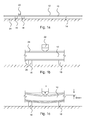
- an elongate aircraft wing stringer 10 is shown having an upper surface 12 and a lower surface 14.
- the example stringer is an I-beam having a top flange 24 and a bottom flange 26.
- the stringer 10 is supported at its lower surface 14 on two space supports 16, 18 supported on ground 20.
- a punch 22 can be moved in a vertical direction in order to deform the stringer 10 between the two supports 16, 18.
- Such punching apparatuses are known and will not be described in detail here.
- d punch is defined as the amount by which the punch 22 is advanced from a starting position in contact with the top surface 12 of the stringer 10 to the position of Figure 1c .
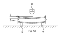
- the punch 22 has been retracted and the stringer 10 will spring back by an elastic punch limit, d elastic , leaving a final punched deformation of d plastic .
- the method of obtaining the required d plastic is to progressively deform the beam, repeating the steps of Figures 1c and 1d , recording both d punch and d plastic until the desired deformation is met. Subsequent forming operations at that point along the beam are then used to refine this method until a suitable d punch is found for the required d plastic .
- d punch ⁇ I xx ⁇ BB 1 ⁇ b ⁇ Y 2 + BB 2 ⁇ b ⁇ Y + BB 3 ⁇ b 2 + 4 ⁇ I xx ⁇ d plastic ⁇ BB 1 ⁇ a ⁇ Y 2 + BB 2 ⁇ a ⁇ Y + BB 3 ⁇ a - BB 1 ⁇ b ⁇ Y 2 + BB 2 ⁇ b ⁇ Y + BB 3 ⁇ b ⁇ I xx 2 ⁇ I xx ⁇ BB 1 ⁇ a ⁇ Y 2 + BB 2 ⁇ a ⁇ Y + BB 3 ⁇ a - d elastic
- the present invention provides a method of manufacturing using a prediction of the punch force required by the process.
Landscapes
- Engineering & Computer Science (AREA)
- Human Computer Interaction (AREA)
- Manufacturing & Machinery (AREA)
- Physics & Mathematics (AREA)
- General Physics & Mathematics (AREA)
- Automation & Control Theory (AREA)
- Investigating Strength Of Materials By Application Of Mechanical Stress (AREA)
- Vehicle Body Suspensions (AREA)
- Bending Of Plates, Rods, And Pipes (AREA)
Abstract
Description
- The present invention is concerned with a method of manufacturing elongate components. More particularly, the present invention is concerned with a method of manufacturing elongate aircraft components such as aircraft wing stringers by inducing plastic deformation by a differential contact three point bending operation.
- Components such as aircraft stringers need to be shaped to the wing aerodynamic profile. In order to achieve this, stringers are plastically deformed by differential contact three point bending. By "differential contact three point bending" we mean a process by which the stringer is supported at two spaced positions on a first side. A punch is applied therebetween from a second, opposite side in order to induce a bending moment to cause local plastic deformation. Because the stringer deforms as the punch progresses, the contact area with the punch and the supports may change. This is not a classical three point bending load case (the forces are not point loads) and as such is defined as "differential contact".
- One problem with this method is that the stringer will spring back after the bending moment is released due to its elasticity. Known methods of forming are non-predictive. The operator will attempt to estimate the amount of punch movement required to provide a given plastic deformation. The punch is applied to the stringer by the estimated value and the plastic deformation is measured once the punch is retracted. If the level of deformation is too low, the operator will estimate a further punch distance and reapply the punch. Successive bending operations are applied at the same position until the required deformation is achieved. The punch information is then stored and applied to the next component, and so on until the required "first time" punch movement is refined to a satisfactory degree.
- A typical 18m stringer will be have up to 250 punching locations along its length. As such it is desirable to reduce the number of punching operations at each station. Should the stringer be overdeformed (i.e. undergo too much deformation when punched), scrapping the part is not feasible as such parts are very expensive. As such, an inverse bending moment (again, estimated by the operator) is applied to the component to reverse the deformation. Such repeated and reverse application of plastic deformation to the stringer can cause problems such as work hardening and fatigue.
- Because of the complex and changing geometry of the stringers used in the aerospace sector, prediction of the stringer plastic deformation by analytical methods is not appropriate.
- An alternative is to use numerical simulation, such as finite element analysis (FEA) to predict the deformation of the stringer at each punch location. Not only would the analysis of a single stringer need to be repeated at each punch stage (in order to arrive at the required plastic deformation), but because of the changing cross section of the stringer along its length, these analyses would need to be carried out for each discrete punch position. This would be extremely time consuming and costly with respect to computing resource.
- It is an aim of the present invention to provide an improved method of manufacture which mitigates the "trial and error" method of the prior art, whilst utilising the benefits of numerical simulation without undue burden.
- According to the invention there is provided a method of manufacturing an elongate component comprising the steps of:
- providing a punching apparatus configured to apply a differential contact three point bending load to the component by advancing a punch at a punch location between two supports by a punch distance,
- calculating a punch travel (dpunch) based on the second moment of inertia of the component at the punch location (Ixx), the location of the neutral axis distance of the component at the punch location (Y) and the required plastic deformation (dplastic) of the component at the punch location,
- bending the elongate component at the punch location by moving the punch by the punch travel.
- Preferably the punch travel is calculated assuming that the required plastic deformation (dplastic) is related to the second moment of inertia of the component at the punch location (Ixx), and the neutral axis distance at the punch location (Y) by an nth order polynomial of the form:

where Bi are functions of the punch travel (dpunch). - Preferably:

where BBij are constants. - Preferably which n=m=2; i.e. the polynomials are quadratic.
- Preferably the punch travel is calculated from the expression:

where BB1a, BB1b etc are constants. - Preferably delastic is calculated analytically from the cross section of the stringer at the punch location.
- Constants BB1a, BB1b etc are preferably calculated statistically from a representative sample of numerical simulations, which may be finite element analyses.
- A method in accordance with the present invention will now be described with reference to the accompanying figures in which:-
-
FIGURE 1a is a view of a stringer undergoing a punching operation; -
FIGURE 1b is a close-up view of the stringer ofFigure 1a , pre-punching; -
FIGURE 1c is a close-up view similar to that ofFigure 1b during the punching operation; and -
FIGURE 1d is a close-up view similar toFigures 1b and 1c post punching. - Turning to
Figure 1a , an elongateaircraft wing stringer 10 is shown having anupper surface 12 and alower surface 14. As shown infigure 1b , the example stringer is an I-beam having atop flange 24 and abottom flange 26. - The
stringer 10 is supported at itslower surface 14 on two space supports 16, 18 supported onground 20. Apunch 22 can be moved in a vertical direction in order to deform thestringer 10 between the two supports 16, 18. Such punching apparatuses are known and will not be described in detail here. - In order to deform the stringer to the profile of a desired aircraft wing, the
punch 22 is pushed downwards with a force F by a punch deflection dpunch. dpunch is defined as the amount by which thepunch 22 is advanced from a starting position in contact with thetop surface 12 of thestringer 10 to the position ofFigure 1c . - As shown in
Figure 1c , as thepunch 22 is advanced, thestringer 10 deforms both elastically and, eventually, plastically. The total deformation of the stringer at the point of contact with the punch is dpunch. - Turning to
Figure 1d , thepunch 22 has been retracted and thestringer 10 will spring back by an elastic punch limit, delastic, leaving a final punched deformation of dplastic. As mentioned above, the method of obtaining the required dplastic is to progressively deform the beam, repeating the steps ofFigures 1c and1d , recording both dpunch and dplastic until the desired deformation is met. Subsequent forming operations at that point along the beam are then used to refine this method until a suitable dpunch is found for the required dplastic. - Stringer cross sections vary along their length in both size and shape. The prior art iterative process must therefore be carried out for each individual punch location, of which there are many.
- Assuming that the second moment of inertia and the neutral axis of the stringer between the
supports 
where: - Ixx = Second moment of inertia of the beam cross section,
- Y = Neutral axis of beam cross section,
- B1 = Quadratic function of punch movement, dpunch (see below)
- B2 = Quadratic function of punch movement, dpunch (see below)
- B3 = Quadratic function of punch movement, dpunch (see below)


where:- BB1a, BB1b etc are material dependent constants to be determined.
- This series of equations is indeterminate. Therefore a numerical solution is used. Values for the various constants (BB1a, BB1b etc) are derived from a number of selective numerical finite element analysis simulations. An example of a range of representative I-stringer geometries is shown in
Figures 2a and 2b . - Once a representative number of FEA simulations have been run, say 8 different values of dpunch from 4 to 11mm for each of the cross sections listed in
Figure 2b , the results can be summarised as shown inFigure 3a and plotted as shown inFigure 3b , with values of dplastic / Ixx vs Y. These plots, for each constant value of dpunch are thereby representative of equation (1) above. - From this analysis, a series of curves are retained such that the constants BB1a, BB1b etc can be plotted against (dpunch - delastic). (NB the elastic punch limit delastic is determined analytically). The least squares method used to calculate the values of BB1a, BB1B etc.
- This allows the relationship between dpunch and each of B1, B2, B3 to be plotted (see
Figures 4a to 4c ) and hence values of BB1a, BB1b etc to be determined by least squares regression. - Once all of the constants have been determined, the value of dpunch as a function of required plastic deformation dplastic can be predicted using the following relation:

- In addition, the present invention provides a method of manufacturing using a prediction of the punch force required by the process.
- Variations of the above embodiment fall within the scope of the present invention.
Claims (9)
- A method of manufacturing an elongate component comprising the steps of:providing a punching apparatus configured to apply a differential contact three point bending load to the component by advancing a punch at a punch location between two supports by a punch distance,calculating a punch travel (dpunch) based on the second moment of inertia of the component at the punch location (Ixx), the location of the neutral axis of the component at the punch location (Y) and the required plastic deformation (dplastic) of the component at the punch location,bending the elongate component at the punch location by moving the punch by the punch travel (dpunch).
- A method of manufacturing an elongate component according to claim 1 in which the punch travel is calculated assuming that the required plastic deformation (dplastic) is related to the second moment of inertia of the component at the punch location (Ixx), and the neutral axis distance at the punch location (Y) by an nth order polynomial of the form:

where Bi are functions of the punch travel (dpunch). - A method of manufacturing an elongate component according to claim 2 in which:
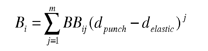
where BBij are constants. - A method of manufacturing an elongate component according to claim 2 or 3 in which n=2.
- A method of manufacturing an elongate component according to any of claims 2 to 4 in which m=2.
- A method of manufacturing an elongate component according to any preceding claim in which the punch travel is calculated from the expression:

where BB1a, BB1b etc are constants. - A method of manufacturing an elongate component according to any of claims 3 to 6 in which delastic is calculated analytically.
- A method of manufacturing an elongate component according to any of claims 3 to 7 in which constants BB1a, BB1b etc are calculated statistically from a representative sample of numerical simulations.
- A method of manufacturing an elongate component according to claim 8 in which the numerical simulations are finite element analyses.
Applications Claiming Priority (1)
| Application Number | Priority Date | Filing Date | Title |
|---|---|---|---|
| GBGB1114438.3A GB201114438D0 (en) | 2011-08-22 | 2011-08-22 | A method of manufacturing an elongate component |
Publications (2)
| Publication Number | Publication Date |
|---|---|
| EP2562613A2 true EP2562613A2 (en) | 2013-02-27 |
| EP2562613A3 EP2562613A3 (en) | 2016-03-30 |
Family
ID=44800659
Family Applications (1)
| Application Number | Title | Priority Date | Filing Date |
|---|---|---|---|
| EP12179138.8A Withdrawn EP2562613A3 (en) | 2011-08-22 | 2012-08-03 | A method of manufacturing an elongate component |
Country Status (4)
| Country | Link |
|---|---|
| US (1) | US9201417B2 (en) |
| EP (1) | EP2562613A3 (en) |
| CN (1) | CN102950178B (en) |
| GB (1) | GB201114438D0 (en) |
Family Cites Families (39)
| Publication number | Priority date | Publication date | Assignee | Title |
|---|---|---|---|---|
| JPS5373004U (en) * | 1976-11-22 | 1978-06-19 | ||
| JPS6141740A (en) * | 1984-08-02 | 1986-02-28 | Natl Res Inst For Metals | Intermetallic tial compound-base heat resistant alloy |
| LU86442A1 (en) * | 1986-05-23 | 1987-12-16 | Arbed | PROCESS FOR THE MANUFACTURE OF PRE-STRESSED STEEL BEAMS |
| US4802357A (en) * | 1987-05-28 | 1989-02-07 | The Boeing Company | Apparatus and method of compensating for springback in a workpiece |
| US4864509A (en) * | 1987-09-29 | 1989-09-05 | The Boeing Company | Method and related apparatus for controlling the operation of a press brake |
| SU1574315A1 (en) | 1988-05-16 | 1990-06-30 | Предприятие П/Я А-1944 | Die for bending shaped blanks |
| JPH0279455A (en) * | 1988-09-14 | 1990-03-20 | Mitsubishi Electric Corp | Bending method for lead of electric parts |
| US5128877A (en) * | 1990-06-08 | 1992-07-07 | Ford Motor Company | Method of draw forming analytically determined binder wrap blank shape |
| EP0753362B1 (en) * | 1994-03-29 | 2001-05-16 | Komatsu Ltd. | Press brake |
| JPH08192230A (en) | 1995-01-18 | 1996-07-30 | Sango Co Ltd | Device for bending pipe |
| US6192732B1 (en) * | 1996-10-03 | 2001-02-27 | Komatsu Ltd. | Bending method and bending apparatus for bending machine |
| USRE38340E1 (en) * | 1996-11-04 | 2003-12-02 | Seagate Technology Llc | Multi-point bending of bars during fabrication of magnetic recording heads |
| JP3266099B2 (en) * | 1998-03-27 | 2002-03-18 | 株式会社神戸製鋼所 | Aluminum alloy door beam |
| FR2796320B1 (en) * | 1999-07-13 | 2001-10-05 | Amada Europ Sa | IMPROVED PRECISION FOLDING PRESS |
| EP1083403A1 (en) * | 1999-09-08 | 2001-03-14 | Bystronic Laser AG | Procedure and device to determine the bending angle of objects |
| KR100519521B1 (en) * | 1999-10-07 | 2005-10-05 | 무라타 기카이 가부시키가이샤 | A press machine and its driving method |
| JP2001170710A (en) * | 1999-12-13 | 2001-06-26 | Amada Co Ltd | Upper die for deep bending |
| JP4558877B2 (en) * | 2000-01-17 | 2010-10-06 | 株式会社アマダ | Bending method and apparatus |
| TW536432B (en) * | 2000-01-17 | 2003-06-11 | Amada Co Ltd | Method and system for processing a sheet member, and various devices relating to such system |
| ES2241566T3 (en) * | 2000-01-24 | 2005-11-01 | Bystronic Laser Ag | PROCEDURE FOR REGULATION OF THE RACE OF A FOLDING PRESS. |
| US6959573B2 (en) * | 2000-08-11 | 2005-11-01 | Amada Company, Limited | Bending method and device therefore |
| JP4700801B2 (en) * | 2000-12-07 | 2011-06-15 | 株式会社アマダ | Bending method |
| US20030121303A1 (en) * | 2001-12-28 | 2003-07-03 | Lanni Arthur L. | Die set with position sensor mounted thereon |
| EP1452302B1 (en) * | 2003-02-26 | 2009-04-08 | Bystronic Laser AG | Process for correcting a bending operation and press brake |
| ITPR20040010A1 (en) * | 2004-02-18 | 2004-05-18 | Set 2002 S R L | PROCEDURE AND PNEUMATIC DEVICE FOR DETECTING THE BENDING ANGLE OF A SHEET OF SHEET IN A FOLDING PRESS. |
| JP4668709B2 (en) * | 2004-08-06 | 2011-04-13 | 株式会社アマダ | Processed material, surface protection sheet and processing method |
| KR100591261B1 (en) | 2004-08-31 | 2006-06-19 | (주) 동희산업 | Torsion beam forming method and torsion beam forming apparatus of torsion beam suspension system |
| JP2006071972A (en) * | 2004-09-02 | 2006-03-16 | Sharp Corp | Display device |
| WO2006054596A1 (en) * | 2004-11-17 | 2006-05-26 | Amada Company, Limited | Bending method, and die and bending machine used for the bending method |
| JP2006205256A (en) * | 2004-12-27 | 2006-08-10 | Amada Co Ltd | Work bending angle detecting device and work bending machine |
| CN101616758B (en) * | 2007-02-21 | 2012-07-11 | 新日本制铁株式会社 | Apparatus and method for press-bending tube material |
| KR100958977B1 (en) * | 2007-07-25 | 2010-05-20 | 주식회사 포스코 | Tubular torsion beam for rear wheel suspension of automobile and manufacturing method thereof |
| GB2450765B (en) * | 2007-11-13 | 2009-05-20 | Hadley Ind Holdings Ltd | Sheet material |
| ITMI20072372A1 (en) * | 2007-12-19 | 2009-06-20 | Ibf S P A | PROCEDURE FOR BENDING TUBULAR ARTICLES WITH A REPORT> 3 BETWEEN THE BENDING RADIUS AND THE EXWERN DIAMETER OF THE FINISHED TUBE |
| JP5203234B2 (en) | 2009-01-20 | 2013-06-05 | 第一電子工業株式会社 | Electrical connector |
| JP5187219B2 (en) * | 2009-02-12 | 2013-04-24 | 富士通株式会社 | Measuring device, measuring method and measuring program |
| JP5851813B2 (en) * | 2011-12-05 | 2016-02-03 | 三菱重工業株式会社 | Curvature holding device, curving method and curving method for plate-like workpiece |
| US8863585B2 (en) * | 2012-02-14 | 2014-10-21 | Ut-Battelle, Llc | Reversal bending fatigue testing |
| US10086484B2 (en) * | 2012-10-12 | 2018-10-02 | Apple Inc. | Manufacturing of computing devices |
-
2011
- 2011-08-22 GB GBGB1114438.3A patent/GB201114438D0/en not_active Ceased
-
2012
- 2012-08-03 EP EP12179138.8A patent/EP2562613A3/en not_active Withdrawn
- 2012-08-06 US US13/567,435 patent/US9201417B2/en not_active Expired - Fee Related
- 2012-08-22 CN CN201210300091.1A patent/CN102950178B/en not_active Expired - Fee Related
Non-Patent Citations (1)
| Title |
|---|
| None |
Also Published As
| Publication number | Publication date |
|---|---|
| US20130047416A1 (en) | 2013-02-28 |
| EP2562613A3 (en) | 2016-03-30 |
| CN102950178B (en) | 2016-05-11 |
| US9201417B2 (en) | 2015-12-01 |
| CN102950178A (en) | 2013-03-06 |
| GB201114438D0 (en) | 2011-10-05 |
Similar Documents
| Publication | Publication Date | Title |
|---|---|---|
| Hambli et al. | Fracture criteria identification using an inverse technique method and blanking experiment | |
| Hambli | Blanking tool wear modeling using the finite element method | |
| Tang et al. | Size-dependent nonlinear post-buckling analysis of functionally graded porous Timoshenko microbeam with nonlocal integral models | |
| CN104715085B (en) | The method and blanking equipment of the actual physics parameter of reverse plate | |
| Zhou et al. | Elastic-plastic buckling analysis of stiffened panel subjected to global bending in forming process | |
| Cha et al. | Quantification of micro-cracks on the bending surface of roll formed products using the GTN model | |
| US9201417B2 (en) | Method of manufacturing an elongate component | |
| Le Maoût et al. | Drawing, flanging and hemming of metallic thin sheets: a multi-step process | |
| Achouri et al. | Influence of the edge rounding process on the behaviour of blanked parts: numerical predictions with experimental correlation | |
| Wasif et al. | Prediction of Springback using the Machine Learning Technique in high-tensile strength sheet metal during the V-Bending Process. | |
| Yoshida et al. | Evaluation and improving methods of stretch flangeability | |
| Chung et al. | Numerical improvement of viscoplastic, non-linear, finite-element analysis | |
| Carvalho-Resende et al. | Numerical investigation and experimental validation of a plasticity model for sheet steel forming | |
| Hadoush et al. | A numerical investigation of the continuous bending under tension test | |
| Younis et al. | Experimental evaluation and finite element simulation to produce square cup by deep drawing process | |
| Parsa et al. | Improvement of initial blank shape for intricate products using slip line field | |
| EP4009216A1 (en) | Method for modelling a collision of two vehicles | |
| Wang et al. | An efficient force prediction strategy for single point incremental sheet forming | |
| Huang et al. | An elasto-plastic finite-element analysis of sheet metal camber process | |
| Da Silva Botelho et al. | Experimental and finite element analysis of spring back in sheet metal forming | |
| Köhler et al. | Forming of stringer sheets with solid tools | |
| Tkocz et al. | Application of incremental metal forming for production of aircraft integral panels | |
| Gawade et al. | Investigation of springback in U shape bending with holes in component | |
| Wen et al. | Research on cutting end flaring of C-shaped steel roll forming process | |
| ul Hassan et al. | Finite element simulations for sheet metal forming process with functional input for the minimization of springback |
Legal Events
| Date | Code | Title | Description |
|---|---|---|---|
| PUAI | Public reference made under article 153(3) epc to a published international application that has entered the european phase |
Free format text: ORIGINAL CODE: 0009012 |
|
| AK | Designated contracting states |
Kind code of ref document: A2 Designated state(s): AL AT BE BG CH CY CZ DE DK EE ES FI FR GB GR HR HU IE IS IT LI LT LU LV MC MK MT NL NO PL PT RO RS SE SI SK SM TR |
|
| AX | Request for extension of the european patent |
Extension state: BA ME |
|
| PUAL | Search report despatched |
Free format text: ORIGINAL CODE: 0009013 |
|
| AK | Designated contracting states |
Kind code of ref document: A3 Designated state(s): AL AT BE BG CH CY CZ DE DK EE ES FI FR GB GR HR HU IE IS IT LI LT LU LV MC MK MT NL NO PL PT RO RS SE SI SK SM TR |
|
| AX | Request for extension of the european patent |
Extension state: BA ME |
|
| RIC1 | Information provided on ipc code assigned before grant |
Ipc: B21D 5/02 20060101ALI20160222BHEP Ipc: B21D 5/00 20060101ALI20160222BHEP Ipc: G05B 19/18 20060101AFI20160222BHEP Ipc: B21D 7/12 20060101ALI20160222BHEP |
|
| 17P | Request for examination filed |
Effective date: 20160607 |
|
| RBV | Designated contracting states (corrected) |
Designated state(s): AL AT BE BG CH CY CZ DE DK EE ES FI FR GB GR HR HU IE IS IT LI LT LU LV MC MK MT NL NO PL PT RO RS SE SI SK SM TR |
|
| GRAP | Despatch of communication of intention to grant a patent |
Free format text: ORIGINAL CODE: EPIDOSNIGR1 |
|
| INTG | Intention to grant announced |
Effective date: 20161201 |
|
| STAA | Information on the status of an ep patent application or granted ep patent |
Free format text: STATUS: THE APPLICATION IS DEEMED TO BE WITHDRAWN |
|
| 18D | Application deemed to be withdrawn |
Effective date: 20170412 |