EP2562532A1 - Optical detecting method and device for long-term continuously monitoring liquid concentration - Google Patents
Optical detecting method and device for long-term continuously monitoring liquid concentration Download PDFInfo
- Publication number
- EP2562532A1 EP2562532A1 EP10850067A EP10850067A EP2562532A1 EP 2562532 A1 EP2562532 A1 EP 2562532A1 EP 10850067 A EP10850067 A EP 10850067A EP 10850067 A EP10850067 A EP 10850067A EP 2562532 A1 EP2562532 A1 EP 2562532A1
- Authority
- EP
- European Patent Office
- Prior art keywords
- plunger
- testing solution
- solution
- light
- chamber
- Prior art date
- Legal status (The legal status is an assumption and is not a legal conclusion. Google has not performed a legal analysis and makes no representation as to the accuracy of the status listed.)
- Granted
Links
Images

Classifications
-
- G—PHYSICS
- G01—MEASURING; TESTING
- G01N—INVESTIGATING OR ANALYSING MATERIALS BY DETERMINING THEIR CHEMICAL OR PHYSICAL PROPERTIES
- G01N21/00—Investigating or analysing materials by the use of optical means, i.e. using sub-millimetre waves, infrared, visible or ultraviolet light
- G01N21/01—Arrangements or apparatus for facilitating the optical investigation
- G01N21/03—Cuvette constructions
-
- G—PHYSICS
- G01—MEASURING; TESTING
- G01N—INVESTIGATING OR ANALYSING MATERIALS BY DETERMINING THEIR CHEMICAL OR PHYSICAL PROPERTIES
- G01N21/00—Investigating or analysing materials by the use of optical means, i.e. using sub-millimetre waves, infrared, visible or ultraviolet light
- G01N21/17—Systems in which incident light is modified in accordance with the properties of the material investigated
- G01N21/25—Colour; Spectral properties, i.e. comparison of effect of material on the light at two or more different wavelengths or wavelength bands
- G01N21/31—Investigating relative effect of material at wavelengths characteristic of specific elements or molecules, e.g. atomic absorption spectrometry
Definitions
- the present invention involves an optical measurement method and apparatus, and specifically relates to an optical measurement method and apparatus for long-term and continuous monitoring of liquid concentration.
- Measurement technology is a direct way to obtain data, which is essential for the automation and informatization of process.
- the present invention provides an optical measurement method and apparatus for long-term and continuous monitoring of the liquid concentration.
- the solution provided by the present invention for technical problems thereof is an optical measurement method for long-term and continuous monitoring of the liquid concentration, which mainly comprises the following steps:
- C1 refers to current concentration of testing solution and C2 refers to known concentration of the reference solution.
- step (b) repeating the steps (3) ⁇ (4) to obtain current change in absorbance of the testing solution, and then using the relation curve of change in absorbance with concentration of the testing solution obtained by step (a) to get current concentration of the testing solution.
- the chamber for the testing solution connects with external testing solution through a sample inlet/outlet
- the chamber for the reference solution also connects with external reference solution through its sample inlet/outlet.
- the apparatus of the present invention for conducting long-term and continuous optical monitoring of liquid concentration includes a fixed support; a movable sleeve; first and second hollow plungers. wherein the movable sleeve is sealed with a piece of light transmissive glass fixed inside; the first and second hollow plungers, which are also placed in the movable sleeve, are on two sides of the light transmission glass respectively and form a dynamic seal with the movable sleeve; the first and second plunger, outer ends of which are connected and fixed with the fixed support, are both sealed with a piece of plunger glass fixed inside, wherein central axes of the two pieces of glass coincide with each other; length of the movable sleeve is more than twice of distance between the plunger glass of the first and second plungers; a chamber for reference solution is formed between inner end face of the plunger glass of the first plunger and the light transmission glass, and a chamber for testing solution is formed between inner end face of the plunger glass of the second plunger and
- the two pieces of plunger glass of the present invention are at the head of the inner end of the first and second plungers respectively.
- a parallel ray generator is set in cavity of said first plunger and a light receiver is set in the cavity of said second plunger; the parallel light generator is opposite outer end face of the plunger glass inside the first plunger and the light receiver is opposite outer end face of the plunger glass inside the second plunger.
- a light receiver is set in the cavity of said first plunger and parallel ray generator is set in the cavity of said second plunger; the light receiver is opposite outer end face of the plunger glass inside the first plunger and the parallel light generator is opposite outer end face of the plunger glass inside the second plunger.
- a stepping motor included whose output shaft is connected with a motor screw rod; the said movable sleeve is connected with fixed fastenings that move together with the said motor screw rod by screw thread.
- the present invention by innovating optical measurement theory and providing corresponding technical solution, solves stability problems during long-term operation of optical measurement devices, i.e., overcoming environmental disturbance during the measurement process.
- the invention might eliminate disturbance factors, i.e., a disturbance quantity A (factors including aging effect of light source, base drift of sensor), a disturbance quantity B (factors including erosion, abrasion and living things adherence problem of glass), etc., as constant variables, and prevents measurement results from disturbance.
- a disturbance quantity A factors including aging effect of light source, base drift of sensor
- a disturbance quantity B factors including erosion, abrasion and living things adherence problem of glass
- a formula C 1 ln ⁇ I 1 ⁇ ⁇ ⁇ 2 ⁇ - ln ⁇ I 2 ⁇ ⁇ ⁇ 2 ⁇ - ln ⁇ I 1 ⁇ ⁇ ⁇ 2 ⁇ + ln ⁇ I 2 ⁇ ⁇ ⁇ 2 ⁇ ln ⁇ I 2 ⁇ ⁇ ⁇ 1 ⁇ - ln ⁇ I 1 ⁇ ⁇ ⁇ 1 ⁇ + ln ⁇ I 1 ⁇ ⁇ ⁇ 1 ⁇ - ln ⁇ I 2 ⁇ ⁇ ⁇ 1 ⁇ C 2 can be used to obtain concentration of testing solution.
- the concentration of the testing solution is only relevant with the concentration of the reference solution, with no relation with other disturbance factors.
- the concentration of the testing solution would be accurate provided that the concentration of the reference solution is accurate. In such a way, a real-time and online calibration of the concentration of the testing solution might be achieved and a long-term and continuous monitoring of the concentration of the testing solution might be implemented.
- the invention is applicable to accurate measurement in chemical production process, continuous monitoring of pollution of "three wastes (waste gas, waste water and industrial residue)", as well as tracing and measurement of ecological factor in marine environment.
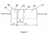
- Figure 1 is a working principle diagram of a optical measurement method of the invention.
- Figure 2 is a structure diagram of a measurement apparatus for optical measurement method of the invention.
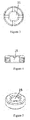
- Figure 3 is a structure diagram of nut in an optical measurement apparatus of the invention.
- Figure 4 is a sectional view of A-A in the figure 3 .
- Figure 5 is a stereoscopic structure diagram of nut of the invention.
- IC denotes intensity of emerging light
- I0 denotes intensity of emitting light
- ⁇ denotes light absorption constant of light absorbing substance
- c denotes concentration of the light absorbing substance
- L denotes optical path length of measurement light.
- the fixed chamber with fixed optical path 15 is divided into a chamber for testing solution 18 and a chamber for reference solution 19 by a light transmissive device 20.
- the chamber for testing solution 18 is connected with the outside through an inlet/outlet of chamber for testing solution 16, and the chamber for reference solution 19 is connected with the outside through an inlet/outlet of chamber for reference solution 17.
- solutions need to be injected into the chamber for testing solution 18 and the chamber for reference solution 19 external solution can be injected through its own inlet/outlet.
- the solutions in the chamber for testing solution 18 and the chamber for reference solution 19 the solutions can be discharged through their own inlet/outlet.
- the chamber for testing solution 18 is connected with the outside through the inlet/outlet of chamber for testing solution 16 when the light transmissive device is moved to change optical path length of the testing solution and the reference solution, pressure of testing solution and reference solution can be kept unchanged.
- I c I 0 . e - ⁇ 1 ⁇ C 1 ⁇ L 1 . e - ⁇ 2 ⁇ C 2 ⁇ L 2
- ⁇ 1 , C 1 and L 1 refer to the absorption coefficient, concentration and optical path length of the testing solution, respectively; and ⁇ 2 , C 2 and L 2 refer to the absorption coefficient, concentration and optical path length of the reference solution, respectively.
- I 1 I 0 . e - ⁇ 1 ⁇ C 1 ⁇ L 1 . e - ⁇ 2 ⁇ C 2 ⁇ L 2 . e - ⁇ A ⁇ c A ⁇ L A . e - ⁇ B ⁇ c B ⁇ L B
- ⁇ A , C A and L A refer to the absorption coefficient, concentration or density and optical path length of disturbance quantity A, respectively;
- ⁇ B , C B and L B refer to the absorption coefficient, concentration or density and optical path length of disturbance quantity B, respectively;
- I1 refers to the absorbed light intensity.
- the light transmissive device 20 While keeping the light transmit through the testing solution, light transmissive device 20 and reference solution, the light transmissive device 20 is moved to change light path length of the testing solution and the reference solution and the pressure of the two solutions is kept unchanged. That is, when the chamber for testing solution or the chamber for reference solution becomes larger, it would result in a lower pressure or light not transmitting though the solution totally, and there is a need to inject solution again and the solution can be injected through its inlet / outlet. Similarly, when the chamber for testing solution or the chamber for the reference solution becomes smaller, it would result in a higher pressure, and there is need to discharge solution again and the solution can be discharged through its inlet/outlet.
- the disturbance quantity A and the disturbance quantity B are results of a long and slow process, they can be treated as constant variables during two contiguous measurement periods. If optical path length of the testing solution is increased by ⁇ L , then the optical path of the reference solution is reduced by ⁇ L and measurement equation of the later measurement period can be expressed as the formula (4):
- I 2 I 0 . e - ⁇ 1 ⁇ C 1 ⁇ L 1 + ⁇ ⁇ L . e - ⁇ 2 ⁇ C 2 ⁇ L 2 - ⁇ ⁇ L . e - ⁇ A ⁇ c A ⁇ L A . e - ⁇ B ⁇ c B ⁇ L B
- I 2 ⁇ 2 . C 2 - ⁇ 1 . C 1 . ⁇ ⁇ L
- I 1 ⁇ and I 2 ⁇ refer to the intensities of emerging light with wavelength of ⁇ ' before and after changing the optical path length
- ⁇ 2 ⁇ refers to absorption coefficient of reference solution to the emerging light with wavelength of ⁇ '
- C 2 refers to concentration of the reference solution
- ⁇ 1 ⁇ refers to absorption coefficient of testing solution to the emerging light with wavelength of ⁇ '
- C 1 refers to the concentration of testing solution
- I 1 ⁇ and I 2 ⁇ refer to the intensities of emerging light with wavelength of ⁇ " before and after changing the optical path length
- ⁇ 2 ⁇ refers to absorption coefficient of reference solution to the emerging light with wavelength of ⁇ "
- ⁇ 1 ⁇ refers to absorption coefficient of testing solution to the emerging light with wavelength of ⁇ "
- I 1 ⁇ , I 2 ⁇ , I 1 ⁇ and I 2 ⁇ can be obtained by measurement, and constants including ⁇ 2 ⁇ , ⁇ 1 ⁇ , ⁇ 2 ⁇ and ⁇ 1 ⁇ can
- the current concentration C 1 is relevant only with the parameters: I 1 ⁇ , I 2 ⁇ , I 1 ⁇ , I 2 ⁇ , ⁇ 2 ⁇ , ⁇ 1 ⁇ , ⁇ 2 ⁇ , ⁇ 1 ⁇ and C 2 , but is not relevant with disturbance quantities of stability: ⁇ A , C A , L A , ⁇ B , C B and L B and the intensity of emitting light I0. Therefore, the optical measurement method for monitoring liquid concentration of the present invention can successfully eliminates the influence of the disturbance quantity of stability on measurement and conduct long-term and continuous monitoring of liquid concentration.
- the current concentration of the testing solution can be calculated according to formula (7) provided I 1 ⁇ , I 2 ⁇ , I 1 ⁇ , I 2 ⁇ , ⁇ 2 ⁇ , ⁇ 1 ⁇ , ⁇ 2 ⁇ , ⁇ 1 ⁇ and C 2 can be obtained.
- the optical measurement method of the present invention for long-term and continuous monitoring of the concentration of liquid mainly comprises the following steps:
- C1 refers to current concentration of the testing solution and C2 refers to known concentration of the reference solution.
- the spectrophotometric measurement method calculates the current concentration of testing solution using the relation curve of absorbancy and concentration. Therefore, the present invention can change the concentration of the testing solution and repeat the described steps (3) - (5) to establish the relation curve of the change in absorbance of the testing solution and the concentration; and repeat the described steps (3) - (4) to obtain current change in absorbance of the testing solution, and then to obtain the current concentration of the testing solution using the aforesaid relation curve.
- Figure 2 shows structure of a measurement apparatus for the optical measurement method of the invention, which conducts long-term and continuous optical monitoring of liquid concentration.
- a movable sleeve 1 is a tube-shaped structure with part of a first plunger 2 and a second plunger 2' therein.
- the inner diameter of the movable sleeve 1 matches with outer diameter of the first plunger 2 and the second plunger 2', so as to enable the first plunger 2 and second plunger 2' to form a dynamic seal with the movable sleeve 1 by a ⁇ -shaped seal rings and a fixed chamber in the movable sleeve 1 which locates between the first plunger 2 and the second plunger 2'.
- the movable sleeve 1 is sealed with a piece of fixed light transmission glass 7 inside, and the first plunger 2 and the second plunger 2' are on the side of light transmission glass respectively, making the fixed chamber surrounded by the movable sleeve 1 and the first plunger 2 and the second plunger 2' divided into two independent chambers, i.e., a chamber for testing solution 5 and a chamber for reference solution 9.
- the light transmission glass 7 can be a plain glass made of organic glass, ordinary industrial glass or toughened glass.
- the first plunger 2 and the second plunger 2' are two fixed plunders with the same hollow and tube-shaped structure.
- the chambers in one end of the first plunger 2 and the second plunger 2' are sealed with a piece of fixed plunger glass 4.
- the inner end face of plunger glass 4 of the first plunger 2 forms the chamber for reference solution 5 with the light transmission glass 7; and the inner end face of plunger glass of the second plunger 2' forms the chamber for testing solution 9 with the light transmission glass 7; there are inlet/outlet of testing solution 6 and inlet/outlet of reference solution 8 on the wall of movable sleeve.
- the inlet/outlet of testing solution 6 connects with the chamber for testing solution 5 and the inlet/outlet of reference solution 8 connects with the chamber for reference solution 9.
- the central axis of the two pieces of plunger glass of the first plunger 2 and the second plunger 2' coincide with each other to ensure light entered from one plunger glass being parallel through the other plunger glass totally.
- the plunger glass 4 can be flat glass made of highly transparent materials, such as organic glass, ordinary industrial glass or toughened glass, to ensure the parallel light in the measurement being able to go through the plunger glass 4.
- the plunger glass 4 can be fixed on the inner wall of the first plunger 2 and the second plunger 2' with the nut 14.
- the nut 14, made with outer screw thread, can be connected with the inner screw thread of the first plunger 2 and the second plunger 2' to enable the plunger glass 4 being installed and operated easily.
- the plunger glass 4 can be fixed on the head of the inner end of the first plunger 2 and the second plunger 2' (the end near the light transmission glass 7), making the minimum light path length of the testing solution and the reference solution be close to 0.
- the measurement apparatus of the invention can be more flexible to have a larger measurable range of the concentration of the testing solution.
- the plunger glass of the measurement apparatus is not fixed on the head of the inner end of the first plunger 2 and the second plunger 2' near the light transmission glass 7, but on the other positions inside the first plunger 2 and second plunger 2' instead, the continuous monitoring of the concentration of the testing solution can also be implemented. It should be pointed out that there is a central though-hole 15 in the nut 14 to ensure enough light transmission of the plunger glass and a unblocked light path between the two pieces of plunger glass 4.
- the outer ends of the first plunger 2 and the second plunger 2' (the end far from the light transmission glass 7) are fixed with the fixed support 12, respectively, forming the optical path length between the plunger glass 4 of the first plunger 2 and the plunger glass 4 of the second plunger 2'.
- the movable sleeve 1, the first plunger 2, the second plunger 2' and the light transmission glass 7 make up two structures, whose optical path length is changed synchronously and reversely with the same amplitude.
- the length of the movable sleeve 1 is more than twice of the distance between the plunger glass of the first and second plunger, to ensure part of inner end of the first and second plunger being in the movable sleeve 1 when the movable sleeve 1 is moved, in order to avoid the first and second plunger from breaking away from the movable sleeve 1.
- the measurement apparatus for solution concentration used in the present invention there can be a parallel light generator 3 in the cavity of said first plunger that is opposite to the outer end face of the plunger glass inside the first plunger 2; there can be a light receiver 3' placed in the cavity of said second plunger 2' that is opposite to the outer end face of the plunger glass inside the second plunger 2'.
- the parallel light generator 3 can be placed in the cavity of said second plunger 2' that is opposite to the outer end face of the plunger glass inside the second plunger 2'; and the light receiver 3' can be placed in the cavity of said first plunger 2 that is opposite to the outer end face of the plunger glass inside the first plunger 2.
- parallel light generator 3 The function of parallel light generator 3 is to emit parallel light to the chamber of testing solution 5 or the chamber of reference solution 9 to meet the requirements of the measurement of solution concentration, and pass the light through the testing solution, light transmission glass 7 and the reference solution, to enable the light receiver 3' to detect intensity of light that is absorbed by the testing solution and the reference solution.
- the foresaid apparatus for measuring and monitoring the solution concentration can include its own parallel light generator 3 and light receiver 3' provided the parallel light generator 3 and the light receiver 3' are installed in cavity of the first plunger 2 and the second plunger 2' opposite to the corresponding outer end face of the plunger glass inside the plunger.
- the parallel light generator 3 shown in Figure 2 is a collimating glass, which can generate parallel light by connecting optical fiber with the light generator (not shown in this figure).
- the light receiver 3' can also be a collimating glass, which can detect the intensity of the emerging light by connecting the optical fiber with the light receiver (not shown in this figure).
- This apparatus for measuring and monitoring solution concentration can improve maintainability and reusability by introducing light source and educing emerging light via the optical fiber.
- the apparatus is further equipped with a stepper motor 10, output shaft of which is connected to a drive screw 11.
- the middle part of the movable sleeve 1 is fixed with a fastening 13 that moves together with the drive screw rod 11 by a screw thread.
- the stepper motor 10 runs, it will drive the drive screw 11 to rotate, and the drive screw 11 will make the fastening 13 move by the screw thread, and then the fastening 13 will result in movement of the movable sleeve 1 in axial direction, to move the glass 7 to change volume of chamber for the testing solution 5 and chamber for reference solution 9.
- the volume of chamber for the testing solution 5 and chamber for reference solution 9 will be changed synchronously and reversely with the same amplitude.
- C1 refers to the current concentration of testing solution and C2 refers to the known concentration of reference solution.
- the concentration of the testing liquid is only relevant with the concentration of reference solution, but is no relation with the other disturbance factors.
- the concentration of testing solution will be accurate as long as the concentration of reference solution is accurate, which ensures a real-time and online calibration of the concentration of testing solution and realizes a long-term and continuous monitoring of the concentration of the testing solution.
Landscapes
- Physics & Mathematics (AREA)
- Health & Medical Sciences (AREA)
- Life Sciences & Earth Sciences (AREA)
- Chemical & Material Sciences (AREA)
- Analytical Chemistry (AREA)
- Biochemistry (AREA)
- General Health & Medical Sciences (AREA)
- General Physics & Mathematics (AREA)
- Immunology (AREA)
- Pathology (AREA)
- Spectroscopy & Molecular Physics (AREA)
- Investigating Or Analysing Materials By Optical Means (AREA)
Abstract

Description
- The present invention involves an optical measurement method and apparatus, and specifically relates to an optical measurement method and apparatus for long-term and continuous monitoring of liquid concentration.
- Measurement technology is a direct way to obtain data, which is essential for the automation and informatization of process. With rising of awareness of environmental protection, there are increasingly stricter requirements on discharges of "three wastes (waste gas, waste water and industrial residue)". And there are higher requirements for measurement technology with the rapid growing needs in application areas, which are embodied mainly in two aspects: (1) the persistence and continuousness of monitoring; (2) the accuracy and reliability of test results.
- Traditional optical measurement methods, based on Lambert-Beer law identify concentration of testing solution according to parameters, such as absorption coefficient, the optical path length and so on, by detecting intensities of emitting light and receiving light. However, in a long-term and continuous monitoring process, the intensity of emitting light will drift slowly inevitably due to aging effect of light sources, and measurement error will result from the problems such as aging and corrosion of lenses of transmitter and receiver. Therefore, spectrophotometric measurement equipments must be calibrated regularly to ensure accuracy and reliability of test results. However, there are limitations for regular calibration: (1) the calibration must suspend the measurement, causing the testing solution cannot be detected for a certain period; for short calibration period, such calibrations should be frequent and there is large probability of measurement omissions; and for long calibration period, such calibration cannot reach the expected objectives; (2) for the production equipments with embedded measurement devices (such as inserted optical fiber probe) and chemical equipments operating under high temperature and pressure, the calibration of measurement equipment is generally difficult, or even cannot be carried out.
- The present invention provides an optical measurement method and apparatus for long-term and continuous monitoring of the liquid concentration.
- The solution provided by the present invention for technical problems thereof is an optical measurement method for long-term and continuous monitoring of the liquid concentration, which mainly comprises the following steps:
- (1) selecting two different wavelengths λ' and λ" according to standard curve of absorptivity of a testing solution and a reference solution, wherein the λ' and λ" meet following conditions:
- if


- (2) dividing a chamber with fixed optical path length into a chamber for the testing solution and a chamber for the reference solution using a light transmissive device, and injecting the reference solution into the chamber therefore after injecting the testing solution into the chamber therefor;
- (3) entering, by a parallel light, from one end of the chamber of fixed optical path length, passing the testing solution, light transmissive device and the reference solution and then exit from the other end, and recording the intensities of emerging light at the wavelength λ' and λ" at the moment, wherein the intensities are represented as


- (4) while keeping the light pass through the testing solution, the light transmissive device and the reference solution and maintaining pressure of the two solutions unchanged, moving the light transmissive device to change light path lengths of two solutions, and recording intensities of emerging light at the wavelength λ' and λ" at the moment, wherein the intensities are represented as


- (5) obtaining current concentration of the testing solution by the following formula:
-

- wherein C1 refers to current concentration of testing solution and C2 refers to known concentration of the reference solution.
- Further, the following improvements of the present invention are made:
- (a) establishing a relation curve of change in absorbance with concentration of the testing solution, by changing the concentration of the testing solution and repeating the steps (3) ~ (5) accordingly;
- (b) repeating the steps (3) ~ (4) to obtain current change in absorbance of the testing solution, and then using the relation curve of change in absorbance with concentration of the testing solution obtained by step (a) to get current concentration of the testing solution.
- Further, in the step (4) of the present invention, the chamber for the testing solution connects with external testing solution through a sample inlet/outlet, and the chamber for the reference solution also connects with external reference solution through its sample inlet/outlet.
- The apparatus of the present invention for conducting long-term and continuous optical monitoring of liquid concentration includes a fixed support; a movable sleeve; first and second hollow plungers. wherein the movable sleeve is sealed with a piece of light transmissive glass fixed inside; the first and second hollow plungers, which are also placed in the movable sleeve, are on two sides of the light transmission glass respectively and form a dynamic seal with the movable sleeve; the first and second plunger, outer ends of which are connected and fixed with the fixed support, are both sealed with a piece of plunger glass fixed inside, wherein central axes of the two pieces of glass coincide with each other; length of the movable sleeve is more than twice of distance between the plunger glass of the first and second plungers; a chamber for reference solution is formed between inner end face of the plunger glass of the first plunger and the light transmission glass, and a chamber for testing solution is formed between inner end face of the plunger glass of the second plunger and the light transmission glass; inlet/outlet of testing solution and reference solution are formed on wall of the movable sleeve, wherein said inlet/outlet of testing solution connects with the chamber for testing solution and said inlet/outlet of reference solution connects with the chamber for reference solution.
- Further, the two pieces of plunger glass of the present invention are at the head of the inner end of the first and second plungers respectively.
- Further, a parallel ray generator is set in cavity of said first plunger and a light receiver is set in the cavity of said second plunger; the parallel light generator is opposite outer end face of the plunger glass inside the first plunger and the light receiver is opposite outer end face of the plunger glass inside the second plunger.
- Further, a light receiver is set in the cavity of said first plunger and parallel ray generator is set in the cavity of said second plunger; the light receiver is opposite outer end face of the plunger glass inside the first plunger and the parallel light generator is opposite outer end face of the plunger glass inside the second plunger.
- Further, there is also a stepping motor included whose output shaft is connected with a motor screw rod; the said movable sleeve is connected with fixed fastenings that move together with the said motor screw rod by screw thread.
- As compared with existing techniques, the advantages of present invention are as follows.
- (1) The present invention, by innovating optical measurement theory and providing corresponding technical solution, solves stability problems during long-term operation of optical measurement devices, i.e., overcoming environmental disturbance during the measurement process.
- (2) The invention might eliminate disturbance factors, i.e., a disturbance quantity A (factors including aging effect of light source, base drift of sensor), a disturbance quantity B (factors including erosion, abrasion and living things adherence problem of glass), etc., as constant variables, and prevents measurement results from disturbance.
- (3) By using the present invention, a
formula 
- (4) The invention is applicable to accurate measurement in chemical production process, continuous monitoring of pollution of "three wastes (waste gas, waste water and industrial residue)", as well as tracing and measurement of ecological factor in marine environment.
-
Figure 1 is a working principle diagram of a optical measurement method of the invention. -
Figure 2 is a structure diagram of a measurement apparatus for optical measurement method of the invention. -
Figure 3 is a structure diagram of nut in an optical measurement apparatus of the invention. -
Figure 4 is a sectional view of A-A in thefigure 3 . -
Figure 5 is a stereoscopic structure diagram of nut of the invention. - 1. Movable sleeve; 2. First plunger 2'; Second plunger; 3. Parallel light generator; 3'. Light receiver; 4. Plunger Glass; 5. Chamber of testing solution; 6. Inlet / outlet of testing solution; 7. Light transmission glass; 8. Inlet / outlet of reference solution; 9. Chamber of reference solution; 10. Stepping motor; 11. Screw rod; 12. Fixed support, 13; Fastenings; 14. Nut; 15. Chamber with fixed light path length; 16. Inlet / outlet of the chamber of testing solution; 17. Inlet / outlet of the chamber of reference solution; 18. Chamber of testing solution; 19. Chamber of reference solution; 20. Light transmissive device.
- The invention is further described hereinafter in combination with the attached drawings and embodiments.
- According to Lambert-Beer law, under certain conditions, after a monochrome ray of parallel light transmits through a solution of an absorbing medium, the intensity of the ray will reduce as the absorbing medium absorbs part of light energy. The relationship among thickness of the absorbing medium, concentration of light absorbing substance and light intensity can be expressed in formula (1):
-

- IC denotes intensity of emerging light, I0 denotes intensity of emitting light, ε denotes light absorption constant of light absorbing substance, c denotes concentration of the light absorbing substance, and L denotes optical path length of measurement light.
- When carrying out the optical measurement method of the invention, as shown in
Figure 1 , the fixed chamber with fixedoptical path 15 is divided into a chamber fortesting solution 18 and a chamber forreference solution 19 by alight transmissive device 20. The chamber fortesting solution 18 is connected with the outside through an inlet/outlet of chamber fortesting solution 16, and the chamber forreference solution 19 is connected with the outside through an inlet/outlet of chamber forreference solution 17. When solutions need to be injected into the chamber fortesting solution 18 and the chamber forreference solution 19, external solution can be injected through its own inlet/outlet. Similarly, when there is need to discharge the solutions in the chamber fortesting solution 18 and the chamber forreference solution 19, the solutions can be discharged through their own inlet/outlet. As the chamber fortesting solution 18 is connected with the outside through the inlet/outlet of chamber fortesting solution 16, when the light transmissive device is moved to change optical path length of the testing solution and the reference solution, pressure of testing solution and reference solution can be kept unchanged. - After the testing solution is injected into the chamber for
testing solution 18 firstly and then the reference solution is injected into the chamber forreference solution 19, the parallel ray enters from one end of the chamber with fixedoptical path length 15 and exits from other end of the chamber through the testing solution,light transmissive device 20 and the reference solution. Then, the formula (1) is developed into formula (2): -

- in which ε 1 , C 1 and L 1 refer to the absorption coefficient, concentration and optical path length of the testing solution, respectively; and ε 2, C 2 and L 2 refer to the absorption coefficient, concentration and optical path length of the reference solution, respectively.
- In consideration of effect of a disturbance quantity A (factors including aging effect of light source, base drift of sensor) and a disturbance quantity B (factors including erosion, abrasion and living things adherence problem of lens), the formula (2) can be modified into formula (3):
-

- in which εA, CA and L A refer to the absorption coefficient, concentration or density and optical path length of disturbance quantity A, respectively; εB, CB and LB refer to the absorption coefficient, concentration or density and optical path length of disturbance quantity B, respectively; and I1 refers to the absorbed light intensity.
- While keeping the light transmit through the testing solution,
light transmissive device 20 and reference solution, thelight transmissive device 20 is moved to change light path length of the testing solution and the reference solution and the pressure of the two solutions is kept unchanged. That is, when the chamber for testing solution or the chamber for reference solution becomes larger, it would result in a lower pressure or light not transmitting though the solution totally, and there is a need to inject solution again and the solution can be injected through its inlet / outlet. Similarly, when the chamber for testing solution or the chamber for the reference solution becomes smaller, it would result in a higher pressure, and there is need to discharge solution again and the solution can be discharged through its inlet/outlet. As the disturbance quantity A and the disturbance quantity B are results of a long and slow process, they can be treated as constant variables during two contiguous measurement periods. If optical path length of the testing solution is increased by ΔL, then the optical path of the reference solution is reduced by ΔL and measurement equation of the later measurement period can be expressed as the formula (4): -

- in which I2 is detected intensity of emerging light after the change of the optical path. By dividing formula (4) by formula (3) and transformation, a formula (5) can be obtained:
-

- According to standard curve of absorptivities of the testing solution and the reference solution, two different wavelengths λ' and λ" are selected that meet the following conditions:
- using


- Then, the following formula (6) is obtained with elimination of unknown variable ΔL:
-

- In the above formula,


-

- It can be known from formula (7) that the current concentration C 1 is relevant only with the parameters:


- In sum, the optical measurement method of the present invention for long-term and continuous monitoring of the concentration of liquid mainly comprises the following steps:
- (1) selecting two different wavelengths λ' and λ" according to standard curve of absorptivity of a testing solution and a reference solution, wherein the λ' and λ" meet following conditions:
- if


- (2) dividing a chamber of fixed optical path length into a chamber for the testing solution and a chamber for the reference solution using a light transmissive device, and injecting the reference solution into the chamber therefore after injecting the testing solution into the chamber therefor.
- (3) entering, by a parallel light, from one end of the chamber of fixed optical path length, passing the testing solution, light transmissive device and the reference solution and then exit from the other end, and recording the intensities of emerging light at the wavelength λ' and λ" at the moment, wherein the intensities are represented as


- (4) while keeping the light pass through the testing solution, the light transmissive device and the reference solution and maintaining pressure of the two solutions unchanged, moving the light transmissive device to change light path lengths of two solutions, and recording intensities of emerging light at the wavelength λ' and λ" at the moment, wherein the intensities are represented as


- (5) obtaining current concentration of the testing solution by the following formula:
-

- wherein C1 refers to current concentration of the testing solution and C2 refers to known concentration of the reference solution.
- Generally, the spectrophotometric measurement method calculates the current concentration of testing solution using the relation curve of absorbancy and concentration. Therefore, the present invention can change the concentration of the testing solution and repeat the described steps (3) - (5) to establish the relation curve of the change in absorbance of the testing solution and the concentration; and repeat the described steps (3) - (4) to obtain current change in absorbance of the testing solution, and then to obtain the current concentration of the testing solution using the aforesaid relation curve.
-
Figure 2 shows structure of a measurement apparatus for the optical measurement method of the invention, which conducts long-term and continuous optical monitoring of liquid concentration. - As shown by
Figure 2 , amovable sleeve 1 is a tube-shaped structure with part of a first plunger 2 and a second plunger 2' therein. The inner diameter of themovable sleeve 1 matches with outer diameter of the first plunger 2 and the second plunger 2', so as to enable the first plunger 2 and second plunger 2' to form a dynamic seal with themovable sleeve 1 by a ○-shaped seal rings and a fixed chamber in themovable sleeve 1 which locates between the first plunger 2 and the second plunger 2'. - The
movable sleeve 1 is sealed with a piece of fixed light transmission glass 7 inside, and the first plunger 2 and the second plunger 2' are on the side of light transmission glass respectively, making the fixed chamber surrounded by themovable sleeve 1 and the first plunger 2 and the second plunger 2' divided into two independent chambers, i.e., a chamber for testing solution 5 and a chamber for reference solution 9. The light transmission glass 7 can be a plain glass made of organic glass, ordinary industrial glass or toughened glass. - The first plunger 2 and the second plunger 2' are two fixed plunders with the same hollow and tube-shaped structure. The chambers in one end of the first plunger 2 and the second plunger 2' are sealed with a piece of fixed plunger glass 4. The inner end face of plunger glass 4 of the first plunger 2 forms the chamber for reference solution 5 with the light transmission glass 7; and the inner end face of plunger glass of the second plunger 2' forms the chamber for testing solution 9 with the light transmission glass 7; there are inlet/outlet of testing solution 6 and inlet/outlet of reference solution 8 on the wall of movable sleeve. The inlet/outlet of testing solution 6 connects with the chamber for testing solution 5 and the inlet/outlet of reference solution 8 connects with the chamber for reference solution 9.
- The central axis of the two pieces of plunger glass of the first plunger 2 and the second plunger 2' coincide with each other to ensure light entered from one plunger glass being parallel through the other plunger glass totally.
- The plunger glass 4 can be flat glass made of highly transparent materials, such as organic glass, ordinary industrial glass or toughened glass, to ensure the parallel light in the measurement being able to go through the plunger glass 4. As shown by
Figure 1 , the plunger glass 4 can be fixed on the inner wall of the first plunger 2 and the second plunger 2' with thenut 14. Thenut 14, made with outer screw thread, can be connected with the inner screw thread of the first plunger 2 and the second plunger 2' to enable the plunger glass 4 being installed and operated easily. The plunger glass 4 can be fixed on the head of the inner end of the first plunger 2 and the second plunger 2' (the end near the light transmission glass 7), making the minimum light path length of the testing solution and the reference solution be close to 0. Therefore, the measurement apparatus of the invention can be more flexible to have a larger measurable range of the concentration of the testing solution. Of course, if the plunger glass of the measurement apparatus is not fixed on the head of the inner end of the first plunger 2 and the second plunger 2' near the light transmission glass 7, but on the other positions inside the first plunger 2 and second plunger 2' instead, the continuous monitoring of the concentration of the testing solution can also be implemented. It should be pointed out that there is a central though-hole 15 in thenut 14 to ensure enough light transmission of the plunger glass and a unblocked light path between the two pieces of plunger glass 4. - The outer ends of the first plunger 2 and the second plunger 2' (the end far from the light transmission glass 7) are fixed with the fixed
support 12, respectively, forming the optical path length between the plunger glass 4 of the first plunger 2 and the plunger glass 4 of the second plunger 2'. Themovable sleeve 1, the first plunger 2, the second plunger 2' and the light transmission glass 7 make up two structures, whose optical path length is changed synchronously and reversely with the same amplitude. - The length of the
movable sleeve 1 is more than twice of the distance between the plunger glass of the first and second plunger, to ensure part of inner end of the first and second plunger being in themovable sleeve 1 when themovable sleeve 1 is moved, in order to avoid the first and second plunger from breaking away from themovable sleeve 1. - As an embodiment of the measurement apparatus for solution concentration used in the present invention, there can be a parallel
light generator 3 in the cavity of said first plunger that is opposite to the outer end face of the plunger glass inside the first plunger 2; there can be a light receiver 3' placed in the cavity of said second plunger 2' that is opposite to the outer end face of the plunger glass inside the second plunger 2'. As another embodiment of the measurement apparatus for solution concentration used in the present invention, theparallel light generator 3 can be placed in the cavity of said second plunger 2' that is opposite to the outer end face of the plunger glass inside the second plunger 2'; and the light receiver 3' can be placed in the cavity of said first plunger 2 that is opposite to the outer end face of the plunger glass inside the first plunger 2. The function of parallellight generator 3 is to emit parallel light to the chamber of testing solution 5 or the chamber of reference solution 9 to meet the requirements of the measurement of solution concentration, and pass the light through the testing solution, light transmission glass 7 and the reference solution, to enable the light receiver 3' to detect intensity of light that is absorbed by the testing solution and the reference solution. - Of course, the foresaid apparatus for measuring and monitoring the solution concentration can include its own parallel
light generator 3 and light receiver 3' provided theparallel light generator 3 and the light receiver 3' are installed in cavity of the first plunger 2 and the second plunger 2' opposite to the corresponding outer end face of the plunger glass inside the plunger. - The
parallel light generator 3 shown inFigure 2 is a collimating glass, which can generate parallel light by connecting optical fiber with the light generator (not shown in this figure). The light receiver 3' can also be a collimating glass, which can detect the intensity of the emerging light by connecting the optical fiber with the light receiver (not shown in this figure). This apparatus for measuring and monitoring solution concentration can improve maintainability and reusability by introducing light source and educing emerging light via the optical fiber. - In a preferred embodiment of the apparatus for measuring and monitoring solution concentration of the present invention, the apparatus is further equipped with a
stepper motor 10, output shaft of which is connected to adrive screw 11. In addition, the middle part of themovable sleeve 1 is fixed with afastening 13 that moves together with thedrive screw rod 11 by a screw thread. When thestepper motor 10 runs, it will drive thedrive screw 11 to rotate, and thedrive screw 11 will make thefastening 13 move by the screw thread, and then thefastening 13 will result in movement of themovable sleeve 1 in axial direction, to move the glass 7 to change volume of chamber for the testing solution 5 and chamber for reference solution 9. As total volume of chamber for the testing solution 5 and chamber for reference solution 9 is kept unchanged, the volume of chamber for the testing solution 5 and chamber for reference solution 9 will be changed synchronously and reversely with the same amplitude. - When the concentration of the testing solution is measured by the apparatus shown in the
Figure 2 , the specific steps are as follows: - (1) selecting two different wavelengths λ' and λ" according to standard curve for the absorptivity of the testing solution and the reference solution, wherein the λ' and λ" meet following conditions:
- if


- (2) after injecting the testing solution into the chamber for the testing solution 5, injecting the reference solution into the chamber for reference solution 9;
- (3) connecting the light source with measuring devices of the apparatus to enter, by light, into the collimating glass in the first plunger via optical fiber, and then passing the plunger glass in the first plunger, the testing solution, the light transmission glass 7, the reference solution, the plunger glass and collimating glass in the second plunger, and then coming into the optical detector via optical fiber;
- (4) Selecting the wavelength of the incident light as λ' and recording its intensity

- (5) change wavelength of the incident light to λ', and recording its intensity

- (6) controlling the
step motor 10 to drive themovable sleeve 1 to move so that the optical path lengths of the testing solution and the reference solution generate a pulsating quantity with the total optical path length unchanged, and then waiting for the testing solution and the reference solution being stable; - (7) recording intensity of incident light of wavelength λ",

- (8) change wavelength of the incident light to λ', and recording intensity of the incident light of wavelength λ",

- (9) as volume changes for chamber of the testing solution 5 and the chamber for reference solution 9 are synchronous and reverse with the same change quantity, the current concentration of the testing solution can be calculated using the following formula:
-

- In the above formula, C1 refers to the current concentration of testing solution and C2 refers to the known concentration of reference solution.
- It can be seen from the above formula that the concentration of the testing liquid is only relevant with the concentration of reference solution, but is no relation with the other disturbance factors. The concentration of testing solution will be accurate as long as the concentration of reference solution is accurate, which ensures a real-time and online calibration of the concentration of testing solution and realizes a long-term and continuous monitoring of the concentration of the testing solution.
Claims (8)
- An optical measurement method for long-term and continuous monitoring of liquid concentration, comprising:(1) selecting two different wavelengths λ' and λ" according to standard curve of absorptivity of a testing solution and a reference solution, wherein the λ' and λ" meet following conditions:if


 (2) dividing a chamber with fixed optical path length into a chamber for the testing solution and a chamber for the reference solution using a light transmissive device, and injecting the reference solution into the chamber therefor after injecting the testing solution into the chamber therefor;(3) entering, by a parallel light, from one end of the chamber with fixed optical path length, passing the testing solution, light transmissive device and the reference solution and then exit from the other end, and recording the intensities of emerging light at the wavelength λ' and λ" at the moment, wherein the intensities are represented as
 (4) while keeping the light pass through the testing solution, the light transmissive device and the reference solution and maintaining pressure of the two solutions unchanged, moving the light transmissive device to change light path lengths of two solutions, and recording intensities of emerging light at the wavelength λ' and λ" at the moment, wherein the intensities are represented as
 (5) obtaining current concentration of the testing solution by the following formula:
wherein C1 refers to current concentration of the testing solution and C2 refers to known concentration of the reference solution. - The optical measurement method of claim 1, further comprising:(a) establishing a relation curve of change in absorbance with concentration of the testing solution, by changing the concentration of the testing solution and repeating the steps (3) ~ (5) accordingly;(b) repeating the steps (3) ~ (4) to obtain current change in absorbance of the testing solution, and then using the relation curve of change in absorbance with concentration of the testing solution obtained by step (a) to get current concentration of the testing solution.
- The optical measurement method of claim 1 or claim 2, wherein in the step (4), the chamber for the testing solution connects with external testing solution through a sample inlet/outlet, and the chamber for the reference solution connects with external reference solution through its sample inlet/outlet.
- An apparatus for long-term and continuous optical measurement and monitoring of liquid concentration, comprising:a fixed support;a movable sleeve;first and second hollow plungers,wherein the movable sleeve is sealed with a piece of light transmissive glass fixed inside; the first and second hollow plungers, which are also placed in the movable sleeve, are on two sides of the light transmissive glass respectively and form a dynamic seal with the movable sleeve; the first and second plunger, outer ends of which are connected and fixed with the fixed support, are both sealed with a piece of plunger glass fixed inside, wherein central axes of the two pieces of glass coincide with each other; length of the movable sleeve is more than twice of distance between the plunger glasses of the first and second plungers; a chamber for reference solution is formed between inner end face of the plunger glass of the first plunger and the light transmission glass, and a chamber for testing solution is formed between inner end face of the plunger glass of the second plunger and the light transmission glass; inlet/outlet of testing solution and reference solution are formed on wall of the movable sleeve, wherein said inlet/outlet of testing solution connects with the chamber for testing solution and said inlet/outlet of reference solution connects with the chamber for reference solution.
- The apparatus of claim 4, wherein the two pieces of plunger glass are at the head of the inner end of the first and second plungers respectively.
- The apparatus of claim 4 or claim 5, wherein a parallel ray generator is set in cavity of said first plunger and a light receiver is set in the cavity of said second plunger; the parallel light generator is opposite outer end face of the plunger glass inside the first plunger and the light receiver is opposite outer end face of the plunger glass inside the second plunger.
- The apparatus of claim 4 or claim 5, wherein a light receiver is set in the cavity of said first plunger and parallel ray generator is set in the cavity of said second plunger; the light receiver is opposite outer end face of the plunger glass inside the first plunger and the parallel light generator is opposite outer end face of the plunger glass inside the second plunger.
- The apparatus of claim 4 or claim 5, wherein there is also a stepping motor included whose output shaft is connected with a motor screw rod; the said movable sleeve is connected with fixed fastenings that move together with the said motor screw rod by screw thread.
Applications Claiming Priority (3)
| Application Number | Priority Date | Filing Date | Title |
|---|---|---|---|
| CN201010153968XA CN101825564B (en) | 2010-04-23 | 2010-04-23 | Optical detection method for continuously monitoring liquid concentration for a long time |
| CN2010101539745A CN101832915B (en) | 2010-04-23 | 2010-04-23 | Device for carrying out long-time continuous optical monitoring on liquid concentration |
| PCT/CN2010/073562 WO2011130933A1 (en) | 2010-04-23 | 2010-06-04 | Optical detecting method and device for long-term continuously monitoring liquid concentration |
Publications (3)
| Publication Number | Publication Date |
|---|---|
| EP2562532A1 true EP2562532A1 (en) | 2013-02-27 |
| EP2562532A4 EP2562532A4 (en) | 2016-09-28 |
| EP2562532B1 EP2562532B1 (en) | 2017-10-04 |
Family
ID=44833652
Family Applications (1)
| Application Number | Title | Priority Date | Filing Date |
|---|---|---|---|
| EP10850067.9A Not-in-force EP2562532B1 (en) | 2010-04-23 | 2010-06-04 | Optical detecting method and device for long-term continuously monitoring liquid concentration |
Country Status (2)
| Country | Link |
|---|---|
| EP (1) | EP2562532B1 (en) |
| WO (1) | WO2011130933A1 (en) |
Cited By (1)
| Publication number | Priority date | Publication date | Assignee | Title |
|---|---|---|---|---|
| CN105115897A (en) * | 2015-08-11 | 2015-12-02 | 中山大学 | Water body parameter measurement device and strong absorption liquid absorption coefficient measurement method |
Families Citing this family (1)
| Publication number | Priority date | Publication date | Assignee | Title |
|---|---|---|---|---|
| CN107976405A (en) * | 2017-12-25 | 2018-05-01 | 四川大学 | A kind of device that on-line monitoring river pollution is realized by light reaction |
Family Cites Families (7)
| Publication number | Priority date | Publication date | Assignee | Title |
|---|---|---|---|---|
| JPS61184443A (en) * | 1985-02-09 | 1986-08-18 | Shimadzu Corp | Infrared gas analyser |
| JP2001160108A (en) * | 1999-12-03 | 2001-06-12 | Nec Corp | Electronic payment system, electronic payment method, payment terminal, payment terminal, and payment center |
| US20030052272A1 (en) * | 2000-01-17 | 2003-03-20 | Norihiro Kiuchi | Liquid concentration detecting method and apparatus |
| JP2003139701A (en) * | 2001-11-01 | 2003-05-14 | Shimadzu Corp | Infrared gas analyzer |
| JP2005127974A (en) * | 2003-10-27 | 2005-05-19 | Nippon Koden Corp | Apparatus and method for measuring hydrogen ion concentration |
| CA2871892A1 (en) * | 2006-02-03 | 2007-08-09 | Yasuhiro Kubo | Method of exhaled gas measurement and analysis and apparatus therefor |
| CN101470074B (en) * | 2007-12-26 | 2010-08-18 | 中国科学院微电子研究所 | MEMS spectral gas sensor |
-
2010
- 2010-06-04 WO PCT/CN2010/073562 patent/WO2011130933A1/en not_active Ceased
- 2010-06-04 EP EP10850067.9A patent/EP2562532B1/en not_active Not-in-force
Cited By (1)
| Publication number | Priority date | Publication date | Assignee | Title |
|---|---|---|---|---|
| CN105115897A (en) * | 2015-08-11 | 2015-12-02 | 中山大学 | Water body parameter measurement device and strong absorption liquid absorption coefficient measurement method |
Also Published As
| Publication number | Publication date |
|---|---|
| EP2562532B1 (en) | 2017-10-04 |
| EP2562532A4 (en) | 2016-09-28 |
| WO2011130933A1 (en) | 2011-10-27 |
Similar Documents
| Publication | Publication Date | Title |
|---|---|---|
| US10359364B2 (en) | Hybrid spectrophotometer with variable optical path length sampling cell and method of using same | |
| US8981314B2 (en) | Method and apparatus for the optical determination of total organic carbon in aqueous streams | |
| CN102353634B (en) | Online calibration method of laser online detection system for direction of gas contents in smoke | |
| Wang et al. | Miniature mid-infrared photoacoustic gas sensor for detecting dissolved carbon dioxide in seawater | |
| CN102798602B (en) | Integrated dual-beam water quality COD on-line detection sensor | |
| EP3295151B1 (en) | Hollow fibre waveguide gas cells | |
| CN103969206A (en) | Multi-index water quality sensing probe based on ultraviolet visible absorption spectrum | |
| Wynne et al. | Sub-minute response time of a hollow-core photonic bandgap fiber gas sensor | |
| CN104062247A (en) | Measurement device and measurement method for high-accuracy in-situ detection on pH of seawater | |
| CN102042965A (en) | On-line broad-spectrum water quality analyzer | |
| CN101825564B (en) | Optical detection method for continuously monitoring liquid concentration for a long time | |
| US20250383234A1 (en) | No-ref-signal slope spectroscopic measurement | |
| Zhang et al. | A miniaturized carbon dioxide gas sensor based on infrared absorption | |
| CN1727875A (en) | A kind of detection method of hydrogen concentration | |
| Wang et al. | Tri-frequency cavity ring-down spectroscopy for fast ppb-level CO2 measurement | |
| EP2562532B1 (en) | Optical detecting method and device for long-term continuously monitoring liquid concentration | |
| CN101852727A (en) | Optical detection method for continuous monitoring of liquid concentration | |
| EP3543983B1 (en) | Fire prevention self-calibrating remote sensing system and method thereof | |
| CN202092947U (en) | Optical axis adjusting mechanism of smoke gas content on-line laser detecting system | |
| CN110057779A (en) | Method and apparatus based on temperature self-compensation TDLAS technology measurement gas concentration | |
| CN101832915B (en) | Device for carrying out long-time continuous optical monitoring on liquid concentration | |
| CN201773065U (en) | Device used for long-term continuous optical monitoring on concentration of liquid | |
| CN201732053U (en) | Optical detection device for continuously monitoring concentration of liquid | |
| EP3543740B1 (en) | Anti-pollution self-calibrating remote sensing system and method thereof | |
| CN202133610U (en) | Signal detection circuit of laser on-line detection system of smoke gas content |
Legal Events
| Date | Code | Title | Description |
|---|---|---|---|
| PUAI | Public reference made under article 153(3) epc to a published international application that has entered the european phase |
Free format text: ORIGINAL CODE: 0009012 |
|
| 17P | Request for examination filed |
Effective date: 20120320 |
|
| AK | Designated contracting states |
Kind code of ref document: A1 Designated state(s): AL AT BE BG CH CY CZ DE DK EE ES FI FR GB GR HR HU IE IS IT LI LT LU LV MC MK MT NL NO PL PT RO SE SI SK SM TR |
|
| DAX | Request for extension of the european patent (deleted) | ||
| RA4 | Supplementary search report drawn up and despatched (corrected) |
Effective date: 20160826 |
|
| RIC1 | Information provided on ipc code assigned before grant |
Ipc: G01N 21/31 20060101ALI20160822BHEP Ipc: G01N 21/01 20060101AFI20160822BHEP Ipc: G01N 21/03 20060101ALI20160822BHEP |
|
| GRAP | Despatch of communication of intention to grant a patent |
Free format text: ORIGINAL CODE: EPIDOSNIGR1 |
|
| STAA | Information on the status of an ep patent application or granted ep patent |
Free format text: STATUS: GRANT OF PATENT IS INTENDED |
|
| INTG | Intention to grant announced |
Effective date: 20170508 |
|
| RIN1 | Information on inventor provided before grant (corrected) |
Inventor name: JIANG, KAI Inventor name: TANG, YAWEI Inventor name: ZHU, FAN Inventor name: YE, SHUMING |
|
| GRAS | Grant fee paid |
Free format text: ORIGINAL CODE: EPIDOSNIGR3 |
|
| GRAA | (expected) grant |
Free format text: ORIGINAL CODE: 0009210 |
|
| STAA | Information on the status of an ep patent application or granted ep patent |
Free format text: STATUS: THE PATENT HAS BEEN GRANTED |
|
| AK | Designated contracting states |
Kind code of ref document: B1 Designated state(s): AL AT BE BG CH CY CZ DE DK EE ES FI FR GB GR HR HU IE IS IT LI LT LU LV MC MK MT NL NO PL PT RO SE SI SK SM TR |
|
| REG | Reference to a national code |
Ref country code: GB Ref legal event code: FG4D |
|
| REG | Reference to a national code |
Ref country code: CH Ref legal event code: EP |
|
| REG | Reference to a national code |
Ref country code: AT Ref legal event code: REF Ref document number: 934496 Country of ref document: AT Kind code of ref document: T Effective date: 20171015 |
|
| REG | Reference to a national code |
Ref country code: IE Ref legal event code: FG4D |
|
| REG | Reference to a national code |
Ref country code: DE Ref legal event code: R096 Ref document number: 602010045818 Country of ref document: DE |
|
| REG | Reference to a national code |
Ref country code: NL Ref legal event code: MP Effective date: 20171004 |
|
| REG | Reference to a national code |
Ref country code: LT Ref legal event code: MG4D |
|
| REG | Reference to a national code |
Ref country code: AT Ref legal event code: MK05 Ref document number: 934496 Country of ref document: AT Kind code of ref document: T Effective date: 20171004 |
|
| PG25 | Lapsed in a contracting state [announced via postgrant information from national office to epo] |
Ref country code: NL Free format text: LAPSE BECAUSE OF FAILURE TO SUBMIT A TRANSLATION OF THE DESCRIPTION OR TO PAY THE FEE WITHIN THE PRESCRIBED TIME-LIMIT Effective date: 20171004 |
|
| PG25 | Lapsed in a contracting state [announced via postgrant information from national office to epo] |
Ref country code: ES Free format text: LAPSE BECAUSE OF FAILURE TO SUBMIT A TRANSLATION OF THE DESCRIPTION OR TO PAY THE FEE WITHIN THE PRESCRIBED TIME-LIMIT Effective date: 20171004 Ref country code: LT Free format text: LAPSE BECAUSE OF FAILURE TO SUBMIT A TRANSLATION OF THE DESCRIPTION OR TO PAY THE FEE WITHIN THE PRESCRIBED TIME-LIMIT Effective date: 20171004 Ref country code: FI Free format text: LAPSE BECAUSE OF FAILURE TO SUBMIT A TRANSLATION OF THE DESCRIPTION OR TO PAY THE FEE WITHIN THE PRESCRIBED TIME-LIMIT Effective date: 20171004 Ref country code: NO Free format text: LAPSE BECAUSE OF FAILURE TO SUBMIT A TRANSLATION OF THE DESCRIPTION OR TO PAY THE FEE WITHIN THE PRESCRIBED TIME-LIMIT Effective date: 20180104 Ref country code: SE Free format text: LAPSE BECAUSE OF FAILURE TO SUBMIT A TRANSLATION OF THE DESCRIPTION OR TO PAY THE FEE WITHIN THE PRESCRIBED TIME-LIMIT Effective date: 20171004 |
|
| PG25 | Lapsed in a contracting state [announced via postgrant information from national office to epo] |
Ref country code: HR Free format text: LAPSE BECAUSE OF FAILURE TO SUBMIT A TRANSLATION OF THE DESCRIPTION OR TO PAY THE FEE WITHIN THE PRESCRIBED TIME-LIMIT Effective date: 20171004 Ref country code: BG Free format text: LAPSE BECAUSE OF FAILURE TO SUBMIT A TRANSLATION OF THE DESCRIPTION OR TO PAY THE FEE WITHIN THE PRESCRIBED TIME-LIMIT Effective date: 20180104 Ref country code: LV Free format text: LAPSE BECAUSE OF FAILURE TO SUBMIT A TRANSLATION OF THE DESCRIPTION OR TO PAY THE FEE WITHIN THE PRESCRIBED TIME-LIMIT Effective date: 20171004 Ref country code: AT Free format text: LAPSE BECAUSE OF FAILURE TO SUBMIT A TRANSLATION OF THE DESCRIPTION OR TO PAY THE FEE WITHIN THE PRESCRIBED TIME-LIMIT Effective date: 20171004 Ref country code: GR Free format text: LAPSE BECAUSE OF FAILURE TO SUBMIT A TRANSLATION OF THE DESCRIPTION OR TO PAY THE FEE WITHIN THE PRESCRIBED TIME-LIMIT Effective date: 20180105 Ref country code: IS Free format text: LAPSE BECAUSE OF FAILURE TO SUBMIT A TRANSLATION OF THE DESCRIPTION OR TO PAY THE FEE WITHIN THE PRESCRIBED TIME-LIMIT Effective date: 20180204 |
|
| REG | Reference to a national code |
Ref country code: DE Ref legal event code: R097 Ref document number: 602010045818 Country of ref document: DE |
|
| PG25 | Lapsed in a contracting state [announced via postgrant information from national office to epo] |
Ref country code: EE Free format text: LAPSE BECAUSE OF FAILURE TO SUBMIT A TRANSLATION OF THE DESCRIPTION OR TO PAY THE FEE WITHIN THE PRESCRIBED TIME-LIMIT Effective date: 20171004 Ref country code: DK Free format text: LAPSE BECAUSE OF FAILURE TO SUBMIT A TRANSLATION OF THE DESCRIPTION OR TO PAY THE FEE WITHIN THE PRESCRIBED TIME-LIMIT Effective date: 20171004 Ref country code: SK Free format text: LAPSE BECAUSE OF FAILURE TO SUBMIT A TRANSLATION OF THE DESCRIPTION OR TO PAY THE FEE WITHIN THE PRESCRIBED TIME-LIMIT Effective date: 20171004 Ref country code: CZ Free format text: LAPSE BECAUSE OF FAILURE TO SUBMIT A TRANSLATION OF THE DESCRIPTION OR TO PAY THE FEE WITHIN THE PRESCRIBED TIME-LIMIT Effective date: 20171004 |
|
| PLBE | No opposition filed within time limit |
Free format text: ORIGINAL CODE: 0009261 |
|
| STAA | Information on the status of an ep patent application or granted ep patent |
Free format text: STATUS: NO OPPOSITION FILED WITHIN TIME LIMIT |
|
| PG25 | Lapsed in a contracting state [announced via postgrant information from national office to epo] |
Ref country code: PL Free format text: LAPSE BECAUSE OF FAILURE TO SUBMIT A TRANSLATION OF THE DESCRIPTION OR TO PAY THE FEE WITHIN THE PRESCRIBED TIME-LIMIT Effective date: 20171004 Ref country code: SM Free format text: LAPSE BECAUSE OF FAILURE TO SUBMIT A TRANSLATION OF THE DESCRIPTION OR TO PAY THE FEE WITHIN THE PRESCRIBED TIME-LIMIT Effective date: 20171004 Ref country code: IT Free format text: LAPSE BECAUSE OF FAILURE TO SUBMIT A TRANSLATION OF THE DESCRIPTION OR TO PAY THE FEE WITHIN THE PRESCRIBED TIME-LIMIT Effective date: 20171004 Ref country code: RO Free format text: LAPSE BECAUSE OF FAILURE TO SUBMIT A TRANSLATION OF THE DESCRIPTION OR TO PAY THE FEE WITHIN THE PRESCRIBED TIME-LIMIT Effective date: 20171004 |
|
| 26N | No opposition filed |
Effective date: 20180705 |
|
| PGFP | Annual fee paid to national office [announced via postgrant information from national office to epo] |
Ref country code: GB Payment date: 20180627 Year of fee payment: 9 Ref country code: DE Payment date: 20180627 Year of fee payment: 9 |
|
| PG25 | Lapsed in a contracting state [announced via postgrant information from national office to epo] |
Ref country code: SI Free format text: LAPSE BECAUSE OF FAILURE TO SUBMIT A TRANSLATION OF THE DESCRIPTION OR TO PAY THE FEE WITHIN THE PRESCRIBED TIME-LIMIT Effective date: 20171004 |
|
| REG | Reference to a national code |
Ref country code: CH Ref legal event code: PL |
|
| REG | Reference to a national code |
Ref country code: BE Ref legal event code: MM Effective date: 20180630 |
|
| REG | Reference to a national code |
Ref country code: IE Ref legal event code: MM4A |
|
| PG25 | Lapsed in a contracting state [announced via postgrant information from national office to epo] |
Ref country code: MC Free format text: LAPSE BECAUSE OF FAILURE TO SUBMIT A TRANSLATION OF THE DESCRIPTION OR TO PAY THE FEE WITHIN THE PRESCRIBED TIME-LIMIT Effective date: 20171004 Ref country code: LU Free format text: LAPSE BECAUSE OF NON-PAYMENT OF DUE FEES Effective date: 20180604 |
|
| PG25 | Lapsed in a contracting state [announced via postgrant information from national office to epo] |
Ref country code: LI Free format text: LAPSE BECAUSE OF NON-PAYMENT OF DUE FEES Effective date: 20180630 Ref country code: CH Free format text: LAPSE BECAUSE OF NON-PAYMENT OF DUE FEES Effective date: 20180630 Ref country code: FR Free format text: LAPSE BECAUSE OF NON-PAYMENT OF DUE FEES Effective date: 20180630 Ref country code: IE Free format text: LAPSE BECAUSE OF NON-PAYMENT OF DUE FEES Effective date: 20180604 |
|
| PG25 | Lapsed in a contracting state [announced via postgrant information from national office to epo] |
Ref country code: BE Free format text: LAPSE BECAUSE OF NON-PAYMENT OF DUE FEES Effective date: 20180630 |
|
| REG | Reference to a national code |
Ref country code: DE Ref legal event code: R119 Ref document number: 602010045818 Country of ref document: DE |
|
| PG25 | Lapsed in a contracting state [announced via postgrant information from national office to epo] |
Ref country code: MT Free format text: LAPSE BECAUSE OF NON-PAYMENT OF DUE FEES Effective date: 20180604 |
|
| GBPC | Gb: european patent ceased through non-payment of renewal fee |
Effective date: 20190604 |
|
| PG25 | Lapsed in a contracting state [announced via postgrant information from national office to epo] |
Ref country code: TR Free format text: LAPSE BECAUSE OF FAILURE TO SUBMIT A TRANSLATION OF THE DESCRIPTION OR TO PAY THE FEE WITHIN THE PRESCRIBED TIME-LIMIT Effective date: 20171004 |
|
| PG25 | Lapsed in a contracting state [announced via postgrant information from national office to epo] |
Ref country code: DE Free format text: LAPSE BECAUSE OF NON-PAYMENT OF DUE FEES Effective date: 20200101 Ref country code: GB Free format text: LAPSE BECAUSE OF NON-PAYMENT OF DUE FEES Effective date: 20190604 |
|
| PG25 | Lapsed in a contracting state [announced via postgrant information from national office to epo] |
Ref country code: HU Free format text: LAPSE BECAUSE OF FAILURE TO SUBMIT A TRANSLATION OF THE DESCRIPTION OR TO PAY THE FEE WITHIN THE PRESCRIBED TIME-LIMIT; INVALID AB INITIO Effective date: 20100604 Ref country code: PT Free format text: LAPSE BECAUSE OF FAILURE TO SUBMIT A TRANSLATION OF THE DESCRIPTION OR TO PAY THE FEE WITHIN THE PRESCRIBED TIME-LIMIT Effective date: 20171004 |
|
| PG25 | Lapsed in a contracting state [announced via postgrant information from national office to epo] |
Ref country code: CY Free format text: LAPSE BECAUSE OF FAILURE TO SUBMIT A TRANSLATION OF THE DESCRIPTION OR TO PAY THE FEE WITHIN THE PRESCRIBED TIME-LIMIT Effective date: 20171004 Ref country code: MK Free format text: LAPSE BECAUSE OF NON-PAYMENT OF DUE FEES Effective date: 20171004 |
|
| PG25 | Lapsed in a contracting state [announced via postgrant information from national office to epo] |
Ref country code: AL Free format text: LAPSE BECAUSE OF FAILURE TO SUBMIT A TRANSLATION OF THE DESCRIPTION OR TO PAY THE FEE WITHIN THE PRESCRIBED TIME-LIMIT Effective date: 20171004 |