EP2562361A1 - Structural composite fan exit guide vane for a turbomachine - Google Patents
Structural composite fan exit guide vane for a turbomachine Download PDFInfo
- Publication number
- EP2562361A1 EP2562361A1 EP12181806A EP12181806A EP2562361A1 EP 2562361 A1 EP2562361 A1 EP 2562361A1 EP 12181806 A EP12181806 A EP 12181806A EP 12181806 A EP12181806 A EP 12181806A EP 2562361 A1 EP2562361 A1 EP 2562361A1
- Authority
- EP
- European Patent Office
- Prior art keywords
- exit guide
- guide vane
- fan exit
- fan
- diameter shroud
- Prior art date
- Legal status (The legal status is an assumption and is not a legal conclusion. Google has not performed a legal analysis and makes no representation as to the accuracy of the status listed.)
- Granted
Links
Images


Classifications
-
- F—MECHANICAL ENGINEERING; LIGHTING; HEATING; WEAPONS; BLASTING
- F01—MACHINES OR ENGINES IN GENERAL; ENGINE PLANTS IN GENERAL; STEAM ENGINES
- F01D—NON-POSITIVE DISPLACEMENT MACHINES OR ENGINES, e.g. STEAM TURBINES
- F01D9/00—Stators
- F01D9/02—Nozzles; Nozzle boxes; Stator blades; Guide conduits, e.g. individual nozzles
- F01D9/04—Nozzles; Nozzle boxes; Stator blades; Guide conduits, e.g. individual nozzles forming ring or sector
- F01D9/042—Nozzles; Nozzle boxes; Stator blades; Guide conduits, e.g. individual nozzles forming ring or sector fixing blades to stators
-
- F—MECHANICAL ENGINEERING; LIGHTING; HEATING; WEAPONS; BLASTING
- F05—INDEXING SCHEMES RELATING TO ENGINES OR PUMPS IN VARIOUS SUBCLASSES OF CLASSES F01-F04
- F05D—INDEXING SCHEME FOR ASPECTS RELATING TO NON-POSITIVE-DISPLACEMENT MACHINES OR ENGINES, GAS-TURBINES OR JET-PROPULSION PLANTS
- F05D2220/00—Application
- F05D2220/30—Application in turbines
- F05D2220/36—Application in turbines specially adapted for the fan of turbofan engines
-
- F—MECHANICAL ENGINEERING; LIGHTING; HEATING; WEAPONS; BLASTING
- F05—INDEXING SCHEMES RELATING TO ENGINES OR PUMPS IN VARIOUS SUBCLASSES OF CLASSES F01-F04
- F05D—INDEXING SCHEME FOR ASPECTS RELATING TO NON-POSITIVE-DISPLACEMENT MACHINES OR ENGINES, GAS-TURBINES OR JET-PROPULSION PLANTS
- F05D2300/00—Materials; Properties thereof
- F05D2300/60—Properties or characteristics given to material by treatment or manufacturing
- F05D2300/603—Composites; e.g. fibre-reinforced
Definitions
- the present disclosure is directed toward turbomachine assemblies and more particularly, toward a structural fan exit guide vane for use in a gas turbine engine.
- Turbomachines such as gas turbine engines, draw air or other gases into the machine using a fan component.
- the rotation of the fan blades drawing the air in causes the incoming air to swirl in the direction of the fan's rotation.
- the air In order to operate the turbomachine properly, however, the air must pass axially through the turbomachine.
- turbomachines include fan exit guide vanes that straighten the air flow behind the fan blades.
- Fan exit guide vanes assemblies include multiple vanes, each of which has an airfoil shaped profile that is aerodynamically designed to force the airflow passing through the fan exit guide vane into an axial flow path. Also included within turbomachine assemblies is a separate fan frame that supports the engine core, the fan, and the fan case. The fan frame also maintains the concentricness of the fan case, and the fan blades, and the engine core, thus providing for proper fan tip clearance between the engine shroud and the fan blades.
- a structural composite fan exit guide vane segment includes a single monolithic component having an inner diameter shroud, an outer diameter shroud, and a plurality of fan exit guide vanes connecting the inner diameter shroud and the outer diameter shroud.
- a gas turbine engine has a fan frame composed of a plurality of fan exit guide vane segments.
- Each of the fan exit guide vane segments has a single monolithic component with an inner diameter shroud, an outer diameter shroud, and a plurality of fan exit guide vanes connecting the inner diameter shroud and the outer diameter shroud.
- a method for creating a fan exit guide vane segment that includes the steps of creating a semi-continuous fiber preform by looping fibers in a desired profile, and infusing the fiber preform with a resin during a molding process thereby creating a single monolithic fan exit guide vane segment.
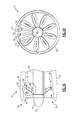
- Figure 1A illustrates a partial side view of an air intake for a gas turbine engine 10.
- Figure 1B illustrates a front view of the gas turbine engine 10 with a cutout view 60 illustrating the fan exit guide vanes 50 behind the fan blades 30.
- the gas turbine engine 10 has an air intake fan 40 that rotates fan blades 30 radially about an axis A.
- the rotation of the fan blades 30 draws air into the gas turbine engine 10 along a flow path 32.
- the fan 40 is encased in a fan case 20, such as a turbine engine shroud. As the air passes through the fan blades 30, the air begins swirling radially relative to axis A due to the rotation of the fan blades 30.
- each of the structural fan exit guide vane segments 50 includes multiple foil shaped guide vanes 52.
- Each guide vane 52 is connected to an inner diameter shroud 58 and an outer diameter shroud 56.
- Each of the outer diameter shrouds 56 are connected to the fan case 20.
- Each of the inner diameter shrouds 58 are connected to an engine core 42.
- the structural fan exit guide vanes 50 provide structural support to the engine core 42 and the fan case 20, thereby ensuring that proper clearance is maintained between the tips of the fan blades 30 and the fan case 20. Additionally, the structural support of the structural fan exit guide vane segments 50 maintains the concentricness of the engine core 42, the fan blades 30, and the fan case 20.
- FIG. 1B illustrates a front view of the gas turbine engine 10, with a cutout segment 60 illustrating the structural fan exit guide vane segments 50 positioned axially behind the fan blades 30.
- Each of the structural fan exit guide vanes segments 50 includes a first exit guide vane 52 and a second exit guide vane 54.
- the outer diameter shroud 56 of each structural fan exit guide vane segment 50 abuts the outer diameter shrouds of each adjacent structural fan exit guide vane segment 50 resulting in a circular structural fan exit guide vane segment assembly behind the fan blades 30.
- the structural fan exit guide vane assembly structurally supports the engine core 42, the fan blades 30, and the fan case 20 and axially straightens the flow path 32.
- each of the inner diameter shrouds 58 abuts the inner diameter shrouds 58 of each adjacent structural fan exit guide vane segment 50.
- each structural fan exit guide vane segment 50 abutting two adjacent fan exit guide vane segments 50 creates a circular structural fan exit guide vane assembly that provides the structural support described above, and the airflow straightening described above, while at the same time not requiring a separate structural frame assembly to support the fan 40, the fan case 20, and the engine core 42.
- FIG. 2 illustrates a more detailed contextual side drawing of a single structural fan exit guide vane 100.
- the outer diameter shroud 156 and the inner diameter shroud 158 of the structural fan exit guide vane 100 are connected by guide vanes 152, 154.
- Each of the shrouds 156, 158 is fastened to the fan case 20 and the engine case 42 via a plurality of fasteners 170, such as bolts.
- the fasteners 170 protrude through the shrouds 156, 158 and into the fan case 20 and the engine core 42.
- Each of the inner diameter shroud 158 and the outer diameter shroud 156 also includes a fiber bulge 160, resulting from the molding process, that physically contacts the fan case 20 (in the case of the outer diameter shroud 156) and the engine core 42 (in the case of the inner diameter shroud 158).
- FIG 3A illustrates an isometric view of a structural fan exit guide vane segment 200 that can be used as the structural fan exit guide vane segment 50 of Figures 1A and 1B .
- the structural fan exit guide vane segment 200 includes an arced outer diameter shroud 256 and an arced inner diameter shroud 258 with each of the arcs being coaxial.
- the shrouds 256, 258 are connected via two fan exit guide vanes 252, 254.
- Each of the shrouds 256, 258 also includes multiple counter sunk holes 272 for fastening the shrouds 256, 258 to the fan case 20 and the engine core 42.
- the arcing of the shrouds is concentric.
- the countersinking of the fastener bolts allows the fastener heads to be flush with the exposed surface of the shrouds 256, 258, thereby minimizing the effect of the fasteners on the airflow along the flow path 32 through the gas turbine engine 10.
- integral flow path spacer 280 Also attached to both the inner and the outer diameter shrouds 256, 258 is an integral flow path spacer 280.
- the integral flow path spacer 280 on the outer diameter shroud 256 is visible in Figure 3A , while the integral flow path spacer 280 on the inner diameter shroud 258 is hidden due to the view angle.
- the integral flow path spacer 280 provides an airflow seal between each structural guide vane 200 and the adjacent structural guide vanes 200.
- the integral flow path spacer 280 is only placed on a single shroud edge of each of the inner and outer diameter shrouds 256, 258.
- each shroud edge with a spacer abuts an edge of an adjacent shroud 256, 258 without a spacer resulting in each abutment being sealed by a single integral flow path spacer 280.
- Each of the guide vanes 252, 254 has an airfoil shaped profile that allows the vanes 252, 254 to force air passing through the structural fan exit guide vane assembly into an axial flow path.
- the particular foil profile of the vanes 252, 254 can be designed according to known techniques to fit the requirements of a particular gas turbine engine implementation.
- Figure 3B illustrates an alternate viewpoint of the structural guide vane assembly of Figure 3A , with like numerals indicating like elements.
- the view shown in Figure 3B shows the integral flow path spacer 280 on each of the inner and outer diameter shrouds 256, 258. Also illustrated is the fiber bulge 260 on the inner diameter shroud 256.
- the isometric view of Figure 3B further illustrates the foil profile of the guide vanes 252, 254.
- Figure 4 provides a zoomed isometric view of the outer diameter shroud 256 and the integral flow path spacer 280 of Figures 3A and 3B .
- the integral flow path spacer 280 is a solid piece of flexible material, such as rubber, and includes a seal portion 282 and a connection portion 284.
- the seal portion 282 overhangs the edge of the outer diameter shroud 258.
- the seal portion 282 deforms to provide an airtight seal between the two outer diameter shrouds 256.
- the seal portion 282 also provides vibrational damping between the structural guide vane segments 200.
- connection portion 284 of the integral flow path spacer 280 is affixed to the shroud segment, attaching the integral flow path spacer 282 to the shroud.
- a similar integral flow path spacer 282 design is used with the inner diameter shroud 258.
- the structural fan exit guide vane segments described above and illustrated in the figures use a single monolithic carbon/epoxy structure to construct the guide vane segment as a single piece.
- the two vanes are shaped into a preform having the desired airfoil profile using a continuous or semi-continuous fiber.
- the fiber preform is then infused with a carbon/epoxy resin during a molding process.
- This type of resin molding generates an end component that is a single piece and is constructed of a fiber reinforced polymer matrix composite.
- the molding process also creates the inner and outer diameter shrouds using standard carbon/epoxy laminate molding processes.
- the counter sunk holes can either be created as part of the molding process or drilled after the molding process is finished.
- three or more guide vanes can be constructed in the same manner, and could be used in each monolithic vane segment and still fall within the above disclosure.
Landscapes
- Engineering & Computer Science (AREA)
- Mechanical Engineering (AREA)
- General Engineering & Computer Science (AREA)
- Structures Of Non-Positive Displacement Pumps (AREA)
Abstract
Description
- The present disclosure is directed toward turbomachine assemblies and more particularly, toward a structural fan exit guide vane for use in a gas turbine engine.
- Turbomachines, such as gas turbine engines, draw air or other gases into the machine using a fan component. The rotation of the fan blades drawing the air in causes the incoming air to swirl in the direction of the fan's rotation. In order to operate the turbomachine properly, however, the air must pass axially through the turbomachine. To rectify the radial swirling of the air, turbomachines include fan exit guide vanes that straighten the air flow behind the fan blades.
- Fan exit guide vanes assemblies include multiple vanes, each of which has an airfoil shaped profile that is aerodynamically designed to force the airflow passing through the fan exit guide vane into an axial flow path. Also included within turbomachine assemblies is a separate fan frame that supports the engine core, the fan, and the fan case. The fan frame also maintains the concentricness of the fan case, and the fan blades, and the engine core, thus providing for proper fan tip clearance between the engine shroud and the fan blades.
- A structural composite fan exit guide vane segment according to a first aspect of the invention includes a single monolithic component having an inner diameter shroud, an outer diameter shroud, and a plurality of fan exit guide vanes connecting the inner diameter shroud and the outer diameter shroud.
- A gas turbine engine according to a further aspect of the invention has a fan frame composed of a plurality of fan exit guide vane segments. Each of the fan exit guide vane segments has a single monolithic component with an inner diameter shroud, an outer diameter shroud, and a plurality of fan exit guide vanes connecting the inner diameter shroud and the outer diameter shroud.
- A method is disclosed for creating a fan exit guide vane segment that includes the steps of creating a semi-continuous fiber preform by looping fibers in a desired profile, and infusing the fiber preform with a resin during a molding process thereby creating a single monolithic fan exit guide vane segment.
-
-
Figure 1A illustrates a partial side view of an air intake for the gas turbine engine ofFigure 1A . -
Figure 1B illustrates a front view of the air intake for a gas turbine engine. -
Figure 2 is a contextual drawing of a structural fan exit guide vane assembly. -
Figure 3A illustrates a first isometric view of a structural fan exit guide vane segment. -
Figure 3B illustrates a second isometric view of the structural fan exit guide vane segment ofFigure 3A . -
Figure 4 illustrates a partial isometric view of a fan exit guide vane assembly outer diameter shroud. -
Figure 1A illustrates a partial side view of an air intake for agas turbine engine 10.Figure 1B illustrates a front view of thegas turbine engine 10 with acutout view 60 illustrating the fan exit guide vanes 50 behind thefan blades 30. - Referring to
Figure 1A , thegas turbine engine 10 has anair intake fan 40 that rotatesfan blades 30 radially about an axis A. The rotation of thefan blades 30 draws air into thegas turbine engine 10 along aflow path 32. Thefan 40 is encased in afan case 20, such as a turbine engine shroud. As the air passes through thefan blades 30, the air begins swirling radially relative to axis A due to the rotation of thefan blades 30. - In order to straighten the
flow path 32, and allow the air to flow axially through thegas turbine engine 10, the air is passed through a multiple of structural fan exitguide vane segments 50. Each of the structural fan exitguide vane segments 50 includes multiple foilshaped guide vanes 52. Eachguide vane 52 is connected to an inner diameter shroud 58 and anouter diameter shroud 56. Each of theouter diameter shrouds 56 are connected to thefan case 20. Each of the inner diameter shrouds 58 are connected to anengine core 42. - In addition to straightening the
flow path 32 through thegas turbine engine 10, the structural fan exit guide vanes 50 provide structural support to theengine core 42 and thefan case 20, thereby ensuring that proper clearance is maintained between the tips of thefan blades 30 and thefan case 20. Additionally, the structural support of the structural fan exitguide vane segments 50 maintains the concentricness of theengine core 42, thefan blades 30, and thefan case 20. -
Figure 1B illustrates a front view of thegas turbine engine 10, with acutout segment 60 illustrating the structural fan exitguide vane segments 50 positioned axially behind thefan blades 30. Each of the structural fan exitguide vanes segments 50 includes a firstexit guide vane 52 and a secondexit guide vane 54. Theouter diameter shroud 56 of each structural fan exitguide vane segment 50 abuts the outer diameter shrouds of each adjacent structural fan exitguide vane segment 50 resulting in a circular structural fan exit guide vane segment assembly behind thefan blades 30. The structural fan exit guide vane assembly structurally supports theengine core 42, thefan blades 30, and thefan case 20 and axially straightens theflow path 32. As with theouter diameter shrouds 56, each of the inner diameter shrouds 58 abuts the inner diameter shrouds 58 of each adjacent structural fan exitguide vane segment 50. - The above described configuration with each structural fan exit
guide vane segment 50 abutting two adjacent fan exitguide vane segments 50 creates a circular structural fan exit guide vane assembly that provides the structural support described above, and the airflow straightening described above, while at the same time not requiring a separate structural frame assembly to support thefan 40, thefan case 20, and theengine core 42. -
Figure 2 illustrates a more detailed contextual side drawing of a single structural fanexit guide vane 100. Theouter diameter shroud 156 and theinner diameter shroud 158 of the structural fanexit guide vane 100 are connected by guide vanes 152, 154. Each of theshrouds fan case 20 and theengine case 42 via a plurality offasteners 170, such as bolts. Thefasteners 170 protrude through theshrouds fan case 20 and theengine core 42. Each of theinner diameter shroud 158 and theouter diameter shroud 156 also includes afiber bulge 160, resulting from the molding process, that physically contacts the fan case 20 (in the case of the outer diameter shroud 156) and the engine core 42 (in the case of the inner diameter shroud 158). -
Figure 3A illustrates an isometric view of a structural fan exitguide vane segment 200 that can be used as the structural fan exitguide vane segment 50 ofFigures 1A and 1B . The structural fan exitguide vane segment 200 includes an arcedouter diameter shroud 256 and an arcedinner diameter shroud 258 with each of the arcs being coaxial. Theshrouds exit guide vanes shrouds counter sunk holes 272 for fastening theshrouds fan case 20 and theengine core 42. The arcing of the shrouds is concentric. The countersinking of the fastener bolts allows the fastener heads to be flush with the exposed surface of theshrouds flow path 32 through thegas turbine engine 10. - Also attached to both the inner and the
outer diameter shrouds flow path spacer 280. The integralflow path spacer 280 on theouter diameter shroud 256 is visible inFigure 3A , while the integralflow path spacer 280 on theinner diameter shroud 258 is hidden due to the view angle. The integralflow path spacer 280 provides an airflow seal between eachstructural guide vane 200 and the adjacentstructural guide vanes 200. - Due to the circular nature of the structural guide vane assembly, the integral
flow path spacer 280 is only placed on a single shroud edge of each of the inner andouter diameter shrouds adjacent shroud flow path spacer 280. - Each of the
guide vanes vanes vanes -
Figure 3B illustrates an alternate viewpoint of the structural guide vane assembly ofFigure 3A , with like numerals indicating like elements. The view shown inFigure 3B shows the integralflow path spacer 280 on each of the inner andouter diameter shrouds fiber bulge 260 on theinner diameter shroud 256. The isometric view ofFigure 3B further illustrates the foil profile of theguide vanes -
Figure 4 provides a zoomed isometric view of theouter diameter shroud 256 and the integralflow path spacer 280 ofFigures 3A and 3B . The integralflow path spacer 280 is a solid piece of flexible material, such as rubber, and includes aseal portion 282 and aconnection portion 284. Theseal portion 282 overhangs the edge of theouter diameter shroud 258. When the structuralguide vane segment 200 abuts an adjacent guide vane segment, theseal portion 282 deforms to provide an airtight seal between the two outer diameter shrouds 256. Theseal portion 282 also provides vibrational damping between the structuralguide vane segments 200. Theconnection portion 284 of the integral flow path spacer 280 is affixed to the shroud segment, attaching the integral flow path spacer 282 to the shroud. A similar integral flow path spacer 282 design is used with theinner diameter shroud 258. - The structural fan exit guide vane segments described above and illustrated in the figures, use a single monolithic carbon/epoxy structure to construct the guide vane segment as a single piece. In order to create the single monolithic guide vane segment, the two vanes are shaped into a preform having the desired airfoil profile using a continuous or semi-continuous fiber. The fiber preform is then infused with a carbon/epoxy resin during a molding process. This type of resin molding generates an end component that is a single piece and is constructed of a fiber reinforced polymer matrix composite. The molding process also creates the inner and outer diameter shrouds using standard carbon/epoxy laminate molding processes. The counter sunk holes can either be created as part of the molding process or drilled after the molding process is finished. In an alternative example, three or more guide vanes can be constructed in the same manner, and could be used in each monolithic vane segment and still fall within the above disclosure.
- Although embodiments of this invention have been disclosed, a worker of ordinary skill would recognize that certain modifications would come within the scope of this invention. For that reason, the following claims should be studied to determine the true scope and content of this invention.
Claims (15)
- A structural composite fan exit guide vane segment (200) comprising:a monolithic component having an inner diameter shroud (258);an outer diameter shroud (256); anda plurality of fan exit guide vanes (252,254) connecting said inner diameter shroud (258) and said outer diameter shroud (256).
- The structural composite fan exit guide vane segment of claim 1, wherein said monolithic component (200) is constructed of a composite material, said composite material comprising, for example, a carbon/epoxy laminate molding.
- The structural composite fan exit guide vane segment of claim 1 or 2, wherein said inner diameter shroud (258) comprises at least one counter sunk hole (272) operable to connect said inner diameter shroud (258) to an engine frame (42).
- The structural composite fan exit guide vane segment of any preceding claim, wherein said outer diameter shroud (256) comprises at least one counter sunk hole (272) operable to connect said outer diameter shroud (256) to an engine casing (20).
- The structural composite fan exit guide vane segment of any preceding claim, further comprising an integral flow path spacer (280) affixed to a single side of said outer diameter shroud (256) and/or of said inner diameter shroud (258).
- The structural composite fan exit guide vane segment of any preceding claim, wherein each of said fan exit guide vanes (252;254) has an airfoil shaped profile.
- The structural composite fan exit guide vane segment of any preceding claim, wherein said plurality of fan exit guide vanes (252;254) comprises exactly two fan exit guide vanes (252;254).
- The structural composite fan exit guide vane segment of any preceding claim, wherein said plurality of fan exit guide vanes (252;254) comprise a fiber reinforced polymer matrix composite.
- The structural composite fan exit guide vane segment of any preceding claim, wherein said inner diameter shroud (258) is an arc segment having a first radius, said outer diameter shroud (256) is an arc segment having an second radius, and said second radius is larger than said first radius.
- A gas turbine engine comprising;
a fan (40); and
a fan frame supporting said fan (40); said fan frame comprising a plurality of fan exit guide vane segments (200) of any preceding claim. - The gas turbine engine of claim 10, wherein said inner diameter shroud (258) comprises a plurality of counter sunk holes (272), a fastener protruding through each of said plurality of counter sunk holes (272) thereby fastening said fan exit guide vane segment (200) to said frame; and/or wherein said outer diameter shroud (256) comprises a plurality of counter sunk holes (272), a fastener protruding through each of said plurality of counter sunk holes (272) thereby fastening said fan exit guide vane segment (200) to an engine casing (42), wherein, optionally a head of each said fastener is flush with such counter sunk holes (272).
- The gas turbine engine of claim 10 or 11, wherein each of said plurality of fan exit guide segments (200) abuts at least two adjacent fan exit guide vane segments (200).
- The gas turbine engine of claim 12, further comprising an integral flow path spacer (280) operable to create a seal between each abutting outer diameter shroud (256) and/or further comprising an integral flow path spacer (280) operable to create a seal between each abutting inner diameter shroud (258).
- The gas turbine engine of any of claims 10 to 13, wherein each of said plurality of fan exit guide vanes segments (200) structurally supports said gas turbine engine, for example wherein said gas turbine engine is structurally supported at a gas exit via only said fan exit guide vane segments (200).
- A method for creating a fan exit guide vane segment comprising the steps of creating a fiber preform by looping a fiber in a desired profile; and
infusing said fiber preform with a resin during a molding process thereby creating a single monolithic fan exit guide vane segment (200);
wherein, optionally, said looped fiber is substantially a structurally continuous loop or substantially a structurally semi-continuous loop; and/or
wherein, optionally, said resin is a carbon/epoxy resin.
Applications Claiming Priority (1)
| Application Number | Priority Date | Filing Date | Title |
|---|---|---|---|
| US13/217,372 US20130052004A1 (en) | 2011-08-25 | 2011-08-25 | Structural composite fan exit guide vane for a turbomachine |
Publications (3)
| Publication Number | Publication Date |
|---|---|
| EP2562361A1 true EP2562361A1 (en) | 2013-02-27 |
| EP2562361B1 EP2562361B1 (en) | 2015-12-09 |
| EP2562361B2 EP2562361B2 (en) | 2019-04-10 |
Family
ID=46750230
Family Applications (1)
| Application Number | Title | Priority Date | Filing Date |
|---|---|---|---|
| EP12181806.6A Active EP2562361B2 (en) | 2011-08-25 | 2012-08-24 | Structural composite fan exit guide vane for a turbomachine |
Country Status (2)
| Country | Link |
|---|---|
| US (1) | US20130052004A1 (en) |
| EP (1) | EP2562361B2 (en) |
Cited By (5)
| Publication number | Priority date | Publication date | Assignee | Title |
|---|---|---|---|---|
| FR3003668A1 (en) * | 2013-03-25 | 2014-09-26 | Snecma | METHOD FOR DESIGNING A COMMON PREFORM FOR PRODUCING TURBOMACHINE OUTPUT GUIDE PREFORMS IN COMPOSITE MATERIAL WITH DIFFERENT GEOMETRIC PROFILES |
| US9303531B2 (en) | 2011-12-09 | 2016-04-05 | General Electric Company | Quick engine change assembly for outlet guide vanes |
| US9303520B2 (en) | 2011-12-09 | 2016-04-05 | General Electric Company | Double fan outlet guide vane with structural platforms |
| EP3124751A1 (en) * | 2015-07-28 | 2017-02-01 | Rolls-Royce plc | A nozzle guide vane passage |
| US10724390B2 (en) | 2018-03-16 | 2020-07-28 | General Electric Company | Collar support assembly for airfoils |
Families Citing this family (15)
| Publication number | Priority date | Publication date | Assignee | Title |
|---|---|---|---|---|
| US20130149130A1 (en) * | 2011-12-09 | 2013-06-13 | General Electric Company | Fan Hub Frame for Double Outlet Guide Vane |
| EP2735706B8 (en) * | 2012-11-21 | 2016-12-07 | Safran Aero Booster S.A. | Vane diffuser of an axial turbomachine compressor and method for manufacturing same |
| US20160146104A1 (en) * | 2013-07-08 | 2016-05-26 | United Technologies Corporation | Angled Core Engine |
| FR3021714B1 (en) * | 2014-06-02 | 2016-06-24 | Snecma | VANE FIXING ORIFICE SHUTTER FROM A TURBOMACHINE RECTIFIER |
| US10589475B2 (en) | 2014-09-23 | 2020-03-17 | General Electric Company | Braided blades and vanes having dovetail roots |
| US10047763B2 (en) * | 2015-12-14 | 2018-08-14 | General Electric Company | Rotor assembly for use in a turbofan engine and method of assembling |
| US10774788B2 (en) * | 2016-06-28 | 2020-09-15 | Raytheon Technologies Corporation | Particle extraction system for a gas turbine engine |
| US10385868B2 (en) * | 2016-07-05 | 2019-08-20 | General Electric Company | Strut assembly for an aircraft engine |
| US10570917B2 (en) | 2016-08-01 | 2020-02-25 | United Technologies Corporation | Fan blade with composite cover |
| FR3056250B1 (en) * | 2016-09-19 | 2020-06-05 | Safran Aircraft Engines | VANE WHEEL RECTIFIER IN INTERMEDIATE HOUSING |
| US10443625B2 (en) * | 2016-09-21 | 2019-10-15 | General Electric Company | Airfoil singlets |
| US10483659B1 (en) * | 2018-11-19 | 2019-11-19 | United Technologies Corporation | Grounding clip for bonded vanes |
| FR3091723B1 (en) * | 2019-01-15 | 2021-04-02 | Safran Aircraft Engines | Composite blade or propeller blade for aircraft incorporating a shaping part |
| FR3134598B1 (en) * | 2022-04-15 | 2024-04-05 | Safran Aircraft Engines | Fixed blade made of composite materials fixed radially on a fixed structure of a turbomachine |
| FR3166179A1 (en) * | 2024-09-12 | 2026-03-13 | Safran Aircraft Engines | BLOWER SECTION WITH DEFORMABLE SEAL |
Citations (5)
| Publication number | Priority date | Publication date | Assignee | Title |
|---|---|---|---|---|
| WO1991015357A1 (en) * | 1990-03-30 | 1991-10-17 | Courtaulds Plc | Preform and composite structure |
| EP0513958A2 (en) * | 1991-05-13 | 1992-11-19 | General Electric Company | Composite fan stator assembly |
| EP0654586A1 (en) * | 1993-11-19 | 1995-05-24 | United Technologies Corporation | Stator vane assembly |
| US20030185673A1 (en) * | 2002-01-21 | 2003-10-02 | Honda Giken Kogyo Kabushiki Kaisha | Flow-rectifying member and its unit and method for producing flow-rectifying member |
| US20060113706A1 (en) * | 2003-03-26 | 2006-06-01 | Jean-Pierre Chevin | Method of producing polyimide matrix composite parts |
Family Cites Families (9)
| Publication number | Priority date | Publication date | Assignee | Title |
|---|---|---|---|---|
| US2942843A (en) * | 1956-06-15 | 1960-06-28 | Westinghouse Electric Corp | Blade vibration damping structure |
| GB1237532A (en) * | 1967-06-24 | 1971-06-30 | Rolls Royce | Improvements in turbines and compresser rotors |
| GB2161110B (en) * | 1984-07-07 | 1988-03-23 | Rolls Royce | An annular bladed member having an integral shroud and a method of manufacture thereof |
| US5722813A (en) * | 1996-10-28 | 1998-03-03 | Alliedsignal Inc. | Segmented composite compressor deswirl |
| DE69815815T2 (en) † | 1998-05-01 | 2004-05-13 | Techspace Aero, Milmort | Guide blades for a turbomachine |
| US7645120B2 (en) * | 2005-04-27 | 2010-01-12 | Honda Motor Co., Ltd. | Flow-guiding member unit and its production method |
| AT503840B1 (en) † | 2006-06-30 | 2010-09-15 | Facc Ag | ROD ROD ARRANGEMENT FOR A TRANSMISSION |
| EP2339120B1 (en) † | 2009-12-22 | 2015-07-08 | Techspace Aero S.A. | Turbomachine stator stage and corresponding compressor |
| US8105039B1 (en) * | 2011-04-01 | 2012-01-31 | United Technologies Corp. | Airfoil tip shroud damper |
-
2011
- 2011-08-25 US US13/217,372 patent/US20130052004A1/en not_active Abandoned
-
2012
- 2012-08-24 EP EP12181806.6A patent/EP2562361B2/en active Active
Patent Citations (5)
| Publication number | Priority date | Publication date | Assignee | Title |
|---|---|---|---|---|
| WO1991015357A1 (en) * | 1990-03-30 | 1991-10-17 | Courtaulds Plc | Preform and composite structure |
| EP0513958A2 (en) * | 1991-05-13 | 1992-11-19 | General Electric Company | Composite fan stator assembly |
| EP0654586A1 (en) * | 1993-11-19 | 1995-05-24 | United Technologies Corporation | Stator vane assembly |
| US20030185673A1 (en) * | 2002-01-21 | 2003-10-02 | Honda Giken Kogyo Kabushiki Kaisha | Flow-rectifying member and its unit and method for producing flow-rectifying member |
| US20060113706A1 (en) * | 2003-03-26 | 2006-06-01 | Jean-Pierre Chevin | Method of producing polyimide matrix composite parts |
Cited By (8)
| Publication number | Priority date | Publication date | Assignee | Title |
|---|---|---|---|---|
| US9303531B2 (en) | 2011-12-09 | 2016-04-05 | General Electric Company | Quick engine change assembly for outlet guide vanes |
| US9303520B2 (en) | 2011-12-09 | 2016-04-05 | General Electric Company | Double fan outlet guide vane with structural platforms |
| FR3003668A1 (en) * | 2013-03-25 | 2014-09-26 | Snecma | METHOD FOR DESIGNING A COMMON PREFORM FOR PRODUCING TURBOMACHINE OUTPUT GUIDE PREFORMS IN COMPOSITE MATERIAL WITH DIFFERENT GEOMETRIC PROFILES |
| WO2014154981A1 (en) * | 2013-03-25 | 2014-10-02 | Snecma | Method of designing a common preform for producing preforms of guide vanes of a turbine engine outlet, made of a composite material having different geometric profiles |
| US10019549B2 (en) | 2013-03-25 | 2018-07-10 | Snecma | Method of designing a common preform for providing preforms for turbine engine outlet guide vanes of different geometrical profiles and made out of composite material |
| EP3124751A1 (en) * | 2015-07-28 | 2017-02-01 | Rolls-Royce plc | A nozzle guide vane passage |
| US10370988B2 (en) | 2015-07-28 | 2019-08-06 | Rolls-Royce Plc | Nozzle guide vane passage |
| US10724390B2 (en) | 2018-03-16 | 2020-07-28 | General Electric Company | Collar support assembly for airfoils |
Also Published As
| Publication number | Publication date |
|---|---|
| US20130052004A1 (en) | 2013-02-28 |
| EP2562361B2 (en) | 2019-04-10 |
| EP2562361B1 (en) | 2015-12-09 |
Similar Documents
| Publication | Publication Date | Title |
|---|---|---|
| EP2562361A1 (en) | Structural composite fan exit guide vane for a turbomachine | |
| US8182209B2 (en) | Air reinjection compressor | |
| US8529204B2 (en) | Gas turbine engine having a nose cone assembly rigidly attached in an axial direction but flexible in a radial direction | |
| EP2811144B1 (en) | Fan rotor blade of aircraft jet engine | |
| US10358929B2 (en) | Composite airfoil | |
| CA2725238C (en) | Architecture of a compressor rectifier | |
| US9482095B2 (en) | Web connected dual aerofoil members | |
| US7530782B2 (en) | Foreign object damage resistant vane assembly | |
| US8152461B2 (en) | Integrated inlet design | |
| EP2811138B1 (en) | Vane coupling part structure and jet engine using same | |
| EP2811143B1 (en) | Fan rotor blade of aircraft jet engine | |
| EP1924758B1 (en) | Vane assembly with outer grommets | |
| US10507904B2 (en) | Snap fit nose cone assembly | |
| US20150192140A1 (en) | Composite Housing with a Metallic Flange for the Compressor of an Axial Turbomachine | |
| US10738630B2 (en) | Platform apparatus for propulsion rotor | |
| JP5823493B2 (en) | Turbomachinery rectifier | |
| CA2622017C (en) | Vane assembly with improved vane roots | |
| US12535007B2 (en) | Cover plate connections for a hollow fan blade | |
| US7413400B2 (en) | Vane assembly with grommet | |
| US10344672B2 (en) | Low weight nose cone assembly | |
| JP4820373B2 (en) | Static gas turbine components and methods for repairing such components | |
| US9951654B2 (en) | Stator blade sector for an axial turbomachine with a dual means of fixing | |
| EP2865879B1 (en) | Vane linking portion structure, and jet engine using same | |
| EP2562368A2 (en) | Rotor asymmetry | |
| EP3140517B1 (en) | Composite booster spool with separable composite blades |
Legal Events
| Date | Code | Title | Description |
|---|---|---|---|
| PUAI | Public reference made under article 153(3) epc to a published international application that has entered the european phase |
Free format text: ORIGINAL CODE: 0009012 |
|
| AK | Designated contracting states |
Kind code of ref document: A1 Designated state(s): AL AT BE BG CH CY CZ DE DK EE ES FI FR GB GR HR HU IE IS IT LI LT LU LV MC MK MT NL NO PL PT RO RS SE SI SK SM TR |
|
| AX | Request for extension of the european patent |
Extension state: BA ME |
|
| 17P | Request for examination filed |
Effective date: 20130814 |
|
| RBV | Designated contracting states (corrected) |
Designated state(s): AL AT BE BG CH CY CZ DE DK EE ES FI FR GB GR HR HU IE IS IT LI LT LU LV MC MK MT NL NO PL PT RO RS SE SI SK SM TR |
|
| 17Q | First examination report despatched |
Effective date: 20141217 |
|
| GRAP | Despatch of communication of intention to grant a patent |
Free format text: ORIGINAL CODE: EPIDOSNIGR1 |
|
| INTG | Intention to grant announced |
Effective date: 20150701 |
|
| GRAS | Grant fee paid |
Free format text: ORIGINAL CODE: EPIDOSNIGR3 |
|
| GRAA | (expected) grant |
Free format text: ORIGINAL CODE: 0009210 |
|
| AK | Designated contracting states |
Kind code of ref document: B1 Designated state(s): AL AT BE BG CH CY CZ DE DK EE ES FI FR GB GR HR HU IE IS IT LI LT LU LV MC MK MT NL NO PL PT RO RS SE SI SK SM TR |
|
| REG | Reference to a national code |
Ref country code: GB Ref legal event code: FG4D |
|
| REG | Reference to a national code |
Ref country code: AT Ref legal event code: REF Ref document number: 764671 Country of ref document: AT Kind code of ref document: T Effective date: 20151215 Ref country code: CH Ref legal event code: EP |
|
| REG | Reference to a national code |
Ref country code: IE Ref legal event code: FG4D |
|
| REG | Reference to a national code |
Ref country code: DE Ref legal event code: R096 Ref document number: 602012012842 Country of ref document: DE |
|
| REG | Reference to a national code |
Ref country code: LT Ref legal event code: MG4D |
|
| REG | Reference to a national code |
Ref country code: NL Ref legal event code: MP Effective date: 20151209 |
|
| PG25 | Lapsed in a contracting state [announced via postgrant information from national office to epo] |
Ref country code: LT Free format text: LAPSE BECAUSE OF FAILURE TO SUBMIT A TRANSLATION OF THE DESCRIPTION OR TO PAY THE FEE WITHIN THE PRESCRIBED TIME-LIMIT Effective date: 20151209 Ref country code: NO Free format text: LAPSE BECAUSE OF FAILURE TO SUBMIT A TRANSLATION OF THE DESCRIPTION OR TO PAY THE FEE WITHIN THE PRESCRIBED TIME-LIMIT Effective date: 20160309 Ref country code: ES Free format text: LAPSE BECAUSE OF FAILURE TO SUBMIT A TRANSLATION OF THE DESCRIPTION OR TO PAY THE FEE WITHIN THE PRESCRIBED TIME-LIMIT Effective date: 20151209 |
|
| REG | Reference to a national code |
Ref country code: AT Ref legal event code: MK05 Ref document number: 764671 Country of ref document: AT Kind code of ref document: T Effective date: 20151209 |
|
| PG25 | Lapsed in a contracting state [announced via postgrant information from national office to epo] |
Ref country code: SE Free format text: LAPSE BECAUSE OF FAILURE TO SUBMIT A TRANSLATION OF THE DESCRIPTION OR TO PAY THE FEE WITHIN THE PRESCRIBED TIME-LIMIT Effective date: 20151209 Ref country code: NL Free format text: LAPSE BECAUSE OF FAILURE TO SUBMIT A TRANSLATION OF THE DESCRIPTION OR TO PAY THE FEE WITHIN THE PRESCRIBED TIME-LIMIT Effective date: 20151209 Ref country code: GR Free format text: LAPSE BECAUSE OF FAILURE TO SUBMIT A TRANSLATION OF THE DESCRIPTION OR TO PAY THE FEE WITHIN THE PRESCRIBED TIME-LIMIT Effective date: 20160310 Ref country code: FI Free format text: LAPSE BECAUSE OF FAILURE TO SUBMIT A TRANSLATION OF THE DESCRIPTION OR TO PAY THE FEE WITHIN THE PRESCRIBED TIME-LIMIT Effective date: 20151209 Ref country code: RS Free format text: LAPSE BECAUSE OF FAILURE TO SUBMIT A TRANSLATION OF THE DESCRIPTION OR TO PAY THE FEE WITHIN THE PRESCRIBED TIME-LIMIT Effective date: 20151209 Ref country code: LV Free format text: LAPSE BECAUSE OF FAILURE TO SUBMIT A TRANSLATION OF THE DESCRIPTION OR TO PAY THE FEE WITHIN THE PRESCRIBED TIME-LIMIT Effective date: 20151209 |
|
| PG25 | Lapsed in a contracting state [announced via postgrant information from national office to epo] |
Ref country code: IS Free format text: LAPSE BECAUSE OF FAILURE TO SUBMIT A TRANSLATION OF THE DESCRIPTION OR TO PAY THE FEE WITHIN THE PRESCRIBED TIME-LIMIT Effective date: 20151209 |
|
| PG25 | Lapsed in a contracting state [announced via postgrant information from national office to epo] |
Ref country code: IT Free format text: LAPSE BECAUSE OF FAILURE TO SUBMIT A TRANSLATION OF THE DESCRIPTION OR TO PAY THE FEE WITHIN THE PRESCRIBED TIME-LIMIT Effective date: 20151209 Ref country code: CZ Free format text: LAPSE BECAUSE OF FAILURE TO SUBMIT A TRANSLATION OF THE DESCRIPTION OR TO PAY THE FEE WITHIN THE PRESCRIBED TIME-LIMIT Effective date: 20151209 |
|
| PG25 | Lapsed in a contracting state [announced via postgrant information from national office to epo] |
Ref country code: PT Free format text: LAPSE BECAUSE OF FAILURE TO SUBMIT A TRANSLATION OF THE DESCRIPTION OR TO PAY THE FEE WITHIN THE PRESCRIBED TIME-LIMIT Effective date: 20160411 Ref country code: IS Free format text: LAPSE BECAUSE OF FAILURE TO SUBMIT A TRANSLATION OF THE DESCRIPTION OR TO PAY THE FEE WITHIN THE PRESCRIBED TIME-LIMIT Effective date: 20160409 Ref country code: SM Free format text: LAPSE BECAUSE OF FAILURE TO SUBMIT A TRANSLATION OF THE DESCRIPTION OR TO PAY THE FEE WITHIN THE PRESCRIBED TIME-LIMIT Effective date: 20151209 Ref country code: EE Free format text: LAPSE BECAUSE OF FAILURE TO SUBMIT A TRANSLATION OF THE DESCRIPTION OR TO PAY THE FEE WITHIN THE PRESCRIBED TIME-LIMIT Effective date: 20151209 Ref country code: AT Free format text: LAPSE BECAUSE OF FAILURE TO SUBMIT A TRANSLATION OF THE DESCRIPTION OR TO PAY THE FEE WITHIN THE PRESCRIBED TIME-LIMIT Effective date: 20151209 Ref country code: SK Free format text: LAPSE BECAUSE OF FAILURE TO SUBMIT A TRANSLATION OF THE DESCRIPTION OR TO PAY THE FEE WITHIN THE PRESCRIBED TIME-LIMIT Effective date: 20151209 Ref country code: RO Free format text: LAPSE BECAUSE OF FAILURE TO SUBMIT A TRANSLATION OF THE DESCRIPTION OR TO PAY THE FEE WITHIN THE PRESCRIBED TIME-LIMIT Effective date: 20151209 |
|
| REG | Reference to a national code |
Ref country code: DE Ref legal event code: R026 Ref document number: 602012012842 Country of ref document: DE |
|
| PLBI | Opposition filed |
Free format text: ORIGINAL CODE: 0009260 |
|
| REG | Reference to a national code |
Ref country code: CH Ref legal event code: PCOW Free format text: NEW ADDRESS: 10 FARM SPRINGS RD., FARMINGTON, CT 06032 (US) |
|
| PLAX | Notice of opposition and request to file observation + time limit sent |
Free format text: ORIGINAL CODE: EPIDOSNOBS2 |
|
| 26 | Opposition filed |
Opponent name: SAFRAN AIRCRAFT ENGINES Effective date: 20160908 |
|
| RAP2 | Party data changed (patent owner data changed or rights of a patent transferred) |
Owner name: UNITED TECHNOLOGIES CORPORATION |
|
| REG | Reference to a national code |
Ref country code: FR Ref legal event code: PLFP Year of fee payment: 5 |
|
| PG25 | Lapsed in a contracting state [announced via postgrant information from national office to epo] |
Ref country code: DK Free format text: LAPSE BECAUSE OF FAILURE TO SUBMIT A TRANSLATION OF THE DESCRIPTION OR TO PAY THE FEE WITHIN THE PRESCRIBED TIME-LIMIT Effective date: 20151209 Ref country code: PL Free format text: LAPSE BECAUSE OF FAILURE TO SUBMIT A TRANSLATION OF THE DESCRIPTION OR TO PAY THE FEE WITHIN THE PRESCRIBED TIME-LIMIT Effective date: 20151209 |
|
| PG25 | Lapsed in a contracting state [announced via postgrant information from national office to epo] |
Ref country code: SI Free format text: LAPSE BECAUSE OF FAILURE TO SUBMIT A TRANSLATION OF THE DESCRIPTION OR TO PAY THE FEE WITHIN THE PRESCRIBED TIME-LIMIT Effective date: 20151209 |
|
| PG25 | Lapsed in a contracting state [announced via postgrant information from national office to epo] |
Ref country code: BE Free format text: LAPSE BECAUSE OF FAILURE TO SUBMIT A TRANSLATION OF THE DESCRIPTION OR TO PAY THE FEE WITHIN THE PRESCRIBED TIME-LIMIT Effective date: 20151209 |
|
| PLBB | Reply of patent proprietor to notice(s) of opposition received |
Free format text: ORIGINAL CODE: EPIDOSNOBS3 |
|
| PG25 | Lapsed in a contracting state [announced via postgrant information from national office to epo] |
Ref country code: MC Free format text: LAPSE BECAUSE OF FAILURE TO SUBMIT A TRANSLATION OF THE DESCRIPTION OR TO PAY THE FEE WITHIN THE PRESCRIBED TIME-LIMIT Effective date: 20151209 |
|
| REG | Reference to a national code |
Ref country code: CH Ref legal event code: PL |
|
| PG25 | Lapsed in a contracting state [announced via postgrant information from national office to epo] |
Ref country code: CH Free format text: LAPSE BECAUSE OF NON-PAYMENT OF DUE FEES Effective date: 20160831 Ref country code: LI Free format text: LAPSE BECAUSE OF NON-PAYMENT OF DUE FEES Effective date: 20160831 |
|
| REG | Reference to a national code |
Ref country code: IE Ref legal event code: MM4A |
|
| REG | Reference to a national code |
Ref country code: DE Ref legal event code: R082 Ref document number: 602012012842 Country of ref document: DE Representative=s name: SCHMITT-NILSON SCHRAUD WAIBEL WOHLFROM PATENTA, DE |
|
| REG | Reference to a national code |
Ref country code: FR Ref legal event code: PLFP Year of fee payment: 6 |
|
| REG | Reference to a national code |
Ref country code: DE Ref legal event code: R082 Ref document number: 602012012842 Country of ref document: DE Representative=s name: SCHMITT-NILSON SCHRAUD WAIBEL WOHLFROM PATENTA, DE Ref country code: DE Ref legal event code: R081 Ref document number: 602012012842 Country of ref document: DE Owner name: UNITED TECHNOLOGIES CORP. (N.D.GES.D. STAATES , US Free format text: FORMER OWNER: UNITED TECHNOLOGIES CORPORATION, HARTFORD, CONN., US |
|
| PG25 | Lapsed in a contracting state [announced via postgrant information from national office to epo] |
Ref country code: IE Free format text: LAPSE BECAUSE OF NON-PAYMENT OF DUE FEES Effective date: 20160824 |
|
| PG25 | Lapsed in a contracting state [announced via postgrant information from national office to epo] |
Ref country code: LU Free format text: LAPSE BECAUSE OF NON-PAYMENT OF DUE FEES Effective date: 20160824 |
|
| PG25 | Lapsed in a contracting state [announced via postgrant information from national office to epo] |
Ref country code: CY Free format text: LAPSE BECAUSE OF FAILURE TO SUBMIT A TRANSLATION OF THE DESCRIPTION OR TO PAY THE FEE WITHIN THE PRESCRIBED TIME-LIMIT Effective date: 20151209 Ref country code: HU Free format text: LAPSE BECAUSE OF FAILURE TO SUBMIT A TRANSLATION OF THE DESCRIPTION OR TO PAY THE FEE WITHIN THE PRESCRIBED TIME-LIMIT; INVALID AB INITIO Effective date: 20120824 |
|
| PG25 | Lapsed in a contracting state [announced via postgrant information from national office to epo] |
Ref country code: HR Free format text: LAPSE BECAUSE OF FAILURE TO SUBMIT A TRANSLATION OF THE DESCRIPTION OR TO PAY THE FEE WITHIN THE PRESCRIBED TIME-LIMIT Effective date: 20151209 Ref country code: TR Free format text: LAPSE BECAUSE OF FAILURE TO SUBMIT A TRANSLATION OF THE DESCRIPTION OR TO PAY THE FEE WITHIN THE PRESCRIBED TIME-LIMIT Effective date: 20151209 Ref country code: MT Free format text: LAPSE BECAUSE OF NON-PAYMENT OF DUE FEES Effective date: 20160831 Ref country code: MK Free format text: LAPSE BECAUSE OF FAILURE TO SUBMIT A TRANSLATION OF THE DESCRIPTION OR TO PAY THE FEE WITHIN THE PRESCRIBED TIME-LIMIT Effective date: 20151209 |
|
| REG | Reference to a national code |
Ref country code: FR Ref legal event code: PLFP Year of fee payment: 7 |
|
| PG25 | Lapsed in a contracting state [announced via postgrant information from national office to epo] |
Ref country code: BG Free format text: LAPSE BECAUSE OF FAILURE TO SUBMIT A TRANSLATION OF THE DESCRIPTION OR TO PAY THE FEE WITHIN THE PRESCRIBED TIME-LIMIT Effective date: 20151209 |
|
| APBM | Appeal reference recorded |
Free format text: ORIGINAL CODE: EPIDOSNREFNO |
|
| APBP | Date of receipt of notice of appeal recorded |
Free format text: ORIGINAL CODE: EPIDOSNNOA2O |
|
| APAH | Appeal reference modified |
Free format text: ORIGINAL CODE: EPIDOSCREFNO |
|
| PG25 | Lapsed in a contracting state [announced via postgrant information from national office to epo] |
Ref country code: AL Free format text: LAPSE BECAUSE OF FAILURE TO SUBMIT A TRANSLATION OF THE DESCRIPTION OR TO PAY THE FEE WITHIN THE PRESCRIBED TIME-LIMIT Effective date: 20151209 |
|
| APBU | Appeal procedure closed |
Free format text: ORIGINAL CODE: EPIDOSNNOA9O |
|
| PUAH | Patent maintained in amended form |
Free format text: ORIGINAL CODE: 0009272 |
|
| STAA | Information on the status of an ep patent application or granted ep patent |
Free format text: STATUS: PATENT MAINTAINED AS AMENDED |
|
| 27A | Patent maintained in amended form |
Effective date: 20190410 |
|
| AK | Designated contracting states |
Kind code of ref document: B2 Designated state(s): AL AT BE BG CH CY CZ DE DK EE ES FI FR GB GR HR HU IE IS IT LI LT LU LV MC MK MT NL NO PL PT RO RS SE SI SK SM TR |
|
| REG | Reference to a national code |
Ref country code: DE Ref legal event code: R102 Ref document number: 602012012842 Country of ref document: DE |
|
| REG | Reference to a national code |
Ref country code: DE Ref legal event code: R081 Ref document number: 602012012842 Country of ref document: DE Owner name: RAYTHEON TECHNOLOGIES CORPORATION (N.D.GES.D.S, US Free format text: FORMER OWNER: UNITED TECHNOLOGIES CORP. (N.D.GES.D. STAATES DELAWARE), FARMINGTON, CONN., US Ref country code: DE Ref legal event code: R081 Ref document number: 602012012842 Country of ref document: DE Owner name: RTX CORPORATION (N.D.GES.D. STAATES DELAWARE),, US Free format text: FORMER OWNER: UNITED TECHNOLOGIES CORP. (N.D.GES.D. STAATES DELAWARE), FARMINGTON, CONN., US |
|
| P01 | Opt-out of the competence of the unified patent court (upc) registered |
Effective date: 20230520 |
|
| PGFP | Annual fee paid to national office [announced via postgrant information from national office to epo] |
Ref country code: DE Payment date: 20250724 Year of fee payment: 14 |
|
| PGFP | Annual fee paid to national office [announced via postgrant information from national office to epo] |
Ref country code: GB Payment date: 20250724 Year of fee payment: 14 |
|
| PGFP | Annual fee paid to national office [announced via postgrant information from national office to epo] |
Ref country code: FR Payment date: 20250725 Year of fee payment: 14 |
|
| REG | Reference to a national code |
Ref country code: DE Ref legal event code: R081 Ref document number: 602012012842 Country of ref document: DE Owner name: RTX CORPORATION (N.D.GES.D. STAATES DELAWARE),, US Free format text: FORMER OWNER: RAYTHEON TECHNOLOGIES CORPORATION (N.D.GES.D.STAATES DELAWARE), ARLINGTON, VA, US |