EP2562350A2 - Downhole pulsing tool - Google Patents
Downhole pulsing tool Download PDFInfo
- Publication number
- EP2562350A2 EP2562350A2 EP12181414A EP12181414A EP2562350A2 EP 2562350 A2 EP2562350 A2 EP 2562350A2 EP 12181414 A EP12181414 A EP 12181414A EP 12181414 A EP12181414 A EP 12181414A EP 2562350 A2 EP2562350 A2 EP 2562350A2
- Authority
- EP
- European Patent Office
- Prior art keywords
- tool
- mandrel
- pulsing
- outlet opening
- fluid
- Prior art date
- Legal status (The legal status is an assumption and is not a legal conclusion. Google has not performed a legal analysis and makes no representation as to the accuracy of the status listed.)
- Granted
Links
- 230000010355 oscillation Effects 0.000 claims abstract description 19
- 230000033001 locomotion Effects 0.000 claims abstract description 15
- 239000012530 fluid Substances 0.000 claims description 58
- 230000008878 coupling Effects 0.000 claims description 10
- 238000010168 coupling process Methods 0.000 claims description 10
- 238000005859 coupling reaction Methods 0.000 claims description 10
- 238000000034 method Methods 0.000 claims description 9
- 238000000926 separation method Methods 0.000 claims description 3
- 238000005553 drilling Methods 0.000 description 28
- 230000036961 partial effect Effects 0.000 description 5
- 230000005540 biological transmission Effects 0.000 description 4
- 238000006073 displacement reaction Methods 0.000 description 4
- 230000003068 static effect Effects 0.000 description 4
- 230000000670 limiting effect Effects 0.000 description 2
- 230000007423 decrease Effects 0.000 description 1
- 230000003247 decreasing effect Effects 0.000 description 1
- 230000000694 effects Effects 0.000 description 1
- 229910052500 inorganic mineral Inorganic materials 0.000 description 1
- 239000011707 mineral Substances 0.000 description 1
- 230000000717 retained effect Effects 0.000 description 1
- UONOETXJSWQNOL-UHFFFAOYSA-N tungsten carbide Chemical compound [W+]#[C-] UONOETXJSWQNOL-UHFFFAOYSA-N 0.000 description 1
- 238000011144 upstream manufacturing Methods 0.000 description 1
Images


Classifications
-
- E—FIXED CONSTRUCTIONS
- E21—EARTH DRILLING; MINING
- E21B—EARTH DRILLING, e.g. DEEP DRILLING; OBTAINING OIL, GAS, WATER, SOLUBLE OR MELTABLE MATERIALS OR A SLURRY OF MINERALS FROM WELLS
- E21B7/00—Special methods or apparatus for drilling
- E21B7/24—Drilling using vibrating or oscillating means, e.g. out-of-balance masses
-
- E—FIXED CONSTRUCTIONS
- E21—EARTH DRILLING; MINING
- E21B—EARTH DRILLING, e.g. DEEP DRILLING; OBTAINING OIL, GAS, WATER, SOLUBLE OR MELTABLE MATERIALS OR A SLURRY OF MINERALS FROM WELLS
- E21B23/00—Apparatus for displacing, setting, locking, releasing, or removing tools, packers or the like in the boreholes or wells
- E21B23/14—Apparatus for displacing, setting, locking, releasing, or removing tools, packers or the like in the boreholes or wells for displacing a cable or cable-operated tool, e.g. for logging or perforating operations in deviated wells
-
- E—FIXED CONSTRUCTIONS
- E21—EARTH DRILLING; MINING
- E21B—EARTH DRILLING, e.g. DEEP DRILLING; OBTAINING OIL, GAS, WATER, SOLUBLE OR MELTABLE MATERIALS OR A SLURRY OF MINERALS FROM WELLS
- E21B28/00—Vibration generating arrangements for boreholes or wells, e.g. for stimulating production
Definitions
- Embodiments of the invention generally relate to a pulsing tool for reducing frictional forces encountered by a conveyance string during operation.
- CT operations are performed to refurbish existing wells where mineral buildup and other factors have hindered the flow of oil or gas.
- the average diameter for a CT is only 2-7/8 inches (29 mm), whereas a standard operation using jointed drill pipe may run pipe ranging from 4 inches (10 cm) to 8 inches (20 cm), in holes of up to 36 inches (91 cm) in diameter.
- high frictional drag forces may be generated when the CT is lying on the bottom side of the wellbore.
- a pulsing tool for use with a tubular string having a motor unit and a pulsing unit coupled to the motor unit.
- the pulsing unit includes a mandrel having an inlet opening and an outlet opening and a flow control bushing, wherein rotation of the mandrel relative to the flow control bushing creates a pressure oscillation which causes movement of the tubular string.
- a method of moving a tubular string includes coupling the string to a pulsing tool having a motor unit and a pulsing unit having an inlet opening and an outlet opening configured to generate a pressure oscillation in the tubular string.
- the method further includes flowing a fluid through the motor unit and then into the pulsing unit via the inlet opening, and periodically allowing the fluid to flow out of the pulsing unit via the outlet opening, thereby generating the pressure oscillation to cause the string to move.
- a pulsing tool for use with a tubular string.
- the pulising tool includes a housing, a rotatable mandrel disposed in the housing, the mandrel having an inlet opening and an outlet opening, and a flow control bushing disposed between the housing and the mandrel. Rotation of the mandrel relative to the flow control bushing creates a pressure oscillation which causes movement of the tubular string.
- a pulsing tool uses pressure oscillations to reduce friction and help a coiled tubing to "skip" along the wellbore.
- the pressure oscillations cause the coiled tubing to straighten when pressure is increased and to flex when pressure is decreased.
- the coiled tubing is constantly moving during operation. The constant movement of the coiled tubing minimizes the static friction generated when the coiled tubing comes into contact with the wellbore.
- Embodiments of the invention generally relate to a pulsing tool for reducing frictional forces encountered by a conveyance string during operation.
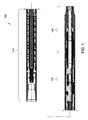
- Figure 1 shows a cross-sectional view of one embodiment of a pulsing tool 100.
- Figures 1A-1C are enlarged partial cross-sectional views of Figure 1 .
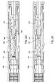
- Figure 2 is a partial cross-sectional view of the pulsing tool 100 of Figure 1 .
- Figures 2A-2C are enlarged partial cross-sectional views of Figure 2 .
- Figures 2D-2E are, respectively, open and close positions of the pulsing tool 100.
- the pulsing tool 100 includes a tubular housing 108 having couplings 121, 122 at the upper and lower ends for connection to other downhole tools. The upper end may be connected to a conveyance string such as coiled tubing, jointed pipe, slickline, and other suitable downhole strings for running a downhole tool.
- the upper end optionally includes an upper catch 120 configured to prevent breakage of the pulsing tool 100.
- the upper catch 120 includes a smaller diameter section 116 disposed between two larger diameter sections 117, 119.
- the smaller diameter section 116 is disposed through an opening 118 of the upper coupling 121.
- the lower end optionally includes a lower catch 125 configured to prevent separation of the pulsing tool 100 in the event the threaded connection of the lower coupling 122 fails.
- the lower catch 125 includes a smaller diameter section 126 disposed between two larger diameter sections 127, 129.
- the smaller diameter section 126 is disposed through an opening 128 of the upper coupling 121.
- the pulsing tool 100 includes a motor unit 110, a pulsing unit 130, and a bearing unit 150.
- the motor unit 110 is a turbine type motor.
- the motor unit 110 includes one or more stages 115 of stationary vanes 111 and rotary vanes 112.
- the motor unit 110 is configured for left hand rotation and has more stationary vanes than rotary vanes.
- the motor shaft 105 of the motor unit 110 has a concentric running motion and provides rotation to the pulsing unit 130.
- the pulsing unit 130 includes a rotating mandrel 131 having one or more inlet openings 132, one or more outlet openings 135, and one or more return openings 137 that fluidly communicate with a bore 143 in the mandrel 131.
- the mandrel 131 is coupled to and rotatable by motor shaft 105 of the motor unit 110.
- An outer annular area between the inlet openings 132 and the outlet openings 135 is closed off by a pulse control bushing 140 to the fluid flow from the motor unit 110 to enter the bore 143 of the rotating mandrel 131 through the inlet openings 132.
- the fluid then exits the bore 143 of the mandrel 131 through the outlet openings 135.
- the pulse control bushing 140 is configured to control the outflow of fluid through the outlet openings 135.
- Figure 1D is a cross-sectional view of the outlet openings 135 and the pulse control bushing 140 disposed in the tubular housing 108.
- three outlet openings 135 are provided in the mandrel 131.
- the pulse control bushing 140 includes at least one fluid flow path. For example, as shown, three recesses 142 circumferentially spaced and aligned with the outlet openings 135. In this position, fluid is allowed to flow out of the mandrel 131 via the outlet openings 135. As the mandrel 131 rotates, for example 60 degrees, the outlet openings 135 may no longer be in alignment with the recesses 142.
- the frequency and the amplitude of the pressure oscillation may be customized for a particular application.
- the number, size, position, and combinations thereof of the outlet openings 135 and recesses 142 may be changed to fit a particular application.
- the number of openings and/or recesses may be modified to change to the frequency.
- the number of openings 135 and the number of recesses 142 may be the same or different.
- the mandrel may have four outlet openings 135 and two recesses 142.
- the relative positions of the openings/recesses may be asymmetrically or symmetrically positioned.
- the size of the openings/recesses may be changed to change amplitude.
- the shape of the openings may have round, slot, or any suitable configuration.
- the frequency may be customized to be different from the frequency of another downhole tool, such as a measure-while-drilling tool, during drilling.
- the pulsing unit 130 may include a pressure relief nozzle 145 positioned in the bore 108 of the mandrel 131 to serve as a constant leak passage.
- the relief nozzle 145 may facilitate the start up of the motor unit 110 by ensuring a passage through the bore 108 for fluid flow.
- the nozzle 145 may be retained by a threaded connection in the mandrel 131, which allows the nozzle 145 to be replaced more easily.
- One or more o-rings may be used to prevent leakage of fluid through the threaded connection.
- the up stream opening of the nozzle 145 is larger than the downstream opening.
- the nozzle 145 is made of tungsten carbide.
- the bore 108 of the mandrel 131 may be narrowed to simulate the function of the nozzle 145.
- the bearing unit 150 is connected below the pulsing unit 130.
- the bearing unit 150 is configured to resist the hydraulic thrust resulting from the fluid pressure oscillation.
- the bearing unit 150 includes a connection sleeve 157 coupled to and rotatable with the rotating mandrel 131.
- a radial bearing 152 and angular contact thrust bearings 154 are used to support the connection sleeve 157 in the tubular housing 108.
- the lower portion of the connection sleeve 157 may be coupled to the lower catch 125.
- Figures 2D-2E show the flow of fluid through the pulsing unit 130 during operation.
- fluid leaving the motor unit 140 flow down the annular area between the mandrel 131 and the tubular housing 108.
- the fluid then enters the bore 143 of the mandrel 131 through the inlet openings 132.
- the fluid exits the bore 143 through the outlet openings 135, when the pulsing unit 130 is in the open position. If the optional relief nozzle 145 is present, some of the fluid may flow through the nozzle 145.
- the exiting fluid flow through the recess 142 of the pulse control bushing 140 and down the annular area between the mandrel 131 and the tubular housing 108 before re-entering the bore 143 through the return openings 137. After re-entering, the fluid continues down the bore 143 to another section of the conveyance string or another component coupled to the conveyance string.
- the pressure is relieved when the outlet openings 135 are aligned with the recesses 142. It is believed that the pressure oscillation in the conveyance string causes the conveyance string to vibrate. As a result, the conveyance string is in constant motion which minimizes the static friction that may be generated when the conveyance string comes into contact with the wellbore.
- a coiled tubing may straighten when the pressure is increased and may flex when the pressure is relieved. This constant motion of the coiled tubing may cause the coiled tubing to skip along the surface of the wellbore, thereby minimizing the effect of static friction on the coiled tubing.
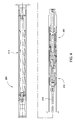
- FIG 3 illustrates an exemplary embodiment of the pulsing tool 100 connected to a drilling tool 160 for a drilling operation.
- the drilling tool 160 includes a positive displacement motor 161 having a drive shaft 162 for connection to a drill bit or other downhole device requiring torque.
- the drilling tool 160 uses a universal joint 163 to transmit torque from the motor 161 to the drive shaft 162.
- the pulsing tool 100 rotates independently from the drilling tool 160.
- FIG 4 illustrate another embodiment of a pulsing tool 200.
- This embodiment 200 is substantially similar to the pulsing tool 100 of Figure 1 , except the motor unit 210 is a positive displacement type motor, also commonly known as "mud motor".
- the pulsing unit 230 and bearing unit 250 will not be described in detail.
- a coupling transmission is used to convert the orbital motion into concentric rotary motion for the pulsing unit 230.
- a flexible shaft 215 is used as a coupling transmission to transmit torque from the motor unit 210 to the pulsing unit 230.
- a universal joint transmission may be used.
- FIG. 5 illustrates an exemplary embodiment of the pulsing tool 200 connected to a drilling tool 160 for a drilling operation.
- the drilling tool 160 includes a positive displacement motor 161 having a drive shaft 162 for connection to a drill bit or other downhole device requiring torque.
- the drilling tool 160 uses a universal joint 163 to transmit torque from the motor 161 to the drive shaft 162.
- the pulsing tool 200 uses a flexible shaft 215 to transmit torque from the motor unit 210 to the pulsing unit 230.
- either or both tools 160, 200 may use a universal joint, flexible shaft, or other suitable transmission devices to transmit torque.
- Figure 6 illustrate another embodiment of a pulsing tool 300.
- Figures 7A-7C are enlarged views of the pulsing tool 300 of Figure 6 .
- the pulsing unit 330 is integrated with the drilling tool.
- the pulsing tool 300 includes a pulsing unit 330 coupled to the motor unit 310 using a connection member such as a universal joint, a flexible joint, and a connection joint.
- the bearing unit 350 is connected downstream from the pulsing unit 330.
- a drive shaft 362 is coupled to the bearing unit 350.
- the motor unit 310 provides the torque for turning the pulsing unit 330 and the drive shaft 362.
- the bearing unit 350 provides axial and radial support to the drive shaft used to drive the drilling bit.
- the openings in the pulsing unit 330 are optionally, round openings instead of slot type openings.
- the round openings are axially spaced to maintain axial integrity of the rotating mandrel.
- the pulsing unit 330 also includes a relief nozzle 345.
- the pulsing unit may be attached to a tubular string equipped with a motor.
- the pulsing unit may be modular unit that can be added or removed from a tubular string as needed.
- the pulsing unit maybe added to a tubular string equipped with a downhole tool such as a drill bit and a motor for driving the downhole tool. After attachment, the motor may be used to drive the pulsing unit as well as the downhole tool.
- the pulsing unit may be arranged upstream or downstream from the motor and/or the downhole tool.
- Embodiments of the pulsing tool may be arranged in a variety of positions relative to a conveyance string and other components on the string.
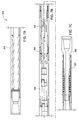
- Figure 8A shows an exemplary embodiment of a drilling assembly having a drill string 410, a pulsing tool 400, and a drill bit or a mill 420 at a lower end.
- Figure 8B shows another embodiment of a drilling assembly having a pulsing tool 400 connected between a first drill string section 411 and a second drill string section 412.
- the drill bit or mill 420 is connected to a lower end of the second drill string section 412.
- Figure 8C shows another embodiment of a drilling assembly having a pulsing tool 400 connected between a first drill string section 411 and a second drill string section 412.
- a motor 430 is connected to a lower end of the second drill string section 412.
- the drill bit or mill 420 is connected to and rotatable by the motor 430.
- Figure 8D shows an exemplary embodiment of a drilling assembly having a drill string 410, a pulsing tool 400, and a motor 430 connected below the pulsing tool 400.
- the motor 430 may be used to rotate a drill bit or a mill 420 at a lower end, and optionally, the pulsing tool 400.
- Figure 8E shows an exemplary embodiment of a drilling assembly having a drill string 410 and a motor 430 connected above the pulsing tool 400.
- the motor 430 may be used to rotate a drill bit or a mill 420 at a lower end as well as the pulsing tool 400.
- Figure 8F shows an exemplary embodiment of a fishing tool assembly having a conveyance string 405, a pulsing tool 400, and an overshot or spear 425 connected to a lower end of the pulsing tool 400.
- the fishing tool may be used to retrieve a stuck object in the wellbore.
- the vibration generated by the pulsing tool 400 may be operated to apply a pulsing, e.g., push and/or pull, force on the object to attempt to free the object.
- Figure 8G shows another embodiment of a fishing tool assembly having a pulsing tool 400 connected between a first conveyance string section 406 and a second conveyance string section 407.
- the overshot or spear 425 is connected to a lower end of the second conveyance string section 407.
- a pulsing tool for use with a tubular string having a motor unit and a pulsing unit coupled to the motor unit.
- the pulsing unit includes a mandrel having an inlet opening and an outlet opening and a flow control bushing, wherein rotation of the mandrel relative to the flow control bushing creates a pressure oscillation which causes movement of the tubular string.
- the flow control bushing includes a fluid flow path selectively aligned with the outlet opening.
- a pressure in the pulsing unit increases in the pulsing unit when the outlet opening is not aligned with the fluid flow path.
- the pressure is relieved with the outlet opening is aligned with the fluid flow path.
- the mandrel further comprises a return opening for returning fluid exiting the outlet opening back into the mandrel.
- the mandrel further comprises a return opening for returning fluid exiting the outlet opening back into the mandrel.
- the mandrel is rotated by the motor unit to the place the outlet opening into or out of alignment with the fluid flow path.
- the pulsing tool includes a tubular housing and an annular area disposed between the tubular housing and the mandrel, wherein the annular area between inlet opening and the outlet opening is blocked from fluid communication.
- the annular area is blocked by the flow control bushing.
- the pulsing tool includes a nozzle disposed in the mandrel and downstream from the inlet opening.
- the pulsing tool includes a catch member configured to prevent separation of the pulsing tool.
- the pulsing unit is coupled to the motor unit using a flexible shaft, a universal joint, a connection joint, and combinations thereof.
- the motor unit is a turbine motor, a positive displacement motor, a mud motor, and combinations thereof.
- the tubular string comprises a coiled tubing.
- the pulsing tool includes a drive shaft coupled to the pulsing unit and rotatable by the motor unit.
- the drive shaft may be used to drive a drill bit.
- a method of moving a tubular string includes coupling the string to a pulsing tool having a motor unit; a pulsing unit having an inlet opening and an outlet opening configured to generate a pressure oscillation in the tubular string; flowing a fluid through the motor unit and then into the pulsing unit via the inlet opening; and periodically allowing the fluid to flow out of the pulsing unit via the outlet opening, thereby generating the pressure oscillation to cause the string to move.
- the pulsing unit includes a flow control bushing having a fluid flow path, whereby the fluid is allowed to periodically flow out of the pulsing unit when the outlet opening is aligned with the fluid flow path.
- a portion of the fluid is allowed to flow through a nozzle disposed in the bore after entering the inlet opening.
- the mandrel is rotated using the motor unit to periodically place the outlet opening in alignment with the fluid flow path.
- the fluid exiting the outlet opening is returned into the mandrel via a return opening.
- a downhole tool is attached to the tubular string and moving the downhole tool with the tubular string.
- the downhole is a fishing tool or a drill bit.
- a pulsing tool for use with a tubular string includes a housing; a rotatable mandrel disposed in the housing, the mandrel having an inlet opening and an outlet opening; and a flow control bushing disposed between the housing and the mandrel, wherein rotation of the mandrel relative to the flow control bushing creates a pressure oscillation which causes movement of the tubular string.
- the flow control bushing includes a fluid flow path.
- rotation of the mandrel places the outlet opening in selective fluid communication with the flow path.
- the mandrel is rotated using a motor unit.
- the pulsing unit may be a modular component that can be connected to a tubular string equipped with a motor, whereby the motor can be used to drive the pulsing unit.
Abstract
Description
- Embodiments of the invention generally relate to a pulsing tool for reducing frictional forces encountered by a conveyance string during operation.
- One of the difficulties coiled tubing "CT" operations encounter is the inability to reach total depth due to high drag forces. The nature of coiled tubing is such that the drill string is not capable of being rotated, so a rotating friction reduction tool is not a viable option. Another limiting factor is that the operations are generally run in very tight or small diameter holes. In some cases, CT operations are performed to refurbish existing wells where mineral buildup and other factors have hindered the flow of oil or gas. The average diameter for a CT is only 2-7/8 inches (29 mm), whereas a standard operation using jointed drill pipe may run pipe ranging from 4 inches (10 cm) to 8 inches (20 cm), in holes of up to 36 inches (91 cm) in diameter. Additionally, if the wellbore has horizontal sections, high frictional drag forces may be generated when the CT is lying on the bottom side of the wellbore.
- There is a need, therefore, for apparatus and methods to reduce the frictional forces encountered by the conveyance string during operation.
- In accordance with one aspect of the present invention there is provided a pulsing tool for use with a tubular string having a motor unit and a pulsing unit coupled to the motor unit. The pulsing unit includes a mandrel having an inlet opening and an outlet opening and a flow control bushing, wherein rotation of the mandrel relative to the flow control bushing creates a pressure oscillation which causes movement of the tubular string.
- In accordance with another aspect of the present invention there is provided a method of moving a tubular string. The method includes coupling the string to a pulsing tool having a motor unit and a pulsing unit having an inlet opening and an outlet opening configured to generate a pressure oscillation in the tubular string. The method further includes flowing a fluid through the motor unit and then into the pulsing unit via the inlet opening, and periodically allowing the fluid to flow out of the pulsing unit via the outlet opening, thereby generating the pressure oscillation to cause the string to move.
- In accordance with another aspect of the present invention there is provided a pulsing tool for use with a tubular string. The pulising tool includes a housing, a rotatable mandrel disposed in the housing, the mandrel having an inlet opening and an outlet opening, and a flow control bushing disposed between the housing and the mandrel. Rotation of the mandrel relative to the flow control bushing creates a pressure oscillation which causes movement of the tubular string.
- In one embodiment, a pulsing tool uses pressure oscillations to reduce friction and help a coiled tubing to "skip" along the wellbore. The pressure oscillations cause the coiled tubing to straighten when pressure is increased and to flex when pressure is decreased. As a result, the coiled tubing is constantly moving during operation. The constant movement of the coiled tubing minimizes the static friction generated when the coiled tubing comes into contact with the wellbore.
- So that the manner in which the above recited features of the present invention can be understood in detail, a more particular description of the invention, briefly summarized above, may be had by reference to embodiments, some of which are illustrated in the appended drawings. It is to be noted, however, that the appended drawings illustrate only typical embodiments of this invention and are therefore not to be considered limiting of its scope, for the invention may admit to other equally effective embodiments.
-
Figure 1 is a cross-sectional view of a pulsing tool. -
Figures 1A-1C show enlarged partial cross-sectional views ofFigure 1 .Figure 1D is a cross-sectional of the pulsing tool ofFigure 1 along lines R1-R1. -
Figure 2 is a cross-sectional view of the pulsing tool ofFigure 1 . -
Figures 2A-2C are enlarged partial cross-sectional views ofFigure 2 .Figures 2D-2E are, respectively, open and close positions of the pulsing tool. -
Figure 3 shows the pulsing tool ofFigure 2 connected to an exemplary drilling tool for a drilling operation. -
Figure 4 illustrates another pulsing tool. -
Figure 5 illustrates the pulsing tool ofFigure 4 connected to an exemplary drilling tool for a drilling operation. -
Figure 6 illustrates another pulsing tool. -
Figures 7A-7C are enlarged views of the pulsing tool ofFigure 6 . -
Figure 8A shows an exemplary embodiment of a drilling assembly. -
Figure 8B shows another embodiment of a drilling assembly. -
Figure 8C shows another embodiment of a drilling assembly. -
Figure 8D shows another embodiment of a drilling assembly. -
Figure 8E shows another embodiment of a drilling assembly. -
Figure 8F shows an exemplary embodiment of a fishing tool assembly. -
Figure 8G shows another embodiment of a fishing tool assembly. - Embodiments of the invention generally relate to a pulsing tool for reducing frictional forces encountered by a conveyance string during operation.
-
Figure 1 shows a cross-sectional view of one embodiment of apulsing tool 100.Figures 1A-1C are enlarged partial cross-sectional views ofFigure 1 .Figure 2 is a partial cross-sectional view of thepulsing tool 100 ofFigure 1 .Figures 2A-2C are enlarged partial cross-sectional views ofFigure 2 .Figures 2D-2E are, respectively, open and close positions of thepulsing tool 100. Thepulsing tool 100 includes atubular housing 108 havingcouplings upper catch 120 configured to prevent breakage of thepulsing tool 100. Theupper catch 120 includes asmaller diameter section 116 disposed between twolarger diameter sections 117, 119. Thesmaller diameter section 116 is disposed through anopening 118 of theupper coupling 121. In the event the threaded connection of theupper coupling 121 fails, theupper catch 120 prevents thepulsing tool 100 from separating. Similarly, the lower end optionally includes alower catch 125 configured to prevent separation of thepulsing tool 100 in the event the threaded connection of thelower coupling 122 fails. Thelower catch 125 includes asmaller diameter section 126 disposed between twolarger diameter sections smaller diameter section 126 is disposed through anopening 128 of theupper coupling 121. - The
pulsing tool 100 includes amotor unit 110, apulsing unit 130, and abearing unit 150. As shown, themotor unit 110 is a turbine type motor. Themotor unit 110 includes one ormore stages 115 ofstationary vanes 111 androtary vanes 112. In one example, themotor unit 110 is configured for left hand rotation and has more stationary vanes than rotary vanes. Themotor shaft 105 of themotor unit 110 has a concentric running motion and provides rotation to thepulsing unit 130. - The
pulsing unit 130 includes a rotatingmandrel 131 having one ormore inlet openings 132, one ormore outlet openings 135, and one ormore return openings 137 that fluidly communicate with abore 143 in themandrel 131. Themandrel 131 is coupled to and rotatable bymotor shaft 105 of themotor unit 110. An outer annular area between theinlet openings 132 and theoutlet openings 135 is closed off by a pulse control bushing 140 to the fluid flow from themotor unit 110 to enter thebore 143 of the rotatingmandrel 131 through theinlet openings 132. The fluid then exits thebore 143 of themandrel 131 through theoutlet openings 135. - The
pulse control bushing 140 is configured to control the outflow of fluid through theoutlet openings 135.Figure 1D is a cross-sectional view of theoutlet openings 135 and the pulse control bushing 140 disposed in thetubular housing 108. As shown, threeoutlet openings 135 are provided in themandrel 131. Thepulse control bushing 140 includes at least one fluid flow path. For example, as shown, threerecesses 142 circumferentially spaced and aligned with theoutlet openings 135. In this position, fluid is allowed to flow out of themandrel 131 via theoutlet openings 135. As themandrel 131 rotates, for example 60 degrees, theoutlet openings 135 may no longer be in alignment with therecesses 142. This position blocks theoutlet openings 135, thereby preventing fluid from flowing out of themandrel 131. Consequently, there is a temporary pressure increase in thepulsing unit 130 when theoutlet openings 135 are blocked. The pressure is relieved when theoutlet openings 135 rotate into alignment with therecesses 142. In this manner, rotation of themandrel 131 causes intermittent increases and decreases to the fluid pressure of the main string. Although not intended to be bound by theory, it is believed the pressure oscillations cause the coiled tubing to vibrate. As a result, the coiled tubing is constantly moving during operation. The constant movement of the coiled tubing minimizes the static friction generated when the coiled tubing comes into contact with the wellbore. The fluid leaving thebushing 140 re-enters themandrel 131 through thereturn openings 137. - In another embodiment, the frequency and the amplitude of the pressure oscillation may be customized for a particular application. The number, size, position, and combinations thereof of the
outlet openings 135 and recesses 142 may be changed to fit a particular application. For example, the number of openings and/or recesses may be modified to change to the frequency. The number ofopenings 135 and the number ofrecesses 142 may be the same or different. For example, the mandrel may have fouroutlet openings 135 and tworecesses 142. In another example, the relative positions of the openings/recesses may be asymmetrically or symmetrically positioned. In yet another example, the size of the openings/recesses may be changed to change amplitude. In one embodiment, the shape of the openings may have round, slot, or any suitable configuration. In one application, the frequency may be customized to be different from the frequency of another downhole tool, such as a measure-while-drilling tool, during drilling. - In another embodiment, the
pulsing unit 130 may include apressure relief nozzle 145 positioned in thebore 108 of themandrel 131 to serve as a constant leak passage. Therelief nozzle 145 may facilitate the start up of themotor unit 110 by ensuring a passage through thebore 108 for fluid flow. In one embodiment, thenozzle 145 may be retained by a threaded connection in themandrel 131, which allows thenozzle 145 to be replaced more easily. One or more o-rings may be used to prevent leakage of fluid through the threaded connection. As shown, the up stream opening of thenozzle 145 is larger than the downstream opening. In one embodiment, thenozzle 145 is made of tungsten carbide. In another embodiment, thebore 108 of themandrel 131 may be narrowed to simulate the function of thenozzle 145. - The
bearing unit 150 is connected below thepulsing unit 130. Thebearing unit 150 is configured to resist the hydraulic thrust resulting from the fluid pressure oscillation. In one embodiment, thebearing unit 150 includes aconnection sleeve 157 coupled to and rotatable with therotating mandrel 131. Aradial bearing 152 and angularcontact thrust bearings 154 are used to support theconnection sleeve 157 in thetubular housing 108. The lower portion of theconnection sleeve 157 may be coupled to thelower catch 125. -
Figures 2D-2E show the flow of fluid through thepulsing unit 130 during operation. In the open position shown inFigure 2D , fluid leaving themotor unit 140 flow down the annular area between themandrel 131 and thetubular housing 108. The fluid then enters thebore 143 of themandrel 131 through theinlet openings 132. The fluid exits thebore 143 through theoutlet openings 135, when thepulsing unit 130 is in the open position. If theoptional relief nozzle 145 is present, some of the fluid may flow through thenozzle 145. The exiting fluid flow through therecess 142 of thepulse control bushing 140 and down the annular area between themandrel 131 and thetubular housing 108 before re-entering thebore 143 through thereturn openings 137. After re-entering, the fluid continues down thebore 143 to another section of the conveyance string or another component coupled to the conveyance string. - In the closed position shown in
Figure 2E , fluid leaving themotor unit 140 flow down the annular area between themandrel 131 and thetubular housing 108. The fluid then enters thebore 143 of themandrel 131 through theinlet openings 132. However, because theoutlet opening 135 is not aligned with therecess 142 of thebushing 140, the fluid is prevented from flowing out of thebore 143 via theoutlet openings 135. Instead, the fluid flows through thenozzle 145 and continue down thebore 143 to another section of the conveyance string or another component coupled to the conveyance string. As discussed above, when theoutlet opening 135 is blocked, a temporary pressure increase is created in thepulsing unit 130. The pressure is relieved when theoutlet openings 135 are aligned with therecesses 142. It is believed that the pressure oscillation in the conveyance string causes the conveyance string to vibrate. As a result, the conveyance string is in constant motion which minimizes the static friction that may be generated when the conveyance string comes into contact with the wellbore. In one example, a coiled tubing may straighten when the pressure is increased and may flex when the pressure is relieved. This constant motion of the coiled tubing may cause the coiled tubing to skip along the surface of the wellbore, thereby minimizing the effect of static friction on the coiled tubing. -
Figure 3 illustrates an exemplary embodiment of thepulsing tool 100 connected to adrilling tool 160 for a drilling operation. Thedrilling tool 160 includes apositive displacement motor 161 having adrive shaft 162 for connection to a drill bit or other downhole device requiring torque. Thedrilling tool 160 uses auniversal joint 163 to transmit torque from themotor 161 to thedrive shaft 162. In this embodiment, thepulsing tool 100 rotates independently from thedrilling tool 160. -
Figure 4 illustrate another embodiment of apulsing tool 200. Thisembodiment 200 is substantially similar to thepulsing tool 100 ofFigure 1 , except themotor unit 210 is a positive displacement type motor, also commonly known as "mud motor". In the interest of clarity, thepulsing unit 230 andbearing unit 250 will not be described in detail. Because thepower unit 210 has an orbital motion, a coupling transmission is used to convert the orbital motion into concentric rotary motion for thepulsing unit 230. As shown, aflexible shaft 215 is used as a coupling transmission to transmit torque from themotor unit 210 to thepulsing unit 230. In another embodiment, a universal joint transmission may be used. -
Figure 5 illustrates an exemplary embodiment of thepulsing tool 200 connected to adrilling tool 160 for a drilling operation. Thedrilling tool 160 includes apositive displacement motor 161 having adrive shaft 162 for connection to a drill bit or other downhole device requiring torque. Thedrilling tool 160 uses auniversal joint 163 to transmit torque from themotor 161 to thedrive shaft 162. In contrast with thedrilling tool 160, thepulsing tool 200 uses aflexible shaft 215 to transmit torque from themotor unit 210 to thepulsing unit 230. However, it is contemplated that either or bothtools -
Figure 6 illustrate another embodiment of apulsing tool 300.Figures 7A-7C are enlarged views of thepulsing tool 300 ofFigure 6 . In this embodiment, thepulsing unit 330 is integrated with the drilling tool. In particular, thepulsing tool 300 includes apulsing unit 330 coupled to themotor unit 310 using a connection member such as a universal joint, a flexible joint, and a connection joint. Thebearing unit 350 is connected downstream from thepulsing unit 330. Adrive shaft 362 is coupled to thebearing unit 350. In this respect, themotor unit 310 provides the torque for turning thepulsing unit 330 and thedrive shaft 362. Thebearing unit 350 provides axial and radial support to the drive shaft used to drive the drilling bit. In this embodiment, the openings in thepulsing unit 330 are optionally, round openings instead of slot type openings. The round openings are axially spaced to maintain axial integrity of the rotating mandrel. Thepulsing unit 330 also includes arelief nozzle 345. - In another embodiment, the pulsing unit may be attached to a tubular string equipped with a motor. For example, the pulsing unit may be modular unit that can be added or removed from a tubular string as needed. In another embodiment, the pulsing unit maybe added to a tubular string equipped with a downhole tool such as a drill bit and a motor for driving the downhole tool. After attachment, the motor may be used to drive the pulsing unit as well as the downhole tool. The pulsing unit may be arranged upstream or downstream from the motor and/or the downhole tool.
- Embodiments of the pulsing tool may be arranged in a variety of positions relative to a conveyance string and other components on the string.
Figure 8A shows an exemplary embodiment of a drilling assembly having adrill string 410, apulsing tool 400, and a drill bit or amill 420 at a lower end. -
Figure 8B shows another embodiment of a drilling assembly having apulsing tool 400 connected between a firstdrill string section 411 and a seconddrill string section 412. The drill bit ormill 420 is connected to a lower end of the seconddrill string section 412. -
Figure 8C shows another embodiment of a drilling assembly having apulsing tool 400 connected between a firstdrill string section 411 and a seconddrill string section 412. Amotor 430 is connected to a lower end of the seconddrill string section 412. The drill bit ormill 420 is connected to and rotatable by themotor 430. -
Figure 8D shows an exemplary embodiment of a drilling assembly having adrill string 410, apulsing tool 400, and amotor 430 connected below thepulsing tool 400. Themotor 430 may be used to rotate a drill bit or amill 420 at a lower end, and optionally, thepulsing tool 400. -
Figure 8E shows an exemplary embodiment of a drilling assembly having adrill string 410 and amotor 430 connected above thepulsing tool 400. Themotor 430 may be used to rotate a drill bit or amill 420 at a lower end as well as thepulsing tool 400. -
Figure 8F shows an exemplary embodiment of a fishing tool assembly having aconveyance string 405, apulsing tool 400, and an overshot orspear 425 connected to a lower end of thepulsing tool 400. In one embodiment, the fishing tool may be used to retrieve a stuck object in the wellbore. The vibration generated by thepulsing tool 400 may be operated to apply a pulsing, e.g., push and/or pull, force on the object to attempt to free the object. -
Figure 8G shows another embodiment of a fishing tool assembly having apulsing tool 400 connected between a firstconveyance string section 406 and a secondconveyance string section 407. The overshot orspear 425 is connected to a lower end of the secondconveyance string section 407. - In accordance with one or mode of the embodiments described herein there is provided a pulsing tool for use with a tubular string having a motor unit and a pulsing unit coupled to the motor unit. In one embodiment, the pulsing unit includes a mandrel having an inlet opening and an outlet opening and a flow control bushing, wherein rotation of the mandrel relative to the flow control bushing creates a pressure oscillation which causes movement of the tubular string.
- In one or more the embodiments described herein, the flow control bushing includes a fluid flow path selectively aligned with the outlet opening.
- In one or more the embodiments described herein, a pressure in the pulsing unit increases in the pulsing unit when the outlet opening is not aligned with the fluid flow path.
- In one or more the embodiments described herein, the pressure is relieved with the outlet opening is aligned with the fluid flow path.
- In one or more the embodiments described herein, the mandrel further comprises a return opening for returning fluid exiting the outlet opening back into the mandrel.
- In one or more the embodiments described herein, the mandrel further comprises a return opening for returning fluid exiting the outlet opening back into the mandrel.
- In one or more the embodiments described herein, the mandrel is rotated by the motor unit to the place the outlet opening into or out of alignment with the fluid flow path.
- In one or more the embodiments described herein, the pulsing tool includes a tubular housing and an annular area disposed between the tubular housing and the mandrel, wherein the annular area between inlet opening and the outlet opening is blocked from fluid communication.
- In one or more the embodiments described herein, the annular area is blocked by the flow control bushing.
- In one or more the embodiments described herein, the pulsing tool includes a nozzle disposed in the mandrel and downstream from the inlet opening.
- In one or more the embodiments described herein, the pulsing tool includes a catch member configured to prevent separation of the pulsing tool.
- In one or more the embodiments described herein, the pulsing unit is coupled to the motor unit using a flexible shaft, a universal joint, a connection joint, and combinations thereof.
- In one or more the embodiments described herein, wherein the motor unit is a turbine motor, a positive displacement motor, a mud motor, and combinations thereof.
- In one or more the embodiments described herein, the tubular string comprises a coiled tubing.
- In one or more the embodiments described herein, the pulsing tool includes a drive shaft coupled to the pulsing unit and rotatable by the motor unit. In another embodiment, the drive shaft may be used to drive a drill bit.
- In another embodiment, a method of moving a tubular string includes coupling the string to a pulsing tool having a motor unit; a pulsing unit having an inlet opening and an outlet opening configured to generate a pressure oscillation in the tubular string; flowing a fluid through the motor unit and then into the pulsing unit via the inlet opening; and periodically allowing the fluid to flow out of the pulsing unit via the outlet opening, thereby generating the pressure oscillation to cause the string to move.
- In one or more the embodiments described herein, the pulsing unit includes a flow control bushing having a fluid flow path, whereby the fluid is allowed to periodically flow out of the pulsing unit when the outlet opening is aligned with the fluid flow path.
- In one or more the embodiments described herein, a portion of the fluid is allowed to flow through a nozzle disposed in the bore after entering the inlet opening.
- In one or more the embodiments described herein, the mandrel is rotated using the motor unit to periodically place the outlet opening in alignment with the fluid flow path.
- In one or more the embodiments described herein, the fluid exiting the outlet opening is returned into the mandrel via a return opening.
- In one or more the embodiments described herein, a downhole tool is attached to the tubular string and moving the downhole tool with the tubular string. In another embodiment, the downhole is a fishing tool or a drill bit.
- In another embodiment, a pulsing tool for use with a tubular string includes a housing; a rotatable mandrel disposed in the housing, the mandrel having an inlet opening and an outlet opening; and a flow control bushing disposed between the housing and the mandrel, wherein rotation of the mandrel relative to the flow control bushing creates a pressure oscillation which causes movement of the tubular string.
- In one or more the embodiments described herein, the flow control bushing includes a fluid flow path.
- In one or more the embodiments described herein, rotation of the mandrel places the outlet opening in selective fluid communication with the flow path.
- In one or more the embodiments described herein, the mandrel is rotated using a motor unit.
- In one or more the embodiments described herein, the pulsing unit may be a modular component that can be connected to a tubular string equipped with a motor, whereby the motor can be used to drive the pulsing unit.
- While the foregoing is directed to embodiments of the present invention, other and further embodiments of the invention may be devised without departing from the basic scope thereof, and the scope thereof is determined by the claims that follow.
Claims (15)
- A pulsing tool for use with a tubular string, comprising:a motor unit;a pulsing unit coupled to the motor unit, the pulsing unit including:a mandrel having an inlet opening and an outlet opening; anda flow control bushing,wherein rotation of the mandrel relative to the flow control bushing creates a pressure oscillation which causes movement of the tubular string.
- The tool of claim 1, wherein the flow control bushing includes a fluid flow path selectively aligned with the outlet opening.
- The tool of claim 2, wherein a pressure in the pulsing unit increases in the pulsing unit when the outlet opening is not aligned with the fluid flow path, and optionally the pressure is relieved when the outlet opening is aligned with the fluid flow path.
- The tool of any preceding claim, wherein the mandrel further comprises a return opening for returning fluid exiting the outlet opening back into the mandrel.
- The tool of any preceding claim, wherein the mandrel is rotated by the motor unit to the place the outlet opening into or out of alignment with the fluid flow path.
- The tool of any preceding claim, further comprising a tubular housing and an annular area disposed between the tubular housing and the mandrel, wherein the annular area between inlet opening and the outlet opening is blocked from fluid communication, the annular area optionally being blocked by the flow control bushing.
- The tool of any preceding claim, further comprising a nozzle disposed in the mandrel and downstream from the inlet opening.
- The tool of any preceding claim, further comprising a catch member configured to prevent separation of the pulsing tool.
- The tool of any preceding claim, wherein the tubular string comprises a coiled tubing.
- A method of moving a tubular string, comprising:coupling the string to a pulsing tool having:a motor unit;a pulsing unit having an inlet opening and an outlet opening configured to generate a pressure oscillation in the tubular string;flowing a fluid through the motor unit and then into the pulsing unit via the inlet opening; andperiodically allowing the fluid to flow out of the pulsing unit via the outlet opening, thereby generating the pressure oscillation to cause the string to move.
- The method of claim 10, wherein the pulsing unit includes a flow control bushing having a fluid flow path, whereby the fluid is allowed to periodically flow out of the pulsing unit when the outlet opening is aligned with the fluid flow path, and optionally the inlet opening and the outlet opening are disposed on a mandrel and in fluid communication with a bore of the mandrel;
- The method of claim 10 or 11, further comprising one or more of the following features:allowing a portion of the fluid to flow through a nozzle disposed in the bore after entering the inlet opening;rotating the mandrel using the motor unit to periodically place the outlet opening in alignment with the fluid flow path; andreturning the fluid exiting the outlet opening into the mandrel via a return opening.
- The method of claim 10, 11 or 12, further comprising attaching a downhole tool to the tubular string and moving the downhole tool with the tubular string, the downhole tool optionally being a fishing tool or drill bit.
- A pulsing tool for use with a tubular string, comprising:a housing;a rotatable mandrel disposed in the housing, the mandrel having an inlet opening and an outlet opening; anda flow control bushing disposed between the housing and the mandrel,wherein rotation of the mandrel relative to the flow control bushing creates a pressure oscillation which causes movement of the tubular string.
- The tool of claim 14, wherein the flow control bushing includes a fluid flow path, rotation of the mandrel optionally placing the outlet opening in selective fluid communication with the flow path; and/or the mandrel is rotated using a motor unit.
Applications Claiming Priority (1)
| Application Number | Priority Date | Filing Date | Title |
|---|---|---|---|
| US201161526639P | 2011-08-23 | 2011-08-23 |
Publications (3)
| Publication Number | Publication Date |
|---|---|
| EP2562350A2 true EP2562350A2 (en) | 2013-02-27 |
| EP2562350A3 EP2562350A3 (en) | 2016-03-30 |
| EP2562350B1 EP2562350B1 (en) | 2017-11-15 |
Family
ID=46750223
Family Applications (1)
| Application Number | Title | Priority Date | Filing Date |
|---|---|---|---|
| EP12181414.9A Active EP2562350B1 (en) | 2011-08-23 | 2012-08-22 | Downhole pulsing tool |
Country Status (6)
| Country | Link |
|---|---|
| US (1) | US9382760B2 (en) |
| EP (1) | EP2562350B1 (en) |
| AR (1) | AR087644A1 (en) |
| CA (1) | CA2787570C (en) |
| DK (1) | DK2562350T3 (en) |
| NO (1) | NO2562350T3 (en) |
Families Citing this family (10)
| Publication number | Priority date | Publication date | Assignee | Title |
|---|---|---|---|---|
| US10465464B2 (en) * | 2014-09-19 | 2019-11-05 | Charles Abernethy Anderson | Apparatus and method for creating tunable pressure pulse |
| WO2017027960A1 (en) * | 2015-08-14 | 2017-02-23 | Impulse Downhole Solutions Ltd. | Lateral drilling method |
| EP3482031B1 (en) | 2016-07-07 | 2021-09-08 | Impulse Downhole Solutions Ltd. | Flow-through pulsing assembly for use in downhole operations |
| US10508496B2 (en) | 2016-12-14 | 2019-12-17 | Directional Vibration Systems Inc. | Downhole vibration tool |
| US10677006B2 (en) * | 2017-11-17 | 2020-06-09 | Rival Downhole Tools Lc | Vibration assembly and method |
| CN107956423B (en) * | 2017-12-19 | 2024-04-05 | 中南大学 | Vortex oscillating jet flow pressure pulse drag reduction tool |
| US10829993B1 (en) | 2019-05-02 | 2020-11-10 | Rival Downhole Tools Lc | Wear resistant vibration assembly and method |
| MX2022010888A (en) | 2020-03-05 | 2022-11-30 | Thru Tubing Solutions Inc | Fluid pulse generation in subterranean wells. |
| US11525307B2 (en) | 2020-03-30 | 2022-12-13 | Thru Tubing Solutions, Inc. | Fluid pulse generation in subterranean wells |
| CA3195403A1 (en) * | 2020-10-26 | 2022-05-05 | Josh CAMPBELL | Improved apparatus and method for creating tunable pressure pulse |
Family Cites Families (15)
| Publication number | Priority date | Publication date | Assignee | Title |
|---|---|---|---|---|
| US2780438A (en) | 1952-05-21 | 1957-02-05 | Exxon Research Engineering Co | Device for drilling wells |
| US3899033A (en) | 1974-01-03 | 1975-08-12 | Huisen Allen T Van | Pneumatic-kinetic drilling system |
| GB8612019D0 (en) * | 1986-05-16 | 1986-06-25 | Shell Int Research | Vibrating pipe string in borehole |
| WO1997044565A1 (en) * | 1996-05-18 | 1997-11-27 | Andergauge Limited | Downhole apparatus |
| GB9708294D0 (en) | 1997-04-24 | 1997-06-18 | Anderson Charles A | Downhole apparatus |
| US6289998B1 (en) * | 1998-01-08 | 2001-09-18 | Baker Hughes Incorporated | Downhole tool including pressure intensifier for drilling wellbores |
| US6073708A (en) * | 1998-07-29 | 2000-06-13 | Dynamo Drilling Services Inc. | Downhole mud pressure intensifier |
| US6626253B2 (en) | 2001-02-27 | 2003-09-30 | Baker Hughes Incorporated | Oscillating shear valve for mud pulse telemetry |
| US6571870B2 (en) * | 2001-03-01 | 2003-06-03 | Schlumberger Technology Corporation | Method and apparatus to vibrate a downhole component |
| US7405998B2 (en) | 2005-06-01 | 2008-07-29 | Halliburton Energy Services, Inc. | Method and apparatus for generating fluid pressure pulses |
| US7617886B2 (en) | 2005-11-21 | 2009-11-17 | Hall David R | Fluid-actuated hammer bit |
| US7708088B2 (en) * | 2008-04-29 | 2010-05-04 | Smith International, Inc. | Vibrating downhole tool |
| US9222312B2 (en) | 2009-06-29 | 2015-12-29 | Ct Energy Ltd. | Vibrating downhole tool |
| US8162078B2 (en) | 2009-06-29 | 2012-04-24 | Ct Energy Ltd. | Vibrating downhole tool |
| CA2680895C (en) | 2009-09-30 | 2017-05-16 | Tartan Controls Inc. | Flow pulsing device for a drilling motor |
-
2012
- 2012-08-21 US US13/590,877 patent/US9382760B2/en active Active
- 2012-08-22 DK DK12181414.9T patent/DK2562350T3/en active
- 2012-08-22 NO NO12181414A patent/NO2562350T3/no unknown
- 2012-08-22 CA CA2787570A patent/CA2787570C/en active Active
- 2012-08-22 EP EP12181414.9A patent/EP2562350B1/en active Active
- 2012-08-23 AR ARP120103102A patent/AR087644A1/en active IP Right Grant
Non-Patent Citations (1)
| Title |
|---|
| None |
Also Published As
| Publication number | Publication date |
|---|---|
| US20130048386A1 (en) | 2013-02-28 |
| NO2562350T3 (en) | 2018-04-14 |
| EP2562350A3 (en) | 2016-03-30 |
| CA2787570C (en) | 2017-02-28 |
| AR087644A1 (en) | 2014-04-09 |
| US9382760B2 (en) | 2016-07-05 |
| CA2787570A1 (en) | 2013-02-23 |
| EP2562350B1 (en) | 2017-11-15 |
| DK2562350T3 (en) | 2018-01-29 |
Similar Documents
| Publication | Publication Date | Title |
|---|---|---|
| EP2562350B1 (en) | Downhole pulsing tool | |
| US20220145714A1 (en) | Friction reduction assembly | |
| US9366100B1 (en) | Hydraulic pipe string vibrator | |
| GB2441214A (en) | A drilling stabilization system | |
| WO2015023904A1 (en) | Axial oscillation device | |
| US10465510B2 (en) | Rotor catch apparatus for downhole motor and method of use | |
| CA3036840C (en) | Downhole tool system and method | |
| US10865612B2 (en) | Downhole pulsation system and method | |
| CA2860873C (en) | Method and apparatus for creating a pressure pulse in drilling fluid to vibrate a drill string | |
| CA2950439C (en) | Powered reaming device | |
| AU2013250913B2 (en) | Wellbore completion system with reaming tool | |
| EP3234299A1 (en) | Borehole conditioning tools | |
| US20210207448A1 (en) | Apparatus for Downhole Milling of Material of a Well Wall | |
| WO2019168896A1 (en) | Drill string applications tool |
Legal Events
| Date | Code | Title | Description |
|---|---|---|---|
| PUAI | Public reference made under article 153(3) epc to a published international application that has entered the european phase |
Free format text: ORIGINAL CODE: 0009012 |
|
| 17P | Request for examination filed |
Effective date: 20120822 |
|
| AK | Designated contracting states |
Kind code of ref document: A2 Designated state(s): AL AT BE BG CH CY CZ DE DK EE ES FI FR GB GR HR HU IE IS IT LI LT LU LV MC MK MT NL NO PL PT RO RS SE SI SK SM TR |
|
| AX | Request for extension of the european patent |
Extension state: BA ME |
|
| RAP1 | Party data changed (applicant data changed or rights of an application transferred) |
Owner name: WEATHERFORD/LAMB, INC. |
|
| RAP1 | Party data changed (applicant data changed or rights of an application transferred) |
Owner name: WEATHERFORD TECHNOLOGY HOLDINGS, LLC |
|
| PUAL | Search report despatched |
Free format text: ORIGINAL CODE: 0009013 |
|
| AK | Designated contracting states |
Kind code of ref document: A3 Designated state(s): AL AT BE BG CH CY CZ DE DK EE ES FI FR GB GR HR HU IE IS IT LI LT LU LV MC MK MT NL NO PL PT RO RS SE SI SK SM TR |
|
| AX | Request for extension of the european patent |
Extension state: BA ME |
|
| RIC1 | Information provided on ipc code assigned before grant |
Ipc: E21B 28/00 20060101ALI20160225BHEP Ipc: E21B 23/14 20060101AFI20160225BHEP |
|
| STAA | Information on the status of an ep patent application or granted ep patent |
Free format text: STATUS: EXAMINATION IS IN PROGRESS |
|
| 17Q | First examination report despatched |
Effective date: 20170322 |
|
| GRAP | Despatch of communication of intention to grant a patent |
Free format text: ORIGINAL CODE: EPIDOSNIGR1 |
|
| STAA | Information on the status of an ep patent application or granted ep patent |
Free format text: STATUS: GRANT OF PATENT IS INTENDED |
|
| INTG | Intention to grant announced |
Effective date: 20170721 |
|
| GRAS | Grant fee paid |
Free format text: ORIGINAL CODE: EPIDOSNIGR3 |
|
| GRAA | (expected) grant |
Free format text: ORIGINAL CODE: 0009210 |
|
| STAA | Information on the status of an ep patent application or granted ep patent |
Free format text: STATUS: THE PATENT HAS BEEN GRANTED |
|
| AK | Designated contracting states |
Kind code of ref document: B1 Designated state(s): AL AT BE BG CH CY CZ DE DK EE ES FI FR GB GR HR HU IE IS IT LI LT LU LV MC MK MT NL NO PL PT RO RS SE SI SK SM TR |
|
| REG | Reference to a national code |
Ref country code: CH Ref legal event code: EP Ref country code: GB Ref legal event code: FG4D Ref country code: AT Ref legal event code: REF Ref document number: 946479 Country of ref document: AT Kind code of ref document: T Effective date: 20171115 |
|
| REG | Reference to a national code |
Ref country code: IE Ref legal event code: FG4D |
|
| REG | Reference to a national code |
Ref country code: DE Ref legal event code: R096 Ref document number: 602012039714 Country of ref document: DE |
|
| REG | Reference to a national code |
Ref country code: DK Ref legal event code: T3 Effective date: 20180126 |
|
| REG | Reference to a national code |
Ref country code: RO Ref legal event code: EPE |
|
| REG | Reference to a national code |
Ref country code: NL Ref legal event code: FP |
|
| REG | Reference to a national code |
Ref country code: LT Ref legal event code: MG4D |
|
| REG | Reference to a national code |
Ref country code: AT Ref legal event code: MK05 Ref document number: 946479 Country of ref document: AT Kind code of ref document: T Effective date: 20171115 |
|
| REG | Reference to a national code |
Ref country code: NO Ref legal event code: T2 Effective date: 20171115 |
|
| PG25 | Lapsed in a contracting state [announced via postgrant information from national office to epo] |
Ref country code: SE Free format text: LAPSE BECAUSE OF FAILURE TO SUBMIT A TRANSLATION OF THE DESCRIPTION OR TO PAY THE FEE WITHIN THE PRESCRIBED TIME-LIMIT Effective date: 20171115 Ref country code: LT Free format text: LAPSE BECAUSE OF FAILURE TO SUBMIT A TRANSLATION OF THE DESCRIPTION OR TO PAY THE FEE WITHIN THE PRESCRIBED TIME-LIMIT Effective date: 20171115 Ref country code: FI Free format text: LAPSE BECAUSE OF FAILURE TO SUBMIT A TRANSLATION OF THE DESCRIPTION OR TO PAY THE FEE WITHIN THE PRESCRIBED TIME-LIMIT Effective date: 20171115 Ref country code: ES Free format text: LAPSE BECAUSE OF FAILURE TO SUBMIT A TRANSLATION OF THE DESCRIPTION OR TO PAY THE FEE WITHIN THE PRESCRIBED TIME-LIMIT Effective date: 20171115 |
|
| PG25 | Lapsed in a contracting state [announced via postgrant information from national office to epo] |
Ref country code: RS Free format text: LAPSE BECAUSE OF FAILURE TO SUBMIT A TRANSLATION OF THE DESCRIPTION OR TO PAY THE FEE WITHIN THE PRESCRIBED TIME-LIMIT Effective date: 20171115 Ref country code: LV Free format text: LAPSE BECAUSE OF FAILURE TO SUBMIT A TRANSLATION OF THE DESCRIPTION OR TO PAY THE FEE WITHIN THE PRESCRIBED TIME-LIMIT Effective date: 20171115 Ref country code: HR Free format text: LAPSE BECAUSE OF FAILURE TO SUBMIT A TRANSLATION OF THE DESCRIPTION OR TO PAY THE FEE WITHIN THE PRESCRIBED TIME-LIMIT Effective date: 20171115 Ref country code: GR Free format text: LAPSE BECAUSE OF FAILURE TO SUBMIT A TRANSLATION OF THE DESCRIPTION OR TO PAY THE FEE WITHIN THE PRESCRIBED TIME-LIMIT Effective date: 20180216 Ref country code: AT Free format text: LAPSE BECAUSE OF FAILURE TO SUBMIT A TRANSLATION OF THE DESCRIPTION OR TO PAY THE FEE WITHIN THE PRESCRIBED TIME-LIMIT Effective date: 20171115 Ref country code: BG Free format text: LAPSE BECAUSE OF FAILURE TO SUBMIT A TRANSLATION OF THE DESCRIPTION OR TO PAY THE FEE WITHIN THE PRESCRIBED TIME-LIMIT Effective date: 20180215 |
|
| REG | Reference to a national code |
Ref country code: FR Ref legal event code: PLFP Year of fee payment: 7 |
|
| PG25 | Lapsed in a contracting state [announced via postgrant information from national office to epo] |
Ref country code: CY Free format text: LAPSE BECAUSE OF FAILURE TO SUBMIT A TRANSLATION OF THE DESCRIPTION OR TO PAY THE FEE WITHIN THE PRESCRIBED TIME-LIMIT Effective date: 20171115 Ref country code: EE Free format text: LAPSE BECAUSE OF FAILURE TO SUBMIT A TRANSLATION OF THE DESCRIPTION OR TO PAY THE FEE WITHIN THE PRESCRIBED TIME-LIMIT Effective date: 20171115 Ref country code: SK Free format text: LAPSE BECAUSE OF FAILURE TO SUBMIT A TRANSLATION OF THE DESCRIPTION OR TO PAY THE FEE WITHIN THE PRESCRIBED TIME-LIMIT Effective date: 20171115 Ref country code: CZ Free format text: LAPSE BECAUSE OF FAILURE TO SUBMIT A TRANSLATION OF THE DESCRIPTION OR TO PAY THE FEE WITHIN THE PRESCRIBED TIME-LIMIT Effective date: 20171115 |
|
| REG | Reference to a national code |
Ref country code: DE Ref legal event code: R097 Ref document number: 602012039714 Country of ref document: DE |
|
| PG25 | Lapsed in a contracting state [announced via postgrant information from national office to epo] |
Ref country code: PL Free format text: LAPSE BECAUSE OF FAILURE TO SUBMIT A TRANSLATION OF THE DESCRIPTION OR TO PAY THE FEE WITHIN THE PRESCRIBED TIME-LIMIT Effective date: 20171115 Ref country code: IT Free format text: LAPSE BECAUSE OF FAILURE TO SUBMIT A TRANSLATION OF THE DESCRIPTION OR TO PAY THE FEE WITHIN THE PRESCRIBED TIME-LIMIT Effective date: 20171115 Ref country code: SM Free format text: LAPSE BECAUSE OF FAILURE TO SUBMIT A TRANSLATION OF THE DESCRIPTION OR TO PAY THE FEE WITHIN THE PRESCRIBED TIME-LIMIT Effective date: 20171115 |
|
| PLBE | No opposition filed within time limit |
Free format text: ORIGINAL CODE: 0009261 |
|
| STAA | Information on the status of an ep patent application or granted ep patent |
Free format text: STATUS: NO OPPOSITION FILED WITHIN TIME LIMIT |
|
| 26N | No opposition filed |
Effective date: 20180817 |
|
| PG25 | Lapsed in a contracting state [announced via postgrant information from national office to epo] |
Ref country code: SI Free format text: LAPSE BECAUSE OF FAILURE TO SUBMIT A TRANSLATION OF THE DESCRIPTION OR TO PAY THE FEE WITHIN THE PRESCRIBED TIME-LIMIT Effective date: 20171115 |
|
| PG25 | Lapsed in a contracting state [announced via postgrant information from national office to epo] |
Ref country code: MC Free format text: LAPSE BECAUSE OF FAILURE TO SUBMIT A TRANSLATION OF THE DESCRIPTION OR TO PAY THE FEE WITHIN THE PRESCRIBED TIME-LIMIT Effective date: 20171115 |
|
| REG | Reference to a national code |
Ref country code: CH Ref legal event code: PL |
|
| PG25 | Lapsed in a contracting state [announced via postgrant information from national office to epo] |
Ref country code: LI Free format text: LAPSE BECAUSE OF NON-PAYMENT OF DUE FEES Effective date: 20180831 Ref country code: LU Free format text: LAPSE BECAUSE OF NON-PAYMENT OF DUE FEES Effective date: 20180822 Ref country code: CH Free format text: LAPSE BECAUSE OF NON-PAYMENT OF DUE FEES Effective date: 20180831 |
|
| REG | Reference to a national code |
Ref country code: BE Ref legal event code: MM Effective date: 20180831 |
|
| PG25 | Lapsed in a contracting state [announced via postgrant information from national office to epo] |
Ref country code: BE Free format text: LAPSE BECAUSE OF NON-PAYMENT OF DUE FEES Effective date: 20180831 |
|
| PG25 | Lapsed in a contracting state [announced via postgrant information from national office to epo] |
Ref country code: MT Free format text: LAPSE BECAUSE OF NON-PAYMENT OF DUE FEES Effective date: 20180822 |
|
| PG25 | Lapsed in a contracting state [announced via postgrant information from national office to epo] |
Ref country code: TR Free format text: LAPSE BECAUSE OF FAILURE TO SUBMIT A TRANSLATION OF THE DESCRIPTION OR TO PAY THE FEE WITHIN THE PRESCRIBED TIME-LIMIT Effective date: 20171115 |
|
| PG25 | Lapsed in a contracting state [announced via postgrant information from national office to epo] |
Ref country code: HU Free format text: LAPSE BECAUSE OF FAILURE TO SUBMIT A TRANSLATION OF THE DESCRIPTION OR TO PAY THE FEE WITHIN THE PRESCRIBED TIME-LIMIT; INVALID AB INITIO Effective date: 20120822 Ref country code: PT Free format text: LAPSE BECAUSE OF FAILURE TO SUBMIT A TRANSLATION OF THE DESCRIPTION OR TO PAY THE FEE WITHIN THE PRESCRIBED TIME-LIMIT Effective date: 20171115 |
|
| PG25 | Lapsed in a contracting state [announced via postgrant information from national office to epo] |
Ref country code: IE Free format text: LAPSE BECAUSE OF NON-PAYMENT OF DUE FEES Effective date: 20180822 Ref country code: MK Free format text: LAPSE BECAUSE OF NON-PAYMENT OF DUE FEES Effective date: 20171115 |
|
| PG25 | Lapsed in a contracting state [announced via postgrant information from national office to epo] |
Ref country code: AL Free format text: LAPSE BECAUSE OF FAILURE TO SUBMIT A TRANSLATION OF THE DESCRIPTION OR TO PAY THE FEE WITHIN THE PRESCRIBED TIME-LIMIT Effective date: 20171115 Ref country code: IS Free format text: LAPSE BECAUSE OF FAILURE TO SUBMIT A TRANSLATION OF THE DESCRIPTION OR TO PAY THE FEE WITHIN THE PRESCRIBED TIME-LIMIT Effective date: 20180315 |
|
| REG | Reference to a national code |
Ref country code: NL Ref legal event code: RC Free format text: DETAILS LICENCE OR PLEDGE: RIGHT OF PLEDGE, ESTABLISHED Name of requester: DEUTSCHE BANK TRUST COMPANY AMERICAS Effective date: 20200723 |
|
| REG | Reference to a national code |
Ref country code: GB Ref legal event code: 732E Free format text: REGISTERED BETWEEN 20200813 AND 20200819 |
|
| PGFP | Annual fee paid to national office [announced via postgrant information from national office to epo] |
Ref country code: NL Payment date: 20200814 Year of fee payment: 9 |
|
| PGFP | Annual fee paid to national office [announced via postgrant information from national office to epo] |
Ref country code: FR Payment date: 20200715 Year of fee payment: 9 Ref country code: DE Payment date: 20200812 Year of fee payment: 9 Ref country code: DK Payment date: 20200811 Year of fee payment: 9 |
|
| REG | Reference to a national code |
Ref country code: GB Ref legal event code: 732E Free format text: REGISTERED BETWEEN 20201126 AND 20201202 |
|
| REG | Reference to a national code |
Ref country code: GB Ref legal event code: 732E Free format text: REGISTERED BETWEEN 20210225 AND 20210303 |
|
| REG | Reference to a national code |
Ref country code: DE Ref legal event code: R119 Ref document number: 602012039714 Country of ref document: DE |
|
| REG | Reference to a national code |
Ref country code: DK Ref legal event code: EBP Effective date: 20210831 |
|
| REG | Reference to a national code |
Ref country code: NL Ref legal event code: MM Effective date: 20210901 |
|
| PG25 | Lapsed in a contracting state [announced via postgrant information from national office to epo] |
Ref country code: NL Free format text: LAPSE BECAUSE OF NON-PAYMENT OF DUE FEES Effective date: 20210901 |
|
| PG25 | Lapsed in a contracting state [announced via postgrant information from national office to epo] |
Ref country code: FR Free format text: LAPSE BECAUSE OF NON-PAYMENT OF DUE FEES Effective date: 20210831 Ref country code: DK Free format text: LAPSE BECAUSE OF NON-PAYMENT OF DUE FEES Effective date: 20210831 Ref country code: DE Free format text: LAPSE BECAUSE OF NON-PAYMENT OF DUE FEES Effective date: 20220301 |
|
| PGFP | Annual fee paid to national office [announced via postgrant information from national office to epo] |
Ref country code: RO Payment date: 20220727 Year of fee payment: 11 |
|
| PGFP | Annual fee paid to national office [announced via postgrant information from national office to epo] |
Ref country code: NO Payment date: 20230809 Year of fee payment: 12 Ref country code: GB Payment date: 20230629 Year of fee payment: 12 |
|
| P01 | Opt-out of the competence of the unified patent court (upc) registered |
Effective date: 20230922 |
|
| PG25 | Lapsed in a contracting state [announced via postgrant information from national office to epo] |
Ref country code: RO Free format text: LAPSE BECAUSE OF NON-PAYMENT OF DUE FEES Effective date: 20230822 |