EP2562345A2 - Blind having cord shrouds - Google Patents
Blind having cord shrouds Download PDFInfo
- Publication number
- EP2562345A2 EP2562345A2 EP12005966A EP12005966A EP2562345A2 EP 2562345 A2 EP2562345 A2 EP 2562345A2 EP 12005966 A EP12005966 A EP 12005966A EP 12005966 A EP12005966 A EP 12005966A EP 2562345 A2 EP2562345 A2 EP 2562345A2
- Authority
- EP
- European Patent Office
- Prior art keywords
- cord
- ladders
- blind
- shroud
- shrouds
- Prior art date
- Legal status (The legal status is an assumption and is not a legal conclusion. Google has not performed a legal analysis and makes no representation as to the accuracy of the status listed.)
- Withdrawn
Links
Images

Classifications
-
- E—FIXED CONSTRUCTIONS
- E06—DOORS, WINDOWS, SHUTTERS, OR ROLLER BLINDS IN GENERAL; LADDERS
- E06B—FIXED OR MOVABLE CLOSURES FOR OPENINGS IN BUILDINGS, VEHICLES, FENCES OR LIKE ENCLOSURES IN GENERAL, e.g. DOORS, WINDOWS, BLINDS, GATES
- E06B9/00—Screening or protective devices for wall or similar openings, with or without operating or securing mechanisms; Closures of similar construction
- E06B9/24—Screens or other constructions affording protection against light, especially against sunshine; Similar screens for privacy or appearance; Slat blinds
- E06B9/26—Lamellar or like blinds, e.g. venetian blinds
- E06B9/28—Lamellar or like blinds, e.g. venetian blinds with horizontal lamellae, e.g. non-liftable
- E06B9/30—Lamellar or like blinds, e.g. venetian blinds with horizontal lamellae, e.g. non-liftable liftable
- E06B9/32—Operating, guiding, or securing devices therefor
- E06B9/326—Details of cords, e.g. buckles, drawing knobs
Definitions
- the present invention relates to window coverings, such as blinds, venetian blinds, or other types of blinds.
- the CPSC has issued guidelines, rules and proposed rules that require window covering manufacturers to make shades with inaccessible cords or to construct the window covering product in a manner so that a child cannot form a loop in a cord which is large enough, greater than 20.32 cm (8 inches) in diameter, for a child's head to fit through the loop.
- 5,495,883 and 5,613,540 discloses cord shrouds used on the front of a blind.
- Child safety devices may be configured to keep the lift cords taught so that the cords cannot be pulled away from the window covering material and form a noose or release the cord from the shade when a child becomes entangled in the shade.
- a new window covering is needed to replace or change conventional blind designs to help prevent the entanglement of children within exposed cords.
- such a design prevents loops from being formed such that children cannot become entangled with lift cords while also covering or enclosing lift cords of the blind.
- a blind may include a headrail, a plurality of ladders extending from the headrail, a plurality of slats supported on the ladders, a plurality of lift cords extending from the headrail, and a plurality of cord shrouds.
- the ladders may each comprise a column of rungs extending between two spaced apart rails.
- the slats may include a lowermost slat that is positioned furthest from the headrail.
- Each lift cord is adjacent to one of the ladders and extends to the lowermost slat.
- Each of the cord shrouds encloses a portion of one of the lift cords that extends from the headrail to a position adjacent to the lowermost slat and is also attached to the ladder that is adjacent the lift cord enclosed by the cord shroud.
- the slats of the blind may be composed of any of a number of suitable materials.
- slats may be composed of metal or plastic.
- Each of the cord shrouds may be attached to a respective one of the ladders at spaced apart positions. Each cord shroud may be attached to one of the rails of the ladder to which it is attached or may be attached to both rails. Each cord shroud could alternatively be attached to one or more rungs of the ladder to which it is attached or be attached to all the rungs of the ladder. In yet other alternatives, each cord shroud could be attached to one or more of the rails and also be attached to one or more of the rungs of the ladder to which it is attached.
- a plurality of fasteners may be used to attach the cord shrouds to at least one of the rails of the ladder, one or more of the rungs of the ladder, or both the rails and rungs of the ladder to which the cord shroud is attached.
- the fasteners may be loops, rings, adjustable loops, zip ties, other fasteners, or fastening mechanisms such as sewn connections or other types of formed connections.
- the lift cords and cord shrouds may extend through the slats. In other embodiments, the lift cords and shrouds may extend adjacent to an edge of each of the slats without passing through the slats.
- Embodiments of the blind may include a bottom rail, which may be below the lowermost slat. The portion of each of the lift cords may extend to that bottom rail. Additionally, each cord shroud may extend to the bottom rail.
- the cord shrouds may be attached to the headrail at one end and have an opposite end attached to the lowermost slat or bottom rail.
- a first end of each cord shroud may be attached to the headrail and a second end opposite the first end may be attached to the bottom rail or lowermost slat.
- the first end of each cord shroud may be an upper end and the second end of each cord shroud may be a lower end.
- a blind may include a first rail, a plurality of ladders extending from the first rail, a plurality of slats, and a plurality of lift cords extending from the first rail.
- Each lift cord may be adjacent to one of the plurality of ladders and extend to the lowermost slat of the slats.
- Each of the ladders may be comprised of at least one cord shroud and a column of rungs attached to the at least one cord shroud. The rungs support the slats.
- the at least one cord shroud encloses a portion of one of the lift cords that extends from the first rail to a position adjacent to the lowermost slat.
- the ladder may be comprised of only one cord shroud and is further comprised of an elongated flexible member that extends from the first rail to a position adjacent to the lowermost slat.
- the rungs of the ladder may extend between the flexible elongated member and the cord shroud to support the slats.
- the at least one cord shroud is attached to the flexible elongated member by the rungs such that the portion of the lift cord enclosed by the cord shroud is prevented from being pulled away from the slats to form a loop having a diameter of greater than 15.24 cm (six inches).
- Embodiments of the blind may also include a lift cord control mechanism, such as a cord lock, spring motor, or motor that is configured to control movement of the lift cords for lowering and raising the blind.
- the lift cord control mechanism may be attached to the lift cords so that actuation of the mechanism permits or causes movement of the lift cords for raising and lowering of the blind.
- a tilt mechanism may be attached o the ladders so that the slats may be moved from an open position to a closed position.
- a separate actuation mechanism may be attached to the tilt mechanism for tilting of the slats.
- a blind 1 may include a headrail 2, a bottom rail 3, and window covering material 5 that extends between the headrail 2 and the bottom rail 3.
- the window covering material 5 may include slats 4 that are positioned on rungs of a plurality of ladders 6.
- the slats may be composed of metal, such as aluminum, or may be composed of plastic.
- a cord lock 19 or other lift cord control mechanism may be attached to the headrail to control movement of lift cords that extend from the headrail 2 to the bottom rail 3.
- the lift cords may pass through the window covering material 5 by passing through holes in the slats 4 or may pass alongside the window covering material 5 by passing alongside an edge of each slat. It should be understood that alternative embodiments of the blind that do not utilize a bottom rail may have the lift cords extend to the lowermost slat of the window covering material.
- the lift cords may be wound and unwound from a shaft in the headrail or be wound and unwound from one or more spools positioned in the headrail. Winding of the lift cords raises the blind, or retracts the window covering material. Unwinding of the lift cords extends the window covering material, or lowers the blind.
- Lift cords may be lifting tape, cord material, elongated straps having a width of between 2.54 and 7.62 cm (between 1 and three inches), or may be other flexible elongated members.
- the ladders 6 may include a first ladder and a second ladder.
- the first ladder may have first rails 7 and rungs 10 that extend between the pair of first rails 7.
- the first rails 7 may include a front rail positioned on the front face of the window covering material and a rear rail positioned on the rear face of the window covering material.
- the second ladder may have second rails 9 and rungs that extend between the pair of second rails 9.
- One second rail may be positioned on the front face of the window covering material and the other second rail may be on the rear face of the window covering material.
- the rungs of the ladders support the slats 4.
- the ladders may be attached to a tilt mechanism located in or attached to the headrail that is actuated by a tilt rod or other actuation device so that the ladders may be moved to tilt the slats 4 from a closed position, as shown in Figure 1 to an open position, as shown in Figure 2 .
- the rails 7, 9 of the ladders may be cords, tape, or portions of cord material.
- the rails could also be comprised of other types of flexible elongated members.
- the rungs of each ladder may be portions of a cord, one or more strands of cord, segments of tape, or other material which is known in the art.
- each lift cord that extends out of the headrail 2 and to the bottom rail 3 is enclosed by a cord shroud.
- a first lift cord 11 is enclosed by a first cord shroud 13 and a second lift cord 12 is enclosed by a second cord shroud 15.
- the cord shrouds may be series of webs extending between spaced apart rungs to define a generally tubular structure.
- each cord shroud may be a tubular cloth structure or tubular structure having a mesh surface.
- the cord shrouds may be spiral structures defining an aperture through which a portion of a lift cord passes.
- the cord shrouds may be composed of a cloth material, mesh material, or interwoven filaments.
- the cord shrouds may fully enclose the portion of the lift cord or, alternatively, may substantially enclose a lift cord.
- Each of the cord shrouds may have a top end attached to the headrail 2 and a bottom end attached to the bottom rail 3. In embodiments that do not have a bottom rail 3, the bottom end of the cord shroud may be attached to the lowermost slat.
- the cord shrouds are also attached to the ladders of the blind 1.
- the cord shrouds for each lift cord may be attached to the ladder adjacent to that lift cord.
- the cord shroud may be attached to the ladder at spaced apart locations by loops, adjustable loops, adjustable zip ties, zip ties, rings, sewn connections, sewn connectors, or other fasteners or fastening mechanisms.
- Each cord shroud may be attached to the one or both rails of a ladder, to one or more rungs of the ladder, or to all the rungs of the ladder.
- a cord shroud could also be attached to at least one rail of the ladder and at least some of the rungs of the ladder as well.
- each cord shroud may be attached to a rail of the respective ladder to which the cord shroud is adjacent.
- the first cord shroud 13 that encloses a portion of the first lift cord 11 that extends from the headrail 2 to the bottom rail 3 may be attached to a rail 7 of the ladder adjacent to that cord shroud.
- Loops 21 may extend from the first cord shroud 13 to the rail 7.
- the loops 21 may be spaced apart by a predetermined distance to provide a number of different locations of attachment to the rail 7.
- the loops 21 may each be 10.16 cm, 12.7 cm, or 15.24 cm (4 inches, 5 inches, or 6 inches) away from a loop that is immediately below or above that loop.
- the loops 21 may be positioned to attach the cord shroud to a junction of a rung and a rail on a periodic basis, such as having such a connection formed on the rail at every other rung.
- the attachment locations are positioned to prevent the cord shroud from being pulled away from the slats 4 to form a loop of over 15.24 cm (six inches) in diameter or over 20.32 cm (eight inches) in diameter.
- the cord shrouds and lift cords may pass through each of the slats by passing through holes 17 in the slats.
- the cord shrouds and lift cords may pass adjacent to an edge of the slats or along an edge of the slats, as may be appreciated from Figure 5 .
- loops 23 may extend from the cord shroud to rungs 10 of the ladder adjacent that cord shroud.
- loops or rings 24 may extend from the cord shroud to attach the cord shroud to a rail of the ladder at different locations. As discussed above, the locations at which the cord shroud is attached to the ladder are spaced apart to prevent the formation of a loop that may pose an entanglement danger to small children.
- the cord shroud 13 and lift cord 11 may pass through holes in the slats and also pass through gaps 10a formed between rungs of the ladder adjacent the cord shroud.
- multiple rungs may extend between a pair of rails to support a portion of a slat 4.
- a gap 10a may be defined between these rungs.
- the lift cord and cord shroud may extend through a hole in the slat and also pass through the gap 10a.
- ladders 30 of the blind may have rails that also function as cord shrouds.
- an embodiment of the blind may include slats 4 that are supported on rungs 10.
- the rungs 10 may extend between two rails.
- the rails may be tubular structures that have mesh surfaces that are capable of functioning as cord shrouds.
- a lift cord 31 may pass through one of the rails that functions as and is a cord shroud 32.
- a second lift cord (not shown) may pass through the opposite rail that functions as a cord shroud as well.
- the cord shroud 32 may enclose a portion of the lift cord 31 that extends out of the headrail of a blind and to a bottom rail or lowermost slat while also being periodically attached to the ladder via the rungs 10 attached to the opposite rail. Such periodic attachment of the cord shroud to the opposite rail by the rungs can prevent the pulling away of the enclosed portion of the lift cord to form a dangerous loop.
- the ladders may include rails defined by cords 37 that pass through the cord shrouds 32 to form rails of the ladder that are attached to the rungs 10.
- the cord shrouds may cover a portion of respective ones of the lift cords 31 and also cover a portion of the rails 37.
- another alternative embodiment of my blind may include a ladder that only uses one cord shroud 32 that may either also function as a rail or, alternatively, may be positioned so that the cord shroud 32 covers both a lift cord 31 and a cord 37 that functions as a rail for a ladder.
- the rail opposite the cord shroud 32 may only be a cord 37.
- the cord shroud 32 may function as a rail of the ladder and be periodically attached to the rail 37 via the rungs 10 to prevent the lift cord enclosed by the cord shroud 32 from being pulled away form the slats to form a loop that may be dangerous to a small child.
- Such an embodiment may be configured so that after the blind is mounted adjacent to a window, the cord shrouds are positioned adjacent the window on a rear side of the blind to hide the cord shrouds from view from a person in a room.
- the blind may then appear to the user in the room as a typical venetian blind while also providing the protection afforded by the cord shroud covering the lift cord and preventing the substantial pulling of lift cords away from the slats 4 that have the potential for leading to an occurrence of a dangerous child entanglement with such a pulled lift cord.
- a blind may have any number of lift cords, ladders for supporting the slats, and cord shrouds.
- the number of lift cords, ladders, and cord shrouds used may depend on a number of design and aesthetic options, such as the size of the blind and the length and weight of the slats.
- lift cord control mechanisms may be utilized instead of a cord lock in other embodiments of the blind.
- lift cord control mechanisms such as spring motor arrangements used in cordless shades, motors, or other lift cord control systems may be utilized in some embodiments of the blind.
Abstract
Description
- The present invention relates to window coverings, such as blinds, venetian blinds, or other types of blinds.
- On occasion, children have been able to get behind a lowered Roman shade, pull a lift cord to form a loop and become entangled in the loop. If the lift cord is around the child's neck and the child falls, the cord could act as a noose and strangle the child. Children have also become entangled within lift cords of venetian blinds. Reports of such incidents have prompted at least one major retailer to issue a recall of one product line of Roman shades and the United States Consumer Product Safety Commission (CPSC) has issued a warning about the danger of child entanglement with cords of window coverings. In addition the CPSC has issued guidelines, rules and proposed rules that require window covering manufacturers to make shades with inaccessible cords or to construct the window covering product in a manner so that a child cannot form a loop in a cord which is large enough, greater than 20.32 cm (8 inches) in diameter, for a child's head to fit through the loop.
- The art has developed various types of child safety devices that are intended to prevent deaths of children who become entangled in lift cords. For instance,
U.S. Patent Nos. 7,318,251 ,7,261,138 ,7,225,850 ,7,117,918 ,7,086,446 ,7,000,672 ,6,948,546 ,6,918,425 ,6,860,312 ,6,637,493 ,6,484,787 ,6,431,248 ,5,630,458 ,5,533,559 and4,909,298 andU.S. Patent Application Publication Nos. 2008/0110581 ,2007/0023149 and2006/0144526 disclose child safety devices for blinds.U.S. Patent Nos. 5,495,883 and5,613,540 discloses cord shrouds used on the front of a blind. Child safety devices may be configured to keep the lift cords taught so that the cords cannot be pulled away from the window covering material and form a noose or release the cord from the shade when a child becomes entangled in the shade. - Other examples of child safety devices may be appreciated from my
U.S. Patent Application No. 13/185,629 , which was filed on July 19, 2011. This application discloses shrouds that may be used in connection with window coverings such as Roman shades, pleated shades, Venetian blinds, and other window coverings with cords. - A new window covering is needed to replace or change conventional blind designs to help prevent the entanglement of children within exposed cords. Preferably, such a design prevents loops from being formed such that children cannot become entangled with lift cords while also covering or enclosing lift cords of the blind.
- A blind may include a headrail, a plurality of ladders extending from the headrail, a plurality of slats supported on the ladders, a plurality of lift cords extending from the headrail, and a plurality of cord shrouds. The ladders may each comprise a column of rungs extending between two spaced apart rails. The slats may include a lowermost slat that is positioned furthest from the headrail. Each lift cord is adjacent to one of the ladders and extends to the lowermost slat. Each of the cord shrouds encloses a portion of one of the lift cords that extends from the headrail to a position adjacent to the lowermost slat and is also attached to the ladder that is adjacent the lift cord enclosed by the cord shroud.
- The slats of the blind may be composed of any of a number of suitable materials. For instance, slats may be composed of metal or plastic.
- Each of the cord shrouds may be attached to a respective one of the ladders at spaced apart positions. Each cord shroud may be attached to one of the rails of the ladder to which it is attached or may be attached to both rails. Each cord shroud could alternatively be attached to one or more rungs of the ladder to which it is attached or be attached to all the rungs of the ladder. In yet other alternatives, each cord shroud could be attached to one or more of the rails and also be attached to one or more of the rungs of the ladder to which it is attached.
- A plurality of fasteners may be used to attach the cord shrouds to at least one of the rails of the ladder, one or more of the rungs of the ladder, or both the rails and rungs of the ladder to which the cord shroud is attached. The fasteners may be loops, rings, adjustable loops, zip ties, other fasteners, or fastening mechanisms such as sewn connections or other types of formed connections.
- In some embodiments of the blind, the lift cords and cord shrouds may extend through the slats. In other embodiments, the lift cords and shrouds may extend adjacent to an edge of each of the slats without passing through the slats.
- Embodiments of the blind may include a bottom rail, which may be below the lowermost slat. The portion of each of the lift cords may extend to that bottom rail. Additionally, each cord shroud may extend to the bottom rail.
- In some embodiments of the blind, the cord shrouds may be attached to the headrail at one end and have an opposite end attached to the lowermost slat or bottom rail. For example, a first end of each cord shroud may be attached to the headrail and a second end opposite the first end may be attached to the bottom rail or lowermost slat. The first end of each cord shroud may be an upper end and the second end of each cord shroud may be a lower end.
- In some embodiments, a blind may include a first rail, a plurality of ladders extending from the first rail, a plurality of slats, and a plurality of lift cords extending from the first rail. Each lift cord may be adjacent to one of the plurality of ladders and extend to the lowermost slat of the slats. Each of the ladders may be comprised of at least one cord shroud and a column of rungs attached to the at least one cord shroud. The rungs support the slats. The at least one cord shroud encloses a portion of one of the lift cords that extends from the first rail to a position adjacent to the lowermost slat.
- In some embodiments, the ladder may be comprised of only one cord shroud and is further comprised of an elongated flexible member that extends from the first rail to a position adjacent to the lowermost slat. The rungs of the ladder may extend between the flexible elongated member and the cord shroud to support the slats. The at least one cord shroud is attached to the flexible elongated member by the rungs such that the portion of the lift cord enclosed by the cord shroud is prevented from being pulled away from the slats to form a loop having a diameter of greater than 15.24 cm (six inches).
- Embodiments of the blind may also include a lift cord control mechanism, such as a cord lock, spring motor, or motor that is configured to control movement of the lift cords for lowering and raising the blind. The lift cord control mechanism may be attached to the lift cords so that actuation of the mechanism permits or causes movement of the lift cords for raising and lowering of the blind. Additionally, a tilt mechanism may be attached o the ladders so that the slats may be moved from an open position to a closed position. A separate actuation mechanism may be attached to the tilt mechanism for tilting of the slats.
- Other details, objects, and advantages of the invention will become apparent as the following description of certain present preferred embodiments thereof and certain present preferred methods of practicing the same proceeds.
- Present preferred embodiments of my window covering are shown in the accompanying drawings and certain present preferred methods of practicing the same are also illustrated therein. It should be appreciated that like reference numbers used in the drawings may identify like components.
-
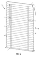
Figure 1 is front perspective view of a first present preferred embodiment of a Venetian blind in a lowered, or extended position. The slats are shown tilted in a closed position. -
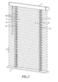
Figure 2 is a front perspective view of the first present preferred embodiment of the blind shown in an extended, or lowered, position. The slats are shown in an open position. -
Figure 3 is a front perspective view of the first present preferred embodiment of the blind with the window covering material in a retracted position. -
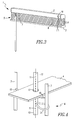
Figure 4 is a fragmentary side view of the first present preferred embodiment of the blind illustrating a slat positioned on a rung of a ladder and a cord shroud attached to the ladder and the cord shroud and lift cord passing through holes in the slats. -
Figure 5 is a fragmentary side view similar toFigure 4 illustrating an alternative embodiment of the blind in which slats may be positioned on the rungs of a ladder, a cord shroud may be attached to the ladder and the cord shroud and lift cord may pass along an edge of each of the slats. -
Figure 6 is a fragmentary side view similar toFigures 4 and5 illustrating another alternative embodiment of the blind in which, for each slat, the slat may be positioned on rungs of a ladder and a cord shroud may extend through the gap defined between the rungs of the ladder while also passing through holes in the slats. A portion of the slat illustrated inFigure 6 is cut away to better illustrate the cord shroud passing through the slat. -
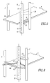
Figure 7 is a fragmentary side view illustrating yet another alternative embodiment of the blind in which a cord shroud functions as a rail for a ladder. -
Figure 8 is a fragmentary view similar toFigure 7 illustrating another embodiment of the blind in which a ladder has one rail that is a cord shroud and another rail that is composed of a flexible elongated member such as a cord or tape material. - Referring to
Figures 1-4 , a blind 1 may include aheadrail 2, abottom rail 3, andwindow covering material 5 that extends between theheadrail 2 and thebottom rail 3. Thewindow covering material 5 may includeslats 4 that are positioned on rungs of a plurality ofladders 6. The slats may be composed of metal, such as aluminum, or may be composed of plastic. - A
cord lock 19 or other lift cord control mechanism may be attached to the headrail to control movement of lift cords that extend from theheadrail 2 to thebottom rail 3. The lift cords may pass through thewindow covering material 5 by passing through holes in theslats 4 or may pass alongside thewindow covering material 5 by passing alongside an edge of each slat. It should be understood that alternative embodiments of the blind that do not utilize a bottom rail may have the lift cords extend to the lowermost slat of the window covering material. - The lift cords may be wound and unwound from a shaft in the headrail or be wound and unwound from one or more spools positioned in the headrail. Winding of the lift cords raises the blind, or retracts the window covering material. Unwinding of the lift cords extends the window covering material, or lowers the blind. Lift cords may be lifting tape, cord material, elongated straps having a width of between 2.54 and 7.62 cm (between 1 and three inches), or may be other flexible elongated members.
- The
ladders 6 may include a first ladder and a second ladder. The first ladder may havefirst rails 7 andrungs 10 that extend between the pair offirst rails 7. Thefirst rails 7 may include a front rail positioned on the front face of the window covering material and a rear rail positioned on the rear face of the window covering material. - The second ladder may have
second rails 9 and rungs that extend between the pair ofsecond rails 9. One second rail may be positioned on the front face of the window covering material and the other second rail may be on the rear face of the window covering material. - The rungs of the ladders support the
slats 4. The ladders may be attached to a tilt mechanism located in or attached to the headrail that is actuated by a tilt rod or other actuation device so that the ladders may be moved to tilt theslats 4 from a closed position, as shown inFigure 1 to an open position, as shown inFigure 2 . - The
rails - The portion of each lift cord that extends out of the
headrail 2 and to thebottom rail 3 is enclosed by a cord shroud. For example, afirst lift cord 11 is enclosed by afirst cord shroud 13 and asecond lift cord 12 is enclosed by asecond cord shroud 15. The cord shrouds may be series of webs extending between spaced apart rungs to define a generally tubular structure. As another example, each cord shroud may be a tubular cloth structure or tubular structure having a mesh surface. In alternative designs, the cord shrouds may be spiral structures defining an aperture through which a portion of a lift cord passes. The cord shrouds may be composed of a cloth material, mesh material, or interwoven filaments. The cord shrouds may fully enclose the portion of the lift cord or, alternatively, may substantially enclose a lift cord. - Each of the cord shrouds may have a top end attached to the
headrail 2 and a bottom end attached to thebottom rail 3. In embodiments that do not have abottom rail 3, the bottom end of the cord shroud may be attached to the lowermost slat. - The cord shrouds are also attached to the ladders of the blind 1. For example, the cord shrouds for each lift cord may be attached to the ladder adjacent to that lift cord. The cord shroud may be attached to the ladder at spaced apart locations by loops, adjustable loops, adjustable zip ties, zip ties, rings, sewn connections, sewn connectors, or other fasteners or fastening mechanisms. Each cord shroud may be attached to the one or both rails of a ladder, to one or more rungs of the ladder, or to all the rungs of the ladder. Of course, a cord shroud could also be attached to at least one rail of the ladder and at least some of the rungs of the ladder as well.
- Referring to
Figure 4 , each cord shroud may be attached to a rail of the respective ladder to which the cord shroud is adjacent. For instance, thefirst cord shroud 13 that encloses a portion of thefirst lift cord 11 that extends from theheadrail 2 to thebottom rail 3 may be attached to arail 7 of the ladder adjacent to that cord shroud.Loops 21 may extend from thefirst cord shroud 13 to therail 7. Theloops 21 may be spaced apart by a predetermined distance to provide a number of different locations of attachment to therail 7. For instance, theloops 21 may each be 10.16 cm, 12.7 cm, or 15.24 cm (4 inches, 5 inches, or 6 inches) away from a loop that is immediately below or above that loop. As another example, theloops 21 may be positioned to attach the cord shroud to a junction of a rung and a rail on a periodic basis, such as having such a connection formed on the rail at every other rung. Preferably, the attachment locations are positioned to prevent the cord shroud from being pulled away from theslats 4 to form a loop of over 15.24 cm (six inches) in diameter or over 20.32 cm (eight inches) in diameter. - As may be appreciated from
Figure 4 , the cord shrouds and lift cords may pass through each of the slats by passing throughholes 17 in the slats. Alternatively, the cord shrouds and lift cords may pass adjacent to an edge of the slats or along an edge of the slats, as may be appreciated fromFigure 5 . For such embodiments,loops 23 may extend from the cord shroud torungs 10 of the ladder adjacent that cord shroud. Additionally, loops or rings 24 may extend from the cord shroud to attach the cord shroud to a rail of the ladder at different locations. As discussed above, the locations at which the cord shroud is attached to the ladder are spaced apart to prevent the formation of a loop that may pose an entanglement danger to small children. - In yet another alterative shown in
Figure 6 , thecord shroud 13 andlift cord 11 may pass through holes in the slats and also pass throughgaps 10a formed between rungs of the ladder adjacent the cord shroud. For example, multiple rungs may extend between a pair of rails to support a portion of aslat 4. Agap 10a may be defined between these rungs. The lift cord and cord shroud may extend through a hole in the slat and also pass through thegap 10a. - Referring to
Figure 7 , it is also contemplated thatladders 30 of the blind may have rails that also function as cord shrouds. For instance, an embodiment of the blind may includeslats 4 that are supported onrungs 10. Therungs 10 may extend between two rails. The rails may be tubular structures that have mesh surfaces that are capable of functioning as cord shrouds. Alift cord 31 may pass through one of the rails that functions as and is acord shroud 32. In some embodiments, a second lift cord (not shown) may pass through the opposite rail that functions as a cord shroud as well. Thecord shroud 32 may enclose a portion of thelift cord 31 that extends out of the headrail of a blind and to a bottom rail or lowermost slat while also being periodically attached to the ladder via therungs 10 attached to the opposite rail. Such periodic attachment of the cord shroud to the opposite rail by the rungs can prevent the pulling away of the enclosed portion of the lift cord to form a dangerous loop. - In alternative embodiments it is contemplated that the ladders may include rails defined by
cords 37 that pass through the cord shrouds 32 to form rails of the ladder that are attached to therungs 10. For such an embodiment, the cord shrouds may cover a portion of respective ones of thelift cords 31 and also cover a portion of therails 37. - Referring to
Figure 8 , another alternative embodiment of my blind may include a ladder that only uses onecord shroud 32 that may either also function as a rail or, alternatively, may be positioned so that thecord shroud 32 covers both alift cord 31 and acord 37 that functions as a rail for a ladder. The rail opposite thecord shroud 32, however, may only be acord 37. Thecord shroud 32 may function as a rail of the ladder and be periodically attached to therail 37 via therungs 10 to prevent the lift cord enclosed by thecord shroud 32 from being pulled away form the slats to form a loop that may be dangerous to a small child. - Such an embodiment may be configured so that after the blind is mounted adjacent to a window, the cord shrouds are positioned adjacent the window on a rear side of the blind to hide the cord shrouds from view from a person in a room. The blind may then appear to the user in the room as a typical venetian blind while also providing the protection afforded by the cord shroud covering the lift cord and preventing the substantial pulling of lift cords away from the
slats 4 that have the potential for leading to an occurrence of a dangerous child entanglement with such a pulled lift cord. - It should be appreciated that a blind may have any number of lift cords, ladders for supporting the slats, and cord shrouds. The number of lift cords, ladders, and cord shrouds used may depend on a number of design and aesthetic options, such as the size of the blind and the length and weight of the slats.
- It should be appreciated that alternative lift cord control mechanisms may be utilized instead of a cord lock in other embodiments of the blind. For example, lift cord control mechanisms such as spring motor arrangements used in cordless shades, motors, or other lift cord control systems may be utilized in some embodiments of the blind.
- While certain present preferred embodiments of the window covering and certain embodiments of methods of practicing the same have been shown and described, it is to be distinctly understood that the invention is not limited thereto but may be otherwise variously embodied and practiced within the scope of the following claims.
Claims (15)
- A blind comprising:a headrail;a plurality of ladders extending from the headrail each ladder comprised of a column of rungs extending between two spaced apart rails;a plurality of slats supported on the ladders the plurality of slats comprising a lowermost slat which is positioned furthest from the headrail;a plurality of lift cords extending from the headrail, each lift cord being adjacent to one of the plurality of ladders and extending to the lowermost slat; anda plurality of cord shrouds, each of the cord shrouds enclosing a portion of one of the lift cords that extends from the headrail to a position adjacent to the lowermost slat and the cord shroud being attached to the ladder which is adjacent the lift cord enclosed by the cord shroud.
- The blind of claim 1 wherein each of the cord shrouds is attached to a respective one of the ladders at spaced apart positions, preferably each of the cord shrouds being attached to at least one of the rails of a respective one of the ladders.
- The blind of claim 1 or 2 further comprising a plurality of fasteners, each of the fasteners attaching one of the cord shrouds to one of the rails or one of the rungs.
- The blind of any of the preceding claims wherein the lift cords and cord shrouds extend through the slats, preferably the lift cords and cord shrouds extending adjacent to an edge of each of the slats.
- The blind of any of the preceding claims wherein each of the cord shrouds is attached to a respective one of the ladders by being attached to the rungs of a respective one of the ladders, preferably each of the cord shrouds being attached to each and every one of the rungs of the respective one of the ladders.
- The blind of any of the preceding claims further comprising a bottom rail, the portion of each of the lift cords extending to the bottom rail.
- The blind of any of the preceding claims wherein at least one of the rails for each of the ladders is one of the cord shrouds, preferably the ladders being comprised of cord material or strands of cord material.
- The blind of any of the preceding claims wherein each of the rails of the ladders is a flexible elongated member.
- The blind of any of the preceding claims wherein each of the cord shrouds is attached to a plurality of the rungs or at least one of the rails of a respective one of the ladders, preferably each of the cord shrouds having a first end and a second end opposite the first end, the first end attached to the headrail and the second end attached to the lowermost slat, and/or preferably each of the cord shrouds and each of the lift cords extending through gaps defined between adjacent rungs of a respective one of the ladders,.
- The blind of any of the preceding claims wherein each of the cord shrouds is attached to a respective one of the ladders at spaced apart locations such that spacing between immediately adjacent locations of attachment between the cord shroud and the ladder prevents the cord shroud from being pulled away from the slats to form a loop that is over 15.24 cm (six inches) in diameter.
- The blind of any of the preceding claims wherein rings or loops extend from each of the cord shrouds to connect the cord shrouds to the ladders, preferably the loops being adjustable loops or zip ties.
- The blind of any of the preceding claims further comprising a bottom rail, the portion of each of the lift cords extending to the bottom rail and wherein each of the cord shrouds has a first end and a second end opposite the first end, the first end attached to the headrail and the second end attached to the bottom rail.
- A blind comprising:a first rail;a plurality of ladders extending from the first rail;a plurality of slats, the plurality of slats comprising a lowermost slat which is positioned furthest from the first rail;a plurality of lift cords extending from the first rail, each lift cord being adjacent to one of the plurality of ladders and extending to the lowermost slat; andwherein each of the ladders is comprised of at least one cord shroud and a column of rungs attached to the at least one cord shroud, the rungs supporting the slats, the at least one cord shroud enclosing a portion of one of the lift cords that extends from the first rail to a position adjacent to the lowermost slat.
- The blind of claim 13 wherein each of the ladders is comprised of only one cord shroud and is further comprised of an elongated flexible member that extends from the first rail to a position adjacent to the lowermost slat, the rungs of the ladder extending between the flexible elongated member and the cord shroud to support the slats, the at least one cord shroud being attached to the flexible elongated member by the rungs such that the lift cord enclosed by the cord shroud is prevented from being pulled away from the slats to form a loop having a diameter of greater than 15.24 cm (six inches).
- The blind of claim 13 or 14 further comprising a bottom rail and wherein each of the ladders is comprised of only one cord shroud and is further comprised of an elongated flexible member that extends from the first rail to a position adjacent to the lowermost slat, the rungs of the ladder extending between the flexible elongated member and the cord shroud to support the slats, preferably each cord shroud being comprised of a series of webs that define a generally tubular structure or being a tubular structure having a mesh surface.
Applications Claiming Priority (1)
| Application Number | Priority Date | Filing Date | Title |
|---|---|---|---|
| US13/214,515 US20130048233A1 (en) | 2011-08-22 | 2011-08-22 | Blind Having Cord Shrouds |
Publications (2)
| Publication Number | Publication Date |
|---|---|
| EP2562345A2 true EP2562345A2 (en) | 2013-02-27 |
| EP2562345A3 EP2562345A3 (en) | 2015-07-29 |
Family
ID=46799965
Family Applications (1)
| Application Number | Title | Priority Date | Filing Date |
|---|---|---|---|
| EP12005966.2A Withdrawn EP2562345A3 (en) | 2011-08-22 | 2012-08-21 | Blind having cord shrouds |
Country Status (3)
| Country | Link |
|---|---|
| US (1) | US20130048233A1 (en) |
| EP (1) | EP2562345A3 (en) |
| CA (1) | CA2783860A1 (en) |
Cited By (2)
| Publication number | Priority date | Publication date | Assignee | Title |
|---|---|---|---|---|
| WO2015155267A1 (en) * | 2014-04-10 | 2015-10-15 | Inwido Ab | Ladder cord assembly for venetian blind |
| TWI706079B (en) * | 2019-10-02 | 2020-10-01 | 范富美 | Venetian blinds and lower rails |
Families Citing this family (12)
| Publication number | Priority date | Publication date | Assignee | Title |
|---|---|---|---|---|
| WO2013147039A1 (en) * | 2012-03-30 | 2013-10-03 | 立川ブラインド工業 株式会社 | Horizontal blind and method for manufacturing horizontal blind |
| US9359812B2 (en) | 2014-09-05 | 2016-06-07 | Whole Space Indsutries Ltd. | Window covering |
| USD773208S1 (en) | 2014-09-22 | 2016-12-06 | Whole Space Industries Ltd | Window covering |
| TWM527914U (en) * | 2016-04-25 | 2016-09-01 | Ching Feng Home Fashions Co | Curtain body safety string structure |
| US10975618B2 (en) | 2017-07-26 | 2021-04-13 | Whole Space Industries Ltd | Slat tilt mechanism for window coverings |
| US10550635B2 (en) | 2017-08-09 | 2020-02-04 | Whole Space Industries Ltd | Window covering control apparatus |
| US10676988B2 (en) | 2017-09-20 | 2020-06-09 | Whole Space Industries Ltd. | Window covering control apparatus |
| US20190112872A1 (en) * | 2017-10-18 | 2019-04-18 | Sheng Ying Hsu | Rope assembly for window blinds |
| KR102026066B1 (en) * | 2017-11-24 | 2019-09-27 | 곽재석 | Cordless safety blind |
| US20190277085A1 (en) * | 2018-03-09 | 2019-09-12 | Ya-Yin Lin | Pull cord safety device for a window covering |
| USD935221S1 (en) | 2019-06-26 | 2021-11-09 | Whole Space Industries Ltd | Bottom rail for a window covering |
| MX2023000240A (en) * | 2020-06-18 | 2023-03-03 | Hunter Douglas | Ladder tape assemblies with cord shroud arrangements for slatted blinds. |
Citations (20)
| Publication number | Priority date | Publication date | Assignee | Title |
|---|---|---|---|---|
| US4909298A (en) | 1988-09-26 | 1990-03-20 | Langhart Richard M | Window covering cord pull safety device |
| US5495883A (en) | 1994-08-05 | 1996-03-05 | Verosol Usa Inc. | Window shade cord safety shroud |
| US5533559A (en) | 1995-02-06 | 1996-07-09 | Judkins; Ren | Window shade assembly with hold down |
| US5613540A (en) | 1994-08-05 | 1997-03-25 | Verosol Usa Inc. | Window shade cord safety shroud |
| US5630458A (en) | 1996-04-05 | 1997-05-20 | Holden; Miles A. | System for childproofing window closures |
| US6431248B1 (en) | 2000-11-03 | 2002-08-13 | Lewis Hyman, Inc. | Releasable cord connection apparatus |
| US6484787B1 (en) | 2000-11-17 | 2002-11-26 | Paul A. Walters | Window blind cord storage member |
| US6637493B1 (en) | 2002-04-05 | 2003-10-28 | Nicholas Lampers | Device and method for holding window covering pull cords |
| US6860312B2 (en) | 2002-09-27 | 2005-03-01 | Ren Judkins | Roll-up shade with cord capture |
| US6918425B2 (en) | 2003-08-28 | 2005-07-19 | Leslie Nien | Non-pull cord operable venetian blind |
| US6948546B2 (en) | 2003-11-28 | 2005-09-27 | Leslie Nien | Cord retaining device for non-cord venetian blind |
| US7000672B2 (en) | 2003-10-17 | 2006-02-21 | Leslie Nien | Venetian blind operated with non-pull cord structure |
| US20060144526A1 (en) | 2003-07-09 | 2006-07-06 | Caprice Window Accessories Pty Ltd. | Window cover |
| US7086446B2 (en) | 2003-12-30 | 2006-08-08 | Lumino, Inc. | Breakaway cord system for roll-up shades |
| US7117918B2 (en) | 2003-10-24 | 2006-10-10 | Hunter Douglas Industries Bv | Mounting device for a guide cord |
| US20070023149A1 (en) | 2005-07-26 | 2007-02-01 | Hunter Douglas Industries Bv | Cord anchor |
| US7225850B2 (en) | 2003-03-21 | 2007-06-05 | 3 Day Blinds, Inc. | Child safety blind |
| US7261138B2 (en) | 2003-12-02 | 2007-08-28 | Ren Judkins | Child safe cord lock |
| US7318251B2 (en) | 2003-05-13 | 2008-01-15 | Lewis Hyman, Inc. | Safety buckle of curtain |
| US20080110581A1 (en) | 2006-11-15 | 2008-05-15 | Tzong-Fu Lin | Safety mechanism for window blind |
Family Cites Families (7)
| Publication number | Priority date | Publication date | Assignee | Title |
|---|---|---|---|---|
| US5769140A (en) * | 1996-09-17 | 1998-06-23 | Tuzmen; Zeki | Holeless window blind |
| US5918657A (en) * | 1996-09-17 | 1999-07-06 | Tuzmen; Zeki | Holeless window blind |
| US5727613A (en) * | 1996-11-12 | 1998-03-17 | Judkins; Ren | Ladder for venetian type blinds |
| US5743319A (en) * | 1997-01-07 | 1998-04-28 | Christopherson; Herman P. | Window blind with safety pull cord |
| US6119314A (en) * | 1999-03-09 | 2000-09-19 | Freed; Anna B. | Multi-function tie |
| US7556080B2 (en) * | 2007-01-30 | 2009-07-07 | Nien Made Enterprise Co., Ltd. | Blind and its assembling method |
| US20110209834A1 (en) * | 2010-03-01 | 2011-09-01 | Lowry John R | Window Covering Apparatus |
-
2011
- 2011-08-22 US US13/214,515 patent/US20130048233A1/en not_active Abandoned
-
2012
- 2012-07-30 CA CA2783860A patent/CA2783860A1/en active Pending
- 2012-08-21 EP EP12005966.2A patent/EP2562345A3/en not_active Withdrawn
Patent Citations (20)
| Publication number | Priority date | Publication date | Assignee | Title |
|---|---|---|---|---|
| US4909298A (en) | 1988-09-26 | 1990-03-20 | Langhart Richard M | Window covering cord pull safety device |
| US5495883A (en) | 1994-08-05 | 1996-03-05 | Verosol Usa Inc. | Window shade cord safety shroud |
| US5613540A (en) | 1994-08-05 | 1997-03-25 | Verosol Usa Inc. | Window shade cord safety shroud |
| US5533559A (en) | 1995-02-06 | 1996-07-09 | Judkins; Ren | Window shade assembly with hold down |
| US5630458A (en) | 1996-04-05 | 1997-05-20 | Holden; Miles A. | System for childproofing window closures |
| US6431248B1 (en) | 2000-11-03 | 2002-08-13 | Lewis Hyman, Inc. | Releasable cord connection apparatus |
| US6484787B1 (en) | 2000-11-17 | 2002-11-26 | Paul A. Walters | Window blind cord storage member |
| US6637493B1 (en) | 2002-04-05 | 2003-10-28 | Nicholas Lampers | Device and method for holding window covering pull cords |
| US6860312B2 (en) | 2002-09-27 | 2005-03-01 | Ren Judkins | Roll-up shade with cord capture |
| US7225850B2 (en) | 2003-03-21 | 2007-06-05 | 3 Day Blinds, Inc. | Child safety blind |
| US7318251B2 (en) | 2003-05-13 | 2008-01-15 | Lewis Hyman, Inc. | Safety buckle of curtain |
| US20060144526A1 (en) | 2003-07-09 | 2006-07-06 | Caprice Window Accessories Pty Ltd. | Window cover |
| US6918425B2 (en) | 2003-08-28 | 2005-07-19 | Leslie Nien | Non-pull cord operable venetian blind |
| US7000672B2 (en) | 2003-10-17 | 2006-02-21 | Leslie Nien | Venetian blind operated with non-pull cord structure |
| US7117918B2 (en) | 2003-10-24 | 2006-10-10 | Hunter Douglas Industries Bv | Mounting device for a guide cord |
| US6948546B2 (en) | 2003-11-28 | 2005-09-27 | Leslie Nien | Cord retaining device for non-cord venetian blind |
| US7261138B2 (en) | 2003-12-02 | 2007-08-28 | Ren Judkins | Child safe cord lock |
| US7086446B2 (en) | 2003-12-30 | 2006-08-08 | Lumino, Inc. | Breakaway cord system for roll-up shades |
| US20070023149A1 (en) | 2005-07-26 | 2007-02-01 | Hunter Douglas Industries Bv | Cord anchor |
| US20080110581A1 (en) | 2006-11-15 | 2008-05-15 | Tzong-Fu Lin | Safety mechanism for window blind |
Cited By (2)
| Publication number | Priority date | Publication date | Assignee | Title |
|---|---|---|---|---|
| WO2015155267A1 (en) * | 2014-04-10 | 2015-10-15 | Inwido Ab | Ladder cord assembly for venetian blind |
| TWI706079B (en) * | 2019-10-02 | 2020-10-01 | 范富美 | Venetian blinds and lower rails |
Also Published As
| Publication number | Publication date |
|---|---|
| CA2783860A1 (en) | 2013-02-22 |
| EP2562345A3 (en) | 2015-07-29 |
| US20130048233A1 (en) | 2013-02-28 |
Similar Documents
| Publication | Publication Date | Title |
|---|---|---|
| EP2562345A2 (en) | Blind having cord shrouds | |
| US9382753B2 (en) | Window covering | |
| EP2469008B1 (en) | Window covering | |
| EP2472049A2 (en) | Window covering with cord shrouds | |
| US8113261B2 (en) | Window covering | |
| EP2374983B1 (en) | Foldable roller blind | |
| EP2479374B1 (en) | Window covering | |
| US20110024065A1 (en) | Window Covering | |
| US20100126673A1 (en) | Window Covering Having at Least One Cord Release Device | |
| US9719295B2 (en) | Window covering | |
| US9759009B2 (en) | Window covering | |
| US8684063B2 (en) | Window covering having cord shrouds | |
| US20100126677A1 (en) | Window Covering | |
| US20160069130A1 (en) | Cordless blind system and retro-fit method | |
| US20120132373A1 (en) | Window Covering | |
| EP2221443B1 (en) | A window covering | |
| CA3178817A1 (en) | Operating device for a window covering | |
| EP2514910B1 (en) | Window covering | |
| CA3150930A1 (en) | Roman blind with flexible flat member | |
| WO2013191553A1 (en) | Blind |
Legal Events
| Date | Code | Title | Description |
|---|---|---|---|
| PUAI | Public reference made under article 153(3) epc to a published international application that has entered the european phase |
Free format text: ORIGINAL CODE: 0009012 |
|
| AK | Designated contracting states |
Kind code of ref document: A2 Designated state(s): AL AT BE BG CH CY CZ DE DK EE ES FI FR GB GR HR HU IE IS IT LI LT LU LV MC MK MT NL NO PL PT RO RS SE SI SK SM TR |
|
| AX | Request for extension of the european patent |
Extension state: BA ME |
|
| PUAL | Search report despatched |
Free format text: ORIGINAL CODE: 0009013 |
|
| AK | Designated contracting states |
Kind code of ref document: A3 Designated state(s): AL AT BE BG CH CY CZ DE DK EE ES FI FR GB GR HR HU IE IS IT LI LT LU LV MC MK MT NL NO PL PT RO RS SE SI SK SM TR |
|
| AX | Request for extension of the european patent |
Extension state: BA ME |
|
| RIC1 | Information provided on ipc code assigned before grant |
Ipc: E06B 9/326 20060101AFI20150625BHEP |
|
| STAA | Information on the status of an ep patent application or granted ep patent |
Free format text: STATUS: THE APPLICATION IS DEEMED TO BE WITHDRAWN |
|
| 18D | Application deemed to be withdrawn |
Effective date: 20160130 |