EP2562058A2 - Dispositif d'appui monté de manière modulaire pour un semi-remorque et semi-remorque doté d'un tel dispositif d'appui - Google Patents
Dispositif d'appui monté de manière modulaire pour un semi-remorque et semi-remorque doté d'un tel dispositif d'appui Download PDFInfo
- Publication number
- EP2562058A2 EP2562058A2 EP12179181A EP12179181A EP2562058A2 EP 2562058 A2 EP2562058 A2 EP 2562058A2 EP 12179181 A EP12179181 A EP 12179181A EP 12179181 A EP12179181 A EP 12179181A EP 2562058 A2 EP2562058 A2 EP 2562058A2
- Authority
- EP
- European Patent Office
- Prior art keywords
- support tube
- actuating
- outer support
- spindle
- spindle mechanism
- Prior art date
- Legal status (The legal status is an assumption and is not a legal conclusion. Google has not performed a legal analysis and makes no representation as to the accuracy of the status listed.)
- Granted
Links
- 230000005540 biological transmission Effects 0.000 claims description 20
- 238000005096 rolling process Methods 0.000 claims description 2
- 230000033001 locomotion Effects 0.000 description 6
- 238000010276 construction Methods 0.000 description 4
- 238000002788 crimping Methods 0.000 description 2
- 230000006978 adaptation Effects 0.000 description 1
- 150000001875 compounds Chemical class 0.000 description 1
- 230000001419 dependent effect Effects 0.000 description 1
- 238000004519 manufacturing process Methods 0.000 description 1
- 125000006850 spacer group Chemical group 0.000 description 1
- 238000003466 welding Methods 0.000 description 1
Images

Classifications
-
- B—PERFORMING OPERATIONS; TRANSPORTING
- B62—LAND VEHICLES FOR TRAVELLING OTHERWISE THAN ON RAILS
- B62D—MOTOR VEHICLES; TRAILERS
- B62D63/00—Motor vehicles or trailers not otherwise provided for
- B62D63/06—Trailers
- B62D63/08—Component parts or accessories
-
- B—PERFORMING OPERATIONS; TRANSPORTING
- B60—VEHICLES IN GENERAL
- B60S—SERVICING, CLEANING, REPAIRING, SUPPORTING, LIFTING, OR MANOEUVRING OF VEHICLES, NOT OTHERWISE PROVIDED FOR
- B60S9/00—Ground-engaging vehicle fittings for supporting, lifting, or manoeuvring the vehicle, wholly or in part, e.g. built-in jacks
- B60S9/02—Ground-engaging vehicle fittings for supporting, lifting, or manoeuvring the vehicle, wholly or in part, e.g. built-in jacks for only lifting or supporting
- B60S9/04—Ground-engaging vehicle fittings for supporting, lifting, or manoeuvring the vehicle, wholly or in part, e.g. built-in jacks for only lifting or supporting mechanically
- B60S9/06—Ground-engaging vehicle fittings for supporting, lifting, or manoeuvring the vehicle, wholly or in part, e.g. built-in jacks for only lifting or supporting mechanically of screw-and-nut type
- B60S9/08—Ground-engaging vehicle fittings for supporting, lifting, or manoeuvring the vehicle, wholly or in part, e.g. built-in jacks for only lifting or supporting mechanically of screw-and-nut type the screw axis being substantially vertical
-
- Y—GENERAL TAGGING OF NEW TECHNOLOGICAL DEVELOPMENTS; GENERAL TAGGING OF CROSS-SECTIONAL TECHNOLOGIES SPANNING OVER SEVERAL SECTIONS OF THE IPC; TECHNICAL SUBJECTS COVERED BY FORMER USPC CROSS-REFERENCE ART COLLECTIONS [XRACs] AND DIGESTS
- Y10—TECHNICAL SUBJECTS COVERED BY FORMER USPC
- Y10T—TECHNICAL SUBJECTS COVERED BY FORMER US CLASSIFICATION
- Y10T74/00—Machine element or mechanism
- Y10T74/18—Mechanical movements
- Y10T74/18568—Reciprocating or oscillating to or from alternating rotary
- Y10T74/18784—Reciprocating or oscillating to or from alternating rotary including bevel gears
Definitions
- the invention relates to a support device for a semi-trailer or the like, a semi-trailer with at least one such support device, and an actuating device and a transmission device for use in such a support device.
- a support device of the type in question is used to support a semitrailer when it is disconnected from the tractor, with the support mostly two support devices (pair of supports) are used on a semi-trailer.
- a support device is z. B. from the DE 20 2006 012 472 U1 known.
- the known support device comprises an outer support tube and an inner support tube, wherein the inner support tube is telescopically disposed in the outer support tube and by means of a built inside (ie inside the tube) spindle mechanism in the axial direction relative to the outer support tube can be moved.
- the actuation of the spindle mechanism is effected by an actuating device arranged in the interior of the outer support tube, with which a rotational movement generated by means of a hand crank or the like can be converted into a spindle rotational movement.
- a disadvantage of the previously known support device is a relatively high construction cost, especially in view of the fact that often an individual adaptation to the respective semi-trailer is required.
- the support device according to the invention has a straight outer support tube and a straight inner support tube, wherein the inner support tube is telescopically arranged in the outer support tube and can be moved by means of a built-in spindle mechanism in the axial direction relative to the outer support tube. It is envisaged that the support device according to the invention further comprises an actuating device for actuating the spindle mechanism, which is formed as a separate structural unit and which is arranged outside of the outer support tube.
- the invention is based on the idea no longer to arrange the actuator for actuating the spindle mechanism in the outer support tube, which is self-explanatory connected with a certain amount of construction, but to provide as a separate unit or as a separate structural module.
- the Supporting device according to the invention thus has a modular construction.
- the trained as a separate unit actuator for actuating the spindle mechanism (hereinafter also referred to only as actuator) preferably has its own housing.
- the outer support tube and the inner support tube can be individually cut to length. Subsequently, the inner support tube, the outer support tube, the spindle mechanism (or its individual components) and the separate actuator for the spindle mechanism can be assembled with relatively little effort.
- the invention also makes it possible to create a modular system comprising only a few components, with which supporting devices according to the invention can be assembled flexibly or as needed.
- This modular system includes z. B. provided by the meter outer support tubes and inner support tubes (in particular with a rectangular cross-section), spindles in different lengths (and / or cut-off spindles) and designed as a separate unit actuators for actuating the spindle mechanism, with different types of such actuators (eg. With or without a Herein Transmission gear, as explained in more detail below) may be included.
- the targeted combination of these components makes it possible to produce support devices according to the invention with a large variety of variants.
- the trained as a separate unit actuator for actuating the spindle mechanism may be connected to the outer support tube. It is preferably provided that the formed as a separate unit actuator for the spindle mechanism attached directly to the upper end or an upper portion of the outer support tube, z. B. is flanged. The upper end face is that of the lower end face, from which protrudes the telescoping inner support tube, opposite end face.
- the actuator may be bolted to the outer support tube, welded, riveted and / or crimped. Under a crimping is a through understood plastic deformation induced compound.
- positive-locking elements such as. B. an interlocking toothing can be provided.
- a connection between the actuating device and the outer support tube can also take place via a mounting plate located on the outer support tube (for fastening the support device according to the invention on the semitrailer).
- the mounting plate may project beyond the upper side or front side of the outer support tube. This projecting region of the mounting plate then serves as a mounting region on which the actuating device can be fixed.
- an intermediate piece for example a spacer tube
- the actuator designed as a separate unit for actuating the spindle mechanism has at least one input shaft for a hand crank and / or a drive motor, and a transfer gear, in particular a bevel gear, which converts a rotational movement on the input shaft in a spindle rotation.
- the trained as a separate unit actuator for actuating the spindle mechanism may have a switchable multi-speed transmission gear.
- a switchable multi-speed transmission allows z.
- overdrive and a so-called load gear including in the following on the DE 20 2006 012 472 U1 is referenced.
- the support device according to the invention further comprises a transmission device with a switchable multi-speed transmission, which is designed as a separate unit and which is flanged to the separately formed actuator.
- this transmission device is arranged between the separately formed actuating device and the outer support tube.
- a gear unit designed as a separate structural unit preferably has its own housing.
- the trained as a separate unit actuator and designed as a separate unit gear unit are flanged directly by means of their housing with each other.
- the connection can be achieved by screwing, welding, riveting and / or crimping.
- positive-locking elements such as. B. an interlocking toothing can be provided.
- the spindle mechanism of the support device comprises a spindle, which is preferably inserted or inserted from below into the actuator formed as a separate component or in the formed as a separate component gear and with at least one arranged there (belonging to the actuator or transmission device) roller bearings in the axial direction and / or is supported in the radial direction.
- the Fig. 1 and 2 show a support device 100 according to the invention for a semi-trailer or the like.
- the support device 100 comprises an outer support tube 110 in which telescoping or longitudinally displaceable an inner support tube 120 is arranged, which protrudes from the outer support tube 110 at the lower end side.
- the outer support tube 110 and the Innst Reifenrohr 120 are formed with square cross-section.
- an unillustrated support leg or Ausreterated support leg or Ausreterated support leg or Ausreterated support leg or Ausreterated support leg or Ausreterated support leg or Ausmaschinesfuß is attached.
- 130 Denoted by 130 is a mounting plate or mounting plate, with which the support device 100 can be screwed to the frame of a semitrailer.
- the mounting plate 130 is, for example, welded to the outer support tube 110.
- an actuating device 140 is provided, which is designed as a separate structural unit and flanged axially aligned directly on the upper end face of the outer support tube 110 and is fixedly connected to the outer support tube 110. It is preferably provided that this actuator 140 is provided as a verbaufertige unit or component that z. B. may already be painted. For this purpose, the actuating device 140 may have its own housing.
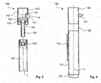
- Fig. 3 illustrates the function of the spindle mechanism and the structure of the actuator 140 for actuating this spindle mechanism.
- the outer support tube 110 is not shown.
- the spindle mechanism includes a spindle nut 150 fixedly or floatingly disposed at the upper axial end in the inner support tube 120, and a spindle 155 (eg, with a trapezoidal motion thread) that engages the spindle nut 150 (the engagement is not shown) and the spindle is attached to the actuator 140 at its upper axial end.
- the inner support tube 120 can be moved along the longitudinal axis L relative to the outer support tube 110.
- the inner support tube 120 is retracted into the outer support tube 110 or extended out of the outer support tube 110.
- the actuating device 140 comprises an input shaft 141 for a hand crank or a drive motor.
- the longitudinal or rotational axis M of Input shaft 141 extends perpendicular to the longitudinal or rotational axis L of the spindle 155.
- a first bevel gear 142 is rotatably mounted, which engages with its toothing in a second bevel gear 143, wherein the second bevel gear 143 rotatably connected to the spindle 155 is.
- the first (driving) bevel gear 142 and the second (driven) bevel gear 143 form a bevel gear, which converts a rotational movement on the input shaft 141 in a rotational movement of the spindle 155 and in a spindle rotation.
- the spindle 155 is inserted from below into the actuator 140 and rotatably connected directly or indirectly with the second bevel gear 143.
- a rolling bearing 144 is provided for axial and / or radial support of the upper axial end of the spindle 155.
- the upper spindle bearing is integrated into the actuator 140.
- Actuator 140 may include an integrated multi-speed variable ratio transmission as discussed above.
- Fig. 4 shows an alternative embodiment of a support device according to the invention with a transmission device 160, which has a switchable multi-speed transmission gear (see the corresponding above explanations).
- the transmission device 160 is also formed as a separate structural unit and aligned between the separately formed actuator 140 and the outer support tube 110 incorporated.
- the transmission device 160 could, for example, also be flanged laterally to the actuating device 140.
Landscapes
- Engineering & Computer Science (AREA)
- Mechanical Engineering (AREA)
- Chemical & Material Sciences (AREA)
- Combustion & Propulsion (AREA)
- Transportation (AREA)
- Vehicle Cleaning, Maintenance, Repair, Refitting, And Outriggers (AREA)
- Jib Cranes (AREA)
Abstract
Description
Die Erfindung betrifft eine Stützvorrichtung für einen Sattelanhänger bzw. Sattelauflieger oder dergleichen, einen Sattelanhänger mit wenigstens einer solchen Stützvorrichtung, sowie eine Betätigungseinrichtung und eine Getriebeeinrichtung zur Verwendung in einer solchen Stützvorrichtung.The invention relates to a support device for a semi-trailer or the like, a semi-trailer with at least one such support device, and an actuating device and a transmission device for use in such a support device.
Eine Stützvorrichtung der betreffenden Art dient der Abstützung eines Sattelanhängers, wenn dieser von der Sattelzugmaschine abgekoppelt ist, wobei für die Abstützung zumeist zwei Stützvorrichtungen (Stützenpaar) an einem Sattelanhänger verwendet werden. Eine solche Stützvorrichtung ist z. B. aus der
Nachteilig an der vorbekannten Stützvorrichtung ist ein verhältnismäßig hoher Bauaufwand, insbesondere auch im Hinblick darauf, dass häufig eine individuelle Anpassung an den jeweiligen Sattelanhänger erforderlich ist.A disadvantage of the previously known support device is a relatively high construction cost, especially in view of the fact that often an individual adaptation to the respective semi-trailer is required.
Es ist daher eine Aufgabe der vorliegenden Erfindung, eine Stützvorrichtung der eingangs genannten Art anzugeben, die sich mit geringem Bauaufwand herstellen lässt.It is therefore an object of the present invention to provide a support device of the type mentioned, which can be produced with low construction costs.
Diese Aufgabe wird gelöst mit einer erfindungsgemäßen Stützvorrichtung mit den Merkmalen des Anspruchs 1. Die vom Anspruch 1 abhängigen Ansprüche betreffen bevorzugte Ausgestaltungen und Weiterbildungen der erfindungsgemäßen Stützvorrichtung. Mit einem nebengeordneten Anspruch erstreckt sich die Lösung der Aufgabe auch auf einen Sattelanhänger, der wenigstens eine und bevorzugt zwei erfindungsgemäße Stützvorrichtungen, die zur gemeinsamen Betätigung auch durch eine Verbindungswelle miteinander verbunden sein können, aufweist. Mit zwei weiteren nebengeordneten Ansprüchen erstreckt sich die Lösung der Aufgabe auch auf eine als separate Baueinheit ausgebildete und im Wesentlichen verbaufertig bereitgestellte Betätigungseinrichtung sowie auf eine als separate Baueinheit ausgebildete und im Wesentlichen verbaufertig bereitgestellte Getriebeeinrichtung, die an einer erfindungsgemäßen Stützvorrichtung verwendet bzw. verbaut werden können. Die nachfolgenden Erläuterungen gelten analog für alle Erfindungsgegenstände.This object is achieved with a support device according to the invention with the features of claim 1. The dependent of claim 1 claims relate to preferred embodiments and refinements of the support device according to the invention. With a sibling claim, the solution of the problem also extends to a semi-trailer, the at least one and preferably two support devices according to the invention, which may be connected to the common operation by a connecting shaft having. With two further independent claims, the solution of the problem also extends to a designed as a separate unit and essentially verbaufertig provided actuator and trained as a separate unit and essentially verbaufertig provided transmission device that can be used or installed on a support device according to the invention. The following explanations apply analogously to all invention objects.
Die erfindungsgemäße Stützvorrichtung weist ein gerades Außenstützrohr und ein gerades Innenstützrohr auf, wobei das Innenstützrohr teleskopierbar im Außenstützrohr angeordnet ist und mittels eines im Inneren verbauten Spindelmechanismus in axialer Richtung relativ zum Außenstützrohr bewegt werden kann. Es ist vorgesehen, dass die erfindungsgemäße Stützvorrichtung ferner eine Betätigungseinrichtung zur Betätigung des Spindelmechanismus aufweist, die als separate Baueinheit ausgebildet und die außerhalb des Außenstützrohrs angeordnet ist.The support device according to the invention has a straight outer support tube and a straight inner support tube, wherein the inner support tube is telescopically arranged in the outer support tube and can be moved by means of a built-in spindle mechanism in the axial direction relative to the outer support tube. It is envisaged that the support device according to the invention further comprises an actuating device for actuating the spindle mechanism, which is formed as a separate structural unit and which is arranged outside of the outer support tube.
Der Erfindung liegt die Idee zugrunde, die Betätigungseinrichtung zur Betätigung des Spindelmechanismus nicht mehr im Außenstützrohr anzuordnen, was selbsterklärend mit einem gewissen Bauaufwand verbunden ist, sondern als separate Baueinheit bzw. als separates Baumodul bereit zu stellen. Die erfindungsgemäße Stützvorrichtung weist somit einen modularen Aufbau auf. Die als separate Baueinheit ausgebildete Betätigungseinrichtung zur Betätigung des Spindelmechanismus (nachfolgend auch nur als Betätigungseinrichtung bezeichnet) weist bevorzugt ein eigenes Gehäuse auf. Bei der Herstellung einer erfindungsgemäßen Stützvorrichtung können das Außenstützrohr und das Innenstützrohr individuell abgelängt werden. Nachfolgend können das Innenstützrohr, das Außenstützrohr, der Spindelmechanismus (bzw. dessen Einzelkomponenten) und die separate Betätigungseinrichtung für den Spindelmechanismus mit verhältnismäßig geringem Aufwand zusammengebaut werden.The invention is based on the idea no longer to arrange the actuator for actuating the spindle mechanism in the outer support tube, which is self-explanatory connected with a certain amount of construction, but to provide as a separate unit or as a separate structural module. The Supporting device according to the invention thus has a modular construction. The trained as a separate unit actuator for actuating the spindle mechanism (hereinafter also referred to only as actuator) preferably has its own housing. In the manufacture of a support device according to the invention, the outer support tube and the inner support tube can be individually cut to length. Subsequently, the inner support tube, the outer support tube, the spindle mechanism (or its individual components) and the separate actuator for the spindle mechanism can be assembled with relatively little effort.
Die Erfindung ermöglicht ferner die Schaffung eines nur wenige Komponenten umfassenden Baukastensystems, mit dem erfindungsgemäße Stützvorrichtungen flexibel bzw. bedarfsgerecht zusammengebaut werden können. Dieses Baukastensystem umfasst z. B. als Meterware bereitgestellte Außenstützrohre und Innenstützrohre (insbesondere mit einem Rechteckquerschnitt), Spindeln in verschiedenen Längen (und/oder ablängbare Spindeln) und als separate Baueinheit ausgebildete Betätigungseinrichtungen zur Betätigung des Spindelmechanismus, wobei verschiedene Bautypen solcher Betätigungseinrichtungen (bspw. mit oder ohne einem mehrgängigen Übersetzungsgetriebe, wie nachfolgend noch näher erläutert) umfasst sein können. Die gezielte Kombination dieser Komponenten ermöglicht das Herstellen von erfindungsgemäßen Stützvorrichtungen mit einer großen Variantenvielfalt.The invention also makes it possible to create a modular system comprising only a few components, with which supporting devices according to the invention can be assembled flexibly or as needed. This modular system includes z. B. provided by the meter outer support tubes and inner support tubes (in particular with a rectangular cross-section), spindles in different lengths (and / or cut-off spindles) and designed as a separate unit actuators for actuating the spindle mechanism, with different types of such actuators (eg. With or without a mehrgängigen Transmission gear, as explained in more detail below) may be included. The targeted combination of these components makes it possible to produce support devices according to the invention with a large variety of variants.
Die als separate Baueinheit ausgebildete Betätigungseinrichtung zur Betätigung des Spindelmechanismus kann mit dem Außenstützrohr verbunden sein. Bevorzugt ist vorgesehen, dass die als separate Baueinheit ausgebildete Betätigungseinrichtung für den Spindelmechanismus direkt an der oberen Stirnseite oder einem oberen Bereich am Außenstützrohr befestigt, z. B. angeflanscht ist. Die obere Stirnseite ist die der unteren Stirnseite, aus der das teleskopierbare Innenstützrohr herausragt, gegenüberliegende Stirnseite. Die Betätigungseinrichtung kann mit dem Außenstützrohr verschraubt, verschweißt, vernietet und/oder verbördelt sein. Unter einer Verbördelung wird eine durch plastische Verformung herbeigeführte Verbindung verstanden. Ergänzend können Formschlusselemente, wie z. B. eine ineinandergreifende Verzahnung, vorgesehen sein. Eine Verbindung zwischen der Betätigungseinrichtung und dem Außenstützrohr kann auch über eine am Außenstützrohr befindliche Montageplatte (zur Befestigung der erfindungsgemäßen Stützvorrichtung am Sattelanhänger) erfolgen. Hierbei kann die Montageplatte die obere Seite bzw. Stirnseite des Außenstützrohres überragen. Dieser überragende bzw. vorstehende Bereich der Montageplatte dient dann als Befestigungsbereich, an dem die Betätigungseinrichtung festgelegt werden kann. Ferner kann zwischen dem Außenstützrohr und der Betätigungseinrichtung ein Zwischenstück (bspw. ein Distanzrohr) angeordnet sein.The trained as a separate unit actuator for actuating the spindle mechanism may be connected to the outer support tube. It is preferably provided that the formed as a separate unit actuator for the spindle mechanism attached directly to the upper end or an upper portion of the outer support tube, z. B. is flanged. The upper end face is that of the lower end face, from which protrudes the telescoping inner support tube, opposite end face. The actuator may be bolted to the outer support tube, welded, riveted and / or crimped. Under a crimping is a through understood plastic deformation induced compound. In addition, positive-locking elements, such as. B. an interlocking toothing can be provided. A connection between the actuating device and the outer support tube can also take place via a mounting plate located on the outer support tube (for fastening the support device according to the invention on the semitrailer). In this case, the mounting plate may project beyond the upper side or front side of the outer support tube. This projecting region of the mounting plate then serves as a mounting region on which the actuating device can be fixed. Furthermore, an intermediate piece (for example a spacer tube) can be arranged between the outer support tube and the actuating device.
Bevorzugt ist vorgesehen, dass die als separate Baueinheit ausgebildete Betätigungseinrichtung zur Betätigung des Spindelmechanismus wenigstens eine Eingangswelle für eine Handkurbel und/oder einen Antriebsmotor aufweist, sowie ein Umsetzgetriebe, wie insbesondere ein Kegelradgetriebe, welches eine Drehbewegung an der Eingangswelle in eine Spindeldrehbewegung umsetzt.It is preferably provided that the actuator designed as a separate unit for actuating the spindle mechanism has at least one input shaft for a hand crank and / or a drive motor, and a transfer gear, in particular a bevel gear, which converts a rotational movement on the input shaft in a spindle rotation.
Die als separate Baueinheit ausgebildete Betätigungseinrichtung zur Betätigung des Spindelmechanismus kann ein schaltbares mehrgängiges Übersetzungsgetriebe aufweisen. Ein solches schaltbares mehrgängiges Übersetzungsgetriebe ermöglicht z. B. einen so genannten Schnellgang und einen so genannten Lastgang, wozu im Weiteren auf die
Besonders bevorzugt ist vorgesehen, dass die erfindungsgemäße Stützvorrichtung ferner eine Getriebeeinrichtung mit einem schaltbaren mehrgängigen Übersetzungsgetriebe aufweist, die als separate Baueinheit ausgebildet und die an die separat ausgebildete Betätigungseinrichtung angeflanscht ist. Bevorzugt ist diese Getriebeeinrichtung zwischen der separat ausgebildeten Betätigungseinrichtung und dem Außenstützrohr angeordnet. Bevorzugt weist eine solche als separate Baueinheit ausgebildete Getriebeeinrichtung ein eigenes Gehäuse auf. Insbesondere ist vorgesehen, dass die als separate Baueinheit ausgebildete Betätigungseinrichtung und das als separate Baueinheit ausgebildete Übersetzungsgetriebe mittels ihrer Gehäuse direkt miteinander verflanscht sind. Die Verbindung kann durch Verschrauben, Verschweißen, Vernieten und/oder Verbördeln erzielt werden. Ergänzend können Formschlusselemente, wie z. B. eine ineinandergreifende Verzahnung, vorgesehen sein.It is particularly preferred that the support device according to the invention further comprises a transmission device with a switchable multi-speed transmission, which is designed as a separate unit and which is flanged to the separately formed actuator. Preferably, this transmission device is arranged between the separately formed actuating device and the outer support tube. Such a gear unit designed as a separate structural unit preferably has its own housing. In particular, it is provided that the trained as a separate unit actuator and designed as a separate unit gear unit are flanged directly by means of their housing with each other. The connection can be achieved by screwing, welding, riveting and / or crimping. In addition, positive-locking elements, such as. B. an interlocking toothing can be provided.
Der Spindelmechanismus der erfindungsgemäßen Stützvorrichtung umfasst eine Spindel, die bevorzugt von unten in die als separates Bauteil ausgebildete Betätigungseinrichtung oder in die als separates Bauteil ausgebildete Getriebeeinrichtung eingeführt bzw. eingesteckt ist und mit wenigstens einem dort angeordneten (zur Betätigungseinrichtung oder Getriebeeinrichtung gehörenden) Wälzlager in axialer Richtung und/oder in radialer Richtung abgestützt ist.The spindle mechanism of the support device according to the invention comprises a spindle, which is preferably inserted or inserted from below into the actuator formed as a separate component or in the formed as a separate component gear and with at least one arranged there (belonging to the actuator or transmission device) roller bearings in the axial direction and / or is supported in the radial direction.
Die Erfindung wird nachfolgend anhand der Figuren beispielhaft und in nicht einschränkender Weise näher erläutert.
- Fig. 1
- zeigt eine erfindungsgemäße Stützvorrichtung in einer Vorderansicht.
- Fig. 2
- zeigt die Stützvorrichtung aus
Fig. 1 in einer Seitenansicht. - Fig. 3
- zeigt die Stützvorrichtung aus
Fig. 1 in einer schematischen Schnittansicht. - Fig. 4
- zeigt eine weitere Ausführungsmöglichkeit einer erfindungsgemäßen Stützvorrichtung in einer Seitenansicht.
- Fig. 1
- shows a support device according to the invention in a front view.
- Fig. 2
- shows the support device
Fig. 1 in a side view. - Fig. 3
- shows the support device
Fig. 1 in a schematic sectional view. - Fig. 4
- shows a further embodiment of a support device according to the invention in a side view.
Die
Um das Innenstützrohr 120 entlang der Längsachse L relativ zum Außenstützrohr 110 bewegen zu können, befindet sich im Inneren ein Spindelmechanismus, wie nachfolgend im Zusammenhang mit
Die Betätigungseinrichtung 140 umfasst eine Eingangswelle 141 für eine Handkurbel oder einen Antriebsmotor. Die Längs- bzw. Drehachse M der Eingangswelle 141 erstreckt sich senkrecht zur Längs- bzw. Drehachse L der Spindel 155. Auf der Eingangswelle 141 ist drehfest ein erstes Kegelrad 142 angeordnet, das mit seiner Verzahnung in ein zweites Kegelrad 143 eingreift, wobei das zweite Kegelrad 143 drehfest mit der Spindel 155 verbunden ist. Das erste (antreibende) Kegelrad 142 und das zweite (angetriebene) Kegelrad 143 bilden ein Kegelradgetriebe, welches eine Drehbewegung an der Eingangswelle 141 in eine Drehbewegung der Spindel 155 bzw. in eine Spindeldrehbewegung umsetzt.The
Die Spindel 155 ist von unten in die Betätigungseinrichtung 140 eingesteckt und direkt oder indirekt mit dem zweiten Kegelrad 143 drehfest verbunden. Zur axialen und/oder radialen Abstützung des oberen axialen Endes der Spindel 155 ist ein Wälzlager 144 vorgesehen. Damit ist die obere Spindellagerung in die Betätigungseinrichtung 140 integriert. Mit 145 und 146 sind eine Träger- bzw. Abstützplatte und ein Gehäuse bzw. eine Ummantelung bezeichnet. Die Betätigungseinrichtung 140 kann ein integriertes schaltbares mehrgängiges Übersetzungsgetriebe aufweisen, wie obenstehend erläutert.The
Claims (11)
wobei das Innenstützrohr (120) teleskopierbar im Außenstützrohr (110) angeordnet ist und mittels eines im Inneren verbauten Spindelmechanismus in axialer Richtung (L) relativ zum Außenstützrohr (110) verlagert werden kann, und
wobei eine Betätigungseinrichtung (140) zur Betätigung des Spindelmechanismus vorgesehen ist, die als separate Baueinheit ausgebildet und außerhalb des Außenstützrohrs (110) angeordnet ist.A semitrailer or the like supporting device (100) comprising an outer support tube (110) and an inner support tube (120),
wherein the inner support tube (120) is telescopically arranged in the outer support tube (110) and can be displaced relative to the outer support tube (110) by means of a spindle mechanism installed in the interior in the axial direction (L), and
wherein an actuating device (140) is provided for actuating the spindle mechanism, which is designed as a separate unit and outside the outer support tube (110) is arranged.
Applications Claiming Priority (1)
| Application Number | Priority Date | Filing Date | Title |
|---|---|---|---|
| DE102011081455.8A DE102011081455B4 (en) | 2011-08-24 | 2011-08-24 | Support device for a semi-trailer and semitrailer with a support device and actuator and transmission device |
Publications (3)
| Publication Number | Publication Date |
|---|---|
| EP2562058A2 true EP2562058A2 (en) | 2013-02-27 |
| EP2562058A3 EP2562058A3 (en) | 2013-08-28 |
| EP2562058B1 EP2562058B1 (en) | 2015-03-25 |
Family
ID=46614373
Family Applications (1)
| Application Number | Title | Priority Date | Filing Date |
|---|---|---|---|
| EP12179181.8A Active EP2562058B1 (en) | 2011-08-24 | 2012-08-03 | Modular support device for a semi-trailer and semi-trailer with such a support device |
Country Status (3)
| Country | Link |
|---|---|
| US (1) | US8967667B2 (en) |
| EP (1) | EP2562058B1 (en) |
| DE (1) | DE102011081455B4 (en) |
Families Citing this family (1)
| Publication number | Priority date | Publication date | Assignee | Title |
|---|---|---|---|---|
| US20140246637A1 (en) * | 2013-03-04 | 2014-09-04 | Cequent Consumer Products, Inc. | Dual wind jack |
Citations (1)
| Publication number | Priority date | Publication date | Assignee | Title |
|---|---|---|---|---|
| DE202006012472U1 (en) | 2006-08-14 | 2006-12-28 | Riedl, Reinhold, Dipl.-Ing. | Pair of supporting devices for trailer of articulated lorry, comprise separate transmission assemblies for quick and slow motion |
Family Cites Families (11)
| Publication number | Priority date | Publication date | Assignee | Title |
|---|---|---|---|---|
| US2232187A (en) * | 1940-05-27 | 1941-02-18 | Fruehauf Trailer Co | Supporting leg structure for semitrailers |
| US3182956A (en) * | 1962-05-17 | 1965-05-11 | Westran Corp | Landing gear structure for semitrailers and the like |
| DE1926161A1 (en) * | 1969-05-22 | 1970-12-10 | Haamann Winden Hebezeug | Supporting device, especially for semi-trailers |
| US3861648A (en) * | 1974-01-09 | 1975-01-21 | Pullman Inc | Two-speed trailer landing gear safety arrangement |
| US5199738A (en) * | 1991-04-16 | 1993-04-06 | Jost International Of Grand Haven Michigan | Landing gear for semitrailers |
| US5542647A (en) * | 1995-03-20 | 1996-08-06 | Huetsch; Larry C. | Two-speed jack |
| US5904342A (en) * | 1998-03-17 | 1999-05-18 | Holland Hitch Company | Landing gear crank handle |
| US6623035B1 (en) * | 1999-05-05 | 2003-09-23 | Actuant Corporation | Landing gear |
| US7055859B2 (en) * | 2002-04-02 | 2006-06-06 | The Holland Group, Inc. | Landing gear and method of assembly |
| DE102006012472B3 (en) | 2006-03-16 | 2007-09-27 | Sp-Gmbh & Co. Kg | Control unit for tanning device, has operating panel having functional display unit, coupled with control unit for adjustment of functions of tanning device by selection and adjustment of menu field by rotary switch |
| US8051545B2 (en) * | 2006-04-27 | 2011-11-08 | SAF Holland, Inc. | Landing gear and method of assembly |
-
2011
- 2011-08-24 DE DE102011081455.8A patent/DE102011081455B4/en active Active
-
2012
- 2012-08-03 EP EP12179181.8A patent/EP2562058B1/en active Active
- 2012-08-21 US US13/590,684 patent/US8967667B2/en active Active
Patent Citations (1)
| Publication number | Priority date | Publication date | Assignee | Title |
|---|---|---|---|---|
| DE202006012472U1 (en) | 2006-08-14 | 2006-12-28 | Riedl, Reinhold, Dipl.-Ing. | Pair of supporting devices for trailer of articulated lorry, comprise separate transmission assemblies for quick and slow motion |
Also Published As
| Publication number | Publication date |
|---|---|
| EP2562058B1 (en) | 2015-03-25 |
| DE102011081455B4 (en) | 2015-06-03 |
| DE102011081455A1 (en) | 2013-02-28 |
| US20130213162A1 (en) | 2013-08-22 |
| US8967667B2 (en) | 2015-03-03 |
| EP2562058A3 (en) | 2013-08-28 |
Similar Documents
| Publication | Publication Date | Title |
|---|---|---|
| EP3322632B1 (en) | Feedback actuator for a steering device | |
| EP1457405B1 (en) | Power steering | |
| EP3700799B1 (en) | Steering column for a motor vehicle | |
| WO2005054035A1 (en) | Superimposed steering system for a vehicle | |
| DE3027806C2 (en) | Drive axle for buses | |
| DE102006038396A1 (en) | Frontachsgetriebe | |
| WO2008019973A1 (en) | Height-adjustable support for semi-trailer or similar | |
| DE102006029283A1 (en) | Steering wheel for industrial trucks | |
| WO2011006774A1 (en) | Drive device of a vehicle component, particularly a body hatch | |
| DE2036006C2 (en) | Change gears, in particular for motor vehicles | |
| DE102006002485A1 (en) | Drive and steering unit for a wheel of a truck | |
| DE102019217279A1 (en) | Feedback actuator for a steering device of a motor vehicle | |
| WO2020048668A1 (en) | Electromechanical vehicle steering system | |
| EP3439929B1 (en) | Brake actuator | |
| DE102008021591A1 (en) | Electro mechanical steering has steering rod with toothing section, and input shaft is provided with steering gear, which cogs with toothing section of steering rod | |
| EP2562058B1 (en) | Modular support device for a semi-trailer and semi-trailer with such a support device | |
| DE102016121412A1 (en) | Fixed bearing and steering gear | |
| DE102017130073B3 (en) | Level adjustment device for a motor vehicle | |
| DE102017211461B4 (en) | Steering gear | |
| DE102010002569A1 (en) | Steering gear for rack-and-pinion steering of electric power-assisted steering system utilized in motor vehicle, has radially movable pretensioning unit for pretensioning worm wheel towards worm and/or groove towards gear teeth of gear rod | |
| DE102011081340B3 (en) | A semi-trailer supporting apparatus comprising a multi-spindle spindle mechanism and semi-trailer having such a supporting device and a spindle for use in a supporting device | |
| EP2517946B1 (en) | Rack-and-pinion steering gear for a vehicle | |
| DE10231609A1 (en) | transmission shift | |
| DE102007010003A1 (en) | Steering gear for a vehicle steering arrangement comprises a peripheral nut connected to a steering wheel and a steering angle transfer unit for selectively driving the peripheral nut to produce an effective steering angle | |
| DE102017206697A1 (en) | Method for producing a torsion bar with a pinion section and torsion bar with pinion section for the steering of a motor vehicle |
Legal Events
| Date | Code | Title | Description |
|---|---|---|---|
| PUAI | Public reference made under article 153(3) epc to a published international application that has entered the european phase |
Free format text: ORIGINAL CODE: 0009012 |
|
| AK | Designated contracting states |
Kind code of ref document: A2 Designated state(s): AL AT BE BG CH CY CZ DE DK EE ES FI FR GB GR HR HU IE IS IT LI LT LU LV MC MK MT NL NO PL PT RO RS SE SI SK SM TR |
|
| AX | Request for extension of the european patent |
Extension state: BA ME |
|
| PUAL | Search report despatched |
Free format text: ORIGINAL CODE: 0009013 |
|
| AK | Designated contracting states |
Kind code of ref document: A3 Designated state(s): AL AT BE BG CH CY CZ DE DK EE ES FI FR GB GR HR HU IE IS IT LI LT LU LV MC MK MT NL NO PL PT RO RS SE SI SK SM TR |
|
| AX | Request for extension of the european patent |
Extension state: BA ME |
|
| RIC1 | Information provided on ipc code assigned before grant |
Ipc: B60S 9/08 20060101AFI20130719BHEP |
|
| 17P | Request for examination filed |
Effective date: 20140110 |
|
| RBV | Designated contracting states (corrected) |
Designated state(s): AL AT BE BG CH CY CZ DE DK EE ES FI FR GB GR HR HU IE IS IT LI LT LU LV MC MK MT NL NO PL PT RO RS SE SI SK SM TR |
|
| 17Q | First examination report despatched |
Effective date: 20140318 |
|
| GRAP | Despatch of communication of intention to grant a patent |
Free format text: ORIGINAL CODE: EPIDOSNIGR1 |
|
| INTG | Intention to grant announced |
Effective date: 20141028 |
|
| GRAS | Grant fee paid |
Free format text: ORIGINAL CODE: EPIDOSNIGR3 |
|
| GRAA | (expected) grant |
Free format text: ORIGINAL CODE: 0009210 |
|
| AK | Designated contracting states |
Kind code of ref document: B1 Designated state(s): AL AT BE BG CH CY CZ DE DK EE ES FI FR GB GR HR HU IE IS IT LI LT LU LV MC MK MT NL NO PL PT RO RS SE SI SK SM TR |
|
| REG | Reference to a national code |
Ref country code: GB Ref legal event code: FG4D Free format text: NOT ENGLISH |
|
| REG | Reference to a national code |
Ref country code: CH Ref legal event code: EP |
|
| REG | Reference to a national code |
Ref country code: IE Ref legal event code: FG4D Free format text: LANGUAGE OF EP DOCUMENT: GERMAN |
|
| REG | Reference to a national code |
Ref country code: DE Ref legal event code: R096 Ref document number: 502012002625 Country of ref document: DE Effective date: 20150507 |
|
| REG | Reference to a national code |
Ref country code: AT Ref legal event code: REF Ref document number: 717684 Country of ref document: AT Kind code of ref document: T Effective date: 20150515 |
|
| REG | Reference to a national code |
Ref country code: NL Ref legal event code: T3 |
|
| PG25 | Lapsed in a contracting state [announced via postgrant information from national office to epo] |
Ref country code: HR Free format text: LAPSE BECAUSE OF FAILURE TO SUBMIT A TRANSLATION OF THE DESCRIPTION OR TO PAY THE FEE WITHIN THE PRESCRIBED TIME-LIMIT Effective date: 20150325 Ref country code: SE Free format text: LAPSE BECAUSE OF FAILURE TO SUBMIT A TRANSLATION OF THE DESCRIPTION OR TO PAY THE FEE WITHIN THE PRESCRIBED TIME-LIMIT Effective date: 20150325 Ref country code: FI Free format text: LAPSE BECAUSE OF FAILURE TO SUBMIT A TRANSLATION OF THE DESCRIPTION OR TO PAY THE FEE WITHIN THE PRESCRIBED TIME-LIMIT Effective date: 20150325 Ref country code: LT Free format text: LAPSE BECAUSE OF FAILURE TO SUBMIT A TRANSLATION OF THE DESCRIPTION OR TO PAY THE FEE WITHIN THE PRESCRIBED TIME-LIMIT Effective date: 20150325 |
|
| REG | Reference to a national code |
Ref country code: LT Ref legal event code: MG4D |
|
| PG25 | Lapsed in a contracting state [announced via postgrant information from national office to epo] |
Ref country code: GR Free format text: LAPSE BECAUSE OF FAILURE TO SUBMIT A TRANSLATION OF THE DESCRIPTION OR TO PAY THE FEE WITHIN THE PRESCRIBED TIME-LIMIT Effective date: 20150626 Ref country code: RS Free format text: LAPSE BECAUSE OF FAILURE TO SUBMIT A TRANSLATION OF THE DESCRIPTION OR TO PAY THE FEE WITHIN THE PRESCRIBED TIME-LIMIT Effective date: 20150325 Ref country code: LV Free format text: LAPSE BECAUSE OF FAILURE TO SUBMIT A TRANSLATION OF THE DESCRIPTION OR TO PAY THE FEE WITHIN THE PRESCRIBED TIME-LIMIT Effective date: 20150325 |
|
| PG25 | Lapsed in a contracting state [announced via postgrant information from national office to epo] |
Ref country code: CZ Free format text: LAPSE BECAUSE OF FAILURE TO SUBMIT A TRANSLATION OF THE DESCRIPTION OR TO PAY THE FEE WITHIN THE PRESCRIBED TIME-LIMIT Effective date: 20150325 Ref country code: SK Free format text: LAPSE BECAUSE OF FAILURE TO SUBMIT A TRANSLATION OF THE DESCRIPTION OR TO PAY THE FEE WITHIN THE PRESCRIBED TIME-LIMIT Effective date: 20150325 Ref country code: RO Free format text: LAPSE BECAUSE OF FAILURE TO SUBMIT A TRANSLATION OF THE DESCRIPTION OR TO PAY THE FEE WITHIN THE PRESCRIBED TIME-LIMIT Effective date: 20150325 Ref country code: ES Free format text: LAPSE BECAUSE OF FAILURE TO SUBMIT A TRANSLATION OF THE DESCRIPTION OR TO PAY THE FEE WITHIN THE PRESCRIBED TIME-LIMIT Effective date: 20150325 Ref country code: EE Free format text: LAPSE BECAUSE OF FAILURE TO SUBMIT A TRANSLATION OF THE DESCRIPTION OR TO PAY THE FEE WITHIN THE PRESCRIBED TIME-LIMIT Effective date: 20150325 Ref country code: PT Free format text: LAPSE BECAUSE OF FAILURE TO SUBMIT A TRANSLATION OF THE DESCRIPTION OR TO PAY THE FEE WITHIN THE PRESCRIBED TIME-LIMIT Effective date: 20150727 |
|
| PG25 | Lapsed in a contracting state [announced via postgrant information from national office to epo] |
Ref country code: PL Free format text: LAPSE BECAUSE OF FAILURE TO SUBMIT A TRANSLATION OF THE DESCRIPTION OR TO PAY THE FEE WITHIN THE PRESCRIBED TIME-LIMIT Effective date: 20150325 Ref country code: IS Free format text: LAPSE BECAUSE OF FAILURE TO SUBMIT A TRANSLATION OF THE DESCRIPTION OR TO PAY THE FEE WITHIN THE PRESCRIBED TIME-LIMIT Effective date: 20150725 |
|
| REG | Reference to a national code |
Ref country code: DE Ref legal event code: R097 Ref document number: 502012002625 Country of ref document: DE |
|
| PG25 | Lapsed in a contracting state [announced via postgrant information from national office to epo] |
Ref country code: DK Free format text: LAPSE BECAUSE OF FAILURE TO SUBMIT A TRANSLATION OF THE DESCRIPTION OR TO PAY THE FEE WITHIN THE PRESCRIBED TIME-LIMIT Effective date: 20150325 |
|
| PLBE | No opposition filed within time limit |
Free format text: ORIGINAL CODE: 0009261 |
|
| STAA | Information on the status of an ep patent application or granted ep patent |
Free format text: STATUS: NO OPPOSITION FILED WITHIN TIME LIMIT |
|
| 26N | No opposition filed |
Effective date: 20160105 |
|
| PG25 | Lapsed in a contracting state [announced via postgrant information from national office to epo] |
Ref country code: LU Free format text: LAPSE BECAUSE OF FAILURE TO SUBMIT A TRANSLATION OF THE DESCRIPTION OR TO PAY THE FEE WITHIN THE PRESCRIBED TIME-LIMIT Effective date: 20150803 Ref country code: MC Free format text: LAPSE BECAUSE OF FAILURE TO SUBMIT A TRANSLATION OF THE DESCRIPTION OR TO PAY THE FEE WITHIN THE PRESCRIBED TIME-LIMIT Effective date: 20150325 |
|
| REG | Reference to a national code |
Ref country code: CH Ref legal event code: PL |
|
| PG25 | Lapsed in a contracting state [announced via postgrant information from national office to epo] |
Ref country code: IT Free format text: LAPSE BECAUSE OF FAILURE TO SUBMIT A TRANSLATION OF THE DESCRIPTION OR TO PAY THE FEE WITHIN THE PRESCRIBED TIME-LIMIT Effective date: 20150325 Ref country code: CH Free format text: LAPSE BECAUSE OF NON-PAYMENT OF DUE FEES Effective date: 20150831 Ref country code: LI Free format text: LAPSE BECAUSE OF NON-PAYMENT OF DUE FEES Effective date: 20150831 |
|
| PG25 | Lapsed in a contracting state [announced via postgrant information from national office to epo] |
Ref country code: SI Free format text: LAPSE BECAUSE OF FAILURE TO SUBMIT A TRANSLATION OF THE DESCRIPTION OR TO PAY THE FEE WITHIN THE PRESCRIBED TIME-LIMIT Effective date: 20150325 |
|
| REG | Reference to a national code |
Ref country code: IE Ref legal event code: MM4A |
|
| PG25 | Lapsed in a contracting state [announced via postgrant information from national office to epo] |
Ref country code: IE Free format text: LAPSE BECAUSE OF NON-PAYMENT OF DUE FEES Effective date: 20150803 |
|
| REG | Reference to a national code |
Ref country code: FR Ref legal event code: PLFP Year of fee payment: 5 |
|
| PG25 | Lapsed in a contracting state [announced via postgrant information from national office to epo] |
Ref country code: MT Free format text: LAPSE BECAUSE OF FAILURE TO SUBMIT A TRANSLATION OF THE DESCRIPTION OR TO PAY THE FEE WITHIN THE PRESCRIBED TIME-LIMIT Effective date: 20150325 |
|
| PG25 | Lapsed in a contracting state [announced via postgrant information from national office to epo] |
Ref country code: NO Free format text: LAPSE BECAUSE OF FAILURE TO SUBMIT A TRANSLATION OF THE DESCRIPTION OR TO PAY THE FEE WITHIN THE PRESCRIBED TIME-LIMIT Effective date: 20150625 Ref country code: BG Free format text: LAPSE BECAUSE OF FAILURE TO SUBMIT A TRANSLATION OF THE DESCRIPTION OR TO PAY THE FEE WITHIN THE PRESCRIBED TIME-LIMIT Effective date: 20150325 Ref country code: SM Free format text: LAPSE BECAUSE OF FAILURE TO SUBMIT A TRANSLATION OF THE DESCRIPTION OR TO PAY THE FEE WITHIN THE PRESCRIBED TIME-LIMIT Effective date: 20150325 Ref country code: HU Free format text: LAPSE BECAUSE OF FAILURE TO SUBMIT A TRANSLATION OF THE DESCRIPTION OR TO PAY THE FEE WITHIN THE PRESCRIBED TIME-LIMIT; INVALID AB INITIO Effective date: 20120803 |
|
| PG25 | Lapsed in a contracting state [announced via postgrant information from national office to epo] |
Ref country code: CY Free format text: LAPSE BECAUSE OF FAILURE TO SUBMIT A TRANSLATION OF THE DESCRIPTION OR TO PAY THE FEE WITHIN THE PRESCRIBED TIME-LIMIT Effective date: 20150325 |
|
| PG25 | Lapsed in a contracting state [announced via postgrant information from national office to epo] |
Ref country code: BE Free format text: LAPSE BECAUSE OF NON-PAYMENT OF DUE FEES Effective date: 20150831 |
|
| REG | Reference to a national code |
Ref country code: FR Ref legal event code: PLFP Year of fee payment: 6 |
|
| PG25 | Lapsed in a contracting state [announced via postgrant information from national office to epo] |
Ref country code: MK Free format text: LAPSE BECAUSE OF FAILURE TO SUBMIT A TRANSLATION OF THE DESCRIPTION OR TO PAY THE FEE WITHIN THE PRESCRIBED TIME-LIMIT Effective date: 20150325 |
|
| REG | Reference to a national code |
Ref country code: FR Ref legal event code: PLFP Year of fee payment: 7 |
|
| REG | Reference to a national code |
Ref country code: AT Ref legal event code: MM01 Ref document number: 717684 Country of ref document: AT Kind code of ref document: T Effective date: 20170803 |
|
| PG25 | Lapsed in a contracting state [announced via postgrant information from national office to epo] |
Ref country code: AL Free format text: LAPSE BECAUSE OF FAILURE TO SUBMIT A TRANSLATION OF THE DESCRIPTION OR TO PAY THE FEE WITHIN THE PRESCRIBED TIME-LIMIT Effective date: 20150325 |
|
| PG25 | Lapsed in a contracting state [announced via postgrant information from national office to epo] |
Ref country code: AT Free format text: LAPSE BECAUSE OF NON-PAYMENT OF DUE FEES Effective date: 20170803 |
|
| PGFP | Annual fee paid to national office [announced via postgrant information from national office to epo] |
Ref country code: NL Payment date: 20190821 Year of fee payment: 8 |
|
| REG | Reference to a national code |
Ref country code: NL Ref legal event code: MM Effective date: 20200901 |
|
| PG25 | Lapsed in a contracting state [announced via postgrant information from national office to epo] |
Ref country code: NL Free format text: LAPSE BECAUSE OF NON-PAYMENT OF DUE FEES Effective date: 20200901 |
|
| PGFP | Annual fee paid to national office [announced via postgrant information from national office to epo] |
Ref country code: GB Payment date: 20210824 Year of fee payment: 10 |
|
| PGFP | Annual fee paid to national office [announced via postgrant information from national office to epo] |
Ref country code: FR Payment date: 20220822 Year of fee payment: 11 |
|
| GBPC | Gb: european patent ceased through non-payment of renewal fee |
Effective date: 20220803 |
|
| P01 | Opt-out of the competence of the unified patent court (upc) registered |
Effective date: 20230509 |
|
| PG25 | Lapsed in a contracting state [announced via postgrant information from national office to epo] |
Ref country code: GB Free format text: LAPSE BECAUSE OF NON-PAYMENT OF DUE FEES Effective date: 20220803 |
|
| PGFP | Annual fee paid to national office [announced via postgrant information from national office to epo] |
Ref country code: TR Payment date: 20230731 Year of fee payment: 12 |
|
| PGFP | Annual fee paid to national office [announced via postgrant information from national office to epo] |
Ref country code: DE Payment date: 20230623 Year of fee payment: 12 |
|
| PG25 | Lapsed in a contracting state [announced via postgrant information from national office to epo] |
Ref country code: FR Free format text: LAPSE BECAUSE OF NON-PAYMENT OF DUE FEES Effective date: 20230831 |