EP2562048A1 - Wheel holder for a bicycle rack and a bicycle rack having a wheel holder - Google Patents
Wheel holder for a bicycle rack and a bicycle rack having a wheel holder Download PDFInfo
- Publication number
- EP2562048A1 EP2562048A1 EP11178887A EP11178887A EP2562048A1 EP 2562048 A1 EP2562048 A1 EP 2562048A1 EP 11178887 A EP11178887 A EP 11178887A EP 11178887 A EP11178887 A EP 11178887A EP 2562048 A1 EP2562048 A1 EP 2562048A1
- Authority
- EP
- European Patent Office
- Prior art keywords
- bicycle
- holder
- rack
- bicycle rack
- grip
- Prior art date
- Legal status (The legal status is an assumption and is not a legal conclusion. Google has not performed a legal analysis and makes no representation as to the accuracy of the status listed.)
- Granted
Links
Images


Classifications
-
- B—PERFORMING OPERATIONS; TRANSPORTING
- B60—VEHICLES IN GENERAL
- B60R—VEHICLES, VEHICLE FITTINGS, OR VEHICLE PARTS, NOT OTHERWISE PROVIDED FOR
- B60R9/00—Supplementary fittings on vehicle exterior for carrying loads, e.g. luggage, sports gear or the like
- B60R9/08—Supplementary fittings on vehicle exterior for carrying loads, e.g. luggage, sports gear or the like specially adapted for sports gear
- B60R9/10—Supplementary fittings on vehicle exterior for carrying loads, e.g. luggage, sports gear or the like specially adapted for sports gear for cycles
Definitions
- the present invention relates to a wheel holder for a bicycle rack and a bicycle rack having at least one wheel holder.
- the wheel holder has a simple and user friendly expander lock function by which the position of the wheel holder can be easily displaced, and fixed, along the length of the bicycle rack permitting transportation of bicycles of varying sizes on the bicycle rack.
- Bicycle racks are used to transport bicycles on vehicles.
- the patent application, WO 89/01884 discloses a bicycle rack having a wheel holder which is attached around an elongated bar, or support bar.
- the wheel holder comprises two grip members which extends around two opposing sides of the elongated bar.
- the two grip members cooperate with a flexible string connected to a tensioning member to secure the wheel holder to the elongated bar.
- the flexible string is rapped around a protrusion extending out from the surface of the wheel holder to secure the wheel to the wheel holder.
- a predetermined number of protrusions provides for a predetermined number of positions for the flexible string underneath the bar.
- the configuration of the wheel holder requires that the flexible string is released before a user can displace the wheel holder.
- the heel holder further requires that the two grip members are forced apart to enable the wheel holder to slide along the elongated bar.
- a bicycle holder such as a wheel holder, for a bicycle rack.
- the bicycle rack can optionally be provided with a groove for attaching the wheel holder to the bicycle rack.
- the wheel holder comprises a body, a first grip portion displaceably arranged to a second grip portion, the first and the second grip portions are adapted to engage a first and a second surface of the bicycle rack to retain the bicycle holder to the bicycle rack.
- At least one of the first and the second grip portions is/are adapted to be temporarily displaced in a direction towards the other, optionally by deforming parts of the body, wherein the first and the second grip portions are temporarily disengaged from, or removed from contact with, the first and second surfaces of the bicycle rack, enabling the position of the wheel holder to be adjusted along the length of the bicycle rack, or the bicycle holder to be removed from the bicycle rack.
- the bicycle holder is easy to displace along the length of the bicycle rack as a user can grab the bicycle holder and disengage the first and the second grip portions without releasing the bicycle holder, and thereafter move the bicycle holder using substantially one continuous motion.
- the bicycle holder thus has a simple and user friendly fixation function using friction as primary fixation means by which the position of the bicycle holder can be easily displaced, and fixed, along the length of the bicycle rack.
- the bicycle holder comprises a retaining mechanism adapted to retain a wheel of the bicycle to the bicycle holder.
- the bicycle holder is a wheel holder, and in that the part of the bicycle is a wheel.
- the bicycle rack has at least one groove for attaching the bicycle holder to the bicycle rack, and in that the first and second surfaces are formed by parts of the groove.
- the first and second surfaces of the groove are advantageously intersecting the first and the second grip portions so that they ate positioned substantially between the grip portions of the body of the bicycle holder and the part of the bicycle received by the bicycle holder, e.g. the wheel.
- both of the first and the second grip portions are adapted to be displaced towards each other.
- the body of the bicycle holder and the first and second grip portions are formed in a unitary piece of material.
- the body, together with the first and the second grip portions, can be form moulded for example.
- the first and the second grip portions can be attached to the body as separate elements.
- the first and second grip portions comprise a tilting surface adapted to cooperate with a first and second surface of the bicycle rack.
- the tilting surfaces enable the first and the second grip portions to better engage the first and the second surface of the groove of bicycle rack as they provide for an upwardly directed force component acting on the bicycle holder to force the bicycle holder into engagement with the first and the second surfaces of the groove of bicycle rack.
- the tilting surfaces of the first and the second grip portions are arranged at an angle ⁇ with respect to a axis Z.
- the angle ⁇ can be between 30-60°.
- the body comprises at least one slit.
- the at least one slit of the body enables the body to be deformed so that the distance between the first and the second grip portions can be decreased.
- the first and the second grip portions can disengage the first and the second surfaces of the groove, and enable the bicycle holder to be displaced.
- the body of the bicycle holder is released, the body returns to its original form, or substantially to its original form, i.e. it might be somewhat restricted from returning to its original form by the groove of the bicycle rack.
- the first and second grip portions are separated by the at least one slit.
- the body comprises two or more slits which separates the first grip portion from the second grip portion.
- the body of the bicycle holder has a front side, a first and a second longitudinal side, and at least one slit arranged in the front side of the body of the bicycle holder.
- the first and the second grip portion extends out from the first and the second longitudinal sides of the body of the bicycle holder.
- the body of the bicycle holder is formed by a peripheral wall defining a substantially hollow interior
- the first and the second grip portions are formed by a first and a second portion of the peripheral wall.
- the first and the second grip portions can be formed by parts of the first and the second longitudinal sides of the body of the bicycle holder.
- the body and/or the first and second grip portions are adapted to be elastically deformable, enabling a user to temporarily deform the first and the second grip members towards each other and thus counteracting the expander lock function to adjust the position of the bicycle holder with respect to the bicycle rack, or to remove the bicycle holder from the bicycle rack.
- the first and the second grip portions each comprises a grip surface adapted to cooperate with the groove of the bicycle rack.
- the grip surfaces of the first and the second grip portions are manufactured from a material providing a high friction surface between the grip surfaces of the first and the second grip portions and the groove of the bicycle rack.
- the retaining mechanism cooperates with the first and the second grip portions so that upon activation of the retaining mechanism, the first and the second grip portions are imparted with a force component acting to increase the distance between the first and the second grip portions of the body of the bicycle holder.
- the present invention also relates to a bicycle rack comprising a first and a second bicycle holder.
- the bicycle rack comprises a groove, and is adapted to be mounted to a vehicle.
- the first and the second bicycle holders are displaceably arranged in, and along, the groove of the bicycle rack.
- the groove of the bicycle rack is adapted to receive a first and a second wheel of the bicycle.
- the first and the second wheel of the bicycle can thus use the same groove which is used for attaching the bicycle holder to the bicycle rack.
- the bicycle holder comprises a body with a first and a second displaceable grip portion adapted to grip a first and a second surface of the groove of the bicycle rack to retain the bicycle holder in the groove of the bicycle rack.
- the body of the bicycle holder is adapted to be deformed, or compressed, to temporarily disengage from the groove of the bicycle rack, enabling the position of the bicycle holder to be adjusted with respect to the bicycle rack, or the bicycle holder to be removed from the bicycle rack.
- the invention relates to a bicycle holder for a bicycle rack having a groove providing a plurality of attachment positions for attaching the bicycle holder to the bicycle rack.
- the bicycle holder comprises a body, a first and a second displaceable grip portion adapted to grip a first and a second surface of the groove of the bicycle rack to retain the bicycle holder in the groove of the bicycle rack.
- the bicycle holder further comprises a retaining mechanism adapted to retain the wheel of the bicycle to the bicycle holder.
- Each of the grip portions comprises a friction surface adapted to cooperate with the first and the second surface of the groove of the bicycle rack, wherein when tightening the retaining mechanism, a force component directed away from the bicycle rack provides for a friction lock between first and second surface of the grip portion and the bicycle rack to prevent the bicycle holder from being displaced with respect to the bicycle rack.
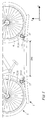
- Figure 1 shows a bicycle rack 1 for transporting a bicycle 2 on a vehicle (not shown), such as a car.
- the bicycle 2 which is schematically illustrated, has a first and a second wheel 3, 4, which in figure 1 rests on the bicycle rack 10, so that the bicycle 2 is positioned in a transport position. In the transport position, the bicycle 2 can be transported on the bicycle rack using the vehicle.
- the bicycle holder could however be adapted to hold or retain other parts of the bicycle 2, such as parts of the frame.
- the wheels 3, 4 of the bicycle are retained to the wheel holders 12, 13 using a retaining mechanism 15, partly formed by a strap element 16 and a strap element lock 17.
- a distance DW between the first and the second wheel holders 12, 13 can be changed.
- the length of the bicycle rack extends along the X axis, the height along the Y axis and a width along the Z axis, as shown in figures 1 and 4 .
- the length of the wheel holder extends along the X axis, the height along the Y axis and the width along the Z axis, as shown in figures 1 and 4 .
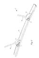
- Figure 2 shows the bicycle rack 1 without a bicycle mounted thereon.
- the strap elements 16 of the first and the second wheel holder 12, 13 are disconnected from the strap element locks 17.
- the bicycle rack 1 is, in the shown embodiment, manufactured from extruded aluminum having a substantially U-shaped cross section adapted to receive parts the wheels 3, 4 of the bicycle 2.
- the substantially U-shaped cross section is formed by groove 18 which also is adapted to cooperate with the first and the second wheel holder 12, 13 to retain the wheel holders 12, 13 to the bicycle rack 1 and to permit the wheel holders 12, 13 to slide along the length of the bicycle rack 1, i.e. along the X axis.
- the wheel holders 12, 13 can be positioned at a plurality of different positions, bicycles of different sizes can be transported using the bicycle rack 1.
- the wheels 3, 4 of the bicycle 2 rests against the bicycle rack 1 and the wheel holders 12, 13 are positioned between the rest points of the wheels 3, 4, or optionally on either side of the rest points of the wheels 3, 4.
- the wheels 3, 4 is not intended to actually rest on the wheel holders 12, 13.
- the wheel holders 12, 13 can be displaced, in this case slided, along the length of the bicycle rack 1, and thus be positioned substantially at an infinite number of different positions.
- bicycle racks having predetermined positions for wheel holders only permits a limited number of positions for the wheel holders, and thus also a limited number of different sizes of bicycles which can be transported.
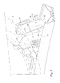
- Figure 3 shows the first wheel holder 12 in greater detail, parts of the bicycle rack 1 and the first wheel 3.
- the strap element 16 of the retaining mechanism 15 is not shown for the sake of clarity.
- the wheel holder 12 is formed by a body 20.
- the body 20 has a wheel facing side 21, an opposite bicycle rack facing side 22, a front side 23, a first and a second longitudinal side 24, 25.
- the wheel facing side 21 merges into the bicycle rack facing side 22, forming a slope like wheel facing side 21.
- a first and second flange 26, 27 extends out from the first and the second longitudinal sides 24, 25, to support a part of the first wheel 3 against a tilting motion.
- a slit 30, is arranged in the front side 23 of the body 20, i.e. in the peripheral wall of the body 20, enabling the body 20 to be temporarily deformed, or compressed.
- the slit 30 extends through the whole of the thickness of the front side 23 and has a substantially triangular form having an apex 31 and a first and a second side 32, 33.
- the body 20 can be provided with a weak point, or a weak section, to enable the body 20 to be deformed, or compressed.
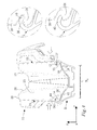
- Figure 4 shows the wheel holder 12 with a view towards the front side 23 of the body 20.
- the bicycle rack 1 is shown with a cross section.
- the U-shape of the cross section of the bicycle rack can be seen, formed by the groove 18 of the bicycle rack 1.
- the bicycle rack 1 further comprises a first and a second flange 40, 41 which extends along the length of the bicycle rack 1.
- the flanges 40, 41 provides for grip surfaces to the wheel holder 12 and enables the wheel holder 12 to be displaced along the length of the bicycle rack 1 while at the same time they provide for retaining means to retain the wheel holder 12 to the bicycle rack 1.
- the flanges 40, 41 has a hook like cross section, as is seen in figure 4 , and are adapted to cooperate with parts of the wheel holder 12.
- the body 20 of the wheel holder 12 comprises a first and a second grip portion 34, 35 adapted to cooperate in a retaining manner with the flanges 40, 41 of the bicycle rack, and thus be cooperating with the groove 18 of the bicycle rack 1.
- the first and the second grip portions 34, 35 are formed integrally with the body 20 of the wheel holder 12, but could optionally be attached to the body 20 of the wheel holder 12.
- the first and the second grip portions 34, 35 are adapted to retain the wheel holder 12 to the bicycle rack 1 by means of the intersecting flanges 40, 41 of the bicycle rack 1, and refrain it from being displaced along the length of the bicycle rack 1 using friction as primary retaining means.
- the first and the second grip portions 34, 35 are further separated by a distance DL, along the Z axis and the width of the body 20.
- the body 20 has a relaxed state, or a restricted state in which the first and the second grip portions 34, 35 are forced towards the inner surface of the groove 18 of the bicycle rack 1, so that the first and the second grip portions 34, 35 and the flanges 40, 41 are engaged.
- the user simply compress the first and second longitudinal sides 25, 25 of the body 20 towards each other, as indicated by the arrows in figure 4 .
- the first and the second grip portions 34, 35 are displaced towards each other and disengage the first and the second flange 40, 41 of the bicycle rack 1, as is seen in the enlargements of figure 4 .
- the wheel holder 12 can be slided, or displaced, along the length of the bicycle rack 1. As a user releases the body 20, the first and the second grip portions 34, 35 will return to their original position.
- the body 20 will either return to a relaxed state in which the first and the second grip portions 34, 35 engages the first and the second flange 40, 41, or to a restricted state, in which the first and the second grip portions 34, 35 are positioned adjacent the first and the second flanges 40, 41 in an abutting manner with a force, so that the first and the second grip portions 34, 35 engages the first and the second flange 40, 41.
- the body 20 can be said to operate with an expander lock function, in the sense that after being deformed or compressed, it expands back to its original size or configuration. In this case the first and the second grip portions returns to their position underneath the flanges 40, 41 of the groove 18 of the bicycle rack 1.
- the groove 18 of the bicycle rack 1 has a first and a second tilting surface 42, 43 which corresponds to the form of bicycle rack facing side 22 of the body 20.
- Tilting surfaces 38, 39 of the body 20 are tilted so that a blunt, or stub, apex-like part of the body 20 is formed towards the bicycle rack 1, as seen in figure 4 .
- the tilting surfaces 38, 39, 42, 43 of the wheel holder 12 and the groove 18 of the wheel holder 12 can be configured to impart the body 20 with an upwardly directed force component as the body 20 returns to its relaxed state, or to the restricted state.
- the tilting surfaces 38, 39 have an arc shaped form.
- Figures 5-8 show the body 20 of the wheel holder 12 with different views and in perspective.
- Figure 5 shows the slit 30 arranged on the front side 23 of the body 20 of the wheel holder 12.
- the slit 30 has an open end at the bottom of the front side 23 of the body 20 which is intended to face the bottom of the groove 18 of the bicycle rack 1 during use.
- the first and the second grip portions 34, 35, and a guiding portion 34b, are shown.
- the guiding portion 34b is adapted to improve the retaining properties of the wheel holder 12 and to guide the wheel holder 12 when being moved along the length of the bicycle rack 1.
- Parts of the first and second grip portions 34, 35 comprise a grip friendly surface, such as a pleated surface, to provide a user friendly surface during deformation and displacement of the body 20.
- the grip portions 34, 35 cooperates with tilting surfaces 34', 35' arranged on each of the first and second longitudinal sides 24, 25 of the body 20, and are arranged at an angle ⁇ with respect to the Z axis, wherein the angle ⁇ can be between 30-60°.
- figure 5 can be used for orientation.
- figure 6 shows parts of the wheel facing side 21 of the body 20. It should be noted that the wheel facing side 21 is not positioned to abut the surface of the wheel 3 of the bicycle 2.
- the retaining mechanism 15 (partly shown in figure 6 ) is tightened around the wheel 3, the retaining mechanism 15 pulls the body 20 towards the wheel 3, the force component is thus directed away from the bicycle rack 1.
- the wheel holder 12 is retained to the bicycle rack 1 by the first and the second grip portions 34, 35, as better understood from figure 3 , and thus enables the wheel holder 12 to be secured to the bicycle rack 1 as the first and the second grip portions 34, 35 cooperate with the flanges 40, 41 of the groove 18.
- the wheel holder 12 further uses the friction between the first and the second grip portions 34, 35 of the body 20 and the first and the second flange 40, 41 of the bicycle rack 1, to retain the wheel holder 12 in a desired position. A friction lock is thus provided, preventing the wheel holder 12 from being displaced along the length of the bicycle rack 1.
- Two wheel holders 12, 13 retains the bicycle 2 to the bicycle rack 1 and provides for a bicycle rack 1 which can be adapted to bicycles of different sizes.
- the wheel holder 12 thus uses the same retaining mechanism to retain and secure the bicycle with the wheel holder as to readily secure the wheel holder 12 from displacement with respect to the bicycle rack 1. In this sense, both the retaining mechanism 15 and the expander function of the body 20 are used to retain the wheel holder 12 from displacement along the length of the bicycle rack 1.
- the first and the second grip portions 34, 35 can be provided with a high friction material, such as a selected thermoplastic material, or with a corrugated, pleated surface, to increase the friction between the first and the second grip portions 34, 35 of the body 20 and the first and the second flanges 40, 41 of the bicycle rack 1, thus improving the friction lock.
- a high friction material such as a selected thermoplastic material, or with a corrugated, pleated surface
- Figure 7 shows the body 20 of the wheel holder 12 from above.
- a first and a second aperture 50, 51 is arranged at the first and the second longitudinal sides 24, 25 to permit at least one strap element 16 to be attached to the body 20 of the wheel holder 12.
- the slit 30, and the front side 23 of the body 20 has a slightly curved form, curving towards the rear of the body 20, which will improve the deformability of the body 20.
- Figure 8 shows the body 20 from beneath.
- a plurality of partition walls 55 provides for a rigid body 20.
- a second slit 30i, or an inner slit 30i, is arranged in one of the partition walls 55.
- the body 20 comprises a plurality of slits, or at least two slits 30, 30i, to enable the body 20 to be deformed, or compressed, by a user to enable the displacement of the body 20, and thus the wheel holder 12, along the length of the bicycle rack 1. Further visible is a bolt extending through the body adapted to fix the retaining mechanism 15 to the body 20.
- the body 20 can be resilient by means of the material used in the body 20, or by an attached member imparting resilient properties to the body 20.
- the body 20 can be form molded by a thermoplastic material such as polypropylene, polyethylene, polyurethane, Acrylonitrile butadiene styrene (ABS) or mixtures thereof.
- ABS Acrylonitrile butadiene styrene
- the expander mechanism of the first and the second grip portions, and the mechanism of being temporarily displaceable can be provided by other resilient means, such as a spring or elastic material positioned between the first and the second grip portion 34, 35.
- the body 20 could further be partitioned into a first and a second member, connected with hinges or the like and having a resilient member arranged to hold the first and the second grip portions separated, for example.
- the body 20 could further comprise a material or a member which improves the resilient property of the body 20.
- Elastic rubber material such as synthetic rubber or natural rubber, could be positioned inside of the body 20, e.g. between the partition walls 55, for example.
- the bicycle rack 1 can have a straight elongated form as shown in figure 1 , or have a curved elongated form.
Landscapes
- Engineering & Computer Science (AREA)
- Mechanical Engineering (AREA)
- Fittings On The Vehicle Exterior For Carrying Loads, And Devices For Holding Or Mounting Articles (AREA)
Abstract
Description
- The present invention relates to a wheel holder for a bicycle rack and a bicycle rack having at least one wheel holder. The wheel holder has a simple and user friendly expander lock function by which the position of the wheel holder can be easily displaced, and fixed, along the length of the bicycle rack permitting transportation of bicycles of varying sizes on the bicycle rack.
- Bicycle racks are used to transport bicycles on vehicles. The patent application,
WO 89/01884 - It is an object of the present invention to provide for a user friendly wheel holder which enables a user to easy displace and adjust the position of the wheel holder with respect to the bicycle rack to enable bicycles of different sizes to be transported using the bicycle rack. The object is met by a bicycle holder, such as a wheel holder, for a bicycle rack. The bicycle rack can optionally be provided with a groove for attaching the wheel holder to the bicycle rack. The wheel holder comprises a body, a first grip portion displaceably arranged to a second grip portion, the first and the second grip portions are adapted to engage a first and a second surface of the bicycle rack to retain the bicycle holder to the bicycle rack. At least one of the first and the second grip portions is/are adapted to be temporarily displaced in a direction towards the other, optionally by deforming parts of the body, wherein the first and the second grip portions are temporarily disengaged from, or removed from contact with, the first and second surfaces of the bicycle rack, enabling the position of the wheel holder to be adjusted along the length of the bicycle rack, or the bicycle holder to be removed from the bicycle rack.
- The bicycle holder is easy to displace along the length of the bicycle rack as a user can grab the bicycle holder and disengage the first and the second grip portions without releasing the bicycle holder, and thereafter move the bicycle holder using substantially one continuous motion. The bicycle holder thus has a simple and user friendly fixation function using friction as primary fixation means by which the position of the bicycle holder can be easily displaced, and fixed, along the length of the bicycle rack.
- According to an aspect, the bicycle holder comprises a retaining mechanism adapted to retain a wheel of the bicycle to the bicycle holder.
- According to an aspect, the bicycle holder is a wheel holder, and in that the part of the bicycle is a wheel.
- According to an aspect, the bicycle rack has at least one groove for attaching the bicycle holder to the bicycle rack, and in that the first and second surfaces are formed by parts of the groove. The first and second surfaces of the groove are advantageously intersecting the first and the second grip portions so that they ate positioned substantially between the grip portions of the body of the bicycle holder and the part of the bicycle received by the bicycle holder, e.g. the wheel.
- According to an aspect, the both of the first and the second grip portions are adapted to be displaced towards each other.
- According to an aspect, the body of the bicycle holder and the first and second grip portions are formed in a unitary piece of material. The body, together with the first and the second grip portions, can be form moulded for example. Optionally the first and the second grip portions can be attached to the body as separate elements.
- According to an aspect, the first and second grip portions comprise a tilting surface adapted to cooperate with a first and second surface of the bicycle rack. The tilting surfaces enable the first and the second grip portions to better engage the first and the second surface of the groove of bicycle rack as they provide for an upwardly directed force component acting on the bicycle holder to force the bicycle holder into engagement with the first and the second surfaces of the groove of bicycle rack.
- According to an aspect, the tilting surfaces of the first and the second grip portions are arranged at an angle α with respect to a axis Z. The angle α can be between 30-60°.
- According to an aspect, the body comprises at least one slit. The at least one slit of the body enables the body to be deformed so that the distance between the first and the second grip portions can be decreased. As the distance between the first and the second grip portions is decreased, the first and the second grip portions can disengage the first and the second surfaces of the groove, and enable the bicycle holder to be displaced. As the body of the bicycle holder is released, the body returns to its original form, or substantially to its original form, i.e. it might be somewhat restricted from returning to its original form by the groove of the bicycle rack.
- According to an aspect, the first and second grip portions are separated by the at least one slit. According to an aspect, the body comprises two or more slits which separates the first grip portion from the second grip portion.
- According to an aspect, the body of the bicycle holder has a front side, a first and a second longitudinal side, and at least one slit arranged in the front side of the body of the bicycle holder.
- According to an aspect, the first and the second grip portion extends out from the first and the second longitudinal sides of the body of the bicycle holder.
- According to an aspect, the body of the bicycle holder is formed by a peripheral wall defining a substantially hollow interior, and the first and the second grip portions are formed by a first and a second portion of the peripheral wall. The first and the second grip portions can be formed by parts of the first and the second longitudinal sides of the body of the bicycle holder.
- According to an aspect, the body and/or the first and second grip portions are adapted to be elastically deformable, enabling a user to temporarily deform the first and the second grip members towards each other and thus counteracting the expander lock function to adjust the position of the bicycle holder with respect to the bicycle rack, or to remove the bicycle holder from the bicycle rack.
- According to an aspect, the first and the second grip portions each comprises a grip surface adapted to cooperate with the groove of the bicycle rack. The grip surfaces of the first and the second grip portions are manufactured from a material providing a high friction surface between the grip surfaces of the first and the second grip portions and the groove of the bicycle rack.
- According to an aspect, the retaining mechanism cooperates with the first and the second grip portions so that upon activation of the retaining mechanism, the first and the second grip portions are imparted with a force component acting to increase the distance between the first and the second grip portions of the body of the bicycle holder.
- According to an aspect, the present invention also relates to a bicycle rack comprising a first and a second bicycle holder. The bicycle rack comprises a groove, and is adapted to be mounted to a vehicle. The first and the second bicycle holders are displaceably arranged in, and along, the groove of the bicycle rack.
- According to an aspect, the groove of the bicycle rack is adapted to receive a first and a second wheel of the bicycle. The first and the second wheel of the bicycle can thus use the same groove which is used for attaching the bicycle holder to the bicycle rack.
- According to an aspect, the bicycle holder comprises a body with a first and a second displaceable grip portion adapted to grip a first and a second surface of the groove of the bicycle rack to retain the bicycle holder in the groove of the bicycle rack. The body of the bicycle holder is adapted to be deformed, or compressed, to temporarily disengage from the groove of the bicycle rack, enabling the position of the bicycle holder to be adjusted with respect to the bicycle rack, or the bicycle holder to be removed from the bicycle rack. According to a second aspect of the invention, the invention relates to a bicycle holder for a bicycle rack having a groove providing a plurality of attachment positions for attaching the bicycle holder to the bicycle rack. The bicycle holder comprises a body, a first and a second displaceable grip portion adapted to grip a first and a second surface of the groove of the bicycle rack to retain the bicycle holder in the groove of the bicycle rack. The bicycle holder further comprises a retaining mechanism adapted to retain the wheel of the bicycle to the bicycle holder. Each of the grip portions comprises a friction surface adapted to cooperate with the first and the second surface of the groove of the bicycle rack, wherein when tightening the retaining mechanism, a force component directed away from the bicycle rack provides for a friction lock between first and second surface of the grip portion and the bicycle rack to prevent the bicycle holder from being displaced with respect to the bicycle rack.
- Embodiments of the present invention will be described in greater detail with reference to the accompanying figures in which;
-
figure 1 shows a bicycle mounted on a bicycle rack having a first and a second bicycle holder according to an embodiment of the present invention; -
figure 2 shows the bicycle rack offigure 1 wherein the first and the second bicycle holders are arranged to receive the wheels of the bicycle; -
figure 3 shows a bicycle holder of the bicycle rack offigure 1 in greater detail; -
figure 4 shows the bicycle holder offigure 1 with a view towards the front of the bicycle holder, and the bicycle rack in cross section; -
figure 5 shows the bicycle holder offigure 1 in perspective and with a view towards the front side of the bicycle holder; -
figure 6 shows the bicycle holder offigure 1 in perspective and with a view partly towards the wheel facing side and the front side of the bicycle holder; -
figure 7 shows the bicycle holder offigure 1 in perspective and with a view towards the wheel facing side of the bicycle holder and; -
figure 8 shows the bicycle holder offigure 1 in perspective and with a view towards the bicycle rack facing side of the bicycle holder. -
Figure 1 shows a bicycle rack 1 for transporting abicycle 2 on a vehicle (not shown), such as a car. Thebicycle 2, which is schematically illustrated, has a first and asecond wheel figure 1 rests on the bicycle rack 10, so that thebicycle 2 is positioned in a transport position. In the transport position, thebicycle 2 can be transported on the bicycle rack using the vehicle. A first and asecond bicycle holder 10, 11, in the shown embodiment adapted to hold a wheel, thus hereafter referred to only as the first and thesecond wheel holder bicycle 2, such as parts of the frame. Thewheels wheel holders strap element 16 and astrap element lock 17. To enable bicycles of different sizes to be transported, a distance DW between the first and thesecond wheel holders - For the purpose of orientation, the length of the bicycle rack extends along the X axis, the height along the Y axis and a width along the Z axis, as shown in
figures 1 and4 . Likewise, the length of the wheel holder extends along the X axis, the height along the Y axis and the width along the Z axis, as shown infigures 1 and4 . -
Figure 2 shows the bicycle rack 1 without a bicycle mounted thereon. Thestrap elements 16 of the first and thesecond wheel holder - The bicycle rack 1 is, in the shown embodiment, manufactured from extruded aluminum having a substantially U-shaped cross section adapted to receive parts the
wheels bicycle 2. The substantially U-shaped cross section is formed bygroove 18 which also is adapted to cooperate with the first and thesecond wheel holder wheel holders wheel holders wheel holders wheels bicycle 2 rests against the bicycle rack 1 and thewheel holders wheels wheels wheels wheel holders - The
wheel holders -
Figure 3 shows thefirst wheel holder 12 in greater detail, parts of the bicycle rack 1 and thefirst wheel 3. Thestrap element 16 of the retaining mechanism 15 is not shown for the sake of clarity. Thewheel holder 12 is formed by abody 20. Thebody 20 has awheel facing side 21, an opposite bicyclerack facing side 22, afront side 23, a first and a secondlongitudinal side wheel facing side 21 merges into the bicyclerack facing side 22, forming a slope likewheel facing side 21. As is also noticed, a first andsecond flange 26, 27 (only a part of thesecond flange 27 is visible infigure 3 ) extends out from the first and the secondlongitudinal sides first wheel 3 against a tilting motion. - A
slit 30, is arranged in thefront side 23 of thebody 20, i.e. in the peripheral wall of thebody 20, enabling thebody 20 to be temporarily deformed, or compressed. Theslit 30 extends through the whole of the thickness of thefront side 23 and has a substantially triangular form having an apex 31 and a first and asecond side slit 30, thebody 20 can be provided with a weak point, or a weak section, to enable thebody 20 to be deformed, or compressed. -
Figure 4 shows thewheel holder 12 with a view towards thefront side 23 of thebody 20. The bicycle rack 1 is shown with a cross section. The U-shape of the cross section of the bicycle rack can be seen, formed by thegroove 18 of the bicycle rack 1. The bicycle rack 1 further comprises a first and asecond flange flanges wheel holder 12 and enables thewheel holder 12 to be displaced along the length of the bicycle rack 1 while at the same time they provide for retaining means to retain thewheel holder 12 to the bicycle rack 1. Theflanges figure 4 , and are adapted to cooperate with parts of thewheel holder 12. - The
body 20 of thewheel holder 12 comprises a first and asecond grip portion flanges groove 18 of the bicycle rack 1. The first and thesecond grip portions body 20 of thewheel holder 12, but could optionally be attached to thebody 20 of thewheel holder 12. The first and thesecond grip portions wheel holder 12 to the bicycle rack 1 by means of the intersectingflanges second grip portions body 20. - The
body 20 has a relaxed state, or a restricted state in which the first and thesecond grip portions groove 18 of the bicycle rack 1, so that the first and thesecond grip portions flanges - If a user would like to displace the
wheel holder 12 along the length of the bicycle rack 1, i.e. along the X axis, the user simply compress the first and secondlongitudinal sides body 20 towards each other, as indicated by the arrows infigure 4 . The first and thesecond grip portions second flange figure 4 . When the first and thesecond grip portions wheel holder 12 can be slided, or displaced, along the length of the bicycle rack 1. As a user releases thebody 20, the first and thesecond grip portions body 20 will either return to a relaxed state in which the first and thesecond grip portions second flange second grip portions second flanges second grip portions second flange body 20 can be said to operate with an expander lock function, in the sense that after being deformed or compressed, it expands back to its original size or configuration. In this case the first and the second grip portions returns to their position underneath theflanges groove 18 of the bicycle rack 1. - The
groove 18 of the bicycle rack 1 has a first and asecond tilting surface 42, 43 which corresponds to the form of bicyclerack facing side 22 of thebody 20. Tilting surfaces 38, 39 of thebody 20 are tilted so that a blunt, or stub, apex-like part of thebody 20 is formed towards the bicycle rack 1, as seen infigure 4 . The tilting surfaces 38, 39, 42, 43 of thewheel holder 12 and thegroove 18 of thewheel holder 12 can be configured to impart thebody 20 with an upwardly directed force component as thebody 20 returns to its relaxed state, or to the restricted state. As is further noticed, the tilting surfaces 38, 39 have an arc shaped form. -
Figures 5-8 show thebody 20 of thewheel holder 12 with different views and in perspective.Figure 5 shows theslit 30 arranged on thefront side 23 of thebody 20 of thewheel holder 12. As is noted, theslit 30 has an open end at the bottom of thefront side 23 of thebody 20 which is intended to face the bottom of thegroove 18 of the bicycle rack 1 during use. The first and thesecond grip portions portion 34b, are shown. The guidingportion 34b is adapted to improve the retaining properties of thewheel holder 12 and to guide thewheel holder 12 when being moved along the length of the bicycle rack 1. Parts of the first andsecond grip portions body 20. Thegrip portions longitudinal sides body 20, and are arranged at an angle α with respect to the Z axis, wherein the angle α can be between 30-60°. To determine the angle α,figure 5 can be used for orientation. - With reference to
figures 3 and6; figure 6 shows parts of thewheel facing side 21 of thebody 20. It should be noted that thewheel facing side 21 is not positioned to abut the surface of thewheel 3 of thebicycle 2. When the retaining mechanism 15 (partly shown infigure 6 ) is tightened around thewheel 3, the retaining mechanism 15 pulls thebody 20 towards thewheel 3, the force component is thus directed away from the bicycle rack 1. Thewheel holder 12 is retained to the bicycle rack 1 by the first and thesecond grip portions figure 3 , and thus enables thewheel holder 12 to be secured to the bicycle rack 1 as the first and thesecond grip portions flanges groove 18. Thewheel holder 12 further uses the friction between the first and thesecond grip portions body 20 and the first and thesecond flange wheel holder 12 in a desired position. A friction lock is thus provided, preventing thewheel holder 12 from being displaced along the length of the bicycle rack 1. - Two
wheel holders bicycle 2 to the bicycle rack 1 and provides for a bicycle rack 1 which can be adapted to bicycles of different sizes. Thewheel holder 12 thus uses the same retaining mechanism to retain and secure the bicycle with the wheel holder as to readily secure thewheel holder 12 from displacement with respect to the bicycle rack 1. In this sense, both the retaining mechanism 15 and the expander function of thebody 20 are used to retain thewheel holder 12 from displacement along the length of the bicycle rack 1. - The first and the
second grip portions second grip portions body 20 and the first and thesecond flanges -
Figure 7 shows thebody 20 of thewheel holder 12 from above. A first and asecond aperture longitudinal sides strap element 16 to be attached to thebody 20 of thewheel holder 12. As is also noticed, theslit 30, and thefront side 23 of thebody 20 has a slightly curved form, curving towards the rear of thebody 20, which will improve the deformability of thebody 20.Figure 8 shows thebody 20 from beneath. A plurality ofpartition walls 55 provides for arigid body 20. Asecond slit 30i, or aninner slit 30i, is arranged in one of thepartition walls 55. According to an aspect, thebody 20 comprises a plurality of slits, or at least twoslits body 20 to be deformed, or compressed, by a user to enable the displacement of thebody 20, and thus thewheel holder 12, along the length of the bicycle rack 1. Further visible is a bolt extending through the body adapted to fix the retaining mechanism 15 to thebody 20. - The
body 20 can be resilient by means of the material used in thebody 20, or by an attached member imparting resilient properties to thebody 20. For example, thebody 20 can be form molded by a thermoplastic material such as polypropylene, polyethylene, polyurethane, Acrylonitrile butadiene styrene (ABS) or mixtures thereof. However, the expander mechanism of the first and the second grip portions, and the mechanism of being temporarily displaceable, can be provided by other resilient means, such as a spring or elastic material positioned between the first and thesecond grip portion body 20 could further be partitioned into a first and a second member, connected with hinges or the like and having a resilient member arranged to hold the first and the second grip portions separated, for example. - The
body 20 could further comprise a material or a member which improves the resilient property of thebody 20. Elastic rubber material, such as synthetic rubber or natural rubber, could be positioned inside of thebody 20, e.g. between thepartition walls 55, for example. - The bicycle rack 1 can have a straight elongated form as shown in
figure 1 , or have a curved elongated form.
Claims (16)
- A bicycle holder (10, 11) for a bicycle rack (1) adapted to retain a part of a bicycle to said bicycle rack (1), said bicycle holder (10, 11) comprising a body (20), a first grip portion (34) displaceably arranged to a second grip portion (35), said first and second grip portions (34, 35) being adapted to engage a first and a second surface of said bicycle rack (1) thereby retaining said bicycle holder (10, 11) to said bicycle rack (1) from displacement along the length of said bicycle rack (1), characterised in that
at least one of said first and said second grip portions (34, 35) of said body (20) is/are adapted to be temporarily displaced in a direction towards the other so that at least one of said first and said second grip portions (34, 35) of said body (20) is temporarily disengaged from said first and second surfaces of said bicycle rack (1), enabling the position of said bicycle holder (10, 11) to be adjusted along the length of said bicycle rack (1), or said bicycle holder (10, 11) to be removed from said bicycle rack (1). - The bicycle holder (10, 11) according to claim 1, wherein said bicycle holder is a wheel holder (10, 11), and in that said part of said bicycle (2) is a wheel (3, 4).
- The bicycle holder (10, 11) according to claim 1 or 2, wherein said bicycle rack has a groove (18) for attaching said bicycle holder (10, 11) to said bicycle rack (1), and in that said first and second surfaces are formed by parts of said groove (18).
- The bicycle holder (10, 11) according to any of the preceding claims, wherein both of said first and said second grip portions (34, 35) are adapted to be displaced towards each other.
- The bicycle holder (10, 11) according to any of the preceding claims, wherein said first and said second grip portions (34, 35) of said body (20) are adapted to be temporarily displaced in a direction towards each other by deforming parts of said body (20).
- The bicycle holder (10, 11) according to any of the preceding claims, wherein said body (20) of said bicycle holder (12, 13) and said first and said second grip portions (34, 35) are formed in a unitary piece of material.
- The bicycle holder (10, 11) according to any of the preceding claims, wherein said body (20) comprises at least one slit (30, 30i), and in that said first and second grip portions (34, 35) are separated by said at least one slit (30, 30i).
- The bicycle holder (10, 11) according to claim 7, wherein said body (20) has a wheel facing side (21), a front side (23), and a first and a second longitudinal side (24, 25), and in that said at least one slit (30, 30i) is arranged in said front side (23) of said body (20) of said wheel holder (10, 11).
- The bicycle holder (10, 11) according to any of the preceding claims, wherein said body (20) has a wheel facing side (21), a front side (23), and a first and a second longitudinal side (24, 25),wherein said first and second grip portions (34, 35) extends out from said first and second longitudinal sides (24, 25).
- The bicycle holder (10, 11) according to any of the preceding claims, wherein said body (20) of said bicycle holder (10, 11) is formed by a peripheral wall (23, 24, 25) defining a substantially hollow interior, and in that said first and second grip portions (34, 35) are formed by a first and a second portion (34, 35) of said peripheral wall (24, 25).
- The bicycle holder (10, 11) according to any of the preceding claims, wherein at least parts of said body (20) and/or said first and second grip portions (34, 35) are adapted to be elastically deformable, enabling a user to temporarily deform said first and second grip members (34, 35) towards each other.
- The bicycle holder (10, 11) according to any of the preceding claims, wherein said first and second grip portions (34, 35) each comprises a grip surface (36, 37) adapted to cooperate with said bicycle rack (1), said grip surfaces (36 ,37) of said first and second grip portions (34, 35) are manufactured from a material providing a surface with high friction between said grip surfaces (36, 37) of said first and second grip portions (34, 35) and said bicycle rack (1).
- The bicycle holder (10, 11) according to any of the preceding claims, wherein said bicycle holder comprises a retaining mechanism (15, 16) to retain said part of said bicycle (2) to said bicycler holder (10, 11), said retaining mechanism (15, 16) is adapted to cooperate with said first and second grip portions (34, 35) so that upon activation of said retaining mechanism (15, 16), said first and second grip portions (34, 35) are imparted with a force component acting to increase a distance (DG) between said first and said second grip portions (34, 35) of said body (20) of said bicycle holder (12, 13).
- A bicycle rack (1) comprising a first and a second bicycle holder (10, 11) according to any of the preceding claims, said a bicycle rack (1) comprising a groove (18), said bicycle rack (1) being adapted to be mounted to a vehicle, and in that said first and second bicycle holders (10, 11) are displaceably arranged along said groove (18) of said bicycle rack (1).
- The bicycle rack (1) according to claim 14, wherein said groove (18) of said bicycle rack (1) is adapted to receive a first and a second wheel (3, 4) of said bicycle (2).
- A bicycle holder (10, 11) for a bicycle rack (1) having a groove (18) providing a plurality of attachment positions for said bicycle holder (10, 11) to said bicycle rack (1), said bicycle holder (10, 11) comprising a body (20), said bicycle holder (10, 11) comprising a first grip portion (34) displaceably arranged to a second grip portion (35), said first and said second grip portions being adapted to grip a first and a second surface of said bicycle rack (1) to retain said bicycle holder (10, 11) to said bicycle rack (1), said bicycle holder (10, 11) comprising a retaining mechanism (15, 16) adapted to retain part (3, 4) of said bicycle (2) to said bicycle holder (10, 11),
characterised in that
each of said grip portion (34, 35) comprises a friction surface (36, 37) adapted to cooperate with said first and said second surface of said bicycle rack (1), wherein when tightening said retaining mechanism (15 ,16), said retaining mechanism (15, 16) imparts a force component to said bicycle holder (10, 11) in a direction away from said bicycle rack (1), said force component providing a friction lock between said first and second surfaces (36, 37) of said grip portion (34, 35) of said body and said bicycle rack (1), to prevent said bicycle holder (10, 11) from being displaced along the length of said bicycle rack (1).
Priority Applications (1)
| Application Number | Priority Date | Filing Date | Title |
|---|---|---|---|
| EP20110178887 EP2562048B1 (en) | 2011-08-25 | 2011-08-25 | Wheel holder for a bicycle rack and a bicycle rack having a wheel holder |
Applications Claiming Priority (1)
| Application Number | Priority Date | Filing Date | Title |
|---|---|---|---|
| EP20110178887 EP2562048B1 (en) | 2011-08-25 | 2011-08-25 | Wheel holder for a bicycle rack and a bicycle rack having a wheel holder |
Publications (2)
| Publication Number | Publication Date |
|---|---|
| EP2562048A1 true EP2562048A1 (en) | 2013-02-27 |
| EP2562048B1 EP2562048B1 (en) | 2014-02-19 |
Family
ID=44674329
Family Applications (1)
| Application Number | Title | Priority Date | Filing Date |
|---|---|---|---|
| EP20110178887 Active EP2562048B1 (en) | 2011-08-25 | 2011-08-25 | Wheel holder for a bicycle rack and a bicycle rack having a wheel holder |
Country Status (1)
| Country | Link |
|---|---|
| EP (1) | EP2562048B1 (en) |
Cited By (2)
| Publication number | Priority date | Publication date | Assignee | Title |
|---|---|---|---|---|
| WO2015185260A1 (en) * | 2014-06-05 | 2015-12-10 | Thule Sweden Ab | Wheel holder for a bicycle carrier |
| CN111959405A (en) * | 2020-07-24 | 2020-11-20 | 宁波晨帆汽车附件有限公司 | But quick assembly disassembly formula car afterbody bicycle rack subassembly |
Families Citing this family (2)
| Publication number | Priority date | Publication date | Assignee | Title |
|---|---|---|---|---|
| DE102017215959A1 (en) * | 2017-09-11 | 2019-03-14 | Atera Gmbh | Wheel shell for receiving a wheel of a two-wheeler and carrier profile arrangement of a two-wheel carrier unit with a carrier profile and with such a wheel shell |
| DE102019211471A1 (en) * | 2019-07-31 | 2021-02-04 | Atera Gmbh | Roof rack assembly for a motor vehicle |
Citations (6)
| Publication number | Priority date | Publication date | Assignee | Title |
|---|---|---|---|---|
| US4629104A (en) * | 1983-09-12 | 1986-12-16 | Societe d'Exploitation des Establissements Macroex | Bicycle rack designed for attachment to the luggage carrier of a vehicle |
| WO1989001884A1 (en) | 1987-09-02 | 1989-03-09 | J.S. Products Ab | Arrangement for a vehicle-mounted load-carrier for a cycle |
| DE19934384A1 (en) * | 1999-07-22 | 2001-01-25 | Atera Eberhard Tittel Gmbh | Bicycle carrier for mounting on motor vehicle roof has fasteners for wheels and frame mounted on relatively moveable continuously adjustable clamp parts |
| WO2001038141A1 (en) * | 1999-11-23 | 2001-05-31 | Yakima Products, Inc. | Rack assembly for a vehicle |
| US20070164065A1 (en) * | 2005-08-09 | 2007-07-19 | Davis Brian F | Adjustable bicycle wheel retainer |
| WO2009158358A1 (en) * | 2008-06-23 | 2009-12-30 | Yakima Products, Inc. | Bicycle carrier with fork mount and universal crossbar clamp |
-
2011
- 2011-08-25 EP EP20110178887 patent/EP2562048B1/en active Active
Patent Citations (6)
| Publication number | Priority date | Publication date | Assignee | Title |
|---|---|---|---|---|
| US4629104A (en) * | 1983-09-12 | 1986-12-16 | Societe d'Exploitation des Establissements Macroex | Bicycle rack designed for attachment to the luggage carrier of a vehicle |
| WO1989001884A1 (en) | 1987-09-02 | 1989-03-09 | J.S. Products Ab | Arrangement for a vehicle-mounted load-carrier for a cycle |
| DE19934384A1 (en) * | 1999-07-22 | 2001-01-25 | Atera Eberhard Tittel Gmbh | Bicycle carrier for mounting on motor vehicle roof has fasteners for wheels and frame mounted on relatively moveable continuously adjustable clamp parts |
| WO2001038141A1 (en) * | 1999-11-23 | 2001-05-31 | Yakima Products, Inc. | Rack assembly for a vehicle |
| US20070164065A1 (en) * | 2005-08-09 | 2007-07-19 | Davis Brian F | Adjustable bicycle wheel retainer |
| WO2009158358A1 (en) * | 2008-06-23 | 2009-12-30 | Yakima Products, Inc. | Bicycle carrier with fork mount and universal crossbar clamp |
Cited By (5)
| Publication number | Priority date | Publication date | Assignee | Title |
|---|---|---|---|---|
| WO2015185260A1 (en) * | 2014-06-05 | 2015-12-10 | Thule Sweden Ab | Wheel holder for a bicycle carrier |
| US9956921B2 (en) | 2014-06-05 | 2018-05-01 | Thule Sweden Ab | Wheel holder for a bicycle carrier |
| US10464499B2 (en) | 2014-06-05 | 2019-11-05 | Thule Sweden Ab | Wheel holder for a bicycle carrier |
| CN111959405A (en) * | 2020-07-24 | 2020-11-20 | 宁波晨帆汽车附件有限公司 | But quick assembly disassembly formula car afterbody bicycle rack subassembly |
| CN111959405B (en) * | 2020-07-24 | 2022-04-08 | 宁波晨帆汽车附件有限公司 | But quick assembly disassembly formula car afterbody bicycle rack subassembly |
Also Published As
| Publication number | Publication date |
|---|---|
| EP2562048B1 (en) | 2014-02-19 |
Similar Documents
| Publication | Publication Date | Title |
|---|---|---|
| US11845297B2 (en) | Rods for use with hanging file holders | |
| EP2464543B1 (en) | Vehicle retention system | |
| US8196985B2 (en) | Console assembly | |
| US8960497B2 (en) | Multi-shell dispenser for shotgun | |
| EP2562048B1 (en) | Wheel holder for a bicycle rack and a bicycle rack having a wheel holder | |
| US4133465A (en) | Adjustable vehicle article carrier | |
| MXPA05004881A (en) | Cargo-rataining bar support. | |
| US5810311A (en) | Holder for vehicle security device | |
| US20090166307A1 (en) | Storage system | |
| US10086736B1 (en) | Cup holder assembly having stabilizers | |
| RU177893U1 (en) | WHEEL HOLDER FOR A DEVICE FOR CARRIAGE OF A BICYCLE | |
| US9751448B2 (en) | Device for supporting accessories and having adjustment means and related assembly | |
| US20190308561A1 (en) | Device for mounting an object on an interior trim of a vehicle, and vehicle | |
| US9896034B2 (en) | Cargo accessory modular adapter | |
| US20150353019A1 (en) | Sliding and removable cup holder assembly for vehicle | |
| EP2689146B1 (en) | Fastening clip | |
| US20070050953A1 (en) | Anti-rattle tongue plate assembly | |
| US10569683B2 (en) | Headrest support assembly | |
| US20080264987A1 (en) | Container for use with a vehicle seat | |
| US9221423B2 (en) | Gripping device | |
| JP2005170189A (en) | Tray device | |
| US20080101884A1 (en) | Truck bed cargo organizer and methods | |
| US20170136928A1 (en) | Tray assembly | |
| JP2011046210A (en) | Article holder with attaching tool to headrest | |
| DE102009039476A1 (en) | Motor vehicle with a holding device for fixing a shopping cart bag |
Legal Events
| Date | Code | Title | Description |
|---|---|---|---|
| PUAI | Public reference made under article 153(3) epc to a published international application that has entered the european phase |
Free format text: ORIGINAL CODE: 0009012 |
|
| AK | Designated contracting states |
Kind code of ref document: A1 Designated state(s): AL AT BE BG CH CY CZ DE DK EE ES FI FR GB GR HR HU IE IS IT LI LT LU LV MC MK MT NL NO PL PT RO RS SE SI SK SM TR |
|
| AX | Request for extension of the european patent |
Extension state: BA ME |
|
| 17P | Request for examination filed |
Effective date: 20130820 |
|
| RBV | Designated contracting states (corrected) |
Designated state(s): AL AT BE BG CH CY CZ DE DK EE ES FI FR GB GR HR HU IE IS IT LI LT LU LV MC MK MT NL NO PL PT RO RS SE SI SK SM TR |
|
| RIC1 | Information provided on ipc code assigned before grant |
Ipc: B60R 9/10 20060101AFI20130904BHEP |
|
| GRAP | Despatch of communication of intention to grant a patent |
Free format text: ORIGINAL CODE: EPIDOSNIGR1 |
|
| INTG | Intention to grant announced |
Effective date: 20131021 |
|
| GRAS | Grant fee paid |
Free format text: ORIGINAL CODE: EPIDOSNIGR3 |
|
| GRAA | (expected) grant |
Free format text: ORIGINAL CODE: 0009210 |
|
| AK | Designated contracting states |
Kind code of ref document: B1 Designated state(s): AL AT BE BG CH CY CZ DE DK EE ES FI FR GB GR HR HU IE IS IT LI LT LU LV MC MK MT NL NO PL PT RO RS SE SI SK SM TR |
|
| REG | Reference to a national code |
Ref country code: GB Ref legal event code: FG4D |
|
| REG | Reference to a national code |
Ref country code: CH Ref legal event code: EP |
|
| REG | Reference to a national code |
Ref country code: AT Ref legal event code: REF Ref document number: 652740 Country of ref document: AT Kind code of ref document: T Effective date: 20140315 |
|
| REG | Reference to a national code |
Ref country code: DE Ref legal event code: R096 Ref document number: 602011004973 Country of ref document: DE Effective date: 20140403 |
|
| REG | Reference to a national code |
Ref country code: IE Ref legal event code: FG4D |
|
| REG | Reference to a national code |
Ref country code: NL Ref legal event code: T3 |
|
| REG | Reference to a national code |
Ref country code: AT Ref legal event code: MK05 Ref document number: 652740 Country of ref document: AT Kind code of ref document: T Effective date: 20140219 |
|
| REG | Reference to a national code |
Ref country code: LT Ref legal event code: MG4D |
|
| PG25 | Lapsed in a contracting state [announced via postgrant information from national office to epo] |
Ref country code: NO Free format text: LAPSE BECAUSE OF FAILURE TO SUBMIT A TRANSLATION OF THE DESCRIPTION OR TO PAY THE FEE WITHIN THE PRESCRIBED TIME-LIMIT Effective date: 20140519 Ref country code: LT Free format text: LAPSE BECAUSE OF FAILURE TO SUBMIT A TRANSLATION OF THE DESCRIPTION OR TO PAY THE FEE WITHIN THE PRESCRIBED TIME-LIMIT Effective date: 20140219 Ref country code: IS Free format text: LAPSE BECAUSE OF FAILURE TO SUBMIT A TRANSLATION OF THE DESCRIPTION OR TO PAY THE FEE WITHIN THE PRESCRIBED TIME-LIMIT Effective date: 20140619 |
|
| PG25 | Lapsed in a contracting state [announced via postgrant information from national office to epo] |
Ref country code: FI Free format text: LAPSE BECAUSE OF FAILURE TO SUBMIT A TRANSLATION OF THE DESCRIPTION OR TO PAY THE FEE WITHIN THE PRESCRIBED TIME-LIMIT Effective date: 20140219 Ref country code: AT Free format text: LAPSE BECAUSE OF FAILURE TO SUBMIT A TRANSLATION OF THE DESCRIPTION OR TO PAY THE FEE WITHIN THE PRESCRIBED TIME-LIMIT Effective date: 20140219 Ref country code: SE Free format text: LAPSE BECAUSE OF FAILURE TO SUBMIT A TRANSLATION OF THE DESCRIPTION OR TO PAY THE FEE WITHIN THE PRESCRIBED TIME-LIMIT Effective date: 20140219 Ref country code: PT Free format text: LAPSE BECAUSE OF FAILURE TO SUBMIT A TRANSLATION OF THE DESCRIPTION OR TO PAY THE FEE WITHIN THE PRESCRIBED TIME-LIMIT Effective date: 20140619 Ref country code: CY Free format text: LAPSE BECAUSE OF FAILURE TO SUBMIT A TRANSLATION OF THE DESCRIPTION OR TO PAY THE FEE WITHIN THE PRESCRIBED TIME-LIMIT Effective date: 20140219 Ref country code: ES Free format text: LAPSE BECAUSE OF FAILURE TO SUBMIT A TRANSLATION OF THE DESCRIPTION OR TO PAY THE FEE WITHIN THE PRESCRIBED TIME-LIMIT Effective date: 20140219 |
|
| PG25 | Lapsed in a contracting state [announced via postgrant information from national office to epo] |
Ref country code: LV Free format text: LAPSE BECAUSE OF FAILURE TO SUBMIT A TRANSLATION OF THE DESCRIPTION OR TO PAY THE FEE WITHIN THE PRESCRIBED TIME-LIMIT Effective date: 20140219 Ref country code: RS Free format text: LAPSE BECAUSE OF FAILURE TO SUBMIT A TRANSLATION OF THE DESCRIPTION OR TO PAY THE FEE WITHIN THE PRESCRIBED TIME-LIMIT Effective date: 20140219 Ref country code: HR Free format text: LAPSE BECAUSE OF FAILURE TO SUBMIT A TRANSLATION OF THE DESCRIPTION OR TO PAY THE FEE WITHIN THE PRESCRIBED TIME-LIMIT Effective date: 20140219 |
|
| PG25 | Lapsed in a contracting state [announced via postgrant information from national office to epo] |
Ref country code: CZ Free format text: LAPSE BECAUSE OF FAILURE TO SUBMIT A TRANSLATION OF THE DESCRIPTION OR TO PAY THE FEE WITHIN THE PRESCRIBED TIME-LIMIT Effective date: 20140219 Ref country code: RO Free format text: LAPSE BECAUSE OF FAILURE TO SUBMIT A TRANSLATION OF THE DESCRIPTION OR TO PAY THE FEE WITHIN THE PRESCRIBED TIME-LIMIT Effective date: 20140219 Ref country code: DK Free format text: LAPSE BECAUSE OF FAILURE TO SUBMIT A TRANSLATION OF THE DESCRIPTION OR TO PAY THE FEE WITHIN THE PRESCRIBED TIME-LIMIT Effective date: 20140219 Ref country code: EE Free format text: LAPSE BECAUSE OF FAILURE TO SUBMIT A TRANSLATION OF THE DESCRIPTION OR TO PAY THE FEE WITHIN THE PRESCRIBED TIME-LIMIT Effective date: 20140219 |
|
| REG | Reference to a national code |
Ref country code: DE Ref legal event code: R097 Ref document number: 602011004973 Country of ref document: DE |
|
| PG25 | Lapsed in a contracting state [announced via postgrant information from national office to epo] |
Ref country code: PL Free format text: LAPSE BECAUSE OF FAILURE TO SUBMIT A TRANSLATION OF THE DESCRIPTION OR TO PAY THE FEE WITHIN THE PRESCRIBED TIME-LIMIT Effective date: 20140219 Ref country code: SK Free format text: LAPSE BECAUSE OF FAILURE TO SUBMIT A TRANSLATION OF THE DESCRIPTION OR TO PAY THE FEE WITHIN THE PRESCRIBED TIME-LIMIT Effective date: 20140219 |
|
| PLBE | No opposition filed within time limit |
Free format text: ORIGINAL CODE: 0009261 |
|
| STAA | Information on the status of an ep patent application or granted ep patent |
Free format text: STATUS: NO OPPOSITION FILED WITHIN TIME LIMIT |
|
| 26N | No opposition filed |
Effective date: 20141120 |
|
| PG25 | Lapsed in a contracting state [announced via postgrant information from national office to epo] |
Ref country code: RS Free format text: LAPSE BECAUSE OF FAILURE TO SUBMIT A TRANSLATION OF THE DESCRIPTION OR TO PAY THE FEE WITHIN THE PRESCRIBED TIME-LIMIT Effective date: 20140903 |
|
| REG | Reference to a national code |
Ref country code: DE Ref legal event code: R097 Ref document number: 602011004973 Country of ref document: DE Effective date: 20141120 |
|
| PG25 | Lapsed in a contracting state [announced via postgrant information from national office to epo] |
Ref country code: MC Free format text: LAPSE BECAUSE OF FAILURE TO SUBMIT A TRANSLATION OF THE DESCRIPTION OR TO PAY THE FEE WITHIN THE PRESCRIBED TIME-LIMIT Effective date: 20140219 Ref country code: LU Free format text: LAPSE BECAUSE OF FAILURE TO SUBMIT A TRANSLATION OF THE DESCRIPTION OR TO PAY THE FEE WITHIN THE PRESCRIBED TIME-LIMIT Effective date: 20140825 |
|
| REG | Reference to a national code |
Ref country code: CH Ref legal event code: PL |
|
| PG25 | Lapsed in a contracting state [announced via postgrant information from national office to epo] |
Ref country code: CH Free format text: LAPSE BECAUSE OF NON-PAYMENT OF DUE FEES Effective date: 20140831 Ref country code: LI Free format text: LAPSE BECAUSE OF NON-PAYMENT OF DUE FEES Effective date: 20140831 |
|
| REG | Reference to a national code |
Ref country code: IE Ref legal event code: MM4A |
|
| PG25 | Lapsed in a contracting state [announced via postgrant information from national office to epo] |
Ref country code: SI Free format text: LAPSE BECAUSE OF FAILURE TO SUBMIT A TRANSLATION OF THE DESCRIPTION OR TO PAY THE FEE WITHIN THE PRESCRIBED TIME-LIMIT Effective date: 20140219 |
|
| PG25 | Lapsed in a contracting state [announced via postgrant information from national office to epo] |
Ref country code: IE Free format text: LAPSE BECAUSE OF NON-PAYMENT OF DUE FEES Effective date: 20140825 |
|
| GBPC | Gb: european patent ceased through non-payment of renewal fee |
Effective date: 20150825 |
|
| PG25 | Lapsed in a contracting state [announced via postgrant information from national office to epo] |
Ref country code: SM Free format text: LAPSE BECAUSE OF FAILURE TO SUBMIT A TRANSLATION OF THE DESCRIPTION OR TO PAY THE FEE WITHIN THE PRESCRIBED TIME-LIMIT Effective date: 20140219 |
|
| PG25 | Lapsed in a contracting state [announced via postgrant information from national office to epo] |
Ref country code: BG Free format text: LAPSE BECAUSE OF FAILURE TO SUBMIT A TRANSLATION OF THE DESCRIPTION OR TO PAY THE FEE WITHIN THE PRESCRIBED TIME-LIMIT Effective date: 20140219 Ref country code: MT Free format text: LAPSE BECAUSE OF FAILURE TO SUBMIT A TRANSLATION OF THE DESCRIPTION OR TO PAY THE FEE WITHIN THE PRESCRIBED TIME-LIMIT Effective date: 20140219 Ref country code: GR Free format text: LAPSE BECAUSE OF FAILURE TO SUBMIT A TRANSLATION OF THE DESCRIPTION OR TO PAY THE FEE WITHIN THE PRESCRIBED TIME-LIMIT Effective date: 20140520 |
|
| PG25 | Lapsed in a contracting state [announced via postgrant information from national office to epo] |
Ref country code: TR Free format text: LAPSE BECAUSE OF FAILURE TO SUBMIT A TRANSLATION OF THE DESCRIPTION OR TO PAY THE FEE WITHIN THE PRESCRIBED TIME-LIMIT Effective date: 20140219 Ref country code: GB Free format text: LAPSE BECAUSE OF NON-PAYMENT OF DUE FEES Effective date: 20150825 Ref country code: HU Free format text: LAPSE BECAUSE OF FAILURE TO SUBMIT A TRANSLATION OF THE DESCRIPTION OR TO PAY THE FEE WITHIN THE PRESCRIBED TIME-LIMIT; INVALID AB INITIO Effective date: 20110825 |
|
| REG | Reference to a national code |
Ref country code: FR Ref legal event code: PLFP Year of fee payment: 6 |
|
| REG | Reference to a national code |
Ref country code: FR Ref legal event code: PLFP Year of fee payment: 7 |
|
| PG25 | Lapsed in a contracting state [announced via postgrant information from national office to epo] |
Ref country code: MK Free format text: LAPSE BECAUSE OF FAILURE TO SUBMIT A TRANSLATION OF THE DESCRIPTION OR TO PAY THE FEE WITHIN THE PRESCRIBED TIME-LIMIT Effective date: 20140219 |
|
| REG | Reference to a national code |
Ref country code: FR Ref legal event code: PLFP Year of fee payment: 8 |
|
| PG25 | Lapsed in a contracting state [announced via postgrant information from national office to epo] |
Ref country code: AL Free format text: LAPSE BECAUSE OF FAILURE TO SUBMIT A TRANSLATION OF THE DESCRIPTION OR TO PAY THE FEE WITHIN THE PRESCRIBED TIME-LIMIT Effective date: 20140219 |
|
| P01 | Opt-out of the competence of the unified patent court (upc) registered |
Effective date: 20230528 |
|
| PGFP | Annual fee paid to national office [announced via postgrant information from national office to epo] |
Ref country code: NL Payment date: 20250825 Year of fee payment: 15 |
|
| PGFP | Annual fee paid to national office [announced via postgrant information from national office to epo] |
Ref country code: DE Payment date: 20250827 Year of fee payment: 15 |
|
| PGFP | Annual fee paid to national office [announced via postgrant information from national office to epo] |
Ref country code: IT Payment date: 20250825 Year of fee payment: 15 |
|
| PGFP | Annual fee paid to national office [announced via postgrant information from national office to epo] |
Ref country code: BE Payment date: 20250825 Year of fee payment: 15 |
|
| PGFP | Annual fee paid to national office [announced via postgrant information from national office to epo] |
Ref country code: FR Payment date: 20250825 Year of fee payment: 15 |