EP2561991A1 - Thermal head, method of producing thermal head, and thermal printer - Google Patents
Thermal head, method of producing thermal head, and thermal printer Download PDFInfo
- Publication number
- EP2561991A1 EP2561991A1 EP12180200A EP12180200A EP2561991A1 EP 2561991 A1 EP2561991 A1 EP 2561991A1 EP 12180200 A EP12180200 A EP 12180200A EP 12180200 A EP12180200 A EP 12180200A EP 2561991 A1 EP2561991 A1 EP 2561991A1
- Authority
- EP
- European Patent Office
- Prior art keywords
- heat
- active component
- layer
- thermally active
- thermal head
- Prior art date
- Legal status (The legal status is an assumption and is not a legal conclusion. Google has not performed a legal analysis and makes no representation as to the accuracy of the status listed.)
- Withdrawn
Links
Images




Classifications
-
- B—PERFORMING OPERATIONS; TRANSPORTING
- B41—PRINTING; LINING MACHINES; TYPEWRITERS; STAMPS
- B41J—TYPEWRITERS; SELECTIVE PRINTING MECHANISMS, i.e. MECHANISMS PRINTING OTHERWISE THAN FROM A FORME; CORRECTION OF TYPOGRAPHICAL ERRORS
- B41J2/00—Typewriters or selective printing mechanisms characterised by the printing or marking process for which they are designed
- B41J2/315—Typewriters or selective printing mechanisms characterised by the printing or marking process for which they are designed characterised by selective application of heat to a heat sensitive printing or impression-transfer material
- B41J2/32—Typewriters or selective printing mechanisms characterised by the printing or marking process for which they are designed characterised by selective application of heat to a heat sensitive printing or impression-transfer material using thermal heads
- B41J2/335—Structure of thermal heads
- B41J2/33505—Constructional details
- B41J2/3353—Protective layers
-
- B—PERFORMING OPERATIONS; TRANSPORTING
- B41—PRINTING; LINING MACHINES; TYPEWRITERS; STAMPS
- B41J—TYPEWRITERS; SELECTIVE PRINTING MECHANISMS, i.e. MECHANISMS PRINTING OTHERWISE THAN FROM A FORME; CORRECTION OF TYPOGRAPHICAL ERRORS
- B41J2/00—Typewriters or selective printing mechanisms characterised by the printing or marking process for which they are designed
- B41J2/315—Typewriters or selective printing mechanisms characterised by the printing or marking process for which they are designed characterised by selective application of heat to a heat sensitive printing or impression-transfer material
- B41J2/32—Typewriters or selective printing mechanisms characterised by the printing or marking process for which they are designed characterised by selective application of heat to a heat sensitive printing or impression-transfer material using thermal heads
- B41J2/335—Structure of thermal heads
- B41J2/3354—Structure of thermal heads characterised by geometry
-
- B—PERFORMING OPERATIONS; TRANSPORTING
- B41—PRINTING; LINING MACHINES; TYPEWRITERS; STAMPS
- B41J—TYPEWRITERS; SELECTIVE PRINTING MECHANISMS, i.e. MECHANISMS PRINTING OTHERWISE THAN FROM A FORME; CORRECTION OF TYPOGRAPHICAL ERRORS
- B41J2/00—Typewriters or selective printing mechanisms characterised by the printing or marking process for which they are designed
- B41J2/315—Typewriters or selective printing mechanisms characterised by the printing or marking process for which they are designed characterised by selective application of heat to a heat sensitive printing or impression-transfer material
- B41J2/32—Typewriters or selective printing mechanisms characterised by the printing or marking process for which they are designed characterised by selective application of heat to a heat sensitive printing or impression-transfer material using thermal heads
- B41J2/335—Structure of thermal heads
- B41J2/33555—Structure of thermal heads characterised by type
- B41J2/3357—Surface type resistors
-
- B—PERFORMING OPERATIONS; TRANSPORTING
- B41—PRINTING; LINING MACHINES; TYPEWRITERS; STAMPS
- B41J—TYPEWRITERS; SELECTIVE PRINTING MECHANISMS, i.e. MECHANISMS PRINTING OTHERWISE THAN FROM A FORME; CORRECTION OF TYPOGRAPHICAL ERRORS
- B41J2/00—Typewriters or selective printing mechanisms characterised by the printing or marking process for which they are designed
- B41J2/315—Typewriters or selective printing mechanisms characterised by the printing or marking process for which they are designed characterised by selective application of heat to a heat sensitive printing or impression-transfer material
- B41J2/32—Typewriters or selective printing mechanisms characterised by the printing or marking process for which they are designed characterised by selective application of heat to a heat sensitive printing or impression-transfer material using thermal heads
- B41J2/335—Structure of thermal heads
- B41J2/3359—Manufacturing processes
Definitions
- the present invention relates to a thermal head, a method of producing a thermal head, and a thermal printer including a thermal head.
- an adhesive label has been used, for example, as a food POS label, a distribution/transport label, a medical label, a baggage tag, or a display label for bottles and cans.
- the adhesive label has a pressure-sensitive adhesion surface provided with a pressure-sensitive adhesive layer on a reverse side of a recording surface (printing surface).
- the adhesive label is stored with release paper (separator) provisionally attached to the pressure-sensitive adhesion surface and is used after the separator is detached from the pressure-sensitive adhesion surface.
- release paper separator
- thermosensitive pressure-sensitive adhesive label that does not use a separator.
- the thermosensitive pressure-sensitive adhesive label is provided with a thermosensitive pressure-sensitive adhesive layer having no pressure-sensitive adhesiveness at room temperature on a reverse surface of a recording surface of a thermosensitive coloring type, and the thermosensitive pressure-sensitive adhesive layer expresses pressure-sensitive adhesive strength when heated.
- thermosensitive pressure-sensitive adhesive label As a printer for printing and issuing the above-mentioned type of thermosensitive pressure-sensitive adhesive label, a thermal printer including a thermal head that uses a plurality of heat-generating elements as a heat source is known.
- a thermosensitive pressure-sensitive adhesive label is conveyed while being interposed between a platen roller and a thermal head, and the thermal head is brought into sliding contact with a thermosensitive pressure-sensitive adhesive layer of the traveling thermosensitive pressure-sensitive adhesive label to heat the thermosensitive pressure-sensitive adhesive layer, to thereby allow the layer to express pressure-sensitive adhesive strength.
- thermosensitive pressure-sensitive adhesive or a denatured substance of a thermosensitive pressure-sensitive adhesive (substance changed chemically with heat or carbonized substance) adheres to the surface of the thermal head.
- the thermally active component adhering to the surface of the thermal head causes resistance to the conveyance of the thermosensitive pressure-sensitive adhesive label, which may cause suspension or bending of a traveling thermosensitive pressure-sensitive adhesive label, or a conveyance failure such as paper jam. Further, the thermally active component adhering to the surface of the thermal head hinders the transmission of heat, and hence, a heat conduction efficiency may be degraded.
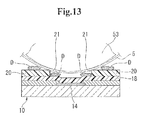
- FIG. 13 is an explanatory diagram of a conventional thermal head 10 for expressing pressure-sensitive adhesive strength.
- the thermal head 10 for expressing pressure-sensitive adhesive strength has been proposed in which a heat-generating element 14 is covered with a protective layer 18, and two lines of thermally active component adhesion preventing layers 20 are provided on an upper surface of the protective layer 18 to be substantially in parallel to each other so as to sandwich a region right above the heat-generating element 14 (see, for example, Japanese Patent Application Laid-open No. 2004-50507 ).
- a thermally active component D adheres to a thermosensitive pressure-sensitive adhesive label 5 to be swept out onto the thermally active component adhesion preventing layer 20 from the region right above the heat-generating element 14, and hence, the thermally active component D can be prevented from remaining in the region right above the heat-generating element 14.
- the thermal head 10 for expressing pressure-sensitive adhesive strength described in Japanese Patent Application Laid-open No. 2004-50507 still has the following problems.
- the thermally active component adhesion preventing layers 20 are formed in two rows with the region right above the heat-generating element 14 opened. Therefore, a step 21 provided by the thermally active component adhesion preventing layer 20 is formed on each of an upstream side and a downstream side of the heat-generating element 14.
- thermosensitive pressure-sensitive adhesive label 5 When the thermosensitive pressure-sensitive adhesive label 5 is conveyed by a platen roller 53, the thermosensitive pressure-sensitive adhesive label 5 comes into sliding contact with the step 21 of the thermally active component adhesion preventing layer 20. Therefore, the thermally active component D adhering to the thermosensitive pressure-sensitive adhesive label 5 is caught on the step 21 to remain in a gap between the platen roller 53 and the protective layer 18 and may adhere to the region above the heat-generating element 14 and the periphery of the heat-generating element 14.
- a thermal head including a heat-generating element on a principal plane of a substrate, the thermal head being configured to heat a thermosensitive layer of a thermosensitive label conveyed while being interposed between the heat-generating element and a platen roller opposed to the heat-generating element, in which the principal plane of the substrate has a thermally active component adhesion preventing layer formed thereon, which comes into sliding contact with the thermosensitive layer and is formed at least on an upstream side and a downstream side of the heat-generating element in a conveyance direction of the thermosensitive label, and in which a surface of the thermally active component adhesion preventing layer is formed in a shape following an outer circumferential surface of the platen roller.
- the surface of the thermally active component adhesion preventing layer is formed along the outer circumferential surface of the platen roller without any step. Therefore, when the thermosensitive label is conveyed while being interposed between the platen roller and the heat-generating element, the thermosensitive layer of the thermosensitive label and the surface of the thermally active component adhesion preventing layer can come into surface contact with each other.
- the thermally active component adhesion preventing layer has a property of preventing the adhesion of the thermally active component.
- thermosensitive layer of the thermosensitive label is conveyed to the downstream side of the heat-generating element to be removed from the region right above and the periphery of the heat-generating element without being caught on the surface of the thermally active component adhesion preventing layer or remaining in a gap between the platen roller and the thermally active component adhesion preventing layer.
- the thermally active component can be prevented from remaining and from adhering to the region right above the heat-generating element and the periphery of the heat-generating element.
- the thermally active component adhesion preventing layer is formed continuously between the upstream side and the downstream side of the heat-generating element in the conveyance direction, and in which the surface of the thermally active component adhesion preventing layer is formed in the shape following the outer circumferential surface of the platen roller between the upstream side and the downstream side of the heat-generating element in the conveyance direction.
- the thermally active component adhesion preventing layer is formed so as to cover the heat-generating element. Therefore, the thermally active component can be reliably prevented from adhering to the surface of the thermally active component adhesion preventing layer corresponding to the heat-generating element.
- the surface of the thermally active component adhesion preventing layer is formed along an outer circumferential shape of the platen roller between the upstream side and the downstream side of the heat-generating element in the conveyance direction of the thermosensitive label, and hence, the thermosensitive layer of the thermosensitive label and the thermally active component adhesion preventing layer are brought into surface contact with each other in a wide range without any step from the upstream side to the downstream side.
- the thermally active component can be conveyed to the downstream side of the heat-generating element to be removed reliably without being caught on the surface of the thermally active component adhesion preventing layer.
- a gap is not formed between the platen roller and the thermally active component adhesion preventing layer, and hence, the thermally active component does not remain in a gap between the platen roller and the thermally active component adhesion preventing layer.
- the thermally active component can be reliably prevented from remaining and from adhering to the region above the heat-generating element and the periphery of the heat-generating element.
- the surface of the thermally active component adhesion preventing layer is formed along the outer circumferential shape of the platen roller, and hence, the surface is formed substantially in an arc shape between the upstream side and the downstream side of the heat-generating element in the conveyance direction of the thermosensitive label. Therefore, the portion of the thermally active component adhesion preventing layer corresponding to the heat-generating element is formed thinner compared with portions corresponding to the upstream side and the downstream side in the conveyance direction of the thermosensitive label. Thus, a decrease in a heat conduction efficiency is suppressed when heat is transmitted from the heat-generating element to the thermosensitive layer via the thermally active component adhesion preventing layer.
- the thermally active component adhesion preventing layer contains one of a silicone-based resin and a fluorine-based resin as a main component.
- the thermally active component adhesion preventing layer that has low surface energy and is excellent in water repellency and oil repellency can be formed.
- the thermally active component adhering to the thermosensitive layer of the thermosensitive label can be conveyed to the downstream side of the heat-generating element together with the conveyance of the thermosensitive label to be removed reliably without being caught on the surface of the thermally active component adhesion preventing layer or remaining. Therefore, the thermally active component can be prevented from adhering to the region above the heat-generating element and the periphery of the heat-generating element.
- the thermally active component adhesion preventing layer contains, as a main component, a material obtained by adding powder of one of an oxide, a nitride, and an oxynitride of one of silicon, a silicon-based alloy, titanium, a titanium-based alloy, tantalum, and a tantalum-based alloy to a fluorine-based resin.
- the abrasion resistance of the thermally active component adhesion preventing layer can be enhanced while water repellency and oil repellency are kept.
- a thermal head can be provided, which is capable of preventing the thermally active component from adhering to the region above the heat-generating element and the periphery of the heat-generating element and which is excellent in abrasion resistance.
- the thermally active component adhesion preventing layer contains, as a main component, a material obtained by adding one of metal and carbon to a fluorine-based resin.
- the thermally active component adhesion preventing layer is allowed to have conductivity while keeping water repellency and oil repellency by adding metal or carbon to form the thermally active component adhesion preventing layer.
- static electricity generated when the thermosensitive label and the thermally active component adhesion preventing layer come into sliding contact with each other can be discharged from the thermally active component adhesion preventing layer.
- the thermally active component can be prevented from adhering to the region above the heat-generating element and the periphery of the heat-generating element due to static electricity, and electrostatic breakdown of an electronic element such as the heat-generating element can be prevented.
- thermosensitive label is a thermosensitive pressure-sensitive adhesive label
- thermosensitive layer is a thermosensitive pressure-sensitive adhesive layer for expressing pressure-sensitive adhesive strength by heating.
- the thermally active component adhesion preventing layer has a property of preventing the adhesion of the thermally active component. Therefore, even a thermally active component having pressure-sensitive adhesiveness is conveyed to the downstream side of the heat-generating element together with the movement of the thermosensitive label to be removed without being caught on the surface of the thermally active component adhesion preventing layer.
- the thermally active component adhesion preventing layer is preferred for a thermosensitive pressure-sensitive adhesive label provided with a thermosensitive pressure-sensitive adhesive layer that expresses pressure-sensitive adhesive strength by heating.
- a method of producing a thermal head includes a heat-generating element on a principal plane of a substrate, the thermal head being configured to heat a thermosensitive layer of a thermosensitive label conveyed while being interposed between the heat-generating element and a platen roller opposed to the heat-generating element, the method including forming a thermally active component adhesion preventing layer that comes into sliding contact with the thermosensitive layer on the principal plane of the substrate at least on an upstream side and a downstream side of the heat-generating element in a conveyance direction of the thermosensitive label, in which the forming a thermally active component adhesion preventing layer includes: forming a base layer of the thermally active component adhesion preventing layer on the principal plane of the substrate so that the base layer overlaps the heat-generating element; and after forming the base layer, forming a surface along an outer circumferential surface of the platen roller by processing the base layer at least on the upstream side and the downstream side of the heat-generating element in the conveyance
- the thermally active component adhesion preventing layer it is necessary to form a base layer of a thermally active component adhesion preventing layer by masking the positions corresponding to the heat-generating elements so that the thermally active component adhesion preventing layer is not formed in a region right above the heat-generating element, for the purpose of preventing a decrease in a heat conduction efficiency.
- the mask is formed by, for example, photolithography, and hence, the step is very complicated.
- the surface processing is performed along the outer circumferential surface of the platen roller. Therefore, it is not necessary to mask the positions corresponding to the heat-generating elements.
- the thermally active component adhesion preventing layer having the surface along the outer circumferential surface of the platen roller can be formed easily.
- a material for forming the thermally active component adhesion preventing layer is limited to, for example, a silicone-based resin.
- the thick base layer is processed to form the surface of the thermally active component adhesion preventing layer. Therefore, the center portion of the thermally active component adhesion preventing layer can be formed to a desired thickness by adjusting a processing amount.
- the base layer before processing can be formed thick, and hence, the material for forming the thermally active component adhesion preventing layer is not limited, and a thermal head having a desired heat conduction efficiency can be formed.
- the forming a surface includes bringing an outer circumferential surface of a polishing roller having a diameter substantially equal to a diameter of the platen roller into contact with the base layer to polish the base layer.
- the outer circumferential surface of the polishing roller has a diameter substantially equal to that of the platen roller. Therefore, the surface of the thermally active component adhesion preventing layer having a shape following the outer circumferential surface of the platen roller can be formed easily with good precision merely by polishing the base layer with the polishing roller.
- the polishing amount can be adjusted easily, and hence, the base layer covering the heat-generating elements can be formed to a desired thickness and the heat-generating elements can be exposed from the base layer.
- a thermal head having a desired heat conduction efficiency can be formed.
- the forming a surface includes bringing a side surface of a disk grinder into contact with the base layer to polish the base layer, and the side surface of the disk grinder is formed on a curved surface having a radius of curvature substantially equal to a radius of curvature of the outer circumferential surface of the platen roller.
- the side surface of the disk grinder is formed on the curved surface having a radius of curvature substantially equal to that of the platen roller. Therefore, the surface of the thermally active component adhesion preventing layer having a shape following the outer circumferential surface of the platen roller can be formed easily with good precision merely by polishing the base layer with the disk grinder. Further, in the same way as described above, the polishing amount can be adjusted easily, and hence, a thermal head having a desired heat conduction efficiency can be formed.
- the forming a surface includes pressing an outer circumferential surface of a die against the base layer, and the outer circumferential surface of the die is formed on a curved surface having a radius of curvature substantially equal to a radius of curvature of the outer circumferential surface of the platen roller.
- the outer circumferential surface of the die is formed on the curved surface having a radius of curvature substantially equal to that of the platen roller. Therefore, the surface of the thermally active component adhesion preventing layer having a shape following the outer circumferential surface of the platen roller can be formed easily with good precision merely by pressing the outer circumferential surface of the die against the base layer.
- the base layer covering the heat-generating elements can be formed to a desired thickness by adjusting the pressure force of the die. Therefore, a thermal head having a desired heat conduction efficiency can be formed.
- the forming a surface includes conveying a polishing sheet with the platen roller and bringing the polishing sheet into sliding contact with the base layer to polish the base layer.
- the surface of the thermally active component adhesion preventing layer having a shape following the outer circumferential surface of the platen roller can be formed easily with good precision without using a tool. Further, the polishing amount can be adjusted easily, and hence, the base layer covering the heat-generating elements can be formed to a desired thickness and the heat-generating elements can be exposed from the base layer. Thus, a thermal head having a desired heat conduction efficiency can be formed.
- a thermal printer of the present invention includes the above-mentioned thermal head.
- a high performance thermal printer having a high heat conduction efficiency is obtained without any conveyance defects of a thermosensitive label by providing a thermal head capable of preventing a thermally active component from adhering to a region above a heat-generating element and the periphery of the heat-generating element.
- the surface of the thermally active component adhesion preventing layer is formed along the outer circumferential surface of the platen roller without any step. Therefore, when the thermosensitive label is conveyed while being interposed between the platen roller and the heat-generating element, the thermosensitive layer of the thermosensitive label and the surface of the thermally active component adhesion preventing layer can come into surface contact with each other.
- the thermally active component adhesion preventing layer has a property of preventing the adhesion of the thermally active component.
- thermosensitive layer of the thermosensitive label is conveyed to the downstream side of the heat-generating element to be removed from the region right above and the periphery of the heat-generating element without being caught on the surface of the thermally active component adhesion preventing layer or remaining in a gap between the platen roller and the thermally active component adhesion preventing layer.
- the thermally active component can be prevented from remaining in and from adhering to the region above the heat-generating element and the periphery of the heat-generating element.
- FIG. 1 is a schematic view of a thermal printer 1.
- a thermal printer 1 prints a barcode, a price, or the like on one surface of a thermosensitive pressure-sensitive adhesive label 5 (thermosensitive label) unrolled from a sheet roll R and conveyed, cuts the thermosensitive pressure-sensitive adhesive label 5 to a desired length, causes the other surface of the thermosensitive pressure-sensitive adhesive label 5 to express pressure-sensitive adhesive strength, and issues the label.
- the conveyance direction of the thermosensitive pressure-sensitive adhesive label 5 is defined as S.
- the conveyance direction S is directed from the right side to the left side in FIG. 1 .
- the right side is defined as an upstream side of the conveyance direction S
- the left side is defined as a downstream side of the conveyance direction S.
- the upstream side of the conveyance direction S is sometimes merely referred to as an upstream side
- the downstream side of the conveyance direction S is sometimes merely referred to as a downstream side.
- the inside surface of the sheet roll R corresponds to the one surface of the thermosensitive pressure-sensitive adhesive label 5, and a thermosensitive coloring layer 5a that is discolored by heating to be printed is formed on the one surface.
- the outside surface of the sheet roll R corresponds to the other surface of the thermosensitive pressure-sensitive adhesive label 5, and a thermosensitive pressure-sensitive adhesive layer 5b (thermosensitive layer) that is heated to express pressure-sensitive adhesive strength is formed on the other surface.
- the thermal printer 1 includes a printing unit 2 for performing printing with respect to the thermosensitive coloring layer 5a by heating the thermosensitive coloring layer 5a from the one surface side (upper side in FIG. 1 ) of the thermosensitive pressure-sensitive adhesive label 5 to be conveyed, a cutter unit 3 for cutting the thermosensitive pressure-sensitive adhesive label 5 unrolled from the sheet roll R to a desired length, and a pressure-sensitive adhesive strength expressing unit 4 for causing the thermosensitive pressure-sensitive adhesive layer 5b to express pressure-sensitive adhesive strength by heating the thermosensitive pressure-sensitive adhesive layer 5b from the other surface side (lower side in FIG. 1 ) of the thermosensitive pressure-sensitive adhesive label 5.
- a thermal head according to the present invention is a thermal head 10 for expressing pressure-sensitive adhesive strength described later, and constitutes the pressure-sensitive adhesive strength expressing unit 4.
- the printing unit 2 is placed on the downstream side of the sheet roll R and includes a first platen roller 51 and a printing thermal head 8.
- the printing thermal head 8 has a plurality of heat-generating elements (not shown) and is placed so as to face the thermosensitive coloring layer 5a of the thermosensitive pressure-sensitive adhesive label 5. Further, the first platen roller 51 is placed on an opposite side of the printing thermal head 8 with the thermosensitive pressure-sensitive adhesive label 5 interposed therebetween.
- the printing thermal head 8 is biased to the first platen roller 51 side by a spring or the like (not shown). Therefore, the thermosensitive pressure-sensitive adhesive label 5 is interposed elastically between the printing thermal head 8 and the first platen roller 51.
- the printing thermal head 8 is supplied with power from a power source (not shown)
- the plurality of heat-generating elements generate heat
- the thermosensitive coloring layer 5a of the thermosensitive pressure-sensitive adhesive label 5 is heated to be printed with letters, graphics, and the like.
- the first platen roller 51 is rotated by a drive source (not shown)
- the thermosensitive pressure-sensitive adhesive label 5 is conveyed while the thermosensitive coloring layer 5a and the printing thermal head 8 are in sliding contact with each other.
- the cutter unit 3 is placed on the downstream side of the printing unit 2 and has a movable blade 55 and a fixed blade 57 on either side of the thermosensitive pressure-sensitive adhesive label 5.
- the movable blade 55 is capable of reciprocating and sliding against the fixed blade 57 and cuts the printed thermosensitive pressure-sensitive adhesive label 5 to a desired length.
- the pressure-sensitive adhesive strength expressing unit 4 is placed on the downstream side of the cutter unit 3 and includes a second platen roller 53 (corresponding to a "platen roller” in the claims) and the thermal head 10 for expressing pressure-sensitive adhesive strength (corresponding to a "thermal head” in the claims).
- the thermal head 10 for expressing pressure-sensitive adhesive strength includes a plurality of heat-generating elements 14 (see FIG. 2 ) as described later and is placed so as to face the thermosensitive pressure-sensitive adhesive layer 5b of the thermosensitive pressure-sensitive adhesive label 5.
- the second platen roller 53 is placed on the opposite side of the thermal head 10 for expressing pressure-sensitive adhesive strength with the thermosensitive pressure-sensitive adhesive label 5 interposed therebetween.
- thermosensitive pressure-sensitive adhesive label 5 is interposed elastically between the thermal head 10 for expressing pressure-sensitive adhesive strength and the second platen roller 53.
- thermosensitive pressure-sensitive adhesive label 5 is supplied with power from a power source (not shown)
- the plurality of heat-generating elements 14 generate heat
- the thermosensitive pressure-sensitive adhesive layer 5b of the thermosensitive pressure-sensitive adhesive label 5 is heated to express pressure-sensitive adhesive strength.
- the second platen roller 53 is rotated by a drive source (not shown)
- the thermosensitive pressure-sensitive adhesive label 5 is conveyed while the thermosensitive pressure-sensitive adhesive layer 5b and the thermal head 10 for expressing pressure-sensitive adhesive strength are in sliding contact with each other.
- thermal head 10 for expressing pressure-sensitive adhesive strength of this embodiment is described.
- FIG. 2 is a plan view of the thermal head 10 for expressing pressure-sensitive adhesive strength.
- FIG. 3 is a cross-sectional perspective view of the thermal head 10 for expressing pressure-sensitive adhesive strength.
- the protective layer 18 and a thermally active component adhesion preventing layer 20 are omitted.
- the conveyance direction S of the thermosensitive pressure-sensitive adhesive label 5 is directed from the right side to the left side.
- the right side is defined as an upstream side and the left side is defined as a downstream side.
- the width direction of the thermosensitive pressure-sensitive adhesive label 5 to be conveyed is defined as W
- the thickness direction of the thermal head 10 for expressing pressure-sensitive adhesive strength orthogonal to the conveyance direction S and the width direction W is defined as H.
- the thermal head 10 for expressing pressure-sensitive adhesive strength includes a substrate 12, the plurality of heat-generating elements 14 formed on a principal plane 12a of the substrate 12, and electrodes 16 and 17 connected to the heat-generating elements 14. Further, as illustrated in FIG. 3 , the protective layer 18 covering the heat-generating elements 14 and the electrodes 16, 17, and the thermally active component adhesion preventing layer 20 covering the protective layer 18 are formed on the principal plane 12a of the substrate 12.
- the substrate 12 is shaped to be substantially rectangular in plan view, having a short side in the conveyance direction S of the thermosensitive pressure-sensitive adhesive label 5 (see FIG. 1 ) and a long side in the width direction W of the thermosensitive pressure-sensitive adhesive label 5 (see FIG. 1 ).
- the substrate 12 is formed of, for example, ceramics and has an insulating property.
- the heat-generating element 14 is shaped to be substantially rectangular in a planar view.
- the heat-generating element 14 is a heat-generating resistive element for generating heat when supplied with a current.
- the heat-generating elements 14 are arranged at a substantially equal interval in the width direction W substantially at the center of the principal plane 12a of the substrate 12 in the conveyance direction S.
- the heat-generating element 14 is formed of, for example, a heat-generating resistive material such as tantalum (Ta) and silicon oxide (SiO 2 ).
- the electrodes 16 and 17 connected to the heat-generating elements 14 are formed on the principal plane 12a of the substrate 12.
- the electrodes 16 and 17 are formed of metal having a high electric conductivity such as gold (Au), copper (Cu), or aluminum (Al).
- the electrodes 16 and 17 are respectively formed so as to cover ends of the heat-generating elements 14 in the conveyance direction S and connected electrically to the heat-generating elements 14. Further, the electrodes 16 and 17 are electrically connected to a power source (not shown) in such a manner that the heat-generating elements 14 are supplied with a current from the power source through the electrodes 16 and 17.
- the protective layer 18 is formed so as to cover the heat-generating elements 14 and the electrodes 16 and 17 on the principal plane 12a of the substrate 12.
- the protective layer 18 prevents the surfaces of the heat-generating elements 14 and the electrodes 16 and 17 from being oxidized. Further, the protective layer 18 prevents the thermosensitive pressure-sensitive adhesive label 5 and the heat-generating elements 14 and the electrodes 16 and 17 from coming into sliding contact with each other to be worn away, when the thermosensitive pressure-sensitive adhesive label 5 is conveyed.
- the protective layer 18 is formed of, for example, hard ceramics such as Si-O-N or Si-Al-O-N.
- the thickness of the protective layer 18 is formed so as to be substantially uniform on the heat-generating elements 14 and the electrodes 16 and 17. As described above, only the ends of the heat-generating elements 14 in the conveyance direction S are covered with the electrodes 16 and 17. Therefore, when the protective layer 18 having substantially uniform thickness is formed on the heat-generating elements 14 and the electrodes 16 and 17, a concave 18a having a different height in the thickness direction H, compared with those of the upstream side and the downstream side of the heat-generating elements 14, is formed in a region covering the surface of the heat-generating elements 14 between the electrodes 16 and 17.
- FIG. 4 is a cross-sectional side view taken along the line A-A of FIG. 2 .
- the thermosensitive pressure-sensitive adhesive label 5 and the second platen roller 53 are indicated by alternate long and two short dashes lines.
- the thermally active component adhesion preventing layer 20 is formed on the uppermost surface of the principal plane 12a of the substrate 12.
- the thermally active component adhesion preventing layer 20 is formed continuously between the upstream side and the downstream side of the conveyance direction S across the heat-generating elements 14 so as to cover the underlying protective layer 18.
- the thermally active component adhesion preventing layer 20 includes at least an upstream portion 20a formed on the upstream side in the conveyance direction S across the heat-generating elements 14 and a downstream portion 20b formed on the downstream side in the conveyance direction S across the heat-generating elements 14.
- the thermally active component adhesion preventing layer 20 of this embodiment includes the upstream portion 20a covering the electrode 17 on the upstream side, the downstream portion 20b covering the electrode 16 on the downstream side, and a center portion 20c covering the heat-generating elements 14 between the upstream portion 20a and the downstream portion 20b.
- the upstream portion 20a, the downstream portion 20b, and the center portion 20c are formed continuously.
- the thermally active component adhesion preventing layer 20 is in sliding contact with the thermosensitive pressure-sensitive adhesive layer 5b, when the thermosensitive pressure-sensitive adhesive label 5 is conveyed while being interposed between the heat-generating elements 14 and the second platen roller 53.
- the thermally active component adhesion preventing layer 20 is formed of a material that has low surface energy and is excellent in water repellency and oil repellency, for example, a silicon-based resin or a fluorine-based resin.
- the thermally active component adhesion preventing layer 20 has a property of preventing the adhesion of the thermally active component D of the thermosensitive pressure-sensitive adhesive layer 5b.
- the thermally active component adhesion preventing layer 20 may be formed of a material obtained by adding powder of an oxide, a nitride, or an oxynitride of silicon, a silicon-based alloy, titanium, a titanium-based alloy, tantalum, or a tantalum-based alloy to a fluorine-based resin. This enables the formation of the thermally active component adhesion preventing layer 20 that has low surface energy, keeps property excellent in water repellency and oil repellency, and is excellent in abrasion resistance.
- the thermally active component adhesion preventing layer 20 may be formed of a material obtained by adding metal or carbon to a fluorine-based resin. This allows the thermally active component adhesion preventing layer 20 to have conductivity while having low surface energy and keeping property excellent in water repellency and oil repellency. Then, even when the thermosensitive pressure-sensitive adhesive layer 5b and the thermally active component adhesion preventing layer 20 come into sliding contact with each other to generate static electricity when the thermosensitive pressure-sensitive adhesive label 5 is conveyed, static electricity can be discharged from the thermally active component adhesion preventing layer 20 gradually. Accordingly, electrostatic breakdown of electronic elements such as the heat-generating elements 14 can be prevented.
- the hardness of the thermally active component adhesion preventing layer 20 be set, for example, in a range of 2B to 5B in terms of pencil hardness, although depending upon the kind of the thermosensitive pressure-sensitive adhesive label 5.
- the hardness of the thermally active component adhesion preventing layer 20 can be adjusted by, for example, the kind and addition amount of an additive to a material.
- the thermally active component adhesion preventing layer 20 may be formed through an intermediate film (primer) that is formed of a silane coupling agent or the like and has excellent adhesion. Further, the thermally active component adhesion preventing layer 20 may be formed by solving the problem of surface roughness of the protective layer 18 by mechanical polishing or chemical polishing to enhance the adhesion with respect to a resin material.
- an upstream portion surface 22a formed in the upstream portion 20a of the thermally active component adhesion preventing layer 20, a center portion surface 22c formed in the center portion 20c, and a downstream portion surface 22b formed in the downstream portion 20b are formed continuously along an outer circumferential surface 53a of the second platen roller 53.
- the surface 22 is therefore substantially arc-shaped.
- the surface 22 of the thermally active component adhesion preventing layer 20 is a sliding-contact surface that comes into sliding contact with the thermosensitive pressure-sensitive adhesive layer 5b when the thermosensitive pressure-sensitive adhesive label 5 is conveyed.
- the surface 22 of the thermally active component adhesion preventing layer 20 has a substantially arc shape that is substantially concentric with the second platen roller 53 when viewed from the width direction W.
- the radius of curvature of the surface 22 of the thermally active component adhesion preventing layer 20 is set to be slightly larger than that of the outer circumferential surface 53a of the second platen roller 53.
- the center portion surface 22c and the thermosensitive pressure-sensitive adhesive layer 5b of the thermosensitive pressure-sensitive adhesive label 5 can be reliably brought into surface contact with each other, when the thermosensitive pressure-sensitive adhesive label 5 is conveyed while being interposed between the thermal head 10 for expressing pressure-sensitive adhesive strength and the second platen roller 53.
- the heat generated by the heat-generating elements 14 can be transmitted to the thermosensitive pressure-sensitive adhesive layer 5b without fail, and the generated thermally active component D can be conveyed to the downstream side of the heat-generating elements 14 without being caught on into the surface 22 of the thermally active component adhesion preventing layer 20.
- a gap is not formed between the second platen roller 53 and the center portion surface 22c, and hence, the thermally active component D does not remain in a gap between the second platen roller 53 and the thermally active component adhesion preventing layer 20.
- thermosensitive pressure-sensitive adhesive label 5 is conveyed without being caught on into the upstream portion surface 22a and the downstream portion surface 22b while coming into surface contact with the center portion surface 22c. Further, the thermally active component D of the thermosensitive pressure-sensitive adhesive layer 5b is removed without being caught on the downstream portion surface 22b.
- the surface 22 of the thermally active component adhesion preventing layer 20 is formed along the outer circumferential surface 53a of the second platen roller 53, and hence the center portion 20c of the thermally active component adhesion preventing layer 20 is formed thinner than the upstream portion 20a and the downstream portion 20b. Therefore, when heat is transmitted from the heat-generating elements 14 to the thermosensitive pressure-sensitive adhesive layer 5b via the thermally active component adhesion preventing layer 20, a decrease in a heat conduction efficiency is suppressed.
- the surface 22 of the thermally active component adhesion preventing layer 20 is formed without any step along the outer circumferential surface 53a of the second platen roller 53, and hence, the thermosensitive pressure-sensitive adhesive layer 5b of the thermosensitive pressure-sensitive adhesive label 5 and the surface 22 of the thermally active component adhesion preventing layer 20 can come into surface contact with each other, when the thermosensitive pressure-sensitive adhesive label 5 is conveyed while being interposed between the second platen roller 53 and the heat-generating elements 14.
- the thermally active component adhesion preventing layer 20 has a property of preventing the adhesion of the thermally active component D.
- thermosensitive pressure-sensitive adhesive layer 5b of the thermosensitive pressure-sensitive adhesive label 5 is conveyed to the downstream side of the heat-generating elements 14 to be removed from the region right above the heat-generating elements 14 without being caught on the surface 22 of the thermally active component adhesion preventing layer 20 and without remaining in a gap between the second platen roller 53 and the thermally active component adhesion preventing layer 20.
- the thermally active component D can be prevented from remaining in the periphery of the heat-generating elements 14 and the thermally active component D can be prevented from adhering to the region above the heat-generating elements 14 and the periphery of the heat-generating element.
- FIG. 5 is a cross-sectional side view of the thermal head 10 for expressing pressure-sensitive adhesive strength in a first modified example of the embodiment.
- the thermosensitive pressure-sensitive adhesive label 5 and the second platen roller 53 are indicated by alternate long and two short dashes lines, in the same way as in FIG. 4 .
- the thermally active component adhesion preventing layer 20 includes the upstream portion 20a, the downstream portion 20b, and the center portion 20c, and the upstream portion 20a, the downstream portion 20b, and the center portion 20c are formed continuously.
- the thermal head 10 for expressing pressure-sensitive adhesive strength of the first modified example is different from the thermal head 10 for expressing pressure-sensitive adhesive strength of the embodiment in that the thermally active component adhesion preventing layer 20 includes the upstream portion 20a and the downstream portion 20b, and the upstream portion 20a and the downstream portion 20b are formed separately. Detailed descriptions of portions with the same configurations as those of the embodiment are omitted.
- the thermally active component adhesion preventing layer 20 of the thermal head 10 for expressing pressure-sensitive adhesive strength of the first modified example includes the upstream portion 20a covering the electrode 17 on the upstream side and the downstream portion 20b covering the electrode 16 on the downstream side. Further, the protective layer 18 is exposed from between the upstream portion 20a and the downstream portion 20b of the thermally active component adhesion preventing layer 20.
- the upstream portion surface 22a is formed on the upstream portion 20a of the thermally active component adhesion preventing layer 20. Further, the downstream portion surface 22b is formed on the downstream portion 20b of the thermally active component adhesion preventing layer 20. Further, the center portion surface 22c is formed on the protective layer 18 exposed from between the upstream portion 20a and the downstream portion 20b of the thermally active component adhesion preventing layer 20.
- the upstream portion surface 22a, the downstream portion surface 22b, and the center portion surface 22c are formed continuously along the outer circumferential surface 53a of the second platen roller 53 and function as a sliding-contact surface that comes into sliding contact with the thermosensitive pressure-sensitive adhesive layer 5b when the thermosensitive pressure-sensitive adhesive label 5 is conveyed.
- the surfaces (upstream portion surface 22a, downstream portion surface 22b, and center portion surface 22c), which are formed continuously between the upstream side and the downstream side of the heat-generating elements 14 and with which the thermosensitive pressure-sensitive adhesive layer 5b of the thermosensitive pressure-sensitive adhesive label 5 comes into surface contact, can be formed without covering the heat-generating elements 14 with the thermally active component adhesion preventing layer 20.
- the thermal head 10 for expressing pressure-sensitive adhesive strength which is excellent in a heat conduction efficiency in addition to the effects of the embodiment, can be formed.
- upstream portion surface 22a, downstream portion surface 22b, and center portion surface 22c are each substantially arc-shaped.
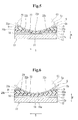
- FIG. 6 is a cross-sectional side view of the thermal head 10 for expressing pressure-sensitive adhesive strength in a second modified example of the embodiment.
- the thermosensitive pressure-sensitive adhesive label 5 and the second platen roller 53 are indicated by alternate long and two short dashes lines, in the same way as in FIGS. 4 and 5 .
- the surface 22 of the thermally active component adhesion preventing layer 20 is formed continuously by the upstream portion 20a, the downstream portion 20b, and the center portion 20c.
- the center portion surface 22c is formed on the protective layer 18, and the upstream portion surface 22a, the downstream portion surface 22b, and the center portion surface 22c are formed continuously.
- the thermal head 10 for expressing pressure-sensitive adhesive strength of the second modified example is different from the thermal head 10 for expressing pressure-sensitive adhesive strength of the embodiment and the first modified example in that the thermal head 10 for expressing pressure-sensitive adhesive strength of the second modified example does not include the center portion surface 22c, and the upstream portion surface 22a and the downstream portion surface 22b are not formed continuously. Detailed descriptions of portions with the same configurations as those of the embodiment are omitted.
- the thermal head 10 for expressing pressure-sensitive adhesive strength of the second modified example includes the upstream portion 20a formed on the upstream side from the heat-generating elements 14 and the downstream portion 20b formed on the downstream side from the heat-generating elements 14. Further, the concavity18a of the protective layer 18 is exposed from between the upstream portion 20a and the downstream portion 20b.
- the upstream portion 20a of the thermally active component adhesion preventing layer 20 is provided with the upstream portion surface 22a
- the downstream portion 20b is provided with the downstream portion surface 22b. More specifically, the upstream portion surface 22a and the downstream portion surface 22b are formed separately with the concave 18a formed on the heat-generating element 14 interposed therebetween. The upstream portion surface 22a and the downstream portion surface 22b are formed along the outer circumferential surface 53a of the second platen roller 53.
- the surfaces (upstream portion surface 22a and downstream portion surface 22b), which are formed on the upstream side and the downstream side of the heat-generating elements 14 and with which the thermosensitive pressure-sensitive adhesive layer 5b of the thermosensitive pressure-sensitive adhesive label 5 comes into surface contact, can be formed without covering the heat-generating elements 14 with the thermally active component adhesion preventing layer 20.
- the thermal head 10 for expressing pressure-sensitive adhesive strength which is excellent in a heat conduction efficiency in addition to the effects of the embodiment, can be formed.
- the surfaces are substantially arc-shaped.
- FIG. 7 is a flowchart of a method of producing the thermal head 10 for expressing pressure-sensitive adhesive strength.
- the method of producing the thermal head 10 for expressing pressure-sensitive adhesive strength of this embodiment includes a heat-generating element formation step S10, an electrode formation step S20, a protective layer formation step S30, and a thermally active component adhesion preventing layer formation step S40.
- the plurality of heat-generating elements 14 are formed on the principal plane 12a of the substrate 12 (see FIG. 2 ).
- a heat-generating resistive material such as Ta-SiO 2 is formed into a film on the principal plane 12a of the substrate 12 by, for example, sputtering, CVD, or vapor deposition.
- the film is patterned to a predetermined outer shape by photolithography to form the plurality of heat-generating elements 14.
- the film is patterned so that the outer shape of the heat-generating element 14 becomes substantially rectangular in a planar view, as illustrated in FIG. 2 .
- the electrodes 16 and 17 electrically connected to the plurality of heat-generating elements 14 are formed on the principal plane 12a of the substrate 12 (see FIG. 2 ).
- metal having a high conductivity such as Au, Cu, or Al is formed into a film by, for example, sputtering, CVD, or vapor deposition on the principal plane 12a of the substrate 12.
- the film is patterned to a predetermined outer shape to form the electrodes 16 and 17 by, for example, photolithography.
- the film is patterned on the downstream side and the upstream side of the heat-generating elements 14 to form the electrodes 16 and 17.
- the electrodes 16 and 17 may be formed by, for example, screen printing.
- the protective layer 18 covering the heat-generating elements 14 and the electrodes 16 and 17 is formed on the principal plane 12a of the substrate 12 (see FIG. 3 ).
- hard ceramics such as Si-O-N or Si-Al-O-N are formed into a film so as to overlap the heat-generating elements 14 and the electrodes 16 and 17 on the principal plane 12a of the substrate 12 by, for example, sputtering, CVD, or vapor deposition to form the protective layer 18.
- the thermally active component adhesion preventing layer 20 that comes into sliding contact with the thermosensitive pressure-sensitive adhesive layer 5b of the thermosensitive pressure-sensitive adhesive label 5 is formed on the upstream side and the downstream side of the conveyance direction S of the thermosensitive pressure-sensitive adhesive label 5 with the heat-generating element 14 interposed therebetween.
- the thermally active component adhesion preventing layer formation step S40 includes a base layer formation step S40A and a surface formation step S40B. Hereinafter, each step is described.
- FIG. 8 is an explanatory diagram of the base layer formation step S40A.
- a base layer 30 made of a base material 30b that is to form the thermally active component adhesion preventing layer 20 later is formed so as to overlap the protective layer 18.
- a material that has low surface energy and is excellent in water repellency and oil repellency such as a silicone-based resin or a fluorine-based resin is used, as described above.
- the base material 30b is applied to the entire surface of the protective layer 18. More specifically, in the base layer formation step S40A, the base material 30b can be applied to the protective layer 18 without masking, and hence, the base layer formation step S40A can be performed easily.
- the base material 30b is applied to the protective layer 18 by, for example, screen printing. Thus, as illustrated in FIG. 8 , an outer surface 30a of the base layer 30 is formed flatly.
- the base material 30b may be applied to the protective layer 18 by dipping, spraying, or brush coating instead of screen printing. Further, depending upon the characteristics of the base material 30b, the application of the base material 30b may pass through a drying step by thermal curing, UV-curing, agent solution reaction, chemical reaction with water or oxygen, or evaporation of a contained agent.
- FIG. 9 is an explanatory diagram of the surface formation step S40B.
- the base layer 30 is processed, thereby forming the surface 22 (see FIG. 4 ) forming part of the top of the thermally active component adhesion preventing layer 20, which is formed continuously between the upstream side and the downstream side of the conveyance direction S with the heat-generating element 14 interposed therebetween and is formed along the outer circumferential surface 53a of the second platen roller 53.
- the surface 22 of the thermally active component adhesion preventing layer 20 is formed by bringing an outer circumferential surface 71a of a polishing roller 71 having a diameter substantially equal to that of the second platen roller 53 (see FIG. 4 ) into contact with the base layer 30 to polish the base layer 30.
- the polishing roller 71 having a diameter substantially equal to or slightly larger than that of the second platen roller 53 (see FIG. 4 ) is prepared.
- the outer circumferential surface 71a of the polishing roller 71 is a polishing surface having a predetermined surface roughness over the entire circumference.
- the surface 22 of the thermally active component adhesion preventing layer 20 is formed by bringing the outer circumferential surface 71a of the polishing roller 71 into contact with the outer surface 30a of the base layer 30 to polish the outer surface 30a while rotating the polishing roller 71 around a center axis O.
- the surface 22 of the thermally active component adhesion preventing layer 20 having a shape following the outer circumferential surface 53a (see FIG. 4 ) of the second platen roller 53 is formed easily with good precision merely by polishing the base layer 30 with the polishing roller 71. Further, the polishing amount of the base layer 30 can be adjusted easily merely by adjusting the relative position between the polishing roller 71 and the base layer 30. This enables the base layer 30 covering the heat-generating elements 14 to be formed to a desired thickness, and hence, the thermal head 10 for expressing pressure-sensitive adhesive strength having a desired heat conduction efficiency can be formed.
- FIG. 10 is an explanatory diagram of the surface formation step S40B using a disk grinder 74.
- the surface 22 of the thermally active component adhesion preventing layer 20 may be formed by bringing the side surface 74a of the disk grinder 74 into contact with the base material 30 to polish the base material 30.
- the disk grinder 74 whose radius of curvature of the side surface 74a is substantially equal to or slightly larger than that of the outer circumferential surface 53a (see FIG. 4 ) of the second platen roller 53 is prepared.
- the side surface 74a of the disk grinder 74 functions as a polishing surface having a predetermined surface roughness over the entire circumference.
- the surface 22 of the thermally active component adhesion preventing layer 20 is formed by bringing the side surface 74a of the disk grinder 74 into contact with the outer surface 30a of the base layer 30 to polish the outer surface 30a while rotating the disk grinder 74 around a center axis P.
- the surface 22 of the thermally active component adhesion preventing layer 20 having a shape following the outer circumferential surface 53a (see FIG. 4 ) of the second platen roller 53 can be formed easily with good precision merely by polishing the base layer 30 with the disk grinder 74. Further, in the same way as described above, the polishing amount of the base layer 30 can be adjusted easily merely by adjusting the relative position between the disk grinder 74 and the base layer 30, and hence, the thermal head 10 for expressing pressure-sensitive adhesive strength having a desired heat conduction efficiency can be formed.
- FIG. 11 is an explanatory diagram of the surface formation step S40B using a die 76.
- the surface 22 of the thermally active component adhesion preventing layer 20 may be formed by pressing an outer circumferential surface 76a of the die 76 against the base layer 30.
- the die 76 whose radius of curvature of the outer circumferential surface 76a is substantially equal to or slightly larger than that of the outer circumferential surface 53a (see FIG. 4 ) of the second platen roller 53 is prepared. Then, the surface 22 of the thermally active component adhesion preventing layer 20 is formed by bringing the outer circumferential surface 76a of the die 76 into contact with the outer surface 30a of the base layer 30 to press the outer surface 30a.
- the surface 22 of the thermally active component adhesion preventing layer 20 having a shape following the outer circumferential surface 53a (see FIG. 4 ) of the second platen roller 53 can be formed easily with good precision merely by pressing the outer circumferential surface 76a of the die 76 against the base layer 30.
- the base layer 30 covering the heat-generating elements 14 can be formed to a desired thickness by adjusting a pressure force, and hence, the thermal head 10 for expressing pressure-sensitive adhesive strength having a desired heat conduction efficiency can be formed.
- FIG. 12 is an explanatory diagram of the surface formation step S40B using a polishing sheet 78.
- the surface 22 of the thermally active component adhesion preventing layer 20 may be formed by conveying the polishing sheet 78 by the second platen roller 53 and bringing the polishing sheet 78 into sliding contact with the base layer 30 to polish the base layer 30.
- the polishing sheet 78 provided with a polishing surface 78a with a predetermined surface roughness is prepared. Then, the polishing sheet 78 is placed between the base layer 30 and the second platen roller 53 while the polishing surface 78a is placed so as to face the outer surface 30a of the base layer 30. Then, the second platen roller 53 is rotated while being pressed against the substrate 12 side to convey the polishing sheet 78, and hence the outer surface 30a of the base layer 30 is polished with the polishing surface 78a of the polishing sheet 78 to form the surface 22 of the thermally active component adhesion preventing layer 20.
- the second platen roller 53 used to form the surface 22 can but need not be mounted in a printer and that the thermal head 10 so formed can subsequently be mounted in a printer.
- the surface 22 of the thermally active component adhesion preventing layer 20 having a shape following the outer circumferential surface 53a of the second platen roller 53 can be formed easily with good precision without using a tool by conveying the polishing sheet 78. Further, the polishing amount can be adjusted easily, and hence, the base layer 30 covering the heat-generating elements 14 can be formed to a desired thickness and the heat-generating elements 14 can be exposed from the base layer 30. Thus, the thermal head 10 for expressing pressure-sensitive adhesive strength having a desired heat conduction efficiency can be formed.
- the base layer 30 of the thermally active component adhesion preventing layer 20 by masking the positions corresponding to the heat-generating elements 14 so that the thermally active component adhesion preventing layer 20 is not formed in regions right above the heat-generating elements 14, for the purpose of preventing a decrease in a heat conduction efficiency.
- the mask is formed by, for example, photolithography, and hence, the step is very complicated.
- the surface processing is performed along the outer circumferential surface 53a of the second platen roller 53 or another body having an equivalent surface. Therefore, it is not necessary to mask the positions corresponding to the heat-generating elements 14.
- the thermally active component adhesion preventing layer 20 having the surface 22 along the outer circumferential surface 53a of the second platen roller 53 can be formed easily.
- the thermally active component adhesion preventing layer 20 in order to ensure a satisfactory heat conduction efficiency, it is necessary to form the thermally active component adhesion preventing layer 20 thin.
- the material itself is expensive, which results in a high production cost.
- the surface 22 of the thermally active component adhesion preventing layer 20 is formed by processing the thick base layer 30, and hence, the thermally active component adhesion preventing layer 20 can be formed to a desired thickness by adjusting a processing amount.
- the base layer 30 before being processed can be formed thick, and hence, a material for forming the thermally active component adhesion preventing layer 20 is not limited.
- the thermal head 10 for expressing pressure-sensitive adhesive strength having a desired heat conduction efficiency can be formed at low cost.
- the thermal head 10 for expressing pressure-sensitive adhesive strength of this embodiment is applied to the pressure-sensitive adhesive strength expressing unit 4 for heating the thermosensitive pressure-sensitive adhesive layer 5b to express pressure-sensitive adhesive strength.
- the thermal head 10 for expressing pressure-sensitive adhesive strength may be applied as the printing thermal head 8 of the printing unit 2 for heating the thermosensitive coloring layer 5a for printing.
- the present invention is preferred particularly for the thermosensitive pressure-sensitive adhesive label 5 having the thermosensitive pressure-sensitive adhesive layer 5b in terms of preventing the adhesion of a thermosensitive coloring component that has come off the thermosensitive coloring layer 5a of the thermosensitive pressure-sensitive adhesive label 5 to be an obstacle for printing and in terms of conveying the thermosensitive coloring component to the downstream side of the heat-generating elements 14 to remove it.
- a material constituting the thermally active component adhesion preventing layer 20 is not limited to the embodiment, and a material that has low surface energy and is excellent in water repellency and oil repellency can be used widely.
- a material that has low surface energy and is excellent in water repellency and oil repellency can be used widely.
- an organic material containing a trace amount of powder such as SiAlON, SiO 2 , SiC, Si-N, TiC, Ti-C, TiO 2 , C (including diamond), Zr, or ZrN may be used.
Landscapes
- Engineering & Computer Science (AREA)
- Manufacturing & Machinery (AREA)
- Physics & Mathematics (AREA)
- Geometry (AREA)
- Electronic Switches (AREA)
- Labeling Devices (AREA)
Abstract
Description
- The present invention relates to a thermal head, a method of producing a thermal head, and a thermal printer including a thermal head.
- Conventionally, an adhesive label has been used, for example, as a food POS label, a distribution/transport label, a medical label, a baggage tag, or a display label for bottles and cans. The adhesive label has a pressure-sensitive adhesion surface provided with a pressure-sensitive adhesive layer on a reverse side of a recording surface (printing surface). The adhesive label is stored with release paper (separator) provisionally attached to the pressure-sensitive adhesion surface and is used after the separator is detached from the pressure-sensitive adhesion surface. However, there is a problem that a separator detached from the pressure-sensitive adhesion surface during use of the adhesive label becomes an industrial waste.
- In recent years, a thermosensitive pressure-sensitive adhesive label that does not use a separator is known. The thermosensitive pressure-sensitive adhesive label is provided with a thermosensitive pressure-sensitive adhesive layer having no pressure-sensitive adhesiveness at room temperature on a reverse surface of a recording surface of a thermosensitive coloring type, and the thermosensitive pressure-sensitive adhesive layer expresses pressure-sensitive adhesive strength when heated.
- As a printer for printing and issuing the above-mentioned type of thermosensitive pressure-sensitive adhesive label, a thermal printer including a thermal head that uses a plurality of heat-generating elements as a heat source is known. In the thermal printer, a thermosensitive pressure-sensitive adhesive label is conveyed while being interposed between a platen roller and a thermal head, and the thermal head is brought into sliding contact with a thermosensitive pressure-sensitive adhesive layer of the traveling thermosensitive pressure-sensitive adhesive label to heat the thermosensitive pressure-sensitive adhesive layer, to thereby allow the layer to express pressure-sensitive adhesive strength.
- The surface of the thermal head is constantly in contact with the thermosensitive pressure-sensitive adhesive layer. Therefore, there is a problem that a thermally active component such as a thermosensitive pressure-sensitive adhesive or a denatured substance of a thermosensitive pressure-sensitive adhesive (substance changed chemically with heat or carbonized substance) adheres to the surface of the thermal head. The thermally active component adhering to the surface of the thermal head causes resistance to the conveyance of the thermosensitive pressure-sensitive adhesive label, which may cause suspension or bending of a traveling thermosensitive pressure-sensitive adhesive label, or a conveyance failure such as paper jam. Further, the thermally active component adhering to the surface of the thermal head hinders the transmission of heat, and hence, a heat conduction efficiency may be degraded.
-
FIG. 13 is an explanatory diagram of a conventionalthermal head 10 for expressing pressure-sensitive adhesive strength. - In order to solve the above-mentioned problems, as illustrated in
FIG. 13 , thethermal head 10 for expressing pressure-sensitive adhesive strength has been proposed in which a heat-generatingelement 14 is covered with aprotective layer 18, and two lines of thermally active componentadhesion preventing layers 20 are provided on an upper surface of theprotective layer 18 to be substantially in parallel to each other so as to sandwich a region right above the heat-generating element 14 (see, for example, Japanese Patent Application Laid-open No.2004-50507 - According to Japanese Patent Application Laid-open No.
2004-50507 adhesive label 5 to be swept out onto the thermally active componentadhesion preventing layer 20 from the region right above the heat-generatingelement 14, and hence, the thermally active component D can be prevented from remaining in the region right above the heat-generatingelement 14. - However, the
thermal head 10 for expressing pressure-sensitive adhesive strength described in Japanese Patent Application Laid-open No.2004-50507 - As illustrated in
FIG. 13 , in thethermal head 10 for expressing pressure-sensitive adhesive strength of Japanese Patent Application Laid-open No.2004-50507 adhesion preventing layers 20 are formed in two rows with the region right above the heat-generatingelement 14 opened. Therefore, astep 21 provided by the thermally active componentadhesion preventing layer 20 is formed on each of an upstream side and a downstream side of the heat-generatingelement 14. - When the thermosensitive pressure-sensitive
adhesive label 5 is conveyed by aplaten roller 53, the thermosensitive pressure-sensitiveadhesive label 5 comes into sliding contact with thestep 21 of the thermally active componentadhesion preventing layer 20. Therefore, the thermally active component D adhering to the thermosensitive pressure-sensitiveadhesive label 5 is caught on thestep 21 to remain in a gap between theplaten roller 53 and theprotective layer 18 and may adhere to the region above the heat-generatingelement 14 and the periphery of the heat-generatingelement 14. - It is an object of the present invention to provide a thermal head, a method of producing a thermal head, and a thermal printer capable of preventing a thermally active component from adhering to a region above a heat-generating element and the periphery of the heat-generating element, or reducing the occurrence thereof.
- In order to solve the above-mentioned problems, according to an exemplary embodiment of the present invention, there is provided a thermal head, including a heat-generating element on a principal plane of a substrate, the thermal head being configured to heat a thermosensitive layer of a thermosensitive label conveyed while being interposed between the heat-generating element and a platen roller opposed to the heat-generating element, in which the principal plane of the substrate has a thermally active component adhesion preventing layer formed thereon, which comes into sliding contact with the thermosensitive layer and is formed at least on an upstream side and a downstream side of the heat-generating element in a conveyance direction of the thermosensitive label, and in which a surface of the thermally active component adhesion preventing layer is formed in a shape following an outer circumferential surface of the platen roller.
- According to the present invention, the surface of the thermally active component adhesion preventing layer is formed along the outer circumferential surface of the platen roller without any step. Therefore, when the thermosensitive label is conveyed while being interposed between the platen roller and the heat-generating element, the thermosensitive layer of the thermosensitive label and the surface of the thermally active component adhesion preventing layer can come into surface contact with each other. Herein, the thermally active component adhesion preventing layer has a property of preventing the adhesion of the thermally active component. Therefore, the thermally active component adhering to the thermosensitive layer of the thermosensitive label is conveyed to the downstream side of the heat-generating element to be removed from the region right above and the periphery of the heat-generating element without being caught on the surface of the thermally active component adhesion preventing layer or remaining in a gap between the platen roller and the thermally active component adhesion preventing layer.
- Thus, the thermally active component can be prevented from remaining and from adhering to the region right above the heat-generating element and the periphery of the heat-generating element.
- Further, in the thermal head of the present invention, the thermally active component adhesion preventing layer is formed continuously between the upstream side and the downstream side of the heat-generating element in the conveyance direction, and in which the surface of the thermally active component adhesion preventing layer is formed in the shape following the outer circumferential surface of the platen roller between the upstream side and the downstream side of the heat-generating element in the conveyance direction.
- According to the present invention, the thermally active component adhesion preventing layer is formed so as to cover the heat-generating element. Therefore, the thermally active component can be reliably prevented from adhering to the surface of the thermally active component adhesion preventing layer corresponding to the heat-generating element.
- Further, the surface of the thermally active component adhesion preventing layer is formed along an outer circumferential shape of the platen roller between the upstream side and the downstream side of the heat-generating element in the conveyance direction of the thermosensitive label, and hence, the thermosensitive layer of the thermosensitive label and the thermally active component adhesion preventing layer are brought into surface contact with each other in a wide range without any step from the upstream side to the downstream side. Thus, the thermally active component can be conveyed to the downstream side of the heat-generating element to be removed reliably without being caught on the surface of the thermally active component adhesion preventing layer. Further, a gap is not formed between the platen roller and the thermally active component adhesion preventing layer, and hence, the thermally active component does not remain in a gap between the platen roller and the thermally active component adhesion preventing layer.
- Thus, the thermally active component can be reliably prevented from remaining and from adhering to the region above the heat-generating element and the periphery of the heat-generating element.
- Further, the surface of the thermally active component adhesion preventing layer is formed along the outer circumferential shape of the platen roller, and hence, the surface is formed substantially in an arc shape between the upstream side and the downstream side of the heat-generating element in the conveyance direction of the thermosensitive label. Therefore, the portion of the thermally active component adhesion preventing layer corresponding to the heat-generating element is formed thinner compared with portions corresponding to the upstream side and the downstream side in the conveyance direction of the thermosensitive label. Thus, a decrease in a heat conduction efficiency is suppressed when heat is transmitted from the heat-generating element to the thermosensitive layer via the thermally active component adhesion preventing layer.
- Further, in the thermal head of the present invention, the thermally active component adhesion preventing layer contains one of a silicone-based resin and a fluorine-based resin as a main component.
- According to the present invention, the thermally active component adhesion preventing layer that has low surface energy and is excellent in water repellency and oil repellency can be formed. Thus, the thermally active component adhering to the thermosensitive layer of the thermosensitive label can be conveyed to the downstream side of the heat-generating element together with the conveyance of the thermosensitive label to be removed reliably without being caught on the surface of the thermally active component adhesion preventing layer or remaining. Therefore, the thermally active component can be prevented from adhering to the region above the heat-generating element and the periphery of the heat-generating element.
- Further, in the thermal head of the present invention, the thermally active component adhesion preventing layer contains, as a main component, a material obtained by adding powder of one of an oxide, a nitride, and an oxynitride of one of silicon, a silicon-based alloy, titanium, a titanium-based alloy, tantalum, and a tantalum-based alloy to a fluorine-based resin.
- According to the present invention, the abrasion resistance of the thermally active component adhesion preventing layer can be enhanced while water repellency and oil repellency are kept. Thus, a thermal head can be provided, which is capable of preventing the thermally active component from adhering to the region above the heat-generating element and the periphery of the heat-generating element and which is excellent in abrasion resistance.
- Further, in the thermal head of the present invention, the thermally active component adhesion preventing layer contains, as a main component, a material obtained by adding one of metal and carbon to a fluorine-based resin.
- According to the present invention, the thermally active component adhesion preventing layer is allowed to have conductivity while keeping water repellency and oil repellency by adding metal or carbon to form the thermally active component adhesion preventing layer. Thus, static electricity generated when the thermosensitive label and the thermally active component adhesion preventing layer come into sliding contact with each other can be discharged from the thermally active component adhesion preventing layer. Thus, the thermally active component can be prevented from adhering to the region above the heat-generating element and the periphery of the heat-generating element due to static electricity, and electrostatic breakdown of an electronic element such as the heat-generating element can be prevented.
- Further, the thermal head of the present invention, the thermosensitive label is a thermosensitive pressure-sensitive adhesive label, and the thermosensitive layer is a thermosensitive pressure-sensitive adhesive layer for expressing pressure-sensitive adhesive strength by heating.
- According to the present invention, the thermally active component adhesion preventing layer has a property of preventing the adhesion of the thermally active component. Therefore, even a thermally active component having pressure-sensitive adhesiveness is conveyed to the downstream side of the heat-generating element together with the movement of the thermosensitive label to be removed without being caught on the surface of the thermally active component adhesion preventing layer. Thus, the thermally active component adhesion preventing layer is preferred for a thermosensitive pressure-sensitive adhesive label provided with a thermosensitive pressure-sensitive adhesive layer that expresses pressure-sensitive adhesive strength by heating.
- Further, a method of producing a thermal head according to an exemplary embodiment of the present invention includes a heat-generating element on a principal plane of a substrate, the thermal head being configured to heat a thermosensitive layer of a thermosensitive label conveyed while being interposed between the heat-generating element and a platen roller opposed to the heat-generating element, the method including forming a thermally active component adhesion preventing layer that comes into sliding contact with the thermosensitive layer on the principal plane of the substrate at least on an upstream side and a downstream side of the heat-generating element in a conveyance direction of the thermosensitive label, in which the forming a thermally active component adhesion preventing layer includes: forming a base layer of the thermally active component adhesion preventing layer on the principal plane of the substrate so that the base layer overlaps the heat-generating element; and after forming the base layer, forming a surface along an outer circumferential surface of the platen roller by processing the base layer at least on the upstream side and the downstream side of the heat-generating element in the conveyance direction of the thermosensitive label.
- According to the related art, it is necessary to form a base layer of a thermally active component adhesion preventing layer by masking the positions corresponding to the heat-generating elements so that the thermally active component adhesion preventing layer is not formed in a region right above the heat-generating element, for the purpose of preventing a decrease in a heat conduction efficiency. The mask is formed by, for example, photolithography, and hence, the step is very complicated. However, according to the present invention, after the base layer of the thermally active component adhesion preventing layer is formed so as to overlap the heat-generating elements, the surface processing is performed along the outer circumferential surface of the platen roller. Therefore, it is not necessary to mask the positions corresponding to the heat-generating elements. Thus, the thermally active component adhesion preventing layer having the surface along the outer circumferential surface of the platen roller can be formed easily.
- Further, in the related art, in order to ensure a satisfactory heat conduction efficiency, it is necessary to form the thermally active component adhesion preventing layer thin. Therefore, a material for forming the thermally active component adhesion preventing layer is limited to, for example, a silicone-based resin. However, according to the present invention, the thick base layer is processed to form the surface of the thermally active component adhesion preventing layer. Therefore, the center portion of the thermally active component adhesion preventing layer can be formed to a desired thickness by adjusting a processing amount. Further, the base layer before processing can be formed thick, and hence, the material for forming the thermally active component adhesion preventing layer is not limited, and a thermal head having a desired heat conduction efficiency can be formed.
- Further, in the method of producing a thermal head of the present invention, the forming a surface includes bringing an outer circumferential surface of a polishing roller having a diameter substantially equal to a diameter of the platen roller into contact with the base layer to polish the base layer.
- According to the present invention, the outer circumferential surface of the polishing roller has a diameter substantially equal to that of the platen roller. Therefore, the surface of the thermally active component adhesion preventing layer having a shape following the outer circumferential surface of the platen roller can be formed easily with good precision merely by polishing the base layer with the polishing roller.
- Further, the polishing amount can be adjusted easily, and hence, the base layer covering the heat-generating elements can be formed to a desired thickness and the heat-generating elements can be exposed from the base layer. Thus, a thermal head having a desired heat conduction efficiency can be formed.
- Further, in the method of producing a thermal head of the present invention, the forming a surface includes bringing a side surface of a disk grinder into contact with the base layer to polish the base layer, and the side surface of the disk grinder is formed on a curved surface having a radius of curvature substantially equal to a radius of curvature of the outer circumferential surface of the platen roller.
- According to the present invention, the side surface of the disk grinder is formed on the curved surface having a radius of curvature substantially equal to that of the platen roller. Therefore, the surface of the thermally active component adhesion preventing layer having a shape following the outer circumferential surface of the platen roller can be formed easily with good precision merely by polishing the base layer with the disk grinder. Further, in the same way as described above, the polishing amount can be adjusted easily, and hence, a thermal head having a desired heat conduction efficiency can be formed.
- Further, in the method of producing a thermal head of the present invention, the forming a surface includes pressing an outer circumferential surface of a die against the base layer, and the outer circumferential surface of the die is formed on a curved surface having a radius of curvature substantially equal to a radius of curvature of the outer circumferential surface of the platen roller.
- According to the present invention, the outer circumferential surface of the die is formed on the curved surface having a radius of curvature substantially equal to that of the platen roller. Therefore, the surface of the thermally active component adhesion preventing layer having a shape following the outer circumferential surface of the platen roller can be formed easily with good precision merely by pressing the outer circumferential surface of the die against the base layer.
- Further, the base layer covering the heat-generating elements can be formed to a desired thickness by adjusting the pressure force of the die. Therefore, a thermal head having a desired heat conduction efficiency can be formed.
- Further, in the method of producing a thermal head of the present invention, the forming a surface includes conveying a polishing sheet with the platen roller and bringing the polishing sheet into sliding contact with the base layer to polish the base layer.
- According to the present invention, the surface of the thermally active component adhesion preventing layer having a shape following the outer circumferential surface of the platen roller can be formed easily with good precision without using a tool. Further, the polishing amount can be adjusted easily, and hence, the base layer covering the heat-generating elements can be formed to a desired thickness and the heat-generating elements can be exposed from the base layer. Thus, a thermal head having a desired heat conduction efficiency can be formed.
- A thermal printer of the present invention includes the above-mentioned thermal head.
- According to the present invention, a high performance thermal printer having a high heat conduction efficiency is obtained without any conveyance defects of a thermosensitive label by providing a thermal head capable of preventing a thermally active component from adhering to a region above a heat-generating element and the periphery of the heat-generating element.
- According to the present invention, the surface of the thermally active component adhesion preventing layer is formed along the outer circumferential surface of the platen roller without any step. Therefore, when the thermosensitive label is conveyed while being interposed between the platen roller and the heat-generating element, the thermosensitive layer of the thermosensitive label and the surface of the thermally active component adhesion preventing layer can come into surface contact with each other. Herein, the thermally active component adhesion preventing layer has a property of preventing the adhesion of the thermally active component. Therefore, the thermally active component adhering to the thermosensitive layer of the thermosensitive label is conveyed to the downstream side of the heat-generating element to be removed from the region right above and the periphery of the heat-generating element without being caught on the surface of the thermally active component adhesion preventing layer or remaining in a gap between the platen roller and the thermally active component adhesion preventing layer.
- Thus, the thermally active component can be prevented from remaining in and from adhering to the region above the heat-generating element and the periphery of the heat-generating element.
- Embodiments of the present invention will now be described by way of further example only and with reference to the accompanying drawings, in which:
-
FIG. 1 is a schematic view of a thermal printer; -
FIG. 2 is a plan view of a thermal head for expressing pressure-sensitive adhesive strength; -
FIG. 3 is a cross-sectional perspective view of the thermal head for expressing pressure-sensitive adhesive strength; -
FIG. 4 is a cross-sectional side view taken along line A-A ofFIG. 2 ; -
FIG. 5 is a cross-sectional side view of a thermal head for expressing pressure-sensitive adhesive strength in a first modified example of an embodiment of the present invention; -
FIG. 6 is a cross-sectional side view of a thermal head for expressing pressure-sensitive adhesive strength in a second modified example of the embodiment; -
FIG. 7 is a flowchart of a method of producing a thermal head for expressing pressure-sensitive adhesive strength; -
FIG. 8 is an explanatory diagram of a base layer formation step; -
FIG. 9 is an explanatory diagram of a surface formation step; -
FIG. 10 is an explanatory diagram of a surface formation step using a disk grinder; -
FIG. 11 is an explanatory diagram of a surface formation step using a die; -
FIG. 12 is an explanatory diagram of a surface formation step using a polishing sheet; and -
FIG. 13 is an explanatory diagram of a conventional thermal head for expressing pressure-sensitive adhesive strength. - Hereinafter, a thermal head according to an embodiment of the present invention is described with reference to the drawings.
- In the following, first, an outline of a thermal printer is described, and then, a thermal head of this embodiment is described.
-
FIG. 1 is a schematic view of a thermal printer 1. - As illustrated in
FIG. 1 , a thermal printer 1 prints a barcode, a price, or the like on one surface of a thermosensitive pressure-sensitive adhesive label 5 (thermosensitive label) unrolled from a sheet roll R and conveyed, cuts the thermosensitive pressure-sensitive adhesive label 5 to a desired length, causes the other surface of the thermosensitive pressure-sensitive adhesive label 5 to express pressure-sensitive adhesive strength, and issues the label. - In
FIG. 1 , the conveyance direction of the thermosensitive pressure-sensitive adhesive label 5 is defined as S. The conveyance direction S is directed from the right side to the left side inFIG. 1 . The right side is defined as an upstream side of the conveyance direction S, and the left side is defined as a downstream side of the conveyance direction S. In the following description, the upstream side of the conveyance direction S is sometimes merely referred to as an upstream side, and the downstream side of the conveyance direction S is sometimes merely referred to as a downstream side. - Further, the inside surface of the sheet roll R corresponds to the one surface of the thermosensitive pressure-
sensitive adhesive label 5, and athermosensitive coloring layer 5a that is discolored by heating to be printed is formed on the one surface. Further, the outside surface of the sheet roll R corresponds to the other surface of the thermosensitive pressure-sensitive adhesive label 5, and a thermosensitive pressure-sensitive adhesive layer 5b (thermosensitive layer) that is heated to express pressure-sensitive adhesive strength is formed on the other surface. - The thermal printer 1 includes a
printing unit 2 for performing printing with respect to thethermosensitive coloring layer 5a by heating thethermosensitive coloring layer 5a from the one surface side (upper side inFIG. 1 ) of the thermosensitive pressure-sensitive adhesive label 5 to be conveyed, acutter unit 3 for cutting the thermosensitive pressure-sensitive adhesive label 5 unrolled from the sheet roll R to a desired length, and a pressure-sensitive adhesivestrength expressing unit 4 for causing the thermosensitive pressure-sensitive adhesive layer 5b to express pressure-sensitive adhesive strength by heating the thermosensitive pressure-sensitive adhesive layer 5b from the other surface side (lower side inFIG. 1 ) of the thermosensitive pressure-sensitive adhesive label 5. A thermal head according to the present invention is athermal head 10 for expressing pressure-sensitive adhesive strength described later, and constitutes the pressure-sensitive adhesivestrength expressing unit 4. - The
printing unit 2 is placed on the downstream side of the sheet roll R and includes afirst platen roller 51 and a printingthermal head 8. The printingthermal head 8 has a plurality of heat-generating elements (not shown) and is placed so as to face thethermosensitive coloring layer 5a of the thermosensitive pressure-sensitive adhesive label 5. Further, thefirst platen roller 51 is placed on an opposite side of the printingthermal head 8 with the thermosensitive pressure-sensitive adhesive label 5 interposed therebetween. - The printing
thermal head 8 is biased to thefirst platen roller 51 side by a spring or the like (not shown). Therefore, the thermosensitive pressure-sensitive adhesive label 5 is interposed elastically between the printingthermal head 8 and thefirst platen roller 51. When the printingthermal head 8 is supplied with power from a power source (not shown), the plurality of heat-generating elements generate heat, and thethermosensitive coloring layer 5a of the thermosensitive pressure-sensitive adhesive label 5 is heated to be printed with letters, graphics, and the like. Further, when thefirst platen roller 51 is rotated by a drive source (not shown), the thermosensitive pressure-sensitive adhesive label 5 is conveyed while thethermosensitive coloring layer 5a and the printingthermal head 8 are in sliding contact with each other. - The
cutter unit 3 is placed on the downstream side of theprinting unit 2 and has amovable blade 55 and a fixedblade 57 on either side of the thermosensitive pressure-sensitive adhesive label 5. Themovable blade 55 is capable of reciprocating and sliding against the fixedblade 57 and cuts the printed thermosensitive pressure-sensitive adhesive label 5 to a desired length. - The pressure-sensitive adhesive
strength expressing unit 4 is placed on the downstream side of thecutter unit 3 and includes a second platen roller 53 (corresponding to a "platen roller" in the claims) and thethermal head 10 for expressing pressure-sensitive adhesive strength (corresponding to a "thermal head" in the claims). Thethermal head 10 for expressing pressure-sensitive adhesive strength includes a plurality of heat-generating elements 14 (seeFIG. 2 ) as described later and is placed so as to face the thermosensitive pressure-sensitive adhesive layer 5b of the thermosensitive pressure-sensitive adhesive label 5. Further, thesecond platen roller 53 is placed on the opposite side of thethermal head 10 for expressing pressure-sensitive adhesive strength with the thermosensitive pressure-sensitive adhesive label 5 interposed therebetween. - The
thermal head 10 for expressing pressure-sensitive adhesive strength is biased to thesecond platen roller 53 side by a spring or the like (not shown). Therefore, the thermosensitive pressure-sensitive adhesive label 5 is interposed elastically between thethermal head 10 for expressing pressure-sensitive adhesive strength and thesecond platen roller 53. - Then, when the
thermal head 10 for expressing pressure-sensitive adhesive strength is supplied with power from a power source (not shown), the plurality of heat-generatingelements 14 generate heat, and the thermosensitive pressure-sensitive adhesive layer 5b of the thermosensitive pressure-sensitive adhesive label 5 is heated to express pressure-sensitive adhesive strength. Further, when thesecond platen roller 53 is rotated by a drive source (not shown), the thermosensitive pressure-sensitive adhesive label 5 is conveyed while the thermosensitive pressure-sensitive adhesive layer 5b and thethermal head 10 for expressing pressure-sensitive adhesive strength are in sliding contact with each other. - Next, the
thermal head 10 for expressing pressure-sensitive adhesive strength of this embodiment is described. -
FIG. 2 is a plan view of thethermal head 10 for expressing pressure-sensitive adhesive strength. -
FIG. 3 is a cross-sectional perspective view of thethermal head 10 for expressing pressure-sensitive adhesive strength. - In
FIG. 2 , for ease of understanding, theprotective layer 18 and a thermally active component adhesion preventing layer 20 (seeFIG. 3 ) described later are omitted. Further, inFIGS. 2 and3 , the conveyance direction S of the thermosensitive pressure-sensitive adhesive label 5 is directed from the right side to the left side. The right side is defined as an upstream side and the left side is defined as a downstream side. Further, in the following, the width direction of the thermosensitive pressure-sensitive adhesive label 5 to be conveyed is defined as W, and the thickness direction of thethermal head 10 for expressing pressure-sensitive adhesive strength orthogonal to the conveyance direction S and the width direction W is defined as H. - As illustrated in
FIG. 2 , thethermal head 10 for expressing pressure-sensitive adhesive strength includes asubstrate 12, the plurality of heat-generatingelements 14 formed on aprincipal plane 12a of thesubstrate 12, andelectrodes elements 14. Further, as illustrated inFIG. 3 , theprotective layer 18 covering the heat-generatingelements 14 and theelectrodes adhesion preventing layer 20 covering theprotective layer 18 are formed on theprincipal plane 12a of thesubstrate 12. - As illustrated in
FIG. 2 , thesubstrate 12 is shaped to be substantially rectangular in plan view, having a short side in the conveyance direction S of the thermosensitive pressure-sensitive adhesive label 5 (seeFIG. 1 ) and a long side in the width direction W of the thermosensitive pressure-sensitive adhesive label 5 (seeFIG. 1 ). Thesubstrate 12 is formed of, for example, ceramics and has an insulating property. - On the
principal plane 12a of thesubstrate 12, the plurality of heat-generatingelements 14 are formed. The heat-generatingelement 14 is shaped to be substantially rectangular in a planar view. The heat-generatingelement 14 is a heat-generating resistive element for generating heat when supplied with a current. The heat-generatingelements 14 are arranged at a substantially equal interval in the width direction W substantially at the center of theprincipal plane 12a of thesubstrate 12 in the conveyance direction S. The heat-generatingelement 14 is formed of, for example, a heat-generating resistive material such as tantalum (Ta) and silicon oxide (SiO2). - Further, the
electrodes elements 14 are formed on theprincipal plane 12a of thesubstrate 12. Theelectrodes electrodes elements 14 in the conveyance direction S and connected electrically to the heat-generatingelements 14. Further, theelectrodes elements 14 are supplied with a current from the power source through theelectrodes - As illustrated in
FIG. 3 , theprotective layer 18 is formed so as to cover the heat-generatingelements 14 and theelectrodes principal plane 12a of thesubstrate 12. Theprotective layer 18 prevents the surfaces of the heat-generatingelements 14 and theelectrodes protective layer 18 prevents the thermosensitive pressure-sensitive adhesive label 5 and the heat-generatingelements 14 and theelectrodes sensitive adhesive label 5 is conveyed. - The
protective layer 18 is formed of, for example, hard ceramics such as Si-O-N or Si-Al-O-N. The thickness of theprotective layer 18 is formed so as to be substantially uniform on the heat-generatingelements 14 and theelectrodes elements 14 in the conveyance direction S are covered with theelectrodes protective layer 18 having substantially uniform thickness is formed on the heat-generatingelements 14 and theelectrodes elements 14, is formed in a region covering the surface of the heat-generatingelements 14 between theelectrodes -
FIG. 4 is a cross-sectional side view taken along the line A-A ofFIG. 2 . InFIG. 4 , for ease of description, the thermosensitive pressure-sensitive adhesive label 5 and thesecond platen roller 53 are indicated by alternate long and two short dashes lines. - As illustrated in
FIG. 4 , the thermally active componentadhesion preventing layer 20 is formed on the uppermost surface of theprincipal plane 12a of thesubstrate 12. - The thermally active component
adhesion preventing layer 20 is formed continuously between the upstream side and the downstream side of the conveyance direction S across the heat-generatingelements 14 so as to cover the underlyingprotective layer 18. - The thermally active component
adhesion preventing layer 20 includes at least anupstream portion 20a formed on the upstream side in the conveyance direction S across the heat-generatingelements 14 and adownstream portion 20b formed on the downstream side in the conveyance direction S across the heat-generatingelements 14. - The thermally active component
adhesion preventing layer 20 of this embodiment includes theupstream portion 20a covering theelectrode 17 on the upstream side, thedownstream portion 20b covering theelectrode 16 on the downstream side, and acenter portion 20c covering the heat-generatingelements 14 between theupstream portion 20a and thedownstream portion 20b. Theupstream portion 20a, thedownstream portion 20b, and thecenter portion 20c are formed continuously. - The thermally active component
adhesion preventing layer 20 is in sliding contact with the thermosensitive pressure-sensitive adhesive layer 5b, when the thermosensitive pressure-sensitive adhesive label 5 is conveyed while being interposed between the heat-generatingelements 14 and thesecond platen roller 53. - The thermally active component
adhesion preventing layer 20 is formed of a material that has low surface energy and is excellent in water repellency and oil repellency, for example, a silicon-based resin or a fluorine-based resin. Thus, the thermally active componentadhesion preventing layer 20 has a property of preventing the adhesion of the thermally active component D of the thermosensitive pressure-sensitive adhesive layer 5b. - Further, the thermally active component
adhesion preventing layer 20 may be formed of a material obtained by adding powder of an oxide, a nitride, or an oxynitride of silicon, a silicon-based alloy, titanium, a titanium-based alloy, tantalum, or a tantalum-based alloy to a fluorine-based resin. This enables the formation of the thermally active componentadhesion preventing layer 20 that has low surface energy, keeps property excellent in water repellency and oil repellency, and is excellent in abrasion resistance. - Further, the thermally active component
adhesion preventing layer 20 may be formed of a material obtained by adding metal or carbon to a fluorine-based resin. This allows the thermally active componentadhesion preventing layer 20 to have conductivity while having low surface energy and keeping property excellent in water repellency and oil repellency. Then, even when the thermosensitive pressure-sensitive adhesive layer 5b and the thermally active componentadhesion preventing layer 20 come into sliding contact with each other to generate static electricity when the thermosensitive pressure-sensitive adhesive label 5 is conveyed, static electricity can be discharged from the thermally active componentadhesion preventing layer 20 gradually. Accordingly, electrostatic breakdown of electronic elements such as the heat-generatingelements 14 can be prevented. - It is desired that the hardness of the thermally active component
adhesion preventing layer 20 be set, for example, in a range of 2B to 5B in terms of pencil hardness, although depending upon the kind of the thermosensitive pressure-sensitive adhesive label 5. The hardness of the thermally active componentadhesion preventing layer 20 can be adjusted by, for example, the kind and addition amount of an additive to a material. - In the case where the adhesion between the surface of the
protective layer 18 and a resin material for forming the thermally active componentadhesion preventing layer 20 is poor, the thermally active componentadhesion preventing layer 20 may be formed through an intermediate film (primer) that is formed of a silane coupling agent or the like and has excellent adhesion. Further, the thermally active componentadhesion preventing layer 20 may be formed by solving the problem of surface roughness of theprotective layer 18 by mechanical polishing or chemical polishing to enhance the adhesion with respect to a resin material. - In a
surface 22 forming part of the top of the thermally active componentadhesion preventing layer 20, anupstream portion surface 22a formed in theupstream portion 20a of the thermally active componentadhesion preventing layer 20, acenter portion surface 22c formed in thecenter portion 20c, and adownstream portion surface 22b formed in thedownstream portion 20b are formed continuously along an outercircumferential surface 53a of thesecond platen roller 53. Thesurface 22 is therefore substantially arc-shaped. Thesurface 22 of the thermally active componentadhesion preventing layer 20 is a sliding-contact surface that comes into sliding contact with the thermosensitive pressure-sensitive adhesive layer 5b when the thermosensitive pressure-sensitive adhesive label 5 is conveyed. - The
surface 22 of the thermally active componentadhesion preventing layer 20 has a substantially arc shape that is substantially concentric with thesecond platen roller 53 when viewed from the width direction W. - The radius of curvature of the
surface 22 of the thermally active componentadhesion preventing layer 20 is set to be slightly larger than that of the outercircumferential surface 53a of thesecond platen roller 53. - By forming the
surface 22 of the thermally active componentadhesion preventing layer 20 as described above, thecenter portion surface 22c and the thermosensitive pressure-sensitive adhesive layer 5b of the thermosensitive pressure-sensitive adhesive label 5 can be reliably brought into surface contact with each other, when the thermosensitive pressure-sensitive adhesive label 5 is conveyed while being interposed between thethermal head 10 for expressing pressure-sensitive adhesive strength and thesecond platen roller 53. Thus, the heat generated by the heat-generatingelements 14 can be transmitted to the thermosensitive pressure-sensitive adhesive layer 5b without fail, and the generated thermally active component D can be conveyed to the downstream side of the heat-generatingelements 14 without being caught on into thesurface 22 of the thermally active componentadhesion preventing layer 20. Further, a gap is not formed between thesecond platen roller 53 and thecenter portion surface 22c, and hence, the thermally active component D does not remain in a gap between thesecond platen roller 53 and the thermally active componentadhesion preventing layer 20. - Further, a slight gap is formed between the outer
circumferential surface 53a of thesecond platen roller 53 and theupstream portion surface 22a and thedownstream portion surface 22b of the thermally active componentadhesion preventing layer 20. Thus, the thermosensitive pressure-sensitive adhesive label 5 is conveyed without being caught on into theupstream portion surface 22a and thedownstream portion surface 22b while coming into surface contact with thecenter portion surface 22c. Further, the thermally active component D of the thermosensitive pressure-sensitive adhesive layer 5b is removed without being caught on thedownstream portion surface 22b. - Further, the
surface 22 of the thermally active componentadhesion preventing layer 20 is formed along the outercircumferential surface 53a of thesecond platen roller 53, and hence thecenter portion 20c of the thermally active componentadhesion preventing layer 20 is formed thinner than theupstream portion 20a and thedownstream portion 20b. Therefore, when heat is transmitted from the heat-generatingelements 14 to the thermosensitive pressure-sensitive adhesive layer 5b via the thermally active componentadhesion preventing layer 20, a decrease in a heat conduction efficiency is suppressed. - According to the present invention, the
surface 22 of the thermally active componentadhesion preventing layer 20 is formed without any step along the outercircumferential surface 53a of thesecond platen roller 53, and hence, the thermosensitive pressure-sensitive adhesive layer 5b of the thermosensitive pressure-sensitive adhesive label 5 and thesurface 22 of the thermally active componentadhesion preventing layer 20 can come into surface contact with each other, when the thermosensitive pressure-sensitive adhesive label 5 is conveyed while being interposed between thesecond platen roller 53 and the heat-generatingelements 14. Herein, the thermally active componentadhesion preventing layer 20 has a property of preventing the adhesion of the thermally active component D. Therefore, the thermally active component D adhering to the thermosensitive pressure-sensitive adhesive layer 5b of the thermosensitive pressure-sensitive adhesive label 5 is conveyed to the downstream side of the heat-generatingelements 14 to be removed from the region right above the heat-generatingelements 14 without being caught on thesurface 22 of the thermally active componentadhesion preventing layer 20 and without remaining in a gap between thesecond platen roller 53 and the thermally active componentadhesion preventing layer 20. - Accordingly, the thermally active component D can be prevented from remaining in the periphery of the heat-generating
elements 14 and the thermally active component D can be prevented from adhering to the region above the heat-generatingelements 14 and the periphery of the heat-generating element. -
FIG. 5 is a cross-sectional side view of thethermal head 10 for expressing pressure-sensitive adhesive strength in a first modified example of the embodiment. InFIG. 5 , for ease of description, the thermosensitive pressure-sensitive adhesive label 5 and thesecond platen roller 53 are indicated by alternate long and two short dashes lines, in the same way as inFIG. 4 . - As illustrated in
FIG. 4 , in thethermal head 10 for expressing pressure-sensitive adhesive strength of the embodiment, the thermally active componentadhesion preventing layer 20 includes theupstream portion 20a, thedownstream portion 20b, and thecenter portion 20c, and theupstream portion 20a, thedownstream portion 20b, and thecenter portion 20c are formed continuously. - In contrast, as illustrated in
FIG. 5 , thethermal head 10 for expressing pressure-sensitive adhesive strength of the first modified example is different from thethermal head 10 for expressing pressure-sensitive adhesive strength of the embodiment in that the thermally active componentadhesion preventing layer 20 includes theupstream portion 20a and thedownstream portion 20b, and theupstream portion 20a and thedownstream portion 20b are formed separately. Detailed descriptions of portions with the same configurations as those of the embodiment are omitted. - As illustrated in
FIG. 5 , the thermally active componentadhesion preventing layer 20 of thethermal head 10 for expressing pressure-sensitive adhesive strength of the first modified example includes theupstream portion 20a covering theelectrode 17 on the upstream side and thedownstream portion 20b covering theelectrode 16 on the downstream side. Further, theprotective layer 18 is exposed from between theupstream portion 20a and thedownstream portion 20b of the thermally active componentadhesion preventing layer 20. - The
upstream portion surface 22a is formed on theupstream portion 20a of the thermally active componentadhesion preventing layer 20. Further, thedownstream portion surface 22b is formed on thedownstream portion 20b of the thermally active componentadhesion preventing layer 20. Further, thecenter portion surface 22c is formed on theprotective layer 18 exposed from between theupstream portion 20a and thedownstream portion 20b of the thermally active componentadhesion preventing layer 20. Theupstream portion surface 22a, thedownstream portion surface 22b, and thecenter portion surface 22c are formed continuously along the outercircumferential surface 53a of thesecond platen roller 53 and function as a sliding-contact surface that comes into sliding contact with the thermosensitive pressure-sensitive adhesive layer 5b when the thermosensitive pressure-sensitive adhesive label 5 is conveyed. - According to the first modified example of the embodiment, the surfaces (
upstream portion surface 22a,downstream portion surface 22b, andcenter portion surface 22c), which are formed continuously between the upstream side and the downstream side of the heat-generatingelements 14 and with which the thermosensitive pressure-sensitive adhesive layer 5b of the thermosensitive pressure-sensitive adhesive label 5 comes into surface contact, can be formed without covering the heat-generatingelements 14 with the thermally active componentadhesion preventing layer 20. Thus, thethermal head 10 for expressing pressure-sensitive adhesive strength, which is excellent in a heat conduction efficiency in addition to the effects of the embodiment, can be formed. - The surfaces (
upstream portion surface 22a,downstream portion surface 22b, andcenter portion surface 22c), are each substantially arc-shaped. -
FIG. 6 is a cross-sectional side view of thethermal head 10 for expressing pressure-sensitive adhesive strength in a second modified example of the embodiment. InFIG. 6 , for ease of description, the thermosensitive pressure-sensitive adhesive label 5 and thesecond platen roller 53 are indicated by alternate long and two short dashes lines, in the same way as inFIGS. 4 and5 . - As illustrated in
FIG. 4 , in thethermal head 10 for expressing pressure-sensitive adhesive strength of the embodiment, thesurface 22 of the thermally active componentadhesion preventing layer 20 is formed continuously by theupstream portion 20a, thedownstream portion 20b, and thecenter portion 20c. Further, as illustrated inFIG. 5 , in thethermal head 10 for expressing pressure-sensitive adhesive strength of the first modified example, thecenter portion surface 22c is formed on theprotective layer 18, and theupstream portion surface 22a, thedownstream portion surface 22b, and thecenter portion surface 22c are formed continuously. - In contrast, as illustrated in
FIG. 6 , thethermal head 10 for expressing pressure-sensitive adhesive strength of the second modified example is different from thethermal head 10 for expressing pressure-sensitive adhesive strength of the embodiment and the first modified example in that thethermal head 10 for expressing pressure-sensitive adhesive strength of the second modified example does not include thecenter portion surface 22c, and theupstream portion surface 22a and thedownstream portion surface 22b are not formed continuously. Detailed descriptions of portions with the same configurations as those of the embodiment are omitted. - As illustrated in
FIG. 6 , in the same way as in the first modified example, thethermal head 10 for expressing pressure-sensitive adhesive strength of the second modified example includes theupstream portion 20a formed on the upstream side from the heat-generatingelements 14 and thedownstream portion 20b formed on the downstream side from the heat-generatingelements 14. Further, the concavity18a of theprotective layer 18 is exposed from between theupstream portion 20a and thedownstream portion 20b. - Further, the
upstream portion 20a of the thermally active componentadhesion preventing layer 20 is provided with theupstream portion surface 22a, and thedownstream portion 20b is provided with thedownstream portion surface 22b. More specifically, theupstream portion surface 22a and thedownstream portion surface 22b are formed separately with the concave 18a formed on the heat-generatingelement 14 interposed therebetween. Theupstream portion surface 22a and thedownstream portion surface 22b are formed along the outercircumferential surface 53a of thesecond platen roller 53. - According to the second modified example of the embodiment, the surfaces (
upstream portion surface 22a anddownstream portion surface 22b), which are formed on the upstream side and the downstream side of the heat-generatingelements 14 and with which the thermosensitive pressure-sensitive adhesive layer 5b of the thermosensitive pressure-sensitive adhesive label 5 comes into surface contact, can be formed without covering the heat-generatingelements 14 with the thermally active componentadhesion preventing layer 20. Thus, thethermal head 10 for expressing pressure-sensitive adhesive strength, which is excellent in a heat conduction efficiency in addition to the effects of the embodiment, can be formed. - The surfaces (
upstream portion surface 22a anddownstream portion surface 22b), are substantially arc-shaped. - Hereinafter, a method of producing the above-mentioned
thermal head 10 for expressing pressure-sensitive adhesive strength of the embodiment is described. -
FIG. 7 is a flowchart of a method of producing thethermal head 10 for expressing pressure-sensitive adhesive strength. - As illustrated in
FIG. 7 , the method of producing thethermal head 10 for expressing pressure-sensitive adhesive strength of this embodiment includes a heat-generating element formation step S10, an electrode formation step S20, a protective layer formation step S30, and a thermally active component adhesion preventing layer formation step S40. - In the heat-generating element formation step S10, the plurality of heat-generating
elements 14 are formed on theprincipal plane 12a of the substrate 12 (seeFIG. 2 ). Specifically, a heat-generating resistive material such as Ta-SiO2 is formed into a film on theprincipal plane 12a of thesubstrate 12 by, for example, sputtering, CVD, or vapor deposition. After that, the film is patterned to a predetermined outer shape by photolithography to form the plurality of heat-generatingelements 14. In this embodiment, the film is patterned so that the outer shape of the heat-generatingelement 14 becomes substantially rectangular in a planar view, as illustrated inFIG. 2 . - In the electrode formation step S20, the
electrodes elements 14 are formed on theprincipal plane 12a of the substrate 12 (seeFIG. 2 ). Specifically, metal having a high conductivity such as Au, Cu, or Al is formed into a film by, for example, sputtering, CVD, or vapor deposition on theprincipal plane 12a of thesubstrate 12. After that, the film is patterned to a predetermined outer shape to form theelectrodes FIG. 2 , the film is patterned on the downstream side and the upstream side of the heat-generatingelements 14 to form theelectrodes electrodes - In the protective layer formation step S30, the
protective layer 18 covering the heat-generatingelements 14 and theelectrodes principal plane 12a of the substrate 12 (seeFIG. 3 ). Specifically, hard ceramics such as Si-O-N or Si-Al-O-N are formed into a film so as to overlap the heat-generatingelements 14 and theelectrodes principal plane 12a of thesubstrate 12 by, for example, sputtering, CVD, or vapor deposition to form theprotective layer 18. - In the thermally active component adhesion preventing layer formation step S40, the thermally active component
adhesion preventing layer 20 that comes into sliding contact with the thermosensitive pressure-sensitive adhesive layer 5b of the thermosensitive pressure-sensitive adhesive label 5 is formed on the upstream side and the downstream side of the conveyance direction S of the thermosensitive pressure-sensitive adhesive label 5 with the heat-generatingelement 14 interposed therebetween. - As illustrated in
FIG. 7 , the thermally active component adhesion preventing layer formation step S40 includes a base layer formation step S40A and a surface formation step S40B. Hereinafter, each step is described. -
FIG. 8 is an explanatory diagram of the base layer formation step S40A. - As illustrated in
FIG. 8 , in the base layer formation step S40A, abase layer 30 made of abase material 30b that is to form the thermally active componentadhesion preventing layer 20 later is formed so as to overlap theprotective layer 18. As thebase material 30b, a material that has low surface energy and is excellent in water repellency and oil repellency such as a silicone-based resin or a fluorine-based resin is used, as described above. - In the base layer formation step S40A, the
base material 30b is applied to the entire surface of theprotective layer 18. More specifically, in the base layer formation step S40A, thebase material 30b can be applied to theprotective layer 18 without masking, and hence, the base layer formation step S40A can be performed easily. - The
base material 30b is applied to theprotective layer 18 by, for example, screen printing. Thus, as illustrated inFIG. 8 , anouter surface 30a of thebase layer 30 is formed flatly. Thebase material 30b may be applied to theprotective layer 18 by dipping, spraying, or brush coating instead of screen printing. Further, depending upon the characteristics of thebase material 30b, the application of thebase material 30b may pass through a drying step by thermal curing, UV-curing, agent solution reaction, chemical reaction with water or oxygen, or evaporation of a contained agent. -
FIG. 9 is an explanatory diagram of the surface formation step S40B. - As illustrated in
FIG. 9 , in the surface formation step S40B, thebase layer 30 is processed, thereby forming the surface 22 (seeFIG. 4 ) forming part of the top of the thermally active componentadhesion preventing layer 20, which is formed continuously between the upstream side and the downstream side of the conveyance direction S with the heat-generatingelement 14 interposed therebetween and is formed along the outercircumferential surface 53a of thesecond platen roller 53. - In the surface formation step S40B, the
surface 22 of the thermally active componentadhesion preventing layer 20 is formed by bringing an outercircumferential surface 71a of a polishingroller 71 having a diameter substantially equal to that of the second platen roller 53 (seeFIG. 4 ) into contact with thebase layer 30 to polish thebase layer 30. - Specifically, the polishing
roller 71 having a diameter substantially equal to or slightly larger than that of the second platen roller 53 (seeFIG. 4 ) is prepared. The outercircumferential surface 71a of the polishingroller 71 is a polishing surface having a predetermined surface roughness over the entire circumference. Then, thesurface 22 of the thermally active componentadhesion preventing layer 20 is formed by bringing the outercircumferential surface 71a of the polishingroller 71 into contact with theouter surface 30a of thebase layer 30 to polish theouter surface 30a while rotating the polishingroller 71 around a center axis O. - Thus, the
surface 22 of the thermally active componentadhesion preventing layer 20 having a shape following the outercircumferential surface 53a (seeFIG. 4 ) of thesecond platen roller 53 is formed easily with good precision merely by polishing thebase layer 30 with the polishingroller 71. Further, the polishing amount of thebase layer 30 can be adjusted easily merely by adjusting the relative position between the polishingroller 71 and thebase layer 30. This enables thebase layer 30 covering the heat-generatingelements 14 to be formed to a desired thickness, and hence, thethermal head 10 for expressing pressure-sensitive adhesive strength having a desired heat conduction efficiency can be formed. -
FIG. 10 is an explanatory diagram of the surface formation step S40B using adisk grinder 74. - As illustrated in
FIG. 10 , in the surface formation step S40B, thesurface 22 of the thermally active componentadhesion preventing layer 20 may be formed by bringing theside surface 74a of thedisk grinder 74 into contact with thebase material 30 to polish thebase material 30. - Specifically, the
disk grinder 74 whose radius of curvature of theside surface 74a is substantially equal to or slightly larger than that of the outercircumferential surface 53a (seeFIG. 4 ) of thesecond platen roller 53 is prepared. Theside surface 74a of thedisk grinder 74 functions as a polishing surface having a predetermined surface roughness over the entire circumference. Then, thesurface 22 of the thermally active componentadhesion preventing layer 20 is formed by bringing theside surface 74a of thedisk grinder 74 into contact with theouter surface 30a of thebase layer 30 to polish theouter surface 30a while rotating thedisk grinder 74 around a center axis P. - Thus, the
surface 22 of the thermally active componentadhesion preventing layer 20 having a shape following the outercircumferential surface 53a (seeFIG. 4 ) of thesecond platen roller 53 can be formed easily with good precision merely by polishing thebase layer 30 with thedisk grinder 74. Further, in the same way as described above, the polishing amount of thebase layer 30 can be adjusted easily merely by adjusting the relative position between thedisk grinder 74 and thebase layer 30, and hence, thethermal head 10 for expressing pressure-sensitive adhesive strength having a desired heat conduction efficiency can be formed. -
FIG. 11 is an explanatory diagram of the surface formation step S40B using adie 76. - As illustrated in
FIG. 11 , in the surface formation step S40B, thesurface 22 of the thermally active componentadhesion preventing layer 20 may be formed by pressing an outercircumferential surface 76a of the die 76 against thebase layer 30. - Specifically, the die 76 whose radius of curvature of the outer
circumferential surface 76a is substantially equal to or slightly larger than that of the outercircumferential surface 53a (seeFIG. 4 ) of thesecond platen roller 53 is prepared. Then, thesurface 22 of the thermally active componentadhesion preventing layer 20 is formed by bringing the outercircumferential surface 76a of the die 76 into contact with theouter surface 30a of thebase layer 30 to press theouter surface 30a. - Thus, the
surface 22 of the thermally active componentadhesion preventing layer 20 having a shape following the outercircumferential surface 53a (seeFIG. 4 ) of thesecond platen roller 53 can be formed easily with good precision merely by pressing the outercircumferential surface 76a of the die 76 against thebase layer 30. Further, thebase layer 30 covering the heat-generatingelements 14 can be formed to a desired thickness by adjusting a pressure force, and hence, thethermal head 10 for expressing pressure-sensitive adhesive strength having a desired heat conduction efficiency can be formed. -
FIG. 12 is an explanatory diagram of the surface formation step S40B using apolishing sheet 78. - As illustrated in
FIG. 12 , in the surface formation step S40B, thesurface 22 of the thermally active componentadhesion preventing layer 20 may be formed by conveying the polishingsheet 78 by thesecond platen roller 53 and bringing the polishingsheet 78 into sliding contact with thebase layer 30 to polish thebase layer 30. - Specifically, the polishing
sheet 78 provided with a polishingsurface 78a with a predetermined surface roughness is prepared. Then, the polishingsheet 78 is placed between thebase layer 30 and thesecond platen roller 53 while the polishingsurface 78a is placed so as to face theouter surface 30a of thebase layer 30. Then, thesecond platen roller 53 is rotated while being pressed against thesubstrate 12 side to convey the polishingsheet 78, and hence theouter surface 30a of thebase layer 30 is polished with the polishingsurface 78a of the polishingsheet 78 to form thesurface 22 of the thermally active componentadhesion preventing layer 20. Those skilled in the art will appreciate that thesecond platen roller 53 used to form thesurface 22 can but need not be mounted in a printer and that thethermal head 10 so formed can subsequently be mounted in a printer. - Accordingly, the
surface 22 of the thermally active componentadhesion preventing layer 20 having a shape following the outercircumferential surface 53a of thesecond platen roller 53 can be formed easily with good precision without using a tool by conveying the polishingsheet 78. Further, the polishing amount can be adjusted easily, and hence, thebase layer 30 covering the heat-generatingelements 14 can be formed to a desired thickness and the heat-generatingelements 14 can be exposed from thebase layer 30. Thus, thethermal head 10 for expressing pressure-sensitive adhesive strength having a desired heat conduction efficiency can be formed. - When the above-mentioned surface formation step S40B is completed, the production step of the
thermal head 10 for expressing pressure-sensitive adhesive strength is completed, and thethermal head 10 for expressing pressure-sensitive adhesive strength illustrated inFIG. 3 is obtained. - According to the related art, it is necessary to form the
base layer 30 of the thermally active componentadhesion preventing layer 20 by masking the positions corresponding to the heat-generatingelements 14 so that the thermally active componentadhesion preventing layer 20 is not formed in regions right above the heat-generatingelements 14, for the purpose of preventing a decrease in a heat conduction efficiency. Herein, the mask is formed by, for example, photolithography, and hence, the step is very complicated. However, according to this embodiment, after thebase layer 30 of the thermally active componentadhesion preventing layer 20 is formed so as to overlap the heat-generatingelements 14, the surface processing is performed along the outercircumferential surface 53a of thesecond platen roller 53 or another body having an equivalent surface. Therefore, it is not necessary to mask the positions corresponding to the heat-generatingelements 14. Thus, the thermally active componentadhesion preventing layer 20 having thesurface 22 along the outercircumferential surface 53a of thesecond platen roller 53 can be formed easily. - Further, in the related art, in order to ensure a satisfactory heat conduction efficiency, it is necessary to form the thermally active component
adhesion preventing layer 20 thin. In order to form the thermally active componentadhesion preventing layer 20 thin, it is necessary to use, for example, a silicone-based resin. However, the material itself is expensive, which results in a high production cost. However, according to this embodiment, thesurface 22 of the thermally active componentadhesion preventing layer 20 is formed by processing thethick base layer 30, and hence, the thermally active componentadhesion preventing layer 20 can be formed to a desired thickness by adjusting a processing amount. Further, thebase layer 30 before being processed can be formed thick, and hence, a material for forming the thermally active componentadhesion preventing layer 20 is not limited. Thus, thethermal head 10 for expressing pressure-sensitive adhesive strength having a desired heat conduction efficiency can be formed at low cost. - The technical range of the present invention is not limited to the above-mentioned embodiment and can be variously modified within the scope of the present invention.
- The
thermal head 10 for expressing pressure-sensitive adhesive strength of this embodiment is applied to the pressure-sensitive adhesivestrength expressing unit 4 for heating the thermosensitive pressure-sensitive adhesive layer 5b to express pressure-sensitive adhesive strength. However, thethermal head 10 for expressing pressure-sensitive adhesive strength may be applied as the printingthermal head 8 of theprinting unit 2 for heating thethermosensitive coloring layer 5a for printing. Even in this case, the present invention is preferred particularly for the thermosensitive pressure-sensitive adhesive label 5 having the thermosensitive pressure-sensitive adhesive layer 5b in terms of preventing the adhesion of a thermosensitive coloring component that has come off thethermosensitive coloring layer 5a of the thermosensitive pressure-sensitive adhesive label 5 to be an obstacle for printing and in terms of conveying the thermosensitive coloring component to the downstream side of the heat-generatingelements 14 to remove it. - A material constituting the thermally active component
adhesion preventing layer 20 is not limited to the embodiment, and a material that has low surface energy and is excellent in water repellency and oil repellency can be used widely. Thus, as the material constituting the thermally active componentadhesion preventing layer 20, for example, an organic material containing a trace amount of powder such as SiAlON, SiO2, SiC, Si-N, TiC, Ti-C, TiO2, C (including diamond), Zr, or ZrN may be used.
Claims (12)
- A thermal head (10), comprising a heat-generating element (14) on a principal plane (12a) of a substrate (12),
the thermal head being suitable to heat a thermosensitive layer (5b) of a thermosensitive label (5) conveyed while being interposed between the heat-generating element and a platen roller (53) opposed to the heat-generating element,
wherein the principal plane of the substrate has a thermally active component adhesion preventing layer (20) formed thereon, for coming into sliding contact with the thermosensitive layer and being formed at least on an upstream side (20a) and a downstream side (20b) of the heat-generating element in a conveyance direction (S) of the thermosensitive label, and
wherein a surface (22) of the thermally active component adhesion preventing layer is formed in a shape corresponding to an outer circumferential surface (53a) of the platen roller (53). - A thermal head according to claim 1,
wherein the thermally active component adhesion preventing layer (20) is formed continuously between the upstream side (22a) and the downstream side (22b) of the heat-generating element (14) in the conveyance direction (S) so as to cover the heat-generating element, and
wherein the surface (22) of the thermally active component adhesion preventing layer (20) is formed in the shape corresponding to the outer circumferential surface (53a) of the platen roller (53) between the upstream side and the downstream side of the heat-generating element in the conveyance direction. - A thermal head according to claim 1 or claim 2, wherein the thermally active component adhesion preventing layer (20) contains one of a silicone-based resin and a fluorine-based resin as a main component.
- A thermal head according to claim 1 or claim 2, wherein the thermally active component adhesion preventing layer (20) contains, as a main component, a material obtained by adding powder of one of an oxide, a nitride, and an oxynitride of one of silicon, a silicon-based alloy, titanium, a titanium-based alloy, tantalum, and a tantalum-based alloy to a fluorine-based resin.
- A thermal head according to claim 1 or claim 2, wherein the thermally active component adhesion preventing layer (20) contains, as a main component, a material obtained by adding one of metal and carbon to a fluorine-based resin.
- A thermal head according to any one of the preceding claims, wherein the thermosensitive label comprises a thermosensitive pressure-sensitive adhesive label (5), and the thermosensitive layer comprises a thermosensitive pressure-sensitive adhesive layer (5b) for expressing pressure-sensitive adhesive strength by heating.
- A method of producing a thermal head (10) comprising a heat-generating element (14) on a principal plane (12a) of a substrate (12), the thermal head being suitable to heat a thermosensitive layer (5b) of a thermosensitive label (5) conveyed while being interposed between the heat-generating element and a platen roller (53) opposed to the heat-generating element,
the method comprising (S40) forming a thermally active component adhesion preventing layer (20) for coming into sliding contact with the thermosensitive layer (5b) on the principal plane (12a) of the substrate (12) at least on an upstream side (20a) and a downstream side (20b) of the heat-generating element in a conveyance direction (S) of the thermosensitive label,
wherein the forming a thermally active component adhesion preventing layer includes:(S40A) forming a base layer (30) of the thermally active component adhesion preventing layer (20) on the principal plane (12a) of the substrate (12) so that the base layer overlaps the heat-generating element (14); andafter forming the base layer, (S40B) forming a surface (22) corresponding to an outer circumferential surface of the platen roller by processing the base layer at least on the upstream side and the downstream side of the heat-generating element in the conveyance direction of the thermosensitive label. - A method of producing a thermal head according to claim7, wherein the forming a surface includes bringing an outer circumferential surface (71a) of a polishing roller (71) having a diameter substantially equal to a diameter of the platen roller into contact with the base layer to polish the base layer.
- A method of producing a thermal head according to claim7,
wherein the forming a surface includes bringing a side surface (74a) of a disk grinder (74) into contact with the base layer to polish the base layer, and
wherein the side surface of the disk grinder is formed on a curved surface having a radius of curvature substantially equal to a radius of curvature of the outer circumferential surface of the platen roller. - A method of producing a thermal head according to claim7,
wherein the forming a surface includes pressing an outer circumferential surface (76a) of a die (76) against the base layer, and
wherein the outer circumferential surface of the die is formed on a curved surface having a radius of curvature substantially equal to a radius of curvature of the outer circumferential surface of the platen roller. - A method of producing a thermal head according to claim 7, wherein the forming a surface includes conveying a polishing sheet (78) with a platen roller (53) and bringing the polishing sheet into sliding contact with the base layer to polish the base layer.
- A thermal printer, comprising the thermal head according to any one of claims 1 to 6.
Applications Claiming Priority (1)
| Application Number | Priority Date | Filing Date | Title |
|---|---|---|---|
| JP2011181939A JP2013043335A (en) | 2011-08-23 | 2011-08-23 | Thermal head, method of producing the same, and thermal printer |
Publications (1)
| Publication Number | Publication Date |
|---|---|
| EP2561991A1 true EP2561991A1 (en) | 2013-02-27 |
Family
ID=46754897
Family Applications (1)
| Application Number | Title | Priority Date | Filing Date |
|---|---|---|---|
| EP12180200A Withdrawn EP2561991A1 (en) | 2011-08-23 | 2012-08-13 | Thermal head, method of producing thermal head, and thermal printer |
Country Status (4)
| Country | Link |
|---|---|
| US (1) | US20130050383A1 (en) |
| EP (1) | EP2561991A1 (en) |
| JP (1) | JP2013043335A (en) |
| CN (1) | CN102950907A (en) |
Families Citing this family (5)
| Publication number | Priority date | Publication date | Assignee | Title |
|---|---|---|---|---|
| JP2013154944A (en) * | 2012-01-31 | 2013-08-15 | Seiko Instruments Inc | Adhesive force development unit, adhesive-label issue device, and printer |
| CN103287645B (en) * | 2013-06-26 | 2016-04-20 | 苏州速腾电子科技有限公司 | The attached assembly of a kind of pressure |
| JP6676369B2 (en) * | 2015-12-25 | 2020-04-08 | ローム株式会社 | Thermal printhead and thermal printer |
| JP7245684B2 (en) * | 2019-03-19 | 2023-03-24 | ローム株式会社 | Thermal printhead and method for manufacturing thermal printhead |
| JP6874088B2 (en) * | 2019-10-10 | 2021-05-19 | 東芝テック株式会社 | Printer |
Citations (6)
| Publication number | Priority date | Publication date | Assignee | Title |
|---|---|---|---|---|
| JPS60171170A (en) * | 1984-02-15 | 1985-09-04 | Ricoh Co Ltd | Thermal head |
| JPS61233561A (en) * | 1985-04-08 | 1986-10-17 | Mitsubishi Electric Corp | Thermal head |
| JPH0289652A (en) * | 1988-09-28 | 1990-03-29 | Hitachi Ltd | thermal head |
| US20020036686A1 (en) * | 2000-08-03 | 2002-03-28 | Riso Kagaku Corporation | Thermal head, surface-treating method therefor and surface-treating agent therefor |
| JP2004050507A (en) | 2002-07-17 | 2004-02-19 | Sii P & S Inc | Thermal head, thermal activation unit for thermal activation sheet, and printer |
| US20090195632A1 (en) * | 2008-02-01 | 2009-08-06 | Sony Corporation | Thermal head and thermal printer |
Family Cites Families (13)
| Publication number | Priority date | Publication date | Assignee | Title |
|---|---|---|---|---|
| US4259564A (en) * | 1977-05-31 | 1981-03-31 | Nippon Electric Co., Ltd. | Integrated thermal printing head and method of manufacturing the same |
| JPS6295239A (en) * | 1985-10-23 | 1987-05-01 | Alps Electric Co Ltd | Thermal head |
| EP1029689A3 (en) * | 1999-02-15 | 2001-01-17 | Riso Kagaku Corporation | Method for treating the surface of thermal printing heads |
| JP3868755B2 (en) * | 2001-04-05 | 2007-01-17 | アルプス電気株式会社 | Thermal head and manufacturing method thereof |
| JP4412638B2 (en) * | 2003-06-10 | 2010-02-10 | セイコーインスツル株式会社 | Thermal activation device for heat-sensitive adhesive sheet, printer for heat-sensitive adhesive sheet |
| US7102658B2 (en) * | 2004-10-14 | 2006-09-05 | Seiko Instruments Inc. | Printing and thermal activation method and device for a heat-sensitive adhesive sheet |
| US7104713B2 (en) * | 2004-10-14 | 2006-09-12 | Seiko Instruments Inc. | Printer for a heat-sensitive adhesive sheet |
| JP4668087B2 (en) * | 2006-02-27 | 2011-04-13 | セイコーインスツル株式会社 | Thermal printer |
| US7843476B2 (en) * | 2006-03-17 | 2010-11-30 | Sony Corporation | Thermal head and printer |
| JP5181107B2 (en) * | 2007-10-10 | 2013-04-10 | セイコーインスツル株式会社 | Heating resistance element parts and printer |
| JP2009184272A (en) * | 2008-02-07 | 2009-08-20 | Sony Corp | Thermal head, thermal printer, and thermal head manufacturing method |
| JP2011126025A (en) * | 2009-12-15 | 2011-06-30 | Seiko Instruments Inc | Thermal head and printer |
| US20130052387A1 (en) * | 2011-08-26 | 2013-02-28 | Kazuo Tani | Pressure-sensitive adhesive label and label issuing device |
-
2011
- 2011-08-23 JP JP2011181939A patent/JP2013043335A/en not_active Withdrawn
-
2012
- 2012-08-13 EP EP12180200A patent/EP2561991A1/en not_active Withdrawn
- 2012-08-21 US US13/590,575 patent/US20130050383A1/en not_active Abandoned
- 2012-08-22 CN CN2012103011808A patent/CN102950907A/en active Pending
Patent Citations (6)
| Publication number | Priority date | Publication date | Assignee | Title |
|---|---|---|---|---|
| JPS60171170A (en) * | 1984-02-15 | 1985-09-04 | Ricoh Co Ltd | Thermal head |
| JPS61233561A (en) * | 1985-04-08 | 1986-10-17 | Mitsubishi Electric Corp | Thermal head |
| JPH0289652A (en) * | 1988-09-28 | 1990-03-29 | Hitachi Ltd | thermal head |
| US20020036686A1 (en) * | 2000-08-03 | 2002-03-28 | Riso Kagaku Corporation | Thermal head, surface-treating method therefor and surface-treating agent therefor |
| JP2004050507A (en) | 2002-07-17 | 2004-02-19 | Sii P & S Inc | Thermal head, thermal activation unit for thermal activation sheet, and printer |
| US20090195632A1 (en) * | 2008-02-01 | 2009-08-06 | Sony Corporation | Thermal head and thermal printer |
Also Published As
| Publication number | Publication date |
|---|---|
| US20130050383A1 (en) | 2013-02-28 |
| CN102950907A (en) | 2013-03-06 |
| JP2013043335A (en) | 2013-03-04 |
Similar Documents
| Publication | Publication Date | Title |
|---|---|---|
| US7522178B2 (en) | Heating resistance element, thermal head, printer, and method of manufacturing heating resistance element | |
| US20130050383A1 (en) | Thermal head, method of producing thermal head, and thermal printer | |
| JP6181244B2 (en) | Thermal head and thermal printer equipped with the same | |
| CN104619504B (en) | Thermal head and thermal printer provided with same | |
| JP4584947B2 (en) | Thermal print head | |
| CN104302481B (en) | Blanket components, transfer rollers, printing units | |
| JP2015224101A (en) | Elastic roller | |
| US8256099B2 (en) | Manufacturing method for a thermal head | |
| CN108349265A (en) | Thermal head and thermal printer | |
| JP2013193261A (en) | Platen roller and label printer | |
| KR100918739B1 (en) | A thermal head, thermal activation device for thermally active sheet and printer assembly | |
| US20130048624A1 (en) | Pressure-sensitive adhesive strength exhibiting unit, pressure-sensitive adhesive label issuing device, and printer | |
| JP7271260B2 (en) | thermal print head | |
| US5101221A (en) | Recording head distal-end substrate having opposed recording electrode array and return circuit electrode sheet | |
| JP2013043334A (en) | Thermal head, method for manufacturing thermal head, and thermal printer | |
| WO2011000188A1 (en) | Thermal print head | |
| EP2471661B1 (en) | Recording head and recording device comprising same | |
| WO2020067424A1 (en) | Thermal head and thermal printer | |
| EP1826013B1 (en) | Method of manufacturing a thermal head and thermal printer using the head | |
| JP2021147210A (en) | Pinch roller and printer | |
| JP3537502B2 (en) | Fixing device | |
| JP2016087838A (en) | Heating head | |
| US5260717A (en) | Recording head having electrically insulating layer having optimum surface waviness and roughness | |
| EP3842242B1 (en) | Thermal head and thermal printer | |
| JP2025150248A (en) | Elastic Roller |
Legal Events
| Date | Code | Title | Description |
|---|---|---|---|
| PUAI | Public reference made under article 153(3) epc to a published international application that has entered the european phase |
Free format text: ORIGINAL CODE: 0009012 |
|
| AK | Designated contracting states |
Kind code of ref document: A1 Designated state(s): AL AT BE BG CH CY CZ DE DK EE ES FI FR GB GR HR HU IE IS IT LI LT LU LV MC MK MT NL NO PL PT RO RS SE SI SK SM TR |
|
| AX | Request for extension of the european patent |
Extension state: BA ME |
|
| 17P | Request for examination filed |
Effective date: 20130827 |
|
| RBV | Designated contracting states (corrected) |
Designated state(s): AL AT BE BG CH CY CZ DE DK EE ES FI FR GB GR HR HU IE IS IT LI LT LU LV MC MK MT NL NO PL PT RO RS SE SI SK SM TR |
|
| STAA | Information on the status of an ep patent application or granted ep patent |
Free format text: STATUS: THE APPLICATION HAS BEEN WITHDRAWN |
|
| 18W | Application withdrawn |
Effective date: 20140619 |