EP2561987B1 - Method for engraving a printing plate - Google Patents
Method for engraving a printing plate Download PDFInfo
- Publication number
- EP2561987B1 EP2561987B1 EP12450038.0A EP12450038A EP2561987B1 EP 2561987 B1 EP2561987 B1 EP 2561987B1 EP 12450038 A EP12450038 A EP 12450038A EP 2561987 B1 EP2561987 B1 EP 2561987B1
- Authority
- EP
- European Patent Office
- Prior art keywords
- laser
- laser beam
- engraving
- lines
- printing plate
- Prior art date
- Legal status (The legal status is an assumption and is not a legal conclusion. Google has not performed a legal analysis and makes no representation as to the accuracy of the status listed.)
- Active
Links
- 238000007639 printing Methods 0.000 title claims description 55
- 238000000034 method Methods 0.000 title claims description 35
- 230000001133 acceleration Effects 0.000 claims description 11
- 229910001369 Brass Inorganic materials 0.000 claims description 3
- 239000010951 brass Substances 0.000 claims description 3
- 238000004519 manufacturing process Methods 0.000 claims description 2
- 239000002184 metal Substances 0.000 claims description 2
- 238000007646 gravure printing Methods 0.000 claims 1
- 239000013598 vector Substances 0.000 description 14
- 239000000463 material Substances 0.000 description 10
- 230000007704 transition Effects 0.000 description 3
- 230000015572 biosynthetic process Effects 0.000 description 2
- 238000006243 chemical reaction Methods 0.000 description 2
- 239000011159 matrix material Substances 0.000 description 2
- 229920003023 plastic Polymers 0.000 description 2
- 239000004033 plastic Substances 0.000 description 2
- 230000002238 attenuated effect Effects 0.000 description 1
- 230000001427 coherent effect Effects 0.000 description 1
- 230000001276 controlling effect Effects 0.000 description 1
- 230000008030 elimination Effects 0.000 description 1
- 238000003379 elimination reaction Methods 0.000 description 1
- 238000004049 embossing Methods 0.000 description 1
- 238000001704 evaporation Methods 0.000 description 1
- 238000010147 laser engraving Methods 0.000 description 1
- 238000002844 melting Methods 0.000 description 1
- 230000008018 melting Effects 0.000 description 1
- 238000005498 polishing Methods 0.000 description 1
- 230000001105 regulatory effect Effects 0.000 description 1
- 230000035882 stress Effects 0.000 description 1
- 239000000126 substance Substances 0.000 description 1
- 230000001360 synchronised effect Effects 0.000 description 1
- 230000008646 thermal stress Effects 0.000 description 1
Images
Classifications
-
- B—PERFORMING OPERATIONS; TRANSPORTING
- B41—PRINTING; LINING MACHINES; TYPEWRITERS; STAMPS
- B41C—PROCESSES FOR THE MANUFACTURE OR REPRODUCTION OF PRINTING SURFACES
- B41C1/00—Forme preparation
- B41C1/02—Engraving; Heads therefor
- B41C1/04—Engraving; Heads therefor using heads controlled by an electric information signal
- B41C1/05—Heat-generating engraving heads, e.g. laser beam, electron beam
-
- B—PERFORMING OPERATIONS; TRANSPORTING
- B23—MACHINE TOOLS; METAL-WORKING NOT OTHERWISE PROVIDED FOR
- B23K—SOLDERING OR UNSOLDERING; WELDING; CLADDING OR PLATING BY SOLDERING OR WELDING; CUTTING BY APPLYING HEAT LOCALLY, e.g. FLAME CUTTING; WORKING BY LASER BEAM
- B23K26/00—Working by laser beam, e.g. welding, cutting or boring
- B23K26/02—Positioning or observing the workpiece, e.g. with respect to the point of impact; Aligning, aiming or focusing the laser beam
- B23K26/06—Shaping the laser beam, e.g. by masks or multi-focusing
- B23K26/062—Shaping the laser beam, e.g. by masks or multi-focusing by direct control of the laser beam
- B23K26/0622—Shaping the laser beam, e.g. by masks or multi-focusing by direct control of the laser beam by shaping pulses
- B23K26/0624—Shaping the laser beam, e.g. by masks or multi-focusing by direct control of the laser beam by shaping pulses using ultrashort pulses, i.e. pulses of 1ns or less
-
- B—PERFORMING OPERATIONS; TRANSPORTING
- B23—MACHINE TOOLS; METAL-WORKING NOT OTHERWISE PROVIDED FOR
- B23K—SOLDERING OR UNSOLDERING; WELDING; CLADDING OR PLATING BY SOLDERING OR WELDING; CUTTING BY APPLYING HEAT LOCALLY, e.g. FLAME CUTTING; WORKING BY LASER BEAM
- B23K26/00—Working by laser beam, e.g. welding, cutting or boring
- B23K26/08—Devices involving relative movement between laser beam and workpiece
- B23K26/082—Scanning systems, i.e. devices involving movement of the laser beam relative to the laser head
-
- B—PERFORMING OPERATIONS; TRANSPORTING
- B23—MACHINE TOOLS; METAL-WORKING NOT OTHERWISE PROVIDED FOR
- B23K—SOLDERING OR UNSOLDERING; WELDING; CLADDING OR PLATING BY SOLDERING OR WELDING; CUTTING BY APPLYING HEAT LOCALLY, e.g. FLAME CUTTING; WORKING BY LASER BEAM
- B23K26/00—Working by laser beam, e.g. welding, cutting or boring
- B23K26/36—Removing material
- B23K26/361—Removing material for deburring or mechanical trimming
-
- B—PERFORMING OPERATIONS; TRANSPORTING
- B41—PRINTING; LINING MACHINES; TYPEWRITERS; STAMPS
- B41C—PROCESSES FOR THE MANUFACTURE OR REPRODUCTION OF PRINTING SURFACES
- B41C1/00—Forme preparation
- B41C1/02—Engraving; Heads therefor
- B41C1/04—Engraving; Heads therefor using heads controlled by an electric information signal
-
- H—ELECTRICITY
- H01—ELECTRIC ELEMENTS
- H01S—DEVICES USING THE PROCESS OF LIGHT AMPLIFICATION BY STIMULATED EMISSION OF RADIATION [LASER] TO AMPLIFY OR GENERATE LIGHT; DEVICES USING STIMULATED EMISSION OF ELECTROMAGNETIC RADIATION IN WAVE RANGES OTHER THAN OPTICAL
- H01S3/00—Lasers, i.e. devices using stimulated emission of electromagnetic radiation in the infrared, visible or ultraviolet wave range
- H01S3/005—Optical devices external to the laser cavity, specially adapted for lasers, e.g. for homogenisation of the beam or for manipulating laser pulses, e.g. pulse shaping
Definitions
- the invention relates to a method for engraving a printing plate for Intaglio intaglio printing according to the preamble of claim 1.
- Such a method in which a laser beam is guided by means of movable mirrors over a printing plate to be engraved.
- the course of the movement of the laser beam is divided here into engraving sections, in which the material of the printing plate is removed by the laser beam, and in jumps, in which the laser is switched off.
- a disadvantage of this method is that the engraving of a printing plate takes a very long time.
- the object of the invention is therefore to provide a method of the type mentioned, with which the mentioned disadvantages can be avoided, with which a fast engraving of printing plates at the same time good quality is possible.
- the Fig. 3 1 shows a preferred embodiment of a method for engraving a printing plate 1 for intaglio intaglio printing with a laser 2 and a mirror system 3 cooperating with the laser 2.
- Intaglio intaglio printing is a printing process for printing with an engraved printing plate 1, whereby the shape of the engraving is not only applied as a color to the sheets to be printed, but also results in a sustainable and often palpable plastic deformation of the printed sheets. which is why Intaglio intaglio printing is often used as a security feature for security documents such as banknotes, stamps or securities.
- the mirror system 3 is moved in such a way that the laser beam 4 of the laser 2 is moved over an engraving field 5 during the removal of a first layer in substantially parallel first lines, the moving speed of the laser beam 4 in each first line is held approximately constant after an initial acceleration range up to a final deceleration range.
- the number of braking and acceleration processes of the mirror system 3, as well as the waiting times for jumps 13 can be kept low in an advantageous manner.
- the moving speed of the laser beam 4 is the speed at which the laser beam 4 passes over the printing plate 1.
- the initial acceleration range is that range which the laser beam 4 sweeps over during the acceleration process of the mirror system 3, or, if the Laser beam 4 is interrupted, would cross over.
- the end deceleration range is that range which the laser beam 4 sweeps over during the braking operation of the mirror system 3 or, if the laser beam 4 is interrupted, would sweep over.
- the waiting times after jumps are those times which are caused by the mass-delayed reaction of the mirror system 3 at a jump 13.
- the impact of the laser beam 4 is controlled on an engraving area 6 in dependence on a template.
- a targeted engraving of the printing plate 1 as a function of the original can also take place at a constant speed of movement of the laser beam 4. Since the laser can thus be operated essentially in continuous operation, the output power of the laser is also substantially constant. Due to the substantially continuous operation of the laser 2 unwanted Einschalt bine can be avoided, which contributes to the high quality of the engraving of the printing plate 1.
- the printing plate 1 is used to produce a security document, as this reliable security features can be impressed in high quality on the security document.
- a pressure plate 1 consisting of metal, in particular brass, is engraved directly by the laser beam 4.
- Direct engraved in the context means that not first a so-called master engraved from a little stable material such as plastics, and from this master the final printing plate 1 is molded, but the intended for printing printing plate 1 is engraved directly from the laser beam 4. This eliminates a processing step in the production of the printing plate 1, whereby the associated errors can be avoided.
- Brass has the advantage that it is both easy to machine and at the same time able to cope with the high mechanical stress of Intaglio intaglio printing.
- a substantially flat pressure plate 1 engraved.
- Such flat printing plates are particularly flexible in use.
- the shutter element 7 is designed to interrupt or attenuate the laser beam 4 in a predeterminable manner. Such shutter elements 7 can operate at very high frequency and thereby manipulate the laser beam 4 very precisely in time, or even individual pulses of the laser 2 in the case of a pulsed laser, ie attenuate or completely hide it as a function of a template.
- the mirror system 3 and the shutter element 7 can then be controlled.
- the engraving area 6 is that area of the printing plate 1 which can be engraved by the laser beam 4 by controlling the mirror system 3, without the position of the printing plate 1 having to be changed to the mirror system 3.
- the pressure plate 1 is divided into a plurality of engraving areas 6 and a mirror system holder and / or the pressure plate 1 between the engraving of different engraving areas 6 are moved.
- the mirror system holder is a holder of the mirror system 3, which may be designed to be movable.
- the pressure plate 1 can also be larger than the engraving area 6.
- the printing plate 1 may comprise a plurality of non-contiguous engraving areas 6.
- an engraving region 6 can be subdivided into a plurality of engraving fields 5, these preferably being able to be formed by engraved partial regions of the engraving region 6, while ungravelled zones of the engraving region 6 can be recessed.
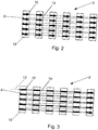
- Fig. 2 illustrates the prior art by way of example, in which six parallel and equidistant rectangles 15 are to engrave.
- each item is in Fig. 2 and Fig. 3 provided only once with a reference numeral.
- a first line is subdivided into six engraving sections 12 and five branches 13.
- the material of the printing plate 1 is removed by the laser beam 4.
- the jumps 13 is the laser 2 shut off.
- ten transitions between a engraving path 12 and a jump 13, or vice versa are necessary. In these passages, it is necessary that the movement of the mirror system 3 is first braked, the laser off, or turned on, and then the mirror system 3 is accelerated again.
- Fig. 3 illustrates the preferred embodiment of the method according to the invention with reference to the same example.
- the position at which the laser beam 4 would impinge, if it were switched on and / or not interrupted would be moved to the beginning of the first line.
- the laser 2 is activated, and the movement speed of the laser beam 4 after an initial acceleration range, which is not shown here, held substantially constant.
- the first line is divided into six engraving sections 12 and five transfer sections 14.
- the laser 2 is turned on, but the laser beam 4 is blocked by the shutter element 7, whereby the moving speed can be kept substantially constant.
- the precise and high-speed control of the shutter element 7 allows a high quality of the length of both the engraving sections 12 and the transfer sections 14 and thus the entire engraving field fifth
- continuous engraving sections 12 are generated, therefore continuous lines are removed and no dot matrix is generated.
- the mirror system 3 is moved according to a line feed between two adjacent first lines.
- flat engravings on the engraving field 5 can be generated by the laser beam 4.
- the laser beam 4 is moved several times over a first line before the page feed. As a result, 4 depth profiles can be easily generated by the laser beam.
- the line feed is selected in this way is that the engraving sections 12 of the adjacent first lines overlap at least partially. This will be used for intaglio intaglio printing in achieved advantageously coherent ablated areas with smooth structure of the gravure floor.
- the line feed is superimposed on a return movement 8 via the engraving field 5, and the movement of the laser beam 2 is rectified in each first line.
- a high quality of the engraving can be achieved, since the conditions for each first line are the same and therefore no dislocations of the individual engraving sections 12 occur.
- the movement of the laser beam 4 is directed in opposite directions. This eliminates a return movement 8, whereby the time duration for the process can be further reduced.
- the initial acceleration range and the end deceleration range are arranged outside the engraving field 5.
- the shutter element 7 is only required for interrupting the laser beam 4, whereby the complexity of the device is reduced and the quality of the engraving is increased.
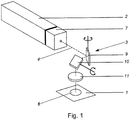
- FIG. 1 A preferred embodiment of a device with which the method can be carried out is in Fig. 1 shown.
- This preferred embodiment comprises a laser 2 with a shutter element 7 arranged directly in front of it.
- the mirror system 3 comprises a first mirror 9 which is movable such that the laser beam can be deflected in a predeterminable manner in a first direction, and a second mirror 10 which is movable in this way in that the laser beam can be deflected in a predeterminable manner in a second direction substantially orthogonal to the first direction.
- the device of the preferred embodiment comprises a focusing lens 11.
- the laser beam 4 can be focused on the printing plate 1, wherein the diameter of the laser beam 4 is preferably selected in the range between 40 microns and 20 microns.
- the width of the region removed by the laser beam 4 along an engraving path 12 can essentially correspond to the diameter of the laser beam 4.
- the width of this worn Range is often referred to as track width.
- the track width can be reduced by the choice of the diameter of the laser beam 4 or by reducing the wavelength of the laser 2, for example by frequency doubling, or else by choosing a different material of the printing plate.
- the material of the printing plate 1 is removed by the laser beam 4 to a depth of 10 .mu.m to 200 .mu.m.
- the output power of the laser 2 is preferably chosen to be an output power of more than 10 W, in particular more than 40 W.
- a pulse laser is used as laser 2.
- Such pulse lasers do not emit the laser beam 4 continuously, but in the form of periodically recurring short pulses, the instantaneous output power of the laser 2 being a multiple of the time-averaged output power of the laser 2 during the pulse. As a result, a targeted removal of material of the printing plate 1, without unduly large thermal stress on the printing plate 1 can be achieved.
- the duration of a pulse of a pulse laser is referred to as the pulse duration.
- the frequency with which the pulses of a pulse laser recur periodically is called the repetition rate.
- ultrashort pulse lasers are pulse lasers whose pulse duration is in the range of picoseconds, femtoseconds or attoseconds. Such a ultrashort pulse laser may, for example, have a pulse duration of a few picoseconds. Due to this short pulse duration, and the high output power during a pulse of the ultrashort pulse laser, there is essentially a punctual removal of material from the printing plate 1 without melting or evaporating adjacent areas.
- the movement speed in the range of 0.5 m / s to 10 m / s, preferably in the range of 1 m / s to 6 m / s, in particular in the range of 2 m / s to 5 m / s , is elected.
- the engraving of the printing plate 1 can be done quickly.
- a laser 2 designed as a pulsed laser is used together with a shutter element 7, since the pulses of the laser 2 and the shutter element 7 are not necessarily synchronized, the problem may arise that at a transition from transfer path 14 to engraving path 12, the shutter element 7 Although it is opened according to the template, the position at which the laser beam 4 impinges on the printing plate 1 but would continue to move a certain distance before the first pulse of the laser 2 begins, which can remove the material of the printing plate 1, whereby the exact point from which the material is removed only within a certain range of variation can be specified.
- an analogous problem occurs.
- an edge area of an engraved line is frayed. The size of the frayed edge region therefore depends on the repetition rate of the laser 2 and the movement speed of the laser beam 4 on the printing plate 1.
- the repetition rate of the laser 2 is chosen greater than 0.5 MHz.
- the repetition rate of the laser 2 is chosen greater than 0.5 MHz.
- an engraving of the printing plate 1 with good quality can be achieved even at higher movement speeds of the laser beam 4 via the pressure plate 1. Due to the high repetition rate and the resulting small spatial distance between two pulses, a continuous line can be removed. Furthermore, this allows a high quality of the engraving with respect to the formation of the edges can be achieved.
- a movement speed of, for example, 2 m / s and a repetition rate of 1 Mhz with a diameter of the Laser beam 4, for example, 25 microns, two laser pulses at a distance of 2 microns to each other and overlap so strong.
- the moving speed is set equal to the product of a reference engraving line width, a repetition rate of the laser 2 and an edge tolerance value.
- a specifiable good quality of the engraving can be achieved, which can be determined in particular by the margin tolerance value.
- This edge tolerance value is in this case that value which may be the ratio of the width of a frayed edge region to the reference engraving line width. Furthermore, this allows the speed of movement to be selected so high that the specifiable quality is just reached, whereby the duration of the engraving process can be kept low.
- the reference engraving line width is the width of a region to be ablated, the first lines in which the laser 2 removes the material being arranged normal to that line, and the reference engraving line width being in the characteristic range of the width of the lines passing through the line Template are given.
- the reference engraving line width is selected in the range from 20 ⁇ m to 200 ⁇ m, preferably in the range from 50 ⁇ m to 150 ⁇ m. These areas correspond to the typical width of lines, such as those used in the engraving of printing plates 1 for intaglio intaglio printing of security documents, in particular banknotes or stamps.
- the marginal tolerance value is chosen to be less than 5%, preferably less than 3%, in particular less than 1.5%. This allows the quality of the engraving to be adapted to the corresponding specifications.
- the user has an ultra-short pulse laser with a repetition rate of 1 MHz available, with which he should create an engraving whose lines a typical Width of 100 microns, which is why the user chooses a reference engraving line width of 100 microns. Due to the quality requirement, an edge tolerance value of 2% is selected. Therefore, in this example, the user will select a moving speed of 2 m / s, which will achieve the maximum moving speed which still meets the quality requirements, and therefore the duration in which the printing plate 1 is engraved is kept as low as possible. If higher quality standards are required in selected engraving fields 5, or if significantly narrower lines are to be engraved, the speed of movement in these engraving fields 5 can be reduced.
- the laser beam 4 is moved across the engraving field 5 for the removal of another layer in parallel further lines, wherein the movement speed of the laser beam 4 in each further line is kept approximately constant after an initial acceleration range up to a final deceleration range, and by means of the shutter element 7, the impact of the laser beam 4 is controlled on the engraving area 6, wherein the other lines are rotated relative to the first lines.
- the orientation of the parallel tracks of the first lines and / or of the second lines is less easily recognizable, as a result of which the quality of the engraving can advantageously be further improved.
- the further lines being twisted in relation to the first lines, the frayed edge region of an engraved line can be less pronounced, since the shape of the edge region depends on the direction of the parallel parts of a layer.
- parallel further lines of the second layer may have an approx 90 ° angle to the parallel first lines of the first layer.
- a plurality of first layers and further layers can be removed one behind the other until the desired depth of the removed regions has been reached.
- the angle with which the further lines are rotated relative to the first lines is selected such that a predeterminable plurality of layers, in particular at least ten, can be removed before the further lines again essentially parallel to the first lines are. This allows a particularly smooth bottom of the engraving can be achieved.
- an angle between 60 ° and 120 ° is selected for the angle at which the further lines are rotated relative to the first lines.
- the parallel first first row of the first layer and the second parallel row of a second layer include an angle of 100 °, and the parallel first rows of the first layer and the parallel third rows of a third layer an angle of 200 °.
- Each further layer is correspondingly rotated by a further 100 °.
- the first lines of the first layer are only substantially parallel with the lines of the eighteenth layer.
- a first vector graphic is generated for the first layer, wherein the vectors of the vector graphic are straight and parallel and the direction of the vectors corresponds to the orientation of the first lines.
- the first layer can be removed according to the first vector graphic.
- a first line comprises a jump vector, for the jump, and a single continuous vector for the at least one engraving section 12 and / or at least one transfer section 13.
- a further vector graphic is generated from parallel, even vectors, the direction of the vectors corresponding to the orientation of the lines of the respective layer.
- the further layers can be removed according to the further vector graphics.
- the laser beam 4 along the engraving section 12 is attenuated by the shutter element 7 as a function of a template so that it is not completely blocked.
- continuously running height profiles of the engraving can be created, and / or particularly fine lines can be created.
- special designs, in particular for blind embossing, can be realized, whereby the security of the security document can be further increased.
- the individual vectors of the vector graphics are provided with an associated parameter, wherein the attenuation of the laser beam 4 by the shutter element 7 is specified by the parameter.
- This parameter can be displayed as a gray value or as a line width of the single vector.
Description
Die Erfindung betrifft ein Verfahren zum Gravieren einer Druckplatte für den Intaglio-Stichtiefdruck gemäß dem Oberbegriff des Patentanspruches 1.The invention relates to a method for engraving a printing plate for Intaglio intaglio printing according to the preamble of
Ein derartiges Verfahren ist bekannt, bei welchem ein Laserstrahl mittels beweglichen Spiegel über eine zu gravierende Druckplatte geführt wird. Der Verlauf der Bewegung des Laserstrahls unterteilt sich hierbei in Gravurstrecken, bei welchen das Material der Druckplatte vom Laserstrahl abgetragen wird, und in Sprüngen, bei welchen der Laser abgeschaltet ist.Such a method is known, in which a laser beam is guided by means of movable mirrors over a printing plate to be engraved. The course of the movement of the laser beam is divided here into engraving sections, in which the material of the printing plate is removed by the laser beam, and in jumps, in which the laser is switched off.
Nachteilig an diesem Verfahren ist allerdings, dass die Gravur einer Druckplatte sehr lange dauert.A disadvantage of this method, however, is that the engraving of a printing plate takes a very long time.
Aus der
Aufgabe der Erfindung ist es daher ein Verfahren der eingangs genannten Art anzugeben, mit welchem die genannten Nachteile vermieden werden können, mit welchem ein schnelles Gravieren von Druckplatten bei gleichzeitig guter Qualität möglich ist.The object of the invention is therefore to provide a method of the type mentioned, with which the mentioned disadvantages can be avoided, with which a fast engraving of printing plates at the same time good quality is possible.
Erfindungsgemäß wird dies durch die Merkmale des Patentanspruches 1 erreicht.This is achieved by the features of
Dadurch ergibt sich der Vorteil, dass die Gravurdauer durch den Wegfall der Brems-und Beschleunigungsvorgänge sowie durch die Wartezeiten nach Sprüngen - auf Grund der masseverzögerten Reaktion des Spiegelsystems - deutlich reduziert werden kann. Weiters ergibt sich dadurch der Vorteil, dass eine gute Qualität der Gravur der Druckplatte gewährleistet werden kann, da der Laser im Wesentlichen im Dauerbetrieb betrieben werden kann, wodurch auch die Ausgangsleistung des Lasers im Wesentlichen konstant gehalten werden kann.This results in the advantage that the engraving time can be significantly reduced by the elimination of the braking and acceleration processes as well as by the waiting times for jumps - due to the mass-delayed reaction of the mirror system. Furthermore, this results in the advantage that a good quality of the engraving of the printing plate can be ensured, since the laser can be operated substantially in continuous operation, whereby the output power of the laser can be kept substantially constant.
Die Unteransprüche betreffen weitere vorteilhafte Ausgestaltungen der Erfindung.The subclaims relate to further advantageous embodiments of the invention.
Ausdrücklich wird hiermit auf den Wortlaut der Ansprüche Bezug genommen, wodurch die Ansprüche an dieser Stelle durch Bezugnahme in die Beschreibung eingefügt sind und als wörtlich wiedergegeben gelten.It is expressly referred to the wording of the claims, whereby the claims are hereby incorporated by reference into the description and are considered to be reproduced verbatim.
Die Erfindung wird unter Bezugnahme auf die beigeschlossenen Zeichnungen, in welchen lediglich bevorzugte Ausführungsformen beispielhaft dargestellt sind, näher beschrieben. Dabei zeigt:
-
Fig. 1 eine Skizze einer bevorzugten Ausführungsform einer Vorrichtung zur Durchführung des Verfahrens; -
Fig. 2 eine Prinzipdarstellung des Verfahrens gemäß dem Stand der Technik; und -
Fig. 3 eine Prinzipdarstellung einer bevorzugten Ausführungsform des erfindungsgemäßen Verfahrens.
-
Fig. 1 a sketch of a preferred embodiment of an apparatus for performing the method; -
Fig. 2 a schematic representation of the method according to the prior art; and -
Fig. 3 a schematic representation of a preferred embodiment of the method according to the invention.
Die
Der Intaglio-Stichtiefdruck , ist ein Druckverfahren zum Drucken mit einer gravierten Druckplatte 1, wobei die Form der Gravur nicht nur als Farbe auf die zu bedruckenden Bögen aufgetragen wird, sondern es auch zu einer nachhaltigen und oft auch tastbaren plastischen Verformung der bedruckten Bögen kommt, weshalb der Intaglio-Stichtiefdruck oft als Sicherheitsmerkmal für Sicherheitsdokumente wie beispielsweise Banknoten, Briefmarken oder Wertpapieren verwendet wird.Intaglio intaglio printing is a printing process for printing with an engraved
Beim Verfahren zum Gravieren einer Druckplatte 1 wird das Spiegelsystem 3 derart bewegt, dass der Laserstrahl 4 des Lasers 2 bei dem Abtrag einer ersten Schicht in im Wesentlichen parallelen ersten Zeilen über ein Gravurfeld 5 bewegt wird, wobei die Bewegungsgeschwindigkeit des Laserstrahls 4 in jeder ersten Zeile nach einem Anfangsbeschleunigungsbereich bis zu einem Endverzögerungsbereich annähernd konstant gehalten wird. Dadurch kann die Zahl der Brems- und Beschleunigungsvorgänge des Spiegelsystems 3, sowie der Wartezeiten nach Sprüngen 13 in vorteilhafter Weise gering gehalten werden.In the method for engraving a
Die Bewegungsgeschwindigkeit des Laserstrahls 4 ist jene Geschwindigkeit, mit welcher der Laserstrahls 4 die Druckplatte 1 überstreicht.The moving speed of the
Der Anfangsbeschleunigungsbereich ist dabei jener Bereich, den der Laserstrahl 4 bei dem Beschleunigungsvorgang des Spiegelsystems 3 überstreicht, oder, wenn der Laserstrahl 4 unterbrochen wird, überstreichen würde.The initial acceleration range is that range which the
Analog ist der Endverzögerungsbereich jener Bereich, den der Laserstrahl 4 bei dem Bremsvorgang des Spiegelsystems 3 überstreicht, oder, wenn der Laserstrahl 4 unterbrochen wird, überstreichen würde.Similarly, the end deceleration range is that range which the
Die Wartezeiten nach Sprüngen sind jene Zeiten, welche bei einem Sprung 13 durch die masseverzögerte Reaktion des Spiegelsystems 3 verursacht werden.The waiting times after jumps are those times which are caused by the mass-delayed reaction of the
Vorgesehen ist, dass mittels eines Shutterelementes 7 das Auftreffen des Laserstrahls 4 auf einem Gravurbereich 6 in Abhängigkeit einer Vorlage geregelt wird. Dadurch kann eine gezielte Gravur der Druckplatte 1 in Abhängigkeit der Vorlage auch bei konstanter Bewegungsgeschwindigkeit des Laserstrahls 4 erfolgen. Da der Laser dadurch im Wesentlichen im Dauerbetrieb betrieben werden kann, ist auch die Ausgangsleistung des Lasers im Wesentlichen konstant. Durch den im Wesentlichen Dauerbetrieb des Lasers 2 können unerwünschte Einschalteffekte vermieden werden, was zur hohen Qualität der Gravur der Druckplatte 1 beiträgt.It is provided that by means of a
Insbesondere kann vorgesehen sein, dass die Druckplatte 1 zur Herstellung eines Sicherheitsdokumentes verwendet wird, da dadurch zuverlässig Sicherheitsmerkmale in hoher Qualität auf das Sicherheitsdokument aufgeprägt werden können.In particular, it can be provided that the
Besonders bevorzugt kann vorgesehen sein, dass direkt eine Druckplatte 1 bestehend aus Metall, insbesondere Messing, vom Laserstrahl 4 graviert wird. Direkt graviert bedeutet in dem Zusammenhang, dass nicht zunächst ein sogenannter Master aus einem wenig stabilen Material wie Kunststoffen graviert, und von diesem Master die endgültige Druckplatte 1 abgeformt wird, sondern die zum Drucken vorgesehene Druckplatte 1 direkt vom Laserstrahl 4 graviert wird. Dadurch kann ein Bearbeitungsschritt bei der Herstellung der Druckplatte 1 entfallen, wobei auch die damit verbunden Fehler vermieden werden können. Messing bietet den Vorteil, dass dieses sowohl leicht zu bearbeiten ist, und gleichzeitig den hohen mechanischen Belastungen des Intaglio-Stichtiefdruckes gewachsen ist.Particularly preferably, it can be provided that a
Insbesondere kann vorgesehen sein, dass eine im Wesentlichen ebene Druckplatte 1 graviert wird. Solche ebenen Druckplatten sind besonders flexibel im Einsatz.In particular, it can be provided that a substantially
Das Shutterelement 7 ist dazu ausgebildet, den Laserstrahl 4 vorgebbar zu unterbrechen oder abzuschwächen. Solche Shutterelemente 7 können sehr hochfrequent arbeiten und dadurch den Laserstrahl 4 sehr zeitgenau, oder im Falle eines gepulsten Lasers sogar einzelne Pulse des Lasers 2 individuell manipulieren, also in Abhängigkeit einer Vorlage abschwächen oder völlig ausblenden.The
Ausgehend von einer Vorlage, nach welcher das Auftreffen des Laserstrahls 4 auf den Gravurbereich geregelt werden kann, kann dann computerunterstützt das Spiegelsystem 3 und das Shutterelement 7 angesteuert werden.Based on a template, according to which the impact of the
Der Gravurbereich 6 ist dabei jener Bereich der Druckplatte 1, welcher vom Laserstrahl 4 durch Ansteuerung des Spiegelsystems 3 gravierbar ist, ohne dass die Position der Druckplatte 1 zum Spiegelsystem 3 verändert werden muss.The
Bevorzugt kann dabei vorgesehen sein, dass die Druckplatte 1 in mehrere der Gravurbereiche 6 unterteilt wird und eine Spiegelsystemhalterung und/oder die Druckplatte 1 zwischen dem Gravieren unterschiedlicher Gravurbereiche 6 bewegt werden. Die Spiegelsystemhalterung ist dabei eine Halterung des Spiegelsystems 3, welche bewegbar ausgebildet sein kann. Dadurch kann die Druckplatte 1 auch größer als der Gravurbereich 6 sein. Weiters kann die Druckplatte 1 mehrere nicht zusammenhängende Gravurbereiche 6 umfassen.Preferably, it can be provided that the
Ein Gravurbereich 6 wiederum kann in mehrere Gravurfelder 5 unterteilt werden, wobei diese bevorzugt von gravierten Teilbereichen des Gravurbereichs 6 gebildet werden können, während ungravierte Zonen des Gravurbereiches 6 ausgespart werden können.In turn, an
Besonders bevorzugt kann vorgesehen sein, dass durchgehende Gravurstrecken 12 erzeugt werden, daher durchgehende Linien abgetragen werden und kein Punktraster erzeugt wird.Particularly preferably, it can be provided that continuous
Gemäß der bevorzugten Ausführungsform kann vorgesehen sein, dass zwischen zwei benachbarten ersten Zeilen das Spiegelsystem 3 gemäß einem Zeilenvorschub bewegt wird. Dadurch können durch den Laserstrahl 4 flächige Gravuren auf dem Gravurfeld 5 erzeugt werden.According to the preferred embodiment it can be provided that the
Es kann weiters vorgesehen sein, dass der Laserstrahl 4 vor dem Seitenvorschub mehrfach über eine erste Zeile bewegt wird. Dadurch können durch den Laserstrahl 4 Tiefenprofile einfach erzeugt werden.It can further be provided that the
Hierbei kann bevorzugt vorgesehen sein, dass der Zeilenvorschub derart gewählt wird, dass sich die Gravurstrecken 12 der benachbarten ersten Zeilen sich zumindest teilweise überlappen. Dadurch werden für den Intaglio-Stichtiefdruck in vorteilhafter Weise zusammenhängende abgetragene Bereiche mit glatter Struktur des Gravurbodens erreicht.In this case, it can preferably be provided that the line feed is selected in this way is that the
Weiters kann bevorzugt vorgesehen sein, dass dem Zeilenvorschub eine Rückstellbewegung 8 über das Gravurfeld 5 überlagert wird, und die Bewegung des Laserstrahls 2 in jeder ersten Zeile gleichgerichtet erfolgt. Dadurch kann eine hohe Qualität der Gravur erreicht werden, da die Bedingungen für jede erste Zeile gleich sind und es daher zu keinen Versetzungen der einzelnen Gravurstrecken 12 kommt.Furthermore, it can preferably be provided that the line feed is superimposed on a
Alternativ kann vorgesehen sein, dass in direkt benachbarten ersten Zeilen die Bewegung des Laserstrahls 4 entgegengesetzt gerichtet erfolgt. Dadurch entfällt eine Rückstellbewegung 8, wodurch die Zeitdauer für das Verfahren weiter verringert werden kann.Alternatively it can be provided that in directly adjacent first lines, the movement of the
Weiters kann bevorzugt vorgesehen sein, dass der Anfangsbeschleunigungsbereich und der Endverzögerungsbereich außerhalb des Gravurfeldes 5 angeordnet werden. Dadurch wird das Shutterelement 7 nur zur Unterbrechung des Laserstrahls 4 benötigt, wodurch die Komplexität der Vorrichtung verringert und die Qualität der Gravur erhöht wird.Furthermore, it can preferably be provided that the initial acceleration range and the end deceleration range are arranged outside the
Eine bevorzugte Ausführungsform einer Vorrichtung mit welcher das Verfahren durchgeführt werden kann ist in
Durch die Fokussierlinse 11 kann der Laserstrahl 4 auf die Druckplatte 1 fokussiert werden, wobei der Durchmesser des Laserstrahls 4 bevorzugt im Bereich zwischen 40 µm und 20 µm gewählt wird. Die Breite des durch den Laserstrahl 4 abgetragenen Bereiches entlang einer Gravurstrecke 12 kann im Wesentlichen dem Durchmesser des Laserstrahls 4 entsprechen. Die Breite dieses abgetragenen Bereiches wird oft auch als Spurbreite bezeichnet. Für spezielle Applikationen kann durch die Wahl des Durchmessers des Laserstrahls 4 oder durch Verringerung der Wellenlänge des Lasers 2, etwa durch Frequenzverdoppelung, oder aber auch durch die Wahl eines anderen Materials der Druckplatte die Spurbreite reduziert werden. Bevorzugt wird das Material der Druckplatte 1 vom Laserstrahl 4 bis zu einer Tiefe von 10 µm bis 200 µm abgetragen.By the focusing
Als Ausgangsleistung des Lasers 2 wird bevorzugt eine Ausgangsleistung von über 10 W, insbesondere über 40 W gewählt.The output power of the
Beim Verfahren wird als Laser 2 ein Pulslaser verwendet.In the method, a pulse laser is used as
Solche Pulslaser senden den Laserstrahl 4 nicht kontinuierlich aus, sondern in Form von periodisch wiederkehrenden kurzen Pulsen, wobei die momentane Ausgangsleistung des Lasers 2 während des Pulses ein Vielfaches der zeitlich gemittelten Ausgangsleistung des Lasers 2 ist. Dadurch kann eine gezielte Abtragung von Material der Druckplatte 1, ohne ungebührend großen thermischen Beanspruchung der Druckplatte 1 erreicht werden.Such pulse lasers do not emit the
Hierbei wird die zeitliche Dauer eines Pulses eines Pulslasers als Pulsdauer bezeichnet. Die Frequenz, mit welcher die Pulse eines Pulslasers periodisch wiederkehren, wird als Repetitionsrate bezeichnet.In this case, the duration of a pulse of a pulse laser is referred to as the pulse duration. The frequency with which the pulses of a pulse laser recur periodically is called the repetition rate.
Besonders bevorzugt kann vorgesehen sein, dass als Laser 2 ein Ultrakurzpulslaser verwendet wird. Als Ultrakurzpulslaser werden Pulslaser bezeichnet, deren Pulsdauer sich im Bereich von Picosekunden, Femtosekunden oder Attosekunden befindet. Ein solcher Ultrakurzpulslaser kann beispielsweise eine Pulsdauer von einigen Picosekunden haben. Durch diese kurze Pulsdauer, und der hohen Ausgangsleistung während eines Pulses des Ultrakurzpulslasers, kommt es im Wesentlichen zu einem punktuellen Abtrag von Material der Druckplatte 1, ohne dass benachbarte Bereiche aufgeschmolzen oder verdampft werden. Dadurch entfällt die Bildung von Graten um die abgetragenen Bereiche der Druckplatte 1, wodurch eine aufwendige, und sich auf die Qualität der Gravur negativ auswirkende, Nachbehandlung der Druckplatte 1, beispielsweise mittels Chemikalien oder Polieren, entfallen kann. Weiters hat sich herausgestellt, dass durch die Verwendung eines Ultrakurzpulslaser die Flanken der abgetragenen Bereiche in vorteilhafter Weise wesentlich steiler ausgebildet werden können. Darüber hinaus ergibt sich ein stabiler Laserbetrieb, da der Laser 2 kontinuierlich Pulse emittiert, deren Auftreffen auf die Druckplatte 1 aber je nach Verlage geregelt wird.Particularly preferably, it can be provided that an ultrashort pulse laser is used as the
Bevorzugt kann vorgesehen sein, dass die Bewegungsgeschwindigkeit im Bereich von 0,5 m/s bis 10 m/s, vorzugsweise im Bereich von 1 m/s bis 6 m/s, insbesondere im Bereich von 2 m/s bis 5 m/s, gewählt wird. Dadurch kann die Gravur der Druckplatte 1 schnell erfolgen.It can preferably be provided that the movement speed in the range of 0.5 m / s to 10 m / s, preferably in the range of 1 m / s to 6 m / s, in particular in the range of 2 m / s to 5 m / s , is elected. As a result, the engraving of the
Wenn ein als Pulslaser ausgebildeter Laser 2 mit einem Shutterelement 7 gemeinsam verwendet wird, kann, da die Pulse des Laser 2 und das Shutterelement 7 nicht notwendigerweise synchronisiert sind, das Problem auftreten, dass an einem Übergang von Transferstrecke 14 zu Gravurstrecke 12, das Shutterelement 7 zwar gemäß der Vorlage geöffnet wird, die Position an welcher der Laserstrahl 4 auf die Druckplatte 1 auftreffen würde sich aber noch eine gewisse Strecke weiterbewegt, bevor der erste Puls des Lasers 2 einsetzt, welcher das Material der Druckplatte 1 abtragen kann, wodurch der exakte Punkt ab welchen das Material abgetragen wird nur innerhalb einer gewissen Schwankungsbreite vorgegeben werden kann. Beim Übergang von Gravurstrecke 12 zu Transferstrecke 14 tritt ein analoges Problem auf. Dadurch wird ein Randbereich einer gravierten Linie ausgefranst. Die Größe des ausgefransten Randbereiches hängt daher von der Repetitionsrate des Lasers 2 und der Bewegungsgeschwindigkeit des Laserstrahls 4 auf der Druckplatte 1 ab.If a
Besonders bevorzugt kann vorgesehen sein, dass die Repetitionsrate des Lasers 2 größer als 0,5 MHz gewählt wird. Bei einer derart hohen Repetitionsrate des Lasers 2 kann auch bei höheren Bewegungsgeschwindigkeiten des Laserstrahls 4 über die Druckplatte 1 eine Gravur der Druckplatte 1 mit guter Qualität erreicht werden. Durch die hohe Repetitionsrate und des daraus resultierenden geringen räumlichen Abstand zwischen zwei Pulsen, kann eine durchgehende Linie abgetragen werden. Weiters kann dadurch eine hohe Qualität der Gravur bezüglich der Ausbildung der Kanten erreicht werden. Bei einer Bewegungsgeschwindigkeit von beispielsweise 2 m/s und einer Repetitionsrate von 1 Mhz liegen, bei einem Durchmesser des Laserstrahls 4 von beispielsweise 25 µm, zwei Laserpulse in einem Abstand von
2 µm zueinander und überlappen damit stark.Particularly preferably, it can be provided that the repetition rate of the
2 microns to each other and overlap so strong.
Die Bewegungsgeschwindigkeit wird gleich dem Produkt einer Referenzgravurlinienbreite, einer Repetitionsrate des Lasers 2 und einem Randtoleranzwert gewählt. Dadurch kann eine vorgebbar gute Qualität der Gravur erreicht werden, welche insbesondere durch den Randtoleranzwert bestimmt werden kann. Dieser Randtoleranzwert ist hierbei jener Wert, welcher das Verhältnis der Breite eines ausgefransten Randbereiches zur Referenzgravurlinienbreite betragen darf. Weiters kann dadurch die Bewegungsgeschwindigkeit derart hoch gewählt werden, dass die vorgebbare Qualität gerade erreicht wird, wodurch die Dauer des Gravurprozesses gering gehalten werden kann.The moving speed is set equal to the product of a reference engraving line width, a repetition rate of the
Die Referenzgravurlinienbreite ist die Breite eines als Linie ausgebildeten abzutragenden Bereiches, wobei die ersten Zeilen, in welchen der Laser 2 das Material abträgt, normal zu dieser Linie angeordnet sind, und wobei sich die Referenzgravurlinienbreite im charakteristischen Bereich der Breite der Linien befindet, welche durch die Vorlage vorgegebenen sind.The reference engraving line width is the width of a region to be ablated, the first lines in which the
Bevorzugt kann vorgesehen sein, dass die Referenzgravurlinienbreite im Bereich von 20 µm bis 200 µm, vorzugsweise im Bereich von 50 µm bis 150 µm gewählt wird. Diese Bereiche entsprechen den typischen Breite von Linien, wie sie bei der Gravur von Druckplatten 1 für den Intaglio-Stichtiefdruck von Sicherheitsdokumenten, insbesondere Banknoten oder Briefmarken verwendet werden.It can preferably be provided that the reference engraving line width is selected in the range from 20 μm to 200 μm, preferably in the range from 50 μm to 150 μm. These areas correspond to the typical width of lines, such as those used in the engraving of
Bevorzugt kann weiters vorgesehen sein, dass der Randtoleranzwert kleiner 5 %, vorzugsweise kleiner 3 %, insbesondere kleiner 1,5 % gewählt wird. Dadurch kann die Qualität der Gravur an die entsprechenden Vorgaben angepasst werden.Preferably, it may further be provided that the marginal tolerance value is chosen to be less than 5%, preferably less than 3%, in particular less than 1.5%. This allows the quality of the engraving to be adapted to the corresponding specifications.
Gemäß einem konkreten Beispiel, welches hier nur zum Zwecke der Anschaulichkeit dient und keineswegs den Schutzbereich einschränken soll, stehen dem Benützer ein Ultrakurzpulslaser mit einer Repetitionsrate von 1 MHz zur Verfügung, mit welchen er eine Gravur erstellen soll, deren Linien eine typische Breite von 100 µm haben, weshalb der Benützer eine Referenzgravurlinienbreite von 100 µm wählt. Aufgrund der Qualitätsanforderung wird ein Randtoleranzwert von 2 % gewählt. Daher wird der Benützer in diesem Beispiel eine Bewegungsgeschwindigkeit von 2 m/s wählen, wodurch die maximale Bewegungsgeschwindigkeit welche noch den Qualitätsanforderungen entspricht erzielt wird, und daher der Dauer, in welcher die Druckplatte 1 graviert wird, so gering wie möglich gehalten wird. Sind in ausgewählten Gravurfelder 5 höhere Qualitätsansprüche notwendig, oder sollen deutlich schmalere Linien graviert werden, so kann in diesen Gravurfeldern 5 die Bewegungsgeschwindigkeit reduziert werden.According to a concrete example, which serves here only for the sake of clarity and is not intended to limit the scope of protection, the user has an ultra-short pulse laser with a repetition rate of 1 MHz available, with which he should create an engraving whose lines a typical Width of 100 microns, which is why the user chooses a reference engraving line width of 100 microns. Due to the quality requirement, an edge tolerance value of 2% is selected. Therefore, in this example, the user will select a moving speed of 2 m / s, which will achieve the maximum moving speed which still meets the quality requirements, and therefore the duration in which the
Es kann vorgesehen sein, dass mehrere Schichten in parallelen ersten Zeilen abgetragen werden, bis die gewünschte Tiefe der abgetragenen Bereiche erreicht ist.It can be provided that several layers are removed in parallel first rows until the desired depth of the removed areas is reached.
Hierbei kann bevorzugt vorgesehen sein, dass durch den Laserstrahl 4 solange Schichten abgetragen werden, bis die gewünschte Tiefe der abgetragenen Bereiche erreicht ist.In this case, it can preferably be provided that layers are removed by the
Weiters kann bevorzugt vorgesehen sein, dass der Laserstrahl 4 zum Abtrag einer weiteren Schicht in parallelen weiteren Zeilen über das Gravurfeld 5 bewegt wird, wobei die Bewegungsgeschwindigkeit des Laserstrahls 4 in jeder weiteren Zeile nach einem Anfangsbeschleunigungsbereich bis zu einem Endverzögerungsbereich annähernd konstant gehalten wird, und dass mittels des Shutterelementes 7 das Auftreffen des Laserstrahls 4 auf dem Gravurbereich 6 geregelt wird, wobei die weiteren Zeilen gegenüber den ersten Zeilen verdreht sind. Durch die Überlagerung von relativ zueinander verdrehten Schichten ist die Orientierung der parallelen Spuren der ersten Zeilen und/oder der zweiten Zeilen weniger gut erkennbar, wodurch in vorteilhafter Weise die Qualität der Gravur weiter verbessert werden kann. Weiters kann durch die Abtragung in mehreren Schichten, wobei die weiteren Zeilen gegenüber den ersten Zeilen verdreht sind, der ausgefranste Randbereich einer gravierten Linie weniger stark ausgeprägt sein, da die Ausprägung des Randbereiches von der Richtung der parallelen Teilen einer Schicht abhängig ist.Furthermore, it can preferably be provided that the
Beispielsweise können parallelen weiteren Zeilen der zweiten Schicht einen etwa 90° Winkel zu den parallelen ersten Zeilen der ersten Schicht einschließen. Hierbei können hintereinander mehrere erste Schichten und weitere Schichten abgetragen werden, bis die gewünschte Tiefe der abgetragenen Bereiche erreicht ist.For example, parallel further lines of the second layer may have an approx 90 ° angle to the parallel first lines of the first layer. In this case, a plurality of first layers and further layers can be removed one behind the other until the desired depth of the removed regions has been reached.
Besonders bevorzugt kann vorgesehen sein, dass der Winkel, mit welchen die weiteren Zeilen gegenüber den ersten Zeilen verdreht wird, derart gewählt wird, dass eine vorgebbare Mehrzahl an Schichten, insbesondere mindestens zehn, abgetragen werden können, bevor die weiteren Zeilen wieder im Wesentlichen parallel zu den ersten Zeilen sind. Dadurch kann ein besonders glatter Boden der Gravur erreicht werden.Particularly preferably, it may be provided that the angle with which the further lines are rotated relative to the first lines is selected such that a predeterminable plurality of layers, in particular at least ten, can be removed before the further lines again essentially parallel to the first lines are. This allows a particularly smooth bottom of the engraving can be achieved.
Insbesondere kann vorgesehen sein, dass für den Winkel, mit welchen die weiteren Zeilen gegenüber den ersten Zeilen verdreht wird, ein Winkel zwischen 60° und 120° gewählt wird. Dadurch kann ein besonders gutes Ergebnis erzielt werden, auch wenn lediglich wenige Schichten abgetragen werden.In particular, it can be provided that an angle between 60 ° and 120 ° is selected for the angle at which the further lines are rotated relative to the first lines. As a result, a particularly good result can be achieved, even if only a few layers are removed.
In einem weiteren Beispiel schließen die parallelen ersten Zeilen der ersten Schicht und die parallelen zweiten Zeilen einer zweiten Schicht einen Winkel von 100°, und die parallelen ersten Zeilen der ersten Schicht und die parallelen dritten Zeilen einer dritten Schicht einen Winkel von 200° ein. Jede weiter Schicht wird entsprechend um weitere 100° verdreht. Hierbei sind die ersten Zeilen der ersten Schicht erst mit den Zeilen der achtzehnten Schicht im wesentlichen parallel. Auch hier können bevorzugt so viele Schichten hintereinander abgetragen werden, bis die gewünschte Tiefe der abgetragenen Bereiche erreicht ist.In another example, the parallel first first row of the first layer and the second parallel row of a second layer include an angle of 100 °, and the parallel first rows of the first layer and the parallel third rows of a third layer an angle of 200 °. Each further layer is correspondingly rotated by a further 100 °. Here, the first lines of the first layer are only substantially parallel with the lines of the eighteenth layer. Here as well, it is preferable to remove so many layers in succession until the desired depth of the removed regions has been reached.
Bevorzugt kann vorgesehen sein, dass ausgehend von der Vorlage, welche graviert werden soll, für die erste Schicht eine erste Vektorgrafik erzeugt wird, wobei die Vektoren der Vektorgrafik gerade und parallel sind und die Richtung der Vektoren der Ausrichtung der ersten Zeilen entspricht. Die erste Schicht kann gemäß der ersten Vektorgrafik abgetragen werden.It can preferably be provided that, starting from the template which is to be engraved, a first vector graphic is generated for the first layer, wherein the vectors of the vector graphic are straight and parallel and the direction of the vectors corresponds to the orientation of the first lines. The first layer can be removed according to the first vector graphic.
Besonders bevorzugt kann vorgesehen sein, dass eine erste Zeile einen Sprungvektor, für den Sprung, sowie einen einzigen durchgehenden Vektor für die wenigstens eine Gravurstrecke 12 und/oder wenigstens eine Transferstrecke 13 umfasst. Dadurch kann die Druckplatte 1 besonders schnell und effizient graviert werden. Weiters kann dadurch eine besonders gute Qualität der Gravur erreicht werden, wenn der Laserstrahl 4 mit im Wesentlichen konstanter Bewegungsgeschwindigkeit über die Druckplatte 1 bewegt wird. Weiters kann der Rechenaufwand dadurch gering gehalten werden.Particularly preferably, it can be provided that a first line comprises a jump vector, for the jump, and a single continuous vector for the at least one
Weiters kann vorgesehen sein, dass für jede weitere, insbesondere zur ersten Schicht verdrehten, Schicht eine weitere Vektorgrafik aus parallelen, geraden Vektoren erzeugt wird, wobei die Richtung der Vektoren der Ausrichtung der Zeilen der jeweiligen Schicht entspricht. Die weiteren Schichten können gemäß der weiteren Vektorgrafiken abgetragen werden.Furthermore, it can be provided that for each additional layer, in particular twisted to the first layer, a further vector graphic is generated from parallel, even vectors, the direction of the vectors corresponding to the orientation of the lines of the respective layer. The further layers can be removed according to the further vector graphics.
Weiters kann bevorzugt vorgesehen sein, dass der Laserstrahl 4 entlang der Gravurstrecke 12 vom Shutterelement 7 in Abhängigkeit einer Vorlage vorgebbar abgeschwächt wird, daher nicht vollständig blockiert wird. Dadurch können kontinuierlich verlaufende Höhenprofile der Gravur erstellt werden, und/oder besonders feine Linien erstellt werden. Dadurch können besondere Designs, insbesondere für Blindprägungen, realisiert werden, wodurch die Sicherheit des Sicherheitsdokumentes weiters erhöht werden kann.Furthermore, it can preferably be provided that the
Insbesondere kann vorgesehen sein, dass die einzelnen Vektoren der Vektorgrafik mit einem zugeordneten Parameter versehen werden, wobei die Abschwächung des Laserstrahls 4 durch das Shutterelement 7 vom Parameter vorgegeben wird. Dieser Parameter kann als Grauwert oder als Linienbreite des einzelnen Vektors dargestellt werden.In particular, it can be provided that the individual vectors of the vector graphics are provided with an associated parameter, wherein the attenuation of the
Claims (15)
- A method for engraving a printing plate (1) for intaglio line gravure printing, comprising a laser (2) and a mirror system (3) interacting with the laser (2), wherein gravure paths (12) are removed continuously by the laser beam (4), characterized in that the mirror system (3) is moved in such a way that the laser beam (4) of the laser (2), when a first layer is removed, is moved in substantially parallel first lines over a gravure field (5), wherein the movement velocity of the laser beam (4) is kept approximately constant in each first line after an initial acceleration region up to a final deceleration region, that by means of a shutter element (7) the impingement of the laser beam (4) on an engraved region (6) is controlled depending on a template, that a pulse laser is used as a laser (2), and that the movement velocity is selected equal to the product of a reference gravure line width, a repetition rate of the laser (2) and a boundary tolerance value.
- A method according to claim 1, characterized in that a printing plate (1) consisting of a metal, especially brass, is directly engraved by the laser beam (4).
- A method according to one of the claims 1 or 2, characterized in that a substantially flat printing plate (1) is engraved.
- A method according to one of the claims 1 to 3, characterized in that an ultrashort pulse laser is used as a laser (2).
- A method according to one of the claims 1 to 4, characterized in that the repetition rate of the laser (2) is selected greater than 0.5 MHz.
- A method according to claim 5, characterized in that the boundary tolerance value is selected less than 5%, preferably less than 3%, especially less than 1.5%, and the reference gravure line width is especially selected in the range of 20 µm to 200 µm, preferably in the range of 50 µm to 150 µm.
- A method according to one of the claims 1 to 6, characterized in that the movement velocity is selected in the range of 0.5 m/s to 10 m/s, preferably in the range of 1 m/s to 6 m/s, especially in the range of 2 m/s to 5 m/s.
- A method according to one of the claims 1 to 7, characterized in that the mirror system (3) is moved according to a line feed between two adjacent first lines, that a return movement (8) is superimposed especially on the line feed over the gravure field (5), and that especially the movement of the laser beam (2) in each first line occurs in a co-directional manner.
- A method according to one of the claims 1 to 8, characterized in that the initial acceleration region and the final deceleration region are arranged outside of the gravure field (5).
- A method according to one of the claims 1 to 9, characterized in that the laser beam (4) is moved in parallel further lines over the gravure field (5) for removing a further layer, wherein the movement velocity of the laser beam (4) in each further line is kept approximately constant after an initial acceleration region up to a final deceleration region, and that by means of the shutter element (7) the impingement of the laser beam (4) on the engraved region (6) is controlled, wherein the parallel further lines are twisted about an angle in relation to the parallel first lines.
- A method according to claim 10, characterized in that the angle with which the further lines are twisted in relation to the first lines are selected in such a way that a predeterminable plurality of layers, especially at least ten, can be removed before the further lines are again substantially parallel to the first lines.
- A method according to one of the claims 1 to 11, characterized in that the printing plate (1) is subdivided into several of the engraved regions (6), and a mirror system support and/or the printing plate (1) are moved between the engraving of different engraved regions (6).
- A method according to one of the claims 1 to 12, characterized in that the engraved region (6) is again subdivided into several gravure fields (5).
- A method according to one of the claims 1 to 13, characterized in that the laser beam (4) is weakened in a predeterminable manner along a gravure path (12) by the shutter element (7) depending on the template.
- A method for producing a security document, characterized in that a printing plate (1), which is used for producing the security document, is produced according to the method according to one of the claims 1 to 14.
Priority Applications (1)
| Application Number | Priority Date | Filing Date | Title |
|---|---|---|---|
| PL12450038T PL2561987T3 (en) | 2011-08-25 | 2012-08-24 | Method for engraving a printing plate |
Applications Claiming Priority (1)
| Application Number | Priority Date | Filing Date | Title |
|---|---|---|---|
| ATA1220/2011A AT511830B1 (en) | 2011-08-25 | 2011-08-25 | METHOD FOR ENGRAVING A PRESSURE PLATE |
Publications (3)
| Publication Number | Publication Date |
|---|---|
| EP2561987A2 EP2561987A2 (en) | 2013-02-27 |
| EP2561987A3 EP2561987A3 (en) | 2014-03-12 |
| EP2561987B1 true EP2561987B1 (en) | 2016-12-21 |
Family
ID=46799186
Family Applications (1)
| Application Number | Title | Priority Date | Filing Date |
|---|---|---|---|
| EP12450038.0A Active EP2561987B1 (en) | 2011-08-25 | 2012-08-24 | Method for engraving a printing plate |
Country Status (6)
| Country | Link |
|---|---|
| EP (1) | EP2561987B1 (en) |
| AT (1) | AT511830B1 (en) |
| ES (1) | ES2618882T3 (en) |
| HU (1) | HUE033480T2 (en) |
| PL (1) | PL2561987T3 (en) |
| PT (1) | PT2561987T (en) |
Families Citing this family (3)
| Publication number | Priority date | Publication date | Assignee | Title |
|---|---|---|---|---|
| DE102013212652B4 (en) * | 2013-06-28 | 2016-12-15 | Continental Automotive Gmbh | Device for operating a machine tool and machine tool |
| CN112192032A (en) * | 2020-09-30 | 2021-01-08 | 深圳市睿达科技有限公司 | High-speed laser uniform carving method |
| CN113478948B (en) * | 2021-07-01 | 2022-12-02 | 绍兴鑫昌印花机械科技有限公司 | Double-laser net making machine |
Family Cites Families (9)
| Publication number | Priority date | Publication date | Assignee | Title |
|---|---|---|---|---|
| CH612376A5 (en) * | 1976-03-10 | 1979-07-31 | Lasag Ag | Apparatus for scribing printing formes using laser beams, and method for operating this apparatus |
| US4131782A (en) * | 1976-05-03 | 1978-12-26 | Lasag Ag | Method of and apparatus for machining large numbers of holes of precisely controlled size by coherent radiation |
| ATE282526T1 (en) * | 2001-05-25 | 2004-12-15 | Stork Prints Austria Gmbh | METHOD AND DEVICE FOR PRODUCING A PRINTING FORM |
| ITMC20020011A1 (en) * | 2002-02-06 | 2003-08-06 | Tech Epikos Srl | METHOD AND RELATED SYSTEM FOR LASER ENGRAVING OF SLABS OR CYLINDRICALCOGRAPHS. |
| US7126619B2 (en) * | 2002-05-31 | 2006-10-24 | Buzz Sales Company, Inc. | System and method for direct laser engraving of images onto a printing substrate |
| AT504185B1 (en) * | 2003-07-03 | 2009-06-15 | Oebs Gmbh | METHOD FOR PRODUCING A PRESSURE PLATE |
| DE202004011832U1 (en) * | 2004-07-28 | 2004-11-04 | Lambda Physik Ag | Light beam blocking system for machining laser with synchronized triggering uses chopper disk with opaque sectors and laser trigger pulses may be synchronized with rotation of disk |
| DE102007044653A1 (en) * | 2007-09-18 | 2009-03-19 | Hell Gravure Systems Gmbh & Co. Kg | Direct laser engraving of metal sheet on metal carrier, for rotogravure printing, employs sheet made from surface-treated copper or brass alloy |
| DE102008032618A1 (en) * | 2008-07-11 | 2010-01-14 | Wetzel Gmbh | Short-pulse laser engraving process and assembly to emboss the surface of aircraft skin panel with drag-reduction finish |
-
2011
- 2011-08-25 AT ATA1220/2011A patent/AT511830B1/en active
-
2012
- 2012-08-24 ES ES12450038.0T patent/ES2618882T3/en active Active
- 2012-08-24 EP EP12450038.0A patent/EP2561987B1/en active Active
- 2012-08-24 PT PT124500380T patent/PT2561987T/en unknown
- 2012-08-24 HU HUE12450038A patent/HUE033480T2/en unknown
- 2012-08-24 PL PL12450038T patent/PL2561987T3/en unknown
Also Published As
| Publication number | Publication date |
|---|---|
| EP2561987A2 (en) | 2013-02-27 |
| EP2561987A3 (en) | 2014-03-12 |
| PL2561987T3 (en) | 2017-06-30 |
| ES2618882T3 (en) | 2017-06-22 |
| PT2561987T (en) | 2017-03-28 |
| HUE033480T2 (en) | 2017-12-28 |
| AT511830B1 (en) | 2013-03-15 |
| AT511830A4 (en) | 2013-03-15 |
Similar Documents
| Publication | Publication Date | Title |
|---|---|---|
| EP3592500B1 (en) | Process for manufacturing a recess in a material by means of electromagnetic radiation and subsequent etching process | |
| EP3854513B1 (en) | Asymmetric optical beam forming system | |
| DE102014116958B4 (en) | Optical system for beam shaping of a laser beam, laser processing system, method for material processing and use of a common elongated focus zone for laser material processing | |
| WO2007012215A1 (en) | Method and device for the defined structuring of a surface with a laser unit | |
| DE202012012732U1 (en) | Steel embossing roller with a structured surface and device for producing the structured surface | |
| EP3877112B1 (en) | Method for structuring a roller surface | |
| DE102015200264A1 (en) | A method for selectively patterning a fibrous coating material for interior elements of a motor vehicle and interior element of such a coating material | |
| EP2561987B1 (en) | Method for engraving a printing plate | |
| DE102019103960A1 (en) | Process for polishing and smoothing a workpiece surface | |
| EP2689883A1 (en) | Procédé et dispositif de production d'une surface structurée sur un rouleau de gaufrage en acier | |
| WO2018054824A1 (en) | Apparatus for irradiating a work region with laser radiation, in particular 3-d printing apparatus | |
| DE102012217766B4 (en) | Method and apparatus for vapor pressure cutting of a metallic workpiece | |
| DE102012006558A1 (en) | Method for manufacturing flexographic printing plate using engraving machine, involves engraving depressions by direct laser engraving to form non-printing areas and engraving uneven surface profile in surface portion of raised printed area | |
| EP3015279B1 (en) | Method for producing a security element having a lenticular image | |
| DE102019135283A1 (en) | Process for laser material processing and laser processing system | |
| DE102015112151A1 (en) | Method and device for laser processing of a substrate with multiple deflection of a laser radiation | |
| EP3243669B1 (en) | Production method of a security element | |
| DE102011017080B4 (en) | Process for machining a workpiece with a laser beam | |
| EP3900944A1 (en) | Method for marking by means of laser pulses | |
| EP3599105B1 (en) | Method for producing a security feature by means of laser beams | |
| DE102010027145A1 (en) | Method for introducing an invisible weakening in a decorative layer and method for producing an airbag cover with such a weakened decorative layer | |
| EP2324949B1 (en) | Laser device for engraving print rollers | |
| EP2857138B1 (en) | Method for manufacture of an overarched microstructure | |
| EP3547221A1 (en) | Method for printing the surface of an object | |
| AT523951B1 (en) | PROCEDURE FOR ENGRAVING AN INTAGLIO GRAPHIC PLATE |
Legal Events
| Date | Code | Title | Description |
|---|---|---|---|
| PUAI | Public reference made under article 153(3) epc to a published international application that has entered the european phase |
Free format text: ORIGINAL CODE: 0009012 |
|
| AK | Designated contracting states |
Kind code of ref document: A2 Designated state(s): AL AT BE BG CH CY CZ DE DK EE ES FI FR GB GR HR HU IE IS IT LI LT LU LV MC MK MT NL NO PL PT RO RS SE SI SK SM TR |
|
| AX | Request for extension of the european patent |
Extension state: BA ME |
|
| PUAL | Search report despatched |
Free format text: ORIGINAL CODE: 0009013 |
|
| AK | Designated contracting states |
Kind code of ref document: A3 Designated state(s): AL AT BE BG CH CY CZ DE DK EE ES FI FR GB GR HR HU IE IS IT LI LT LU LV MC MK MT NL NO PL PT RO RS SE SI SK SM TR |
|
| AX | Request for extension of the european patent |
Extension state: BA ME |
|
| RIC1 | Information provided on ipc code assigned before grant |
Ipc: B41C 1/04 20060101AFI20140204BHEP Ipc: B41C 1/05 20060101ALI20140204BHEP |
|
| 17P | Request for examination filed |
Effective date: 20140912 |
|
| RAX | Requested extension states of the european patent have changed |
Extension state: ME Payment date: 20140912 Extension state: BA Payment date: 20140912 |
|
| RBV | Designated contracting states (corrected) |
Designated state(s): AL AT BE BG CH CY CZ DE DK EE ES FI FR GB GR HR HU IE IS IT LI LT LU LV MC MK MT NL NO PL PT RO RS SE SI SK SM TR |
|
| 17Q | First examination report despatched |
Effective date: 20150918 |
|
| GRAP | Despatch of communication of intention to grant a patent |
Free format text: ORIGINAL CODE: EPIDOSNIGR1 |
|
| INTG | Intention to grant announced |
Effective date: 20160809 |
|
| GRAS | Grant fee paid |
Free format text: ORIGINAL CODE: EPIDOSNIGR3 |
|
| GRAA | (expected) grant |
Free format text: ORIGINAL CODE: 0009210 |
|
| AK | Designated contracting states |
Kind code of ref document: B1 Designated state(s): AL AT BE BG CH CY CZ DE DK EE ES FI FR GB GR HR HU IE IS IT LI LT LU LV MC MK MT NL NO PL PT RO RS SE SI SK SM TR |
|
| AX | Request for extension of the european patent |
Extension state: BA ME |
|
| REG | Reference to a national code |
Ref country code: GB Ref legal event code: FG4D Free format text: NOT ENGLISH |
|
| REG | Reference to a national code |
Ref country code: CH Ref legal event code: EP |
|
| REG | Reference to a national code |
Ref country code: IE Ref legal event code: FG4D Free format text: LANGUAGE OF EP DOCUMENT: GERMAN |
|
| REG | Reference to a national code |
Ref country code: AT Ref legal event code: REF Ref document number: 855127 Country of ref document: AT Kind code of ref document: T Effective date: 20170115 |
|
| REG | Reference to a national code |
Ref country code: RO Ref legal event code: EPE |
|
| REG | Reference to a national code |
Ref country code: CH Ref legal event code: NV Representative=s name: BOVARD AG PATENT- UND MARKENANWAELTE, CH |
|
| REG | Reference to a national code |
Ref country code: DE Ref legal event code: R096 Ref document number: 502012009084 Country of ref document: DE |
|
| PG25 | Lapsed in a contracting state [announced via postgrant information from national office to epo] |
Ref country code: LV Free format text: LAPSE BECAUSE OF FAILURE TO SUBMIT A TRANSLATION OF THE DESCRIPTION OR TO PAY THE FEE WITHIN THE PRESCRIBED TIME-LIMIT Effective date: 20161221 |
|
| REG | Reference to a national code |
Ref country code: DE Ref legal event code: R082 Ref document number: 502012009084 Country of ref document: DE Representative=s name: DREISS PATENTANWAELTE PARTG MBB, DE |
|
| REG | Reference to a national code |
Ref country code: NL Ref legal event code: FP |
|
| REG | Reference to a national code |
Ref country code: SE Ref legal event code: TRGR Ref country code: PT Ref legal event code: SC4A Ref document number: 2561987 Country of ref document: PT Date of ref document: 20170328 Kind code of ref document: T Free format text: AVAILABILITY OF NATIONAL TRANSLATION Effective date: 20170320 |
|
| REG | Reference to a national code |
Ref country code: LT Ref legal event code: MG4D |
|
| PG25 | Lapsed in a contracting state [announced via postgrant information from national office to epo] |
Ref country code: LT Free format text: LAPSE BECAUSE OF FAILURE TO SUBMIT A TRANSLATION OF THE DESCRIPTION OR TO PAY THE FEE WITHIN THE PRESCRIBED TIME-LIMIT Effective date: 20161221 Ref country code: NO Free format text: LAPSE BECAUSE OF FAILURE TO SUBMIT A TRANSLATION OF THE DESCRIPTION OR TO PAY THE FEE WITHIN THE PRESCRIBED TIME-LIMIT Effective date: 20170321 |
|
| PG25 | Lapsed in a contracting state [announced via postgrant information from national office to epo] |
Ref country code: HR Free format text: LAPSE BECAUSE OF FAILURE TO SUBMIT A TRANSLATION OF THE DESCRIPTION OR TO PAY THE FEE WITHIN THE PRESCRIBED TIME-LIMIT Effective date: 20161221 Ref country code: FI Free format text: LAPSE BECAUSE OF FAILURE TO SUBMIT A TRANSLATION OF THE DESCRIPTION OR TO PAY THE FEE WITHIN THE PRESCRIBED TIME-LIMIT Effective date: 20161221 Ref country code: RS Free format text: LAPSE BECAUSE OF FAILURE TO SUBMIT A TRANSLATION OF THE DESCRIPTION OR TO PAY THE FEE WITHIN THE PRESCRIBED TIME-LIMIT Effective date: 20161221 |
|
| REG | Reference to a national code |
Ref country code: ES Ref legal event code: FG2A Ref document number: 2618882 Country of ref document: ES Kind code of ref document: T3 Effective date: 20170622 |
|
| PG25 | Lapsed in a contracting state [announced via postgrant information from national office to epo] |
Ref country code: IS Free format text: LAPSE BECAUSE OF FAILURE TO SUBMIT A TRANSLATION OF THE DESCRIPTION OR TO PAY THE FEE WITHIN THE PRESCRIBED TIME-LIMIT Effective date: 20170421 Ref country code: EE Free format text: LAPSE BECAUSE OF FAILURE TO SUBMIT A TRANSLATION OF THE DESCRIPTION OR TO PAY THE FEE WITHIN THE PRESCRIBED TIME-LIMIT Effective date: 20161221 Ref country code: SK Free format text: LAPSE BECAUSE OF FAILURE TO SUBMIT A TRANSLATION OF THE DESCRIPTION OR TO PAY THE FEE WITHIN THE PRESCRIBED TIME-LIMIT Effective date: 20161221 |
|
| REG | Reference to a national code |
Ref country code: FR Ref legal event code: PLFP Year of fee payment: 6 |
|
| PG25 | Lapsed in a contracting state [announced via postgrant information from national office to epo] |
Ref country code: SM Free format text: LAPSE BECAUSE OF FAILURE TO SUBMIT A TRANSLATION OF THE DESCRIPTION OR TO PAY THE FEE WITHIN THE PRESCRIBED TIME-LIMIT Effective date: 20161221 |
|
| REG | Reference to a national code |
Ref country code: DE Ref legal event code: R097 Ref document number: 502012009084 Country of ref document: DE |
|
| PLBE | No opposition filed within time limit |
Free format text: ORIGINAL CODE: 0009261 |
|
| STAA | Information on the status of an ep patent application or granted ep patent |
Free format text: STATUS: NO OPPOSITION FILED WITHIN TIME LIMIT |
|
| 26N | No opposition filed |
Effective date: 20170922 |
|
| PG25 | Lapsed in a contracting state [announced via postgrant information from national office to epo] |
Ref country code: DK Free format text: LAPSE BECAUSE OF FAILURE TO SUBMIT A TRANSLATION OF THE DESCRIPTION OR TO PAY THE FEE WITHIN THE PRESCRIBED TIME-LIMIT Effective date: 20161221 |
|
| REG | Reference to a national code |
Ref country code: HU Ref legal event code: AG4A Ref document number: E033480 Country of ref document: HU |
|
| PG25 | Lapsed in a contracting state [announced via postgrant information from national office to epo] |
Ref country code: SI Free format text: LAPSE BECAUSE OF FAILURE TO SUBMIT A TRANSLATION OF THE DESCRIPTION OR TO PAY THE FEE WITHIN THE PRESCRIBED TIME-LIMIT Effective date: 20161221 |
|
| PG25 | Lapsed in a contracting state [announced via postgrant information from national office to epo] |
Ref country code: MC Free format text: LAPSE BECAUSE OF FAILURE TO SUBMIT A TRANSLATION OF THE DESCRIPTION OR TO PAY THE FEE WITHIN THE PRESCRIBED TIME-LIMIT Effective date: 20161221 |
|
| PG25 | Lapsed in a contracting state [announced via postgrant information from national office to epo] |
Ref country code: LU Free format text: LAPSE BECAUSE OF NON-PAYMENT OF DUE FEES Effective date: 20170824 |
|
| REG | Reference to a national code |
Ref country code: FR Ref legal event code: PLFP Year of fee payment: 7 |
|
| PG25 | Lapsed in a contracting state [announced via postgrant information from national office to epo] |
Ref country code: MT Free format text: LAPSE BECAUSE OF FAILURE TO SUBMIT A TRANSLATION OF THE DESCRIPTION OR TO PAY THE FEE WITHIN THE PRESCRIBED TIME-LIMIT Effective date: 20161221 |
|
| PG25 | Lapsed in a contracting state [announced via postgrant information from national office to epo] |
Ref country code: CY Free format text: LAPSE BECAUSE OF NON-PAYMENT OF DUE FEES Effective date: 20161221 |
|
| PG25 | Lapsed in a contracting state [announced via postgrant information from national office to epo] |
Ref country code: MK Free format text: LAPSE BECAUSE OF FAILURE TO SUBMIT A TRANSLATION OF THE DESCRIPTION OR TO PAY THE FEE WITHIN THE PRESCRIBED TIME-LIMIT Effective date: 20161221 |
|
| PG25 | Lapsed in a contracting state [announced via postgrant information from national office to epo] |
Ref country code: TR Free format text: LAPSE BECAUSE OF FAILURE TO SUBMIT A TRANSLATION OF THE DESCRIPTION OR TO PAY THE FEE WITHIN THE PRESCRIBED TIME-LIMIT Effective date: 20161221 |
|
| PG25 | Lapsed in a contracting state [announced via postgrant information from national office to epo] |
Ref country code: AL Free format text: LAPSE BECAUSE OF FAILURE TO SUBMIT A TRANSLATION OF THE DESCRIPTION OR TO PAY THE FEE WITHIN THE PRESCRIBED TIME-LIMIT Effective date: 20161221 |
|
| P01 | Opt-out of the competence of the unified patent court (upc) registered |
Effective date: 20230521 |
|
| PGFP | Annual fee paid to national office [announced via postgrant information from national office to epo] |
Ref country code: PT Payment date: 20230630 Year of fee payment: 12 |
|
| PGFP | Annual fee paid to national office [announced via postgrant information from national office to epo] |
Ref country code: PL Payment date: 20230607 Year of fee payment: 12 |
|
| PGFP | Annual fee paid to national office [announced via postgrant information from national office to epo] |
Ref country code: NL Payment date: 20230823 Year of fee payment: 12 |
|
| PGFP | Annual fee paid to national office [announced via postgrant information from national office to epo] |
Ref country code: RO Payment date: 20230821 Year of fee payment: 12 Ref country code: IT Payment date: 20230831 Year of fee payment: 12 Ref country code: IE Payment date: 20230821 Year of fee payment: 12 Ref country code: GB Payment date: 20230824 Year of fee payment: 12 Ref country code: ES Payment date: 20230918 Year of fee payment: 12 Ref country code: CZ Payment date: 20230814 Year of fee payment: 12 Ref country code: CH Payment date: 20230902 Year of fee payment: 12 Ref country code: BG Payment date: 20230818 Year of fee payment: 12 Ref country code: AT Payment date: 20230609 Year of fee payment: 12 |
|
| PGFP | Annual fee paid to national office [announced via postgrant information from national office to epo] |
Ref country code: SE Payment date: 20230823 Year of fee payment: 12 Ref country code: HU Payment date: 20230817 Year of fee payment: 12 Ref country code: GR Payment date: 20230818 Year of fee payment: 12 Ref country code: FR Payment date: 20230821 Year of fee payment: 12 Ref country code: DE Payment date: 20230822 Year of fee payment: 12 Ref country code: BE Payment date: 20230822 Year of fee payment: 12 |