EP2561914A1 - Filtration apparatus with reverse pulse cleaning and power plant including the same - Google Patents
Filtration apparatus with reverse pulse cleaning and power plant including the same Download PDFInfo
- Publication number
- EP2561914A1 EP2561914A1 EP12180478A EP12180478A EP2561914A1 EP 2561914 A1 EP2561914 A1 EP 2561914A1 EP 12180478 A EP12180478 A EP 12180478A EP 12180478 A EP12180478 A EP 12180478A EP 2561914 A1 EP2561914 A1 EP 2561914A1
- Authority
- EP
- European Patent Office
- Prior art keywords
- fluid
- conduit
- filter housing
- gas turbine
- turbine engine
- Prior art date
- Legal status (The legal status is an assumption and is not a legal conclusion. Google has not performed a legal analysis and makes no representation as to the accuracy of the status listed.)
- Withdrawn
Links
Images
Classifications
-
- F—MECHANICAL ENGINEERING; LIGHTING; HEATING; WEAPONS; BLASTING
- F02—COMBUSTION ENGINES; HOT-GAS OR COMBUSTION-PRODUCT ENGINE PLANTS
- F02C—GAS-TURBINE PLANTS; AIR INTAKES FOR JET-PROPULSION PLANTS; CONTROLLING FUEL SUPPLY IN AIR-BREATHING JET-PROPULSION PLANTS
- F02C7/00—Features, components parts, details or accessories, not provided for in, or of interest apart form groups F02C1/00 - F02C6/00; Air intakes for jet-propulsion plants
- F02C7/04—Air intakes for gas-turbine plants or jet-propulsion plants
- F02C7/05—Air intakes for gas-turbine plants or jet-propulsion plants having provisions for obviating the penetration of damaging objects or particles
- F02C7/052—Air intakes for gas-turbine plants or jet-propulsion plants having provisions for obviating the penetration of damaging objects or particles with dust-separation devices
-
- B—PERFORMING OPERATIONS; TRANSPORTING
- B01—PHYSICAL OR CHEMICAL PROCESSES OR APPARATUS IN GENERAL
- B01D—SEPARATION
- B01D46/00—Filters or filtering processes specially modified for separating dispersed particles from gases or vapours
- B01D46/66—Regeneration of the filtering material or filter elements inside the filter
- B01D46/70—Regeneration of the filtering material or filter elements inside the filter by acting counter-currently on the filtering surface, e.g. by flushing on the non-cake side of the filter
- B01D46/71—Regeneration of the filtering material or filter elements inside the filter by acting counter-currently on the filtering surface, e.g. by flushing on the non-cake side of the filter with pressurised gas, e.g. pulsed air
-
- F—MECHANICAL ENGINEERING; LIGHTING; HEATING; WEAPONS; BLASTING
- F25—REFRIGERATION OR COOLING; COMBINED HEATING AND REFRIGERATION SYSTEMS; HEAT PUMP SYSTEMS; MANUFACTURE OR STORAGE OF ICE; LIQUEFACTION SOLIDIFICATION OF GASES
- F25J—LIQUEFACTION, SOLIDIFICATION OR SEPARATION OF GASES OR GASEOUS OR LIQUEFIED GASEOUS MIXTURES BY PRESSURE AND COLD TREATMENT OR BY BRINGING THEM INTO THE SUPERCRITICAL STATE
- F25J3/00—Processes or apparatus for separating the constituents of gaseous or liquefied gaseous mixtures involving the use of liquefaction or solidification
- F25J3/02—Processes or apparatus for separating the constituents of gaseous or liquefied gaseous mixtures involving the use of liquefaction or solidification by rectification, i.e. by continuous interchange of heat and material between a vapour stream and a liquid stream
- F25J3/04—Processes or apparatus for separating the constituents of gaseous or liquefied gaseous mixtures involving the use of liquefaction or solidification by rectification, i.e. by continuous interchange of heat and material between a vapour stream and a liquid stream for air
- F25J3/04521—Coupling of the air fractionation unit to an air gas-consuming unit, so-called integrated processes
- F25J3/04563—Integration with a nitrogen consuming unit, e.g. for purging, inerting, cooling or heating
-
- F—MECHANICAL ENGINEERING; LIGHTING; HEATING; WEAPONS; BLASTING
- F25—REFRIGERATION OR COOLING; COMBINED HEATING AND REFRIGERATION SYSTEMS; HEAT PUMP SYSTEMS; MANUFACTURE OR STORAGE OF ICE; LIQUEFACTION SOLIDIFICATION OF GASES
- F25J—LIQUEFACTION, SOLIDIFICATION OR SEPARATION OF GASES OR GASEOUS OR LIQUEFIED GASEOUS MIXTURES BY PRESSURE AND COLD TREATMENT OR BY BRINGING THEM INTO THE SUPERCRITICAL STATE
- F25J3/00—Processes or apparatus for separating the constituents of gaseous or liquefied gaseous mixtures involving the use of liquefaction or solidification
- F25J3/02—Processes or apparatus for separating the constituents of gaseous or liquefied gaseous mixtures involving the use of liquefaction or solidification by rectification, i.e. by continuous interchange of heat and material between a vapour stream and a liquid stream
- F25J3/04—Processes or apparatus for separating the constituents of gaseous or liquefied gaseous mixtures involving the use of liquefaction or solidification by rectification, i.e. by continuous interchange of heat and material between a vapour stream and a liquid stream for air
- F25J3/04521—Coupling of the air fractionation unit to an air gas-consuming unit, so-called integrated processes
- F25J3/04563—Integration with a nitrogen consuming unit, e.g. for purging, inerting, cooling or heating
- F25J3/04575—Integration with a nitrogen consuming unit, e.g. for purging, inerting, cooling or heating for a gas expansion plant, e.g. dilution of the combustion gas in a gas turbine
-
- F—MECHANICAL ENGINEERING; LIGHTING; HEATING; WEAPONS; BLASTING
- F25—REFRIGERATION OR COOLING; COMBINED HEATING AND REFRIGERATION SYSTEMS; HEAT PUMP SYSTEMS; MANUFACTURE OR STORAGE OF ICE; LIQUEFACTION SOLIDIFICATION OF GASES
- F25J—LIQUEFACTION, SOLIDIFICATION OR SEPARATION OF GASES OR GASEOUS OR LIQUEFIED GASEOUS MIXTURES BY PRESSURE AND COLD TREATMENT OR BY BRINGING THEM INTO THE SUPERCRITICAL STATE
- F25J3/00—Processes or apparatus for separating the constituents of gaseous or liquefied gaseous mixtures involving the use of liquefaction or solidification
- F25J3/02—Processes or apparatus for separating the constituents of gaseous or liquefied gaseous mixtures involving the use of liquefaction or solidification by rectification, i.e. by continuous interchange of heat and material between a vapour stream and a liquid stream
- F25J3/04—Processes or apparatus for separating the constituents of gaseous or liquefied gaseous mixtures involving the use of liquefaction or solidification by rectification, i.e. by continuous interchange of heat and material between a vapour stream and a liquid stream for air
- F25J3/04521—Coupling of the air fractionation unit to an air gas-consuming unit, so-called integrated processes
- F25J3/04593—The air gas consuming unit is also fed by an air stream
Definitions
- the subject matter disclosed herein relates to a pulse filtration apparatus and, more particularly, a pulse filtration apparatus using nitrogen.
- Conventional pulse filters typically use a portion of gas turbine compressor discharge air as a pulsating fluid for cleaning filter elements of a filter housing disposed upstream from the compressor.
- the compressed air is extracted from the gas turbine compressor and passed through an air processing unit (APU), which is used to improve a quality of the compressed air.
- APU air processing unit
- This configuration is a costly design, however, in terms of the need for the APU component and the loss of the energy associated with the compressed air.
- pulsation frequency is often reduced.
- a pulse filtration apparatus of a power plant including an air separation unit (ASU) and a gas turbine engine
- the apparatus includes a conduit to transmit fluid from the ASU to a combustor of the gas turbine engine and a tap.
- the tap includes a first end fluidly coupled to the conduit, a second end opposite the first end and fluidly coupled to components of a filter housing disposed upstream from a compressor of the gas turbine engine and a main member fluidly interposed between the first and second ends.
- the tap is configured to remove fluid from the conduit and to transmit the removed fluid to the components of the filter housing.
- a power plant includes an air separation unit (ASU), a gas turbine engine, including a compressor to compress inlet air, a combustor to combust the compressed inlet air along with fuel and a turbine section, which is receptive of products of the combustion for power generation operations, and the pulse filtration apparatus as described above.
- ASU air separation unit
- gas turbine engine including a compressor to compress inlet air, a combustor to combust the compressed inlet air along with fuel and a turbine section, which is receptive of products of the combustion for power generation operations, and the pulse filtration apparatus as described above.
- a method of operating a power plant includes transmitting a fluid including nitrogen along a conduit from an air separation unit to a combustor of a gas turbine engine, removing a quantity of the fluid from the conduit and transmitting the quantity of the removed fluid to a filter housing disposed upstream from the gas turbine engine.
- a portion of a power plant 10 is provided and may be, for example, an internal gasification combined cycle (IGCC) power plant.
- the power plant 10 includes a pulse filtration apparatus 20 by which filter elements of the power plant 10 may be cleaned.
- the pulse filtration apparatus 20 includes an air separation unit (ASU) 30 into which a supply of air and other particulate matter is provided and from which a supply of fluid is output. This fluid may include nitrogen (N 2 ).
- the pulse filtration apparatus 20 further including a gas turbine engine 40.
- the gas turbine engine 40 includes a compressor 41 to compress inlet air, which has been filtered by the filter elements of the power plant 10 as will be described below, a combustor 42 to combust the compressed inlet air along with a supply of fuel and a turbine section 43, which is receptive of products of the combustion for power generation operations.
- the pulse filtration apparatus 20 further includes a conduit 50 by which the fluid output from the ASU 30 (i.e., the nitrogen) is transmitted from the ASU 30 to the combustor 42, a tap 60 and a filter housing 70.
- the tap 60 includes a first end 601, which is fluidly coupled to the conduit 50, a second end 602 opposite the first end 601, which is fluidly coupled to components of the filter housing 70 as will be described below, and a main member 603 fluidly interposed between the first end 601 and the second end 602.
- the tap 60 is configured to remove a quantity of the fluid from the conduit 50 at the first end 601 and to transmit the quantity of the fluid along the main member 603 and the second end 602 to the filter housing 70.
- the filter housing 70 is disposed upstream from the compressor 41 to filter and clean the inlet air.
- At least first and second heat transfer elements such as first and second intercoolers 80 and 81 may be disposed in series with a group of compressors operably disposed along the conduit 50 to cool the fluid transmitted from the ASU 30 to the combustor 42.
- the first end 601 of the tap 60 is configured to remove the fluid from the conduit 50 downstream from the first intercooler 80 and upstream from the second intercooler 81.
- an accumulation unit 90 may be disposed along any one of the first end 601, the second end 602 or the main member 603 of the tap 60 to accumulate nitrogen therein such that the accumulated nitrogen can be supplied to the filter housing 70 and to act as a backup system if necessary.
- the accumulation unit 90 supplies the nitrogen to the filter housing 70 when a predefined quantity of the fluid is unavailable for removal from the conduit 50 and, to this end, the accumulation unit 90 may be sized for up to about 5 or more days worth of nitrogen supplies.
- the components of the filter housing 70 include a housing structure 71 including a tubesheet 72 having openings formed therein.
- the tubesheet 72 extends through the housing structure 71 to defme a first, dirty air chamber 73 and a second, clean air chamber 74 within the housing structure 71.
- the filter housing 70 further includes an array of filter elements 75 and an array of blowpipes 76.
- Each filter element 75 is disposed in a corresponding one of the openings of the tubesheet 72 to filter air flowing from the first chamber 73 to the second chamber 74 whereby the filtered air can then proceed to the compressor 41.
- Each blowpipe 76 respectively corresponds to one of the filter elements 75 and is coupled to the second end 602 of the tap 60. Each blowpipe 76 is thus configured to supply the fluid removed from the conduit 50 to a corresponding one of the filter elements 75.
- the filter housing 70 still further includes a compressed air manifold 77 and a manifold valve assembly 78.
- the compressed air manifold 77 is coupled to each blowpipe 76 and is thus configured to supply compressed air thereto.
- the manifold valve assembly 78 controls the supply of the compressed air to each blowpipe 76 independently so that each filter element 75 can be cleaned independently or in accordance with a predefined cleaning algorithm.
- the fluid removed from the conduit 50 and/or the accumulated nitrogen in the accumulation unit 90 and the compressed air supplied by the compressed air manifold 77 are injected into the filter elements 75 at high speed. Dust particles and/or other particulate matter that have collected on the filter media of the filter elements 75 are thus removed from the filter media such that filtration of the inlet air proceeding to the compressor 41 can be achieved.
Landscapes
- Engineering & Computer Science (AREA)
- Chemical & Material Sciences (AREA)
- Combustion & Propulsion (AREA)
- Mechanical Engineering (AREA)
- General Engineering & Computer Science (AREA)
- Physics & Mathematics (AREA)
- Thermal Sciences (AREA)
- Chemical Kinetics & Catalysis (AREA)
- Filtering Of Dispersed Particles In Gases (AREA)
Abstract
Description
- The subject matter disclosed herein relates to a pulse filtration apparatus and, more particularly, a pulse filtration apparatus using nitrogen.
- Conventional pulse filters typically use a portion of gas turbine compressor discharge air as a pulsating fluid for cleaning filter elements of a filter housing disposed upstream from the compressor. The compressed air is extracted from the gas turbine compressor and passed through an air processing unit (APU), which is used to improve a quality of the compressed air. This configuration is a costly design, however, in terms of the need for the APU component and the loss of the energy associated with the compressed air. In addition, due to the high cost associated with compressed air removal, pulsation frequency is often reduced.
- According to one aspect of the invention, a pulse filtration apparatus of a power plant including an air separation unit (ASU) and a gas turbine engine is provided. The apparatus includes a conduit to transmit fluid from the ASU to a combustor of the gas turbine engine and a tap. The tap includes a first end fluidly coupled to the conduit, a second end opposite the first end and fluidly coupled to components of a filter housing disposed upstream from a compressor of the gas turbine engine and a main member fluidly interposed between the first and second ends. The tap is configured to remove fluid from the conduit and to transmit the removed fluid to the components of the filter housing.
- According to another aspect of the invention, a power plant is provided and includes an air separation unit (ASU), a gas turbine engine, including a compressor to compress inlet air, a combustor to combust the compressed inlet air along with fuel and a turbine section, which is receptive of products of the combustion for power generation operations, and the pulse filtration apparatus as described above. According to another aspect of the invention, a method of operating a power plant is provided and includes transmitting a fluid including nitrogen along a conduit from an air separation unit to a combustor of a gas turbine engine, removing a quantity of the fluid from the conduit and transmitting the quantity of the removed fluid to a filter housing disposed upstream from the gas turbine engine.
- These and other advantages and features will become more apparent from the following description taken in conjunction with the drawings.
- Embodiments of the present invention will now be described, by way of example only, with reference to the accompanying drawings in which:
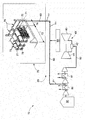
- The sole figure is a schematic diagram of a power plant including a pulse filtration apparatus.
- The detailed description explains embodiments of the invention, together with advantages and features, by way of example with reference to the drawings.
- With reference to the sole figure, a portion of a
power plant 10 is provided and may be, for example, an internal gasification combined cycle (IGCC) power plant. Thepower plant 10 includes apulse filtration apparatus 20 by which filter elements of thepower plant 10 may be cleaned. - The
pulse filtration apparatus 20 includes an air separation unit (ASU) 30 into which a supply of air and other particulate matter is provided and from which a supply of fluid is output. This fluid may include nitrogen (N2). Thepulse filtration apparatus 20 further including agas turbine engine 40. Thegas turbine engine 40 includes acompressor 41 to compress inlet air, which has been filtered by the filter elements of thepower plant 10 as will be described below, acombustor 42 to combust the compressed inlet air along with a supply of fuel and aturbine section 43, which is receptive of products of the combustion for power generation operations. - The
pulse filtration apparatus 20 further includes aconduit 50 by which the fluid output from the ASU 30 (i.e., the nitrogen) is transmitted from theASU 30 to thecombustor 42, atap 60 and afilter housing 70. Thetap 60 includes afirst end 601, which is fluidly coupled to theconduit 50, asecond end 602 opposite thefirst end 601, which is fluidly coupled to components of thefilter housing 70 as will be described below, and amain member 603 fluidly interposed between thefirst end 601 and thesecond end 602. Thetap 60 is configured to remove a quantity of the fluid from theconduit 50 at thefirst end 601 and to transmit the quantity of the fluid along themain member 603 and thesecond end 602 to thefilter housing 70. Thefilter housing 70 is disposed upstream from thecompressor 41 to filter and clean the inlet air. - At least first and second heat transfer elements, such as first and
second intercoolers conduit 50 to cool the fluid transmitted from the ASU 30 to thecombustor 42. In accordance with embodiments, thefirst end 601 of thetap 60 is configured to remove the fluid from theconduit 50 downstream from thefirst intercooler 80 and upstream from thesecond intercooler 81. In addition, anaccumulation unit 90 may be disposed along any one of thefirst end 601, thesecond end 602 or themain member 603 of thetap 60 to accumulate nitrogen therein such that the accumulated nitrogen can be supplied to thefilter housing 70 and to act as a backup system if necessary. In accordance with embodiments, theaccumulation unit 90 supplies the nitrogen to thefilter housing 70 when a predefined quantity of the fluid is unavailable for removal from theconduit 50 and, to this end, theaccumulation unit 90 may be sized for up to about 5 or more days worth of nitrogen supplies. - The components of the
filter housing 70 include ahousing structure 71 including atubesheet 72 having openings formed therein. Thetubesheet 72 extends through thehousing structure 71 to defme a first,dirty air chamber 73 and a second,clean air chamber 74 within thehousing structure 71. Thefilter housing 70 further includes an array offilter elements 75 and an array ofblowpipes 76. Eachfilter element 75 is disposed in a corresponding one of the openings of thetubesheet 72 to filter air flowing from thefirst chamber 73 to thesecond chamber 74 whereby the filtered air can then proceed to thecompressor 41. Eachblowpipe 76 respectively corresponds to one of thefilter elements 75 and is coupled to thesecond end 602 of thetap 60. Eachblowpipe 76 is thus configured to supply the fluid removed from theconduit 50 to a corresponding one of thefilter elements 75. - The
filter housing 70 still further includes acompressed air manifold 77 and amanifold valve assembly 78. Thecompressed air manifold 77 is coupled to eachblowpipe 76 and is thus configured to supply compressed air thereto. Themanifold valve assembly 78 controls the supply of the compressed air to eachblowpipe 76 independently so that eachfilter element 75 can be cleaned independently or in accordance with a predefined cleaning algorithm. - With this construction, the fluid removed from the
conduit 50 and/or the accumulated nitrogen in theaccumulation unit 90 and the compressed air supplied by thecompressed air manifold 77 are injected into thefilter elements 75 at high speed. Dust particles and/or other particulate matter that have collected on the filter media of thefilter elements 75 are thus removed from the filter media such that filtration of the inlet air proceeding to thecompressor 41 can be achieved. - While the invention has been described in detail in connection with only a limited number of embodiments, it should be readily understood that the invention is not limited to such disclosed embodiments. Rather, the invention can be modified to incorporate any number of variations, alterations, substitutions or equivalent arrangements not heretofore described, but which are commensurate with the spirit and scope of the invention. Additionally, while various embodiments of the invention have been described, it is to be understood that aspects of the invention may include only some of the described embodiments. Accordingly, the invention is not to be seen as limited by the foregoing description, but is only limited by the scope of the appended claims.
Claims (13)
- A pulse filtration apparatus (20) of a power plant (10) including an air separation unit (ASU) (30) and a gas turbine engine (40), the apparatus (20) comprising:a conduit (50) to transmit fluid from the ASU (30) to a combustor (42) of the gas turbine engine (40); anda tap (60), including a first end (601) fluidly coupled to the conduit (50), a second end (602) opposite the first end (601) and fluidly coupled to components of a filter housing (70) disposed upstream from a compressor (41) of the gas turbine engine (40) and a main member (603) fluidly interposed between the first and second ends (601) and (602),the tap (60) being configured to remove fluid from the conduit (50) and to transmit the removed fluid to the components of the filter housing (70).
- The apparatus (20) according to claim 1, further comprising first and second intercoolers (80, 81) disposed in series along the conduit (50).
- The apparatus (20) according to claim 2, wherein the tap (60) is configured to remove the fluid from the conduit (50) downstream from the first intercooler (80).
- The apparatus (20) according to any of claims 1 to 3, wherein the fluid removed from the conduit (50) comprises nitrogen (N2).
- The apparatus (20) according to any of claims 1 to 4, further comprising an accumulation unit (90) operably disposed along the tap (60) to accumulate nitrogen therein for supplying nitrogen to the filter housing (70).
- The apparatus (20) according to claim 5, wherein the accumulation unit (90) supplies nitrogen to the filter housing (70) when a predefmed quantity of the fluid is unavailable for removal from the conduit (50).
- The apparatus (20) according to any preceding claim, wherein the components of the filter housing (70) comprise:a housing structure (71) including a tubesheet (72) having openings formed therein, the tubesheet (72) defming first and second chambers (73, 74) within the housing structure (71);an array of filter elements (75) disposed in the tubesheet openings to filter air flowing from the first to the second chambers (73, 74); andan array of blowpipes (76) respectively corresponding to the array of filter elements (75), which are each coupled to the tap(60) to supply the fluid to each of the array of filter elements (75).
- The apparatus (20) according to claim 7, wherein the filter housing (70) further comprises:a compressed air manifold (77) coupled to each of the array of blowpipes (76) to supply compressed air thereto; anda manifold valve assembly (78) to control the supply of the compressed air to each of the array of blowpipes (76) independently.
- A power plant (10), comprising:an air separation unit (ASU) (30);a gas turbine engine (40), including a compressor (41) to compress inlet air, a combustor (42) to combust the compressed inlet air along with fuel and a turbine section (43), which is receptive of products of the combustion for power generation operations; andthe pulse filtration apparatus (20) of any of claims 1 to 8.
- A method of operating a power plant (10), comprising:transmitting a fluid including nitrogen along a conduit (50) from an air separation unit (30) to a combustor (42) of a gas turbine engine (40);removing a quantity of the fluid from the conduit (50); andtransmitting the quantity of the removed fluid to a filter housing (70) disposed upstream from the gas turbine engine (40).
- The method according to claim 10, further comprising cooling the fluid at first and second intercoolers (80,81) disposed in series along the conduit (50),
wherein the removing comprising removing the quantity of the fluid from the conduit (50) downstream from the first intercooler (80). - The method according to claim 10 or 11, further comprising:accumulating nitrogen in an accumulation unit (90); andsupplying the accumulated nitrogen to the filter housing (70).
- The method according to any of claims 10 to 12, further comprising controlling a distribution of the quantity of the removed fluid in the filter housing (70).
Applications Claiming Priority (1)
| Application Number | Priority Date | Filing Date | Title |
|---|---|---|---|
| US13/219,260 US20130047622A1 (en) | 2011-08-26 | 2011-08-26 | Pulse filtration apparatus |
Publications (1)
| Publication Number | Publication Date |
|---|---|
| EP2561914A1 true EP2561914A1 (en) | 2013-02-27 |
Family
ID=46940219
Family Applications (1)
| Application Number | Title | Priority Date | Filing Date |
|---|---|---|---|
| EP12180478A Withdrawn EP2561914A1 (en) | 2011-08-26 | 2012-08-14 | Filtration apparatus with reverse pulse cleaning and power plant including the same |
Country Status (3)
| Country | Link |
|---|---|
| US (1) | US20130047622A1 (en) |
| EP (1) | EP2561914A1 (en) |
| CN (1) | CN102953827A (en) |
Families Citing this family (1)
| Publication number | Priority date | Publication date | Assignee | Title |
|---|---|---|---|---|
| CN110553095B (en) * | 2019-09-03 | 2021-05-18 | 鹤山市文恩卫浴实业有限公司 | Filter element plug-in type washbasin faucet |
Citations (2)
| Publication number | Priority date | Publication date | Assignee | Title |
|---|---|---|---|---|
| US20070204625A1 (en) * | 2006-03-06 | 2007-09-06 | General Electric Company | Methods and systems of variable extraction for compressor protection |
| GB2447744A (en) * | 2007-03-23 | 2008-09-24 | Bha Group Inc | A control system for use with a filter cleaning apparatus |
Family Cites Families (2)
| Publication number | Priority date | Publication date | Assignee | Title |
|---|---|---|---|---|
| US6295838B1 (en) * | 2000-08-16 | 2001-10-02 | Praxair Technology, Inc. | Cryogenic air separation and gas turbine integration using heated nitrogen |
| US20080022855A1 (en) * | 2006-07-26 | 2008-01-31 | Bha Group, Inc. | Filter cleaning system and method |
-
2011
- 2011-08-26 US US13/219,260 patent/US20130047622A1/en not_active Abandoned
-
2012
- 2012-08-14 EP EP12180478A patent/EP2561914A1/en not_active Withdrawn
- 2012-08-24 CN CN2012103058429A patent/CN102953827A/en active Pending
Patent Citations (2)
| Publication number | Priority date | Publication date | Assignee | Title |
|---|---|---|---|---|
| US20070204625A1 (en) * | 2006-03-06 | 2007-09-06 | General Electric Company | Methods and systems of variable extraction for compressor protection |
| GB2447744A (en) * | 2007-03-23 | 2008-09-24 | Bha Group Inc | A control system for use with a filter cleaning apparatus |
Also Published As
| Publication number | Publication date |
|---|---|
| US20130047622A1 (en) | 2013-02-28 |
| CN102953827A (en) | 2013-03-06 |
Similar Documents
| Publication | Publication Date | Title |
|---|---|---|
| JP3975748B2 (en) | Gas turbine equipment and gas turbine cooling method | |
| EP2243534B1 (en) | Filter washing system for gas turbine engines | |
| US8875483B2 (en) | Gas turbine generator set | |
| US20080236150A1 (en) | Turbocharger Cleaning Arrangement | |
| EP1865161B1 (en) | Internal combustion engine and method | |
| JP2016008608A (en) | Debris removal system | |
| EP2494168A2 (en) | System and method for carbon dioxide capture in an air compression and expansion system | |
| EP2561914A1 (en) | Filtration apparatus with reverse pulse cleaning and power plant including the same | |
| RU2458234C1 (en) | Method of operating gas turbine engine | |
| US10159924B2 (en) | Inlet air filtration system with self-cleaning hydrophobic filter bag | |
| US10711694B2 (en) | System and method for de-icing a gas turbine engine | |
| US9200568B1 (en) | Inlet air filtration system with self-cleaning filter bag | |
| AU2012357720B2 (en) | A powerplant comprising a condensed water recovery device | |
| CN110721557A (en) | Device and method for drying and purifying compressed gas | |
| RU2252326C1 (en) | Method of cooling hot units of gas-turbine plants | |
| RU42586U1 (en) | COOLING SYSTEM OF HOT SITES OF GAS-TURBINE INSTALLATIONS | |
| CN217206770U (en) | Gas treatment system combining purification device and air compressor | |
| CN223570260U (en) | Circulating water cooling jetting pipe structure | |
| CN211836790U (en) | Coke oven gas direct combustion type power generation gas precise filtering device | |
| KR200371363Y1 (en) | Equipment for Preventing Back Current Washing Water for Use in Off-Line Washing of Gas Turbine Compressor | |
| RU2405976C1 (en) | Turbo compressor of ice supercharging | |
| CN109026854B (en) | Compressor system capable of performing interstage purification for coke oven gas | |
| CN211118668U (en) | Continuous oil supply lubricating system | |
| CN208980676U (en) | A kind of coke-stove gas processing system | |
| CN119801699A (en) | A diesel engine particulate filter with back-blowing function |
Legal Events
| Date | Code | Title | Description |
|---|---|---|---|
| PUAI | Public reference made under article 153(3) epc to a published international application that has entered the european phase |
Free format text: ORIGINAL CODE: 0009012 |
|
| AK | Designated contracting states |
Kind code of ref document: A1 Designated state(s): AL AT BE BG CH CY CZ DE DK EE ES FI FR GB GR HR HU IE IS IT LI LT LU LV MC MK MT NL NO PL PT RO RS SE SI SK SM TR |
|
| AX | Request for extension of the european patent |
Extension state: BA ME |
|
| 17P | Request for examination filed |
Effective date: 20130827 |
|
| RBV | Designated contracting states (corrected) |
Designated state(s): AL AT BE BG CH CY CZ DE DK EE ES FI FR GB GR HR HU IE IS IT LI LT LU LV MC MK MT NL NO PL PT RO RS SE SI SK SM TR |
|
| 17Q | First examination report despatched |
Effective date: 20140311 |
|
| STAA | Information on the status of an ep patent application or granted ep patent |
Free format text: STATUS: THE APPLICATION IS DEEMED TO BE WITHDRAWN |
|
| 18D | Application deemed to be withdrawn |
Effective date: 20150818 |