EP2561828A1 - Denture attachment - Google Patents
Denture attachment Download PDFInfo
- Publication number
- EP2561828A1 EP2561828A1 EP11771942A EP11771942A EP2561828A1 EP 2561828 A1 EP2561828 A1 EP 2561828A1 EP 11771942 A EP11771942 A EP 11771942A EP 11771942 A EP11771942 A EP 11771942A EP 2561828 A1 EP2561828 A1 EP 2561828A1
- Authority
- EP
- European Patent Office
- Prior art keywords
- sleeve
- magnetic device
- cylindrical portion
- keeper
- denture
- Prior art date
- Legal status (The legal status is an assumption and is not a legal conclusion. Google has not performed a legal analysis and makes no representation as to the accuracy of the status listed.)
- Granted
Links
Images


Classifications
-
- A—HUMAN NECESSITIES
- A61—MEDICAL OR VETERINARY SCIENCE; HYGIENE
- A61C—DENTISTRY; APPARATUS OR METHODS FOR ORAL OR DENTAL HYGIENE
- A61C13/00—Dental prostheses; Making same
- A61C13/225—Fastening prostheses in the mouth
- A61C13/235—Magnetic fastening
Definitions
- the invention relates to a denture attachment that fixes a denture in the mouth using magnetic attractive force.
- the denture attachment includes a magnetic device provided in a denture base to which the denture is fixed and exerting magnetic attractive force, and a keeper provided in an abutment (remaining teeth or implant) and made of a soft magnetic material.
- the denture attachment using the magnetic attractive force (hereinafter referred to as a magnetic attachment) is readily attachable and detachable and allowed to have a slight sideslip on surfaces of the magnetic device and the keeper abutted to each other (attractive surface and attracted surface). Therefore, a lateral force applied to the abutment holding the keeper escapes to protect the abutment.
- magnetic attachments which are devised to deal with an implant increasingly widespread in recent years, are designed to reduce a lateral force applied to the implant. Therefore, the number of required implants to be embedded may be reduced.
- the denture may be disengaged.
- a relatively large lateral force causes the sideslip and relative rotation in a direction where abutment surfaces of the magnetic device and the keeper are pulled away from each other diagonally.
- the magnetic device and the keeper may be shaped to be in mesh with each other so as to avoid the sideslip and the relative rotation.
- Patent Reference 2 An example of the technical option is disclosed in Patent Reference 2.
- a guide ring made of a non-magnetic metal is welded and secured to a circumferential part of a magnetic structure, and the guide ring and a projected portion of the keeper are fitted with each other as illustrated in Fig. 1 .
- Another structural example is to form a projected portion in the keeper and a dented portion in the magnetic structure for the projection to be fitted in so that these portions are fitted with each other.
- the invention provides a denture attachment that accomplishes a lateral force reducing effect and a denture disengagement controlling effect which are particular advantages of any magnetic attachments.
- a denture attachment includes a magnetic device provided in a denture base to exert magnetic attractive force, and a keeper made of a soft magnetic material and provided in an abutment. An attractive surface of the magnetic device and an attracted surface of the keeper are abutted and joined to each other by the magnetic attractive force.
- the magnetic device has a permanent magnet embedded in the magnetic device, and includes a cylindrical portion having a cylindrical outer shape and provided with the attractive surface in a top end of the cylindrical portion, and a flange portion projected radially outward in a rear end of the cylindrical portion.
- the cylindrical portion is mounted with a sleeve from a top end side thereof, the sleeve having flexibility and formed in a cylindrical shape.
- the sleeve has an outer peripheral concavo-convex portion projected radially outward or dented radially inward on an outer peripheral surface, an axial length longer than the cylindrical portion, and one end part projecting above the attractive surface while having the other end part abutted on the flange portion so as to define a keeper housing recess surrounded by the sleeve and the attractive surface.
- the sleeve is configured to be relatively moved in an axial direction of the magnetic device to be inserted into and removed from a top end of the cylindrical portion.
- the magnetic device is configured to be used under the condition that the sleeve is fitted, and an outer side surface of the magnetic device including the outer peripheral concavo-convex portion of the sleeve and the flange portion abutted on the one end part of the sleeve is embedded in the denture base, while having the keeper housing recess exposed.
- the magnetic device of the denture attachment according to the invention in use is embedded in the denture base with the flexible sleeve being mounted on the cylindrical portion.
- the keeper is housed in the keeper housing recess surrounded by the sleeve and the attractive surface, and the attractive surface on the top end of the cylindrical portion and the attracted surface of the keeper are abutted to establish an attractive state by magnetic attractive force. In this state, the sleeve encompasses an outer side surface of the keeper.
- the sleeve is made of a flexible material.
- a lateral force is applied to the denture, therefore, the sideslip between the magnetic device and the keeper relative to each other is allowed by the clearance between the sleeve and the keeper, and elastic deformability of the sleeve, thus providing the effect of reducing the lateral force.
- a relative rotational force is generated in the direction to diagonally force the respective abutment surfaces of the keeper and the magnetic device (attractive surface and attracted surface) apart from each other, such a movement is arrested by the sleeve surrounding the outer side surface of the keeper. This may suppress a chance of disengagement of the denture compared to the related art.
- the magnetic device and the keeper made of metallic materials are basically usable nearly permanently.
- the sleeve made of the flexible material may be worn or degraded. Therefore, it is preferable to replace the sleeve with a new one on a regular basis.
- the sleeve is configured to be relatively moved in the axial direction of the magnetic device so as to be inserted into and removed from the top end of the cylindrical portion. This demands no particular expertise of dental technicians, allowing dentists themselves to replace the sleeve during dental treatments.
- the removal of the magnetic device from the denture base which is a necessary step for replacement of the sleeve, can be handled during periodical adjustments of the denture base performed as a part of dental treatments.
- the outer peripheral concavo-convex portion of the sleeve serves as an undercut in the denture base, helping to securely locate the sleeve in the denture base.
- one end of the sleeve is abutted on the flange portion of the magnetic device so that the flange portion is firmly held between the sleeve and the denture base.
- the magnetic device and the sleeve are thus combined as an integral unit and securely located in the denture base. This prevents the magnetic device or the sleeve from being accidentally disengaged from the denture base when the denture attachment is in use.
- the denture attachment according to the invention is structurally advantageous in that the lateral force and the denture disengagement are effectively controlled by characteristics of the flexible sleeve, and replacement of the used sleeve with a new one to maintain such great advantages can be performed during dental treatments.
- the sleeve of the denture attachment according to the invention is made of any known material with flexibility such as a resin or rubber.
- POM polyacetal
- the outer peripheral concavo-convex portion of the sleeve may be formed in various shapes, for example, a flange-like shape projected radially outward, a groove-like portion dented radially inward, and a combination thereof.
- the cylindrical portion of the magnetic device has a tapered section in a top end-side outer peripheral part of the cylindrical portion, which is diametrically reduced toward the attractive surface, and the sleeve has a chamfered section in an inner peripheral corner part of the one end part.
- These tapered section and chamfered section make it easier for the sleeve to be mounted on the cylindrical portion.
- the keeper has an outer diameter larger than an outer diameter of the cylindrical portion
- the sleeve has a base section covering an outer peripheral surface of the cylindrical portion while having the one end part abutted on the flange portion, and a projection where the keeper housing recess is formed, the projection having an inner diameter larger than an inner diameter of the base section.
- the inner diameter of the base section of the sleeve is adjusted relative to the outer diameter of the cylindrical portion in the magnetic device so that the sleeve can be fitted with an appropriate pressing force. It is preferable to set, for example, an inner diameter difference from about 0.01 mm to 0.3 mm as a press-fitting allowance.
- the press-fitting configuration is not limited even if the press-fitting allowance is omitted or a very small clearance is provided so far as the base section and the sleeve are kept engaged with each other by the assistance of, for example, a surface frictional force.
- the inner diameter of the projected portion of the sleeve is preferably adjusted to a dimension including a minimal clearance corresponding to the outer diameter of the keeper.
- the clearance is preferably set to about 0.05 mm to 1.0 mm.
- the keeper is provided in a top end of an implant embedded in a jawbone. This effectively reduces the lateral force applied to the implant. It is effective for protection of the implant and reduction of the number of required implants.
- a denture attachment 1 according to the embodiment has a magnetic device 2 provided in a denture base 82 of a denture 81 to exert magnetic attractive force, and a keeper 3 made of a soft magnetic material and provided in an implant 83 serving as an abutment.
- a keeper 3 made of a soft magnetic material and provided in an implant 83 serving as an abutment.
- the magnetic device 2 is embedded with a permanent magnet 21 and includes a cylindrical portion 22 having the attractive surface 25 on a top end thereof and formed in a cylindrical outer shape, and a flange portion 23 projected radially outward in a rear end of the cylindrical portion 22.
- the cylindrical portion 22 is mounted with a sleeve 4 having flexibility and formed in a cylindrical shape from a top end side thereof.
- the sleeve 4 is formed in a larger axial length than the cylindrical portion 22 and has an outer peripheral concavo-convex portion 44 projected radially outward and dented radially inward on an outer peripheral surface thereof, and one end part 42 of the sleeve 4 is projected above the attractive surface 25 while having another one end part 41 of the sleeve 4 abutted on the flange portion 23 to form a keeper housing recess 49 surrounded by the sleeve 4 and the attractive surface 25.
- the sleeve 4 is relatively moved in an axial direction of the magnetic device 2 to be inserted into and removed from a top end the cylindrical portion 22.
- the magnetic device 2 is used under the condition that the sleeve 4 is fitted, an outer surface of the magnetic device 2 including the outer peripheral concavo-convex portion 44 of the sleeve 4 and the flange portion 23 abutted on the one end part 41 of the sleeve 4 is embedded in the denture base 82, and the keeper housing recess 49 is exposed.
- the embodiment will be described in further detail.
- the magnetic device 2 has a yoke 20 made of a soft magnetic material and having a recess 210 that houses the permanent magnet 21 exerting the magnetic attractive force, and a disc 28 made of a soft magnetic material and joined with the yoke 20 so as to seal an opening of the recess 210 in which permanent magnet 21 is placed.
- the disc 28 and the yoke 20 are welded to each other in a welding portion 29.
- the yoke 20 has an overall shape similar to a disc shape, and includes the cylindrical portion 22 and the flange portion 23 projected radially outward in a rear end thereof.
- the flange portion 23 has an elliptical outer shape as illustrated in Fig. 4 .
- the flange portion 23 is projected by 0.25 mm corresponding to the length of the major axis of the elliptical shape and by 0.05 mm corresponding to the length of the minor axis of the elliptical shape.
- the elliptical shape is intended to prevent the magnetic device 3 from circumferentially rotating upon embedding in the denture base 82.
- a part of the cylindrical portion 22 mounted with the sleeve 4 has an outer-diametrically equal straight shape. Further, the cylindrical portion 22 has a tapered section 221 diametrically reduced toward the attractive surface 25 in a top end-side outer peripheral part thereof. The tapered section 221 and a chamfered section 412 of the sleeve 4 described later make it easier for the sleeve 4 to be mounted on the cylindrical portion 22 of the magnetic device 2.
- a soft magnetic material 19Cr-2Mo-0.2Ti-Fe
- the disc 28 is also produced from a circular plate made of the soft magnetic material, 19Cr-2Mo-0.2Ti-Fe.
- the welding portion 29 is produced from a non-magnetic material.
- the sleeve 4 has an almost cylindrical overall shape, and includes a base section 401 which covers an outer peripheral surface of the cylindrical portion 22 when the sleeve 4 is mounted on the cylindrical portion 22, and a projection 403 where the keeper housing recess 49 is formed.
- the projection 403 has an inner diameter larger than an inner diameter of the base section 401 in regard to an outer diameter of the keeper 3 larger than an outer diameter of the cylindrical portion 22 of the magnetic device 2.
- a sleeve tapered section 402 having inner and outer diameters gradually changed.
- a sleeve flange section 411 projected radially outward is formed on an outer peripheral surface of the one end part 41 abutted on the flange portion 23 when the base section 401 of the sleeve 4 is fitted to the cylindrical portion 22.
- the outer peripheral concavo-convex portion 44 is formed as a result of radial dimensional changes of the sleeve flange section 411 and the sleeve tapered section 402.
- a chamfered section 412 is formed in an inner peripheral corner part in the one end part 41 of the sleeve 4. This makes it easier for the sleeve 4 to be mounted on the cylindrical portion 22 of the magnetic device 2 together with the tapered section 221 of the cylindrical portion 22.
- notches 416 formed by linearly cutting circular parts to assist a smooth flow of dental resin which will be described later.
- the inner diameter of the base section 401 of the sleeve 4 was set to 4.33 mm ⁇ in view of the press-fitting allowance of 0.07 mm.
- groove sections 417 radially penetrating through are formed.
- the groove sections 417 may be formed at any positions in the circumferential direction, and there may be one groove section 417 or a plurality of groove sections 417.
- the notches 416 serve to prevent the sleeve 4 from rotating similarly to the groove sections 417.
- the groove sections 417 and the notches 416 are formed at circumferentially equal positions, however, these sections may be formed at random positions in the circumferential direction.
- the material used to produce the sleeve 4 is POM (polyacetal).
- the present example used the implant 83 embedded in a jawbone 84 as an abutment and provided the keeper 3 made of a soft magnetic material in the plant 83.
- the outer diameter of the keeper 3 was 4.75 mm ⁇
- the inner diameter of the projection 403 of the sleeve 4 was 5.13 mm ⁇
- a clearance provided between the sleeve 4 and the keeper 3 was 0.38 mm.
- the magnetic device 2 of the denture attachment 1 in use is embedded in the denture base 82 with the flexible sleeve 4 being mounted on the cylindrical portion 22.
- the keeper 3 is housed in the keeper housing recess 49 surrounded by the sleeve 4 and the attractive surface 25, and the attractive surface 25 on the top end of the cylindrical portion 22 and the attracted surface 35 of the keeper 3 are abutted and attracted to each other by magnetic attractive force.
- the sleeve is surrounding the outer side surface of the keeper ( Fig. 2 ).
- the sleeve 4 is made of a flexible material.
- a lateral force is applied to the denture 81, therefore, the sideslip between the magnetic device 2 and the keeper 3 relative to each other is allowed by the clearance between the sleeve 4 and the keeper 3, and elastic deformability of the sleeve 4, thus providing the effect of reducing the lateral force.
- a relative rotational force is generated in the direction to diagonally force the respective abutment surfaces of the keeper 3 and the magnetic device 2 (attractive surface 25 and attracted surface 35) apart from each other, such a movement is arrested by the sleeve 4 surrounding the outer side surface of the keeper 3. This may suppress a chance of disengagement of the denture compared to the related art.
- the magnetic device 2 and the keeper 3 made of metallic materials are basically usable nearly permanently.
- the sleeve 4 made of the flexible material may be worn or degraded. Therefore, it is preferable to replace the sleeve 4 with a new one on a regular basis.
- the sleeve 4 is configured to be relatively moved in an axial direction of the cylindrical portion 22 of the magnetic device 2 so as to be inserted into and removed from the top end of the cylindrical portion 22. This demands no particular expertise of dental technicians, allowing dentists themselves to replace the sleeve during dental treatments.
- the removal of the magnetic device from the denture base which is a necessary step for replacement of the sleeve, can be handled during periodical adjustments of the denture base (rebasing) performed as a part of dental treatments.
- the replacement of the sleeve 4 may be performed as described below.
- a part of the denture base is drilled by a dental tool 91 or the like from the back side of the denture 81 during a dental treatment.
- a dental tool 91 or the like is drilled to reach the magnetic device 2 mounted with the sleeve 4.
- the outer peripheral surface of the sleeve 4 mounted on the reached magnetic device 2 is held by a holding tool 92 separately prepared. Then, the attractive surface 25 of the magnetic device 2 is pushed axially by a bar member 93 having a diameter smaller than the inner diameter of the sleeve 4, and the magnetic device 2 is pulled out from the sleeve 4. The magnetic device and the sleeve 4 are thus easily separable from each other. The sleeve 4 separated from the magnetic device 2 is discarded.
- the magnetic device 2 washed and disinfected is placed on a placement table 94 with the attractive surface 25 directed upward.
- a new sleeve 4 held by the holing tool 95 is moved in the axial direction of the cylindrical portion 22 of the magnetic device 2 and press fitted into the cylindrical portion 22 from the one end part 41.
- the sleeve 4 is successfully fitted.
- the magnetic device 2 mounted with the sleeve 4 is embedded in the denture base 82 of the denture 81.
- the attractive surface 25 of the magnetic device 2 mounted with the sleeve 4 is abutted on the attracted surface 35 of the keeper 3 currently used in the implant 83 of the mouth so that these surfaces are joined through the magnetic attractive force.
- the magnetic device 2 mounted with the sleeve 4 and the keeper 3 are engaged with each other in the same manner as they are in practical use.
- a dental resin 88 is injected into a hole of the denture base 82 of the denture 81 from which the magnetic device 2 has been reached. Then, the denture 81 is mounted on the magnetic device 2, and the magnetic device 2 is inserted into the hole of the denture base 82 so that the dental resin 88 spreads around the magnetic device 2 and the sleeve 4. The inflow of the dental resin 88 is assisted by the notches 416 formed at two circumferential positions in the sleeve flange section 411 of the sleeve 4. The dental resin 88 is cured to complete the rebasing of the denture 81 is completed.
- the magnetic device 2 is provided in a denture base 82 of a new denture 81 in almost the same manner as described above.
- the outer peripheral concavo-convex portion 44 of the sleeve 4 serves as an undercut in the denture base, helping fixation of the sleeve 4 in the denture base 82. Further, the one end part 41 of the sleeve 4 is abutted on the flange portion 23 of the magnetic device 2 so that the flange portion 23 is gripped between the sleeve 4 and the denture base 82.
- the magnetic device 2 and the sleeve 3 thus integrally combined are securely located in the denture base 82, which prevents accidental fall of the magnetic device 2 or the sleeve 4 from the denture base 82 during use.
- Fig. 13 illustrates an example of the denture 81 where the denture attachment 1 according to the embodiment is used.
- the keeper 3 set in the implant is provided at two positions in the mouth.
- the denture 81 is formed by embedding the magnetic device 2 mounted with the sleeve 4 at a position corresponding to the position of the keeper 3.
- the denture 81 may be formed in various shapes that have been conventionally adopted.
- the denture attachment 1 effectively succeeds in reducing the lateral force and preventing the denture from being accidentally disengaged, taking advantage of characteristics of the flexible sleeve 4. Further, replacement of the sleeve with a new one to maintain such great advantages can be easily handled during dental treatments.
Landscapes
- Health & Medical Sciences (AREA)
- Oral & Maxillofacial Surgery (AREA)
- Dentistry (AREA)
- Epidemiology (AREA)
- Life Sciences & Earth Sciences (AREA)
- Animal Behavior & Ethology (AREA)
- General Health & Medical Sciences (AREA)
- Public Health (AREA)
- Veterinary Medicine (AREA)
- Dental Prosthetics (AREA)
Abstract
Description
- The invention relates to a denture attachment that fixes a denture in the mouth using magnetic attractive force.
- In the field of odontotherapy were so far developed various types of denture attachments using magnetic attractive force to readily attach and detach a denture, an example of which is disclosed in
Patent Reference 1. Conventionally, the denture attachment includes a magnetic device provided in a denture base to which the denture is fixed and exerting magnetic attractive force, and a keeper provided in an abutment (remaining teeth or implant) and made of a soft magnetic material. -
- Patent Reference 1: Japanese Patent Application Publication No.
07-136190 - Patent Reference 2: Japanese Patent Application Publication No.
2001-321393 - The denture attachment using the magnetic attractive force (hereinafter referred to as a magnetic attachment) is readily attachable and detachable and allowed to have a slight sideslip on surfaces of the magnetic device and the keeper abutted to each other (attractive surface and attracted surface). Therefore, a lateral force applied to the abutment holding the keeper escapes to protect the abutment. Particularly, magnetic attachments, which are devised to deal with an implant increasingly widespread in recent years, are designed to reduce a lateral force applied to the implant. Therefore, the number of required implants to be embedded may be reduced.
- In consequence of the sideslip generated between the magnetic device and the keeper, the denture may be disengaged. This is conceivable that a relatively large lateral force causes the sideslip and relative rotation in a direction where abutment surfaces of the magnetic device and the keeper are pulled away from each other diagonally. For the purpose of solving the aforementioned problem, the magnetic device and the keeper may be shaped to be in mesh with each other so as to avoid the sideslip and the relative rotation.
- An example of the technical option is disclosed in
Patent Reference 2. In this technique, a guide ring made of a non-magnetic metal is welded and secured to a circumferential part of a magnetic structure, and the guide ring and a projected portion of the keeper are fitted with each other as illustrated inFig. 1 . Another structural example is to form a projected portion in the keeper and a dented portion in the magnetic structure for the projection to be fitted in so that these portions are fitted with each other.
These structures, however, practically disallow any sideslip between the magnetic device and the keeper, thereby losing most of the lateral force reducing effect which is an advantage of any magnetic attachments. These magnetic attachments, therefore, were so far applied to patients whose abutments were in good condition. - To solve these conventional technical problems, the invention provides a denture attachment that accomplishes a lateral force reducing effect and a denture disengagement controlling effect which are particular advantages of any magnetic attachments.
- A denture attachment according to the invention includes a magnetic device provided in a denture base to exert magnetic attractive force, and a keeper made of a soft magnetic material and provided in an abutment. An attractive surface of the magnetic device and an attracted surface of the keeper are abutted and joined to each other by the magnetic attractive force. The magnetic device has a permanent magnet embedded in the magnetic device, and includes a cylindrical portion having a cylindrical outer shape and provided with the attractive surface in a top end of the cylindrical portion, and a flange portion projected radially outward in a rear end of the cylindrical portion. The cylindrical portion is mounted with a sleeve from a top end side thereof, the sleeve having flexibility and formed in a cylindrical shape. The sleeve has an outer peripheral concavo-convex portion projected radially outward or dented radially inward on an outer peripheral surface, an axial length longer than the cylindrical portion, and one end part projecting above the attractive surface while having the other end part abutted on the flange portion so as to define a keeper housing recess surrounded by the sleeve and the attractive surface. The sleeve is configured to be relatively moved in an axial direction of the magnetic device to be inserted into and removed from a top end of the cylindrical portion. The magnetic device is configured to be used under the condition that the sleeve is fitted, and an outer side surface of the magnetic device including the outer peripheral concavo-convex portion of the sleeve and the flange portion abutted on the one end part of the sleeve is embedded in the denture base, while having the keeper housing recess exposed.
- The magnetic device of the denture attachment according to the invention in use is embedded in the denture base with the flexible sleeve being mounted on the cylindrical portion. The keeper is housed in the keeper housing recess surrounded by the sleeve and the attractive surface, and the attractive surface on the top end of the cylindrical portion and the attracted surface of the keeper are abutted to establish an attractive state by magnetic attractive force. In this state, the sleeve encompasses an outer side surface of the keeper.
- The sleeve is made of a flexible material. When a lateral force is applied to the denture, therefore, the sideslip between the magnetic device and the keeper relative to each other is allowed by the clearance between the sleeve and the keeper, and elastic deformability of the sleeve, thus providing the effect of reducing the lateral force.
In the case where a relative rotational force is generated in the direction to diagonally force the respective abutment surfaces of the keeper and the magnetic device (attractive surface and attracted surface) apart from each other, such a movement is arrested by the sleeve surrounding the outer side surface of the keeper. This may suppress a chance of disengagement of the denture compared to the related art. - The magnetic device and the keeper made of metallic materials are basically usable nearly permanently. However, the sleeve made of the flexible material (resin or rubber) may be worn or degraded. Therefore, it is preferable to replace the sleeve with a new one on a regular basis. The sleeve is configured to be relatively moved in the axial direction of the magnetic device so as to be inserted into and removed from the top end of the cylindrical portion. This demands no particular expertise of dental technicians, allowing dentists themselves to replace the sleeve during dental treatments. The removal of the magnetic device from the denture base, which is a necessary step for replacement of the sleeve, can be handled during periodical adjustments of the denture base performed as a part of dental treatments.
- It is unnecessary to use any jig or tool to fit and remove the sleeve to and from the magnetic device. After embedded in the denture base, the outer peripheral concavo-convex portion of the sleeve serves as an undercut in the denture base, helping to securely locate the sleeve in the denture base. Further, one end of the sleeve is abutted on the flange portion of the magnetic device so that the flange portion is firmly held between the sleeve and the denture base. The magnetic device and the sleeve are thus combined as an integral unit and securely located in the denture base. This prevents the magnetic device or the sleeve from being accidentally disengaged from the denture base when the denture attachment is in use.
- As described so far, the denture attachment according to the invention is structurally advantageous in that the lateral force and the denture disengagement are effectively controlled by characteristics of the flexible sleeve, and replacement of the used sleeve with a new one to maintain such great advantages can be performed during dental treatments.
-
-
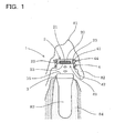
Fig. 1 is an illustration of structural characteristics of a denture attachment according to anembodiment 1 of the invention, in which a magnetic device and a keeper are separated from each other. -
Fig. 2 is an illustration of structural characteristics of the denture attachment according to theembodiment 1, wherein the magnetic device and the keeper are fitted to each other. -
Fig. 3 is a front view of the magnetic device according to theembodiment 1. -
Fig. 4 is a plan view of the magnetic device according to the example 1 (when viewed as illustrated with arrow A ofFig. 3 ). -
Fig. 5 is a sectional view of the magnetic device according to the embodiment 1 (when viewed in cross section cut along B-B ofFig. 4 ). -
Fig. 6 is a front view of a sleeve according to theembodiment 1. -
Fig. 7 is a plan view of the sleeve according to the embodiment 1 (when viewed as illustrated with arrow C ofFig. 6 ). -
Fig. 8 is a sectional view of the sleeve according to the embodiment 1 (when viewed in cross section taken along D-D inFig. 7 ). -
Fig. 9 is an illustration of a method of removing the magnetic device from a denture base according to theembodiment 1. -
Fig. 10 is an illustration of a method of separating the magnetic device and the sleeve from each other according to theembodiment 1. -
Fig. 11 is an illustration of a method of loading the magnetic device with a new sleeve according to theembodiment 1. -
Fig. 12 is an illustration of a method of embedding the magnetic device mounted with the sleeve in the denture base according to theembodiment 1. -
Fig. 13 is an illustration of an example of a denture structure according to theembodiment 1. - The sleeve of the denture attachment according to the invention is made of any known material with flexibility such as a resin or rubber. For example, POM (polyacetal) may be used.
- The outer peripheral concavo-convex portion of the sleeve may be formed in various shapes, for example, a flange-like shape projected radially outward, a groove-like portion dented radially inward, and a combination thereof.
- Preferably, the cylindrical portion of the magnetic device has a tapered section in a top end-side outer peripheral part of the cylindrical portion, which is diametrically reduced toward the attractive surface, and the sleeve has a chamfered section in an inner peripheral corner part of the one end part. These tapered section and chamfered section make it easier for the sleeve to be mounted on the cylindrical portion.
- Preferably, the keeper has an outer diameter larger than an outer diameter of the cylindrical portion, and the sleeve has a base section covering an outer peripheral surface of the cylindrical portion while having the one end part abutted on the flange portion, and a projection where the keeper housing recess is formed, the projection having an inner diameter larger than an inner diameter of the base section. In this case, the whole attractive surface of the magnetic device is easily abutted on the attracted surface of the keeper, and an adsorbing strength is hardly weakened by the sideslip generated between the magnetic device and the keeper.
- Preferably, the inner diameter of the base section of the sleeve is adjusted relative to the outer diameter of the cylindrical portion in the magnetic device so that the sleeve can be fitted with an appropriate pressing force. It is preferable to set, for example, an inner diameter difference from about 0.01 mm to 0.3 mm as a press-fitting allowance.
The press-fitting configuration is not limited even if the press-fitting allowance is omitted or a very small clearance is provided so far as the base section and the sleeve are kept engaged with each other by the assistance of, for example, a surface frictional force.
The inner diameter of the projected portion of the sleeve is preferably adjusted to a dimension including a minimal clearance corresponding to the outer diameter of the keeper. The clearance is preferably set to about 0.05 mm to 1.0 mm. - Preferably, the keeper is provided in a top end of an implant embedded in a jawbone. This effectively reduces the lateral force applied to the implant. It is effective for protection of the implant and reduction of the number of required implants.
- A denture attachment according to an embodiment of the invention is described referring to
Figs. 1 to 12 .
As illustrated inFigs. 1 and2 , adenture attachment 1 according to the embodiment has amagnetic device 2 provided in adenture base 82 of adenture 81 to exert magnetic attractive force, and akeeper 3 made of a soft magnetic material and provided in animplant 83 serving as an abutment. When anattractive surface 25 of themagnetic device 2 and an attractedsurface 35 of thekeeper 3 are abutted on each other, these surfaces are attracted to each other by magnetic attractive force. - As illustrated in
Figs. 1 to 5 , themagnetic device 2 is embedded with apermanent magnet 21 and includes acylindrical portion 22 having theattractive surface 25 on a top end thereof and formed in a cylindrical outer shape, and aflange portion 23 projected radially outward in a rear end of thecylindrical portion 22.
Thecylindrical portion 22 is mounted with asleeve 4 having flexibility and formed in a cylindrical shape from a top end side thereof. Thesleeve 4 is formed in a larger axial length than thecylindrical portion 22 and has an outer peripheral concavo-convex portion 44 projected radially outward and dented radially inward on an outer peripheral surface thereof, and oneend part 42 of thesleeve 4 is projected above theattractive surface 25 while having another oneend part 41 of thesleeve 4 abutted on theflange portion 23 to form akeeper housing recess 49 surrounded by thesleeve 4 and theattractive surface 25. - The
sleeve 4 is relatively moved in an axial direction of themagnetic device 2 to be inserted into and removed from a top end thecylindrical portion 22.
As illustrated in the drawing, themagnetic device 2 is used under the condition that thesleeve 4 is fitted, an outer surface of themagnetic device 2 including the outer peripheral concavo-convex portion 44 of thesleeve 4 and theflange portion 23 abutted on the oneend part 41 of thesleeve 4 is embedded in thedenture base 82, and thekeeper housing recess 49 is exposed.
Hereinafter the embodiment will be described in further detail. - As illustrated in
Figs. 3 to 5 , themagnetic device 2 has ayoke 20 made of a soft magnetic material and having arecess 210 that houses thepermanent magnet 21 exerting the magnetic attractive force, and adisc 28 made of a soft magnetic material and joined with theyoke 20 so as to seal an opening of therecess 210 in whichpermanent magnet 21 is placed. Thedisc 28 and theyoke 20 are welded to each other in awelding portion 29. - The
yoke 20 has an overall shape similar to a disc shape, and includes thecylindrical portion 22 and theflange portion 23 projected radially outward in a rear end thereof. According to the embodiment, theflange portion 23 has an elliptical outer shape as illustrated inFig. 4 . Theflange portion 23 is projected by 0.25 mm corresponding to the length of the major axis of the elliptical shape and by 0.05 mm corresponding to the length of the minor axis of the elliptical shape. The elliptical shape is intended to prevent themagnetic device 3 from circumferentially rotating upon embedding in thedenture base 82. - A part of the
cylindrical portion 22 mounted with thesleeve 4 has an outer-diametrically equal straight shape. Further, thecylindrical portion 22 has a taperedsection 221 diametrically reduced toward theattractive surface 25 in a top end-side outer peripheral part thereof. The taperedsection 221 and achamfered section 412 of thesleeve 4 described later make it easier for thesleeve 4 to be mounted on thecylindrical portion 22 of themagnetic device 2. - To produce the
yoke 20, a soft magnetic material, 19Cr-2Mo-0.2Ti-Fe, was subjected to the cutting work. Thedisc 28 is also produced from a circular plate made of the soft magnetic material, 19Cr-2Mo-0.2Ti-Fe. Thewelding portion 29 is produced from a non-magnetic material. - As illustrated in
Figs. 6 to 8 , thesleeve 4 has an almost cylindrical overall shape, and includes abase section 401 which covers an outer peripheral surface of thecylindrical portion 22 when thesleeve 4 is mounted on thecylindrical portion 22, and aprojection 403 where thekeeper housing recess 49 is formed. Theprojection 403 has an inner diameter larger than an inner diameter of thebase section 401 in regard to an outer diameter of thekeeper 3 larger than an outer diameter of thecylindrical portion 22 of themagnetic device 2. Between thebase section 401 and theprojection 403 is formed a sleeve taperedsection 402 having inner and outer diameters gradually changed. - A
sleeve flange section 411 projected radially outward is formed on an outer peripheral surface of the oneend part 41 abutted on theflange portion 23 when thebase section 401 of thesleeve 4 is fitted to thecylindrical portion 22. The outer peripheral concavo-convex portion 44 is formed as a result of radial dimensional changes of thesleeve flange section 411 and the sleeve taperedsection 402. - A
chamfered section 412 is formed in an inner peripheral corner part in the oneend part 41 of thesleeve 4. This makes it easier for thesleeve 4 to be mounted on thecylindrical portion 22 of themagnetic device 2 together with the taperedsection 221 of thecylindrical portion 22. In two circumferential positions of thesleeve flange section 411 were providednotches 416 formed by linearly cutting circular parts to assist a smooth flow of dental resin which will be described later. The inner diameter of thebase section 401 of thesleeve 4 was set to 4.33 mmφ in view of the press-fitting allowance of 0.07 mm. - At two positions in a top end of the
projection 403 of thesleeve 4,groove sections 417 radially penetrating through are formed. When the dental resin is injected through thegroove sections 417 and solidified, thesleeve 4 is surely prevented from circumferentially rotating in thedenture base 82. Thegroove sections 417 may be formed at any positions in the circumferential direction, and there may be onegroove section 417 or a plurality ofgroove sections 417. Thenotches 416 serve to prevent thesleeve 4 from rotating similarly to thegroove sections 417. According to the embodiment, thegroove sections 417 and thenotches 416 are formed at circumferentially equal positions, however, these sections may be formed at random positions in the circumferential direction.
The material used to produce thesleeve 4 is POM (polyacetal). - As illustrated in
Figs. 1 and2 , the present example used theimplant 83 embedded in ajawbone 84 as an abutment and provided thekeeper 3 made of a soft magnetic material in theplant 83. The outer diameter of thekeeper 3 was 4.75 mmφ, the inner diameter of theprojection 403 of thesleeve 4 was 5.13 mmφ, and a clearance provided between thesleeve 4 and thekeeper 3 was 0.38 mm. - Hereinafter, operational advantages of the
denture attachment 1 according to the embodiment will be described.
As illustrated inFigs. 1 and2 , themagnetic device 2 of thedenture attachment 1 in use is embedded in thedenture base 82 with theflexible sleeve 4 being mounted on thecylindrical portion 22. Then, thekeeper 3 is housed in thekeeper housing recess 49 surrounded by thesleeve 4 and theattractive surface 25, and theattractive surface 25 on the top end of thecylindrical portion 22 and the attractedsurface 35 of thekeeper 3 are abutted and attracted to each other by magnetic attractive force. In the described state, the sleeve is surrounding the outer side surface of the keeper (Fig. 2 ). - The
sleeve 4 is made of a flexible material. When a lateral force is applied to thedenture 81, therefore, the sideslip between themagnetic device 2 and thekeeper 3 relative to each other is allowed by the clearance between thesleeve 4 and thekeeper 3, and elastic deformability of thesleeve 4, thus providing the effect of reducing the lateral force.
In the case where a relative rotational force is generated in the direction to diagonally force the respective abutment surfaces of thekeeper 3 and the magnetic device 2 (attractive surface 25 and attracted surface 35) apart from each other, such a movement is arrested by thesleeve 4 surrounding the outer side surface of thekeeper 3. This may suppress a chance of disengagement of the denture compared to the related art. - The
magnetic device 2 and thekeeper 3 made of metallic materials are basically usable nearly permanently. However, thesleeve 4 made of the flexible material may be worn or degraded. Therefore, it is preferable to replace thesleeve 4 with a new one on a regular basis. Thesleeve 4 is configured to be relatively moved in an axial direction of thecylindrical portion 22 of themagnetic device 2 so as to be inserted into and removed from the top end of thecylindrical portion 22. This demands no particular expertise of dental technicians, allowing dentists themselves to replace the sleeve during dental treatments. The removal of the magnetic device from the denture base, which is a necessary step for replacement of the sleeve, can be handled during periodical adjustments of the denture base (rebasing) performed as a part of dental treatments. - The replacement of the
sleeve 4 may be performed as described below.
As illustrated inFig. 9 , a part of the denture base is drilled by adental tool 91 or the like from the back side of thedenture 81 during a dental treatment. For example, an area shown with a broken line A is drilled to reach themagnetic device 2 mounted with thesleeve 4. - As illustrated in
Fig. 10 , the outer peripheral surface of thesleeve 4 mounted on the reachedmagnetic device 2 is held by a holdingtool 92 separately prepared. Then, theattractive surface 25 of themagnetic device 2 is pushed axially by abar member 93 having a diameter smaller than the inner diameter of thesleeve 4, and themagnetic device 2 is pulled out from thesleeve 4. The magnetic device and thesleeve 4 are thus easily separable from each other. Thesleeve 4 separated from themagnetic device 2 is discarded. - As illustrated in
Fig. 11 , themagnetic device 2 washed and disinfected is placed on a placement table 94 with theattractive surface 25 directed upward. Anew sleeve 4 held by the holingtool 95 is moved in the axial direction of thecylindrical portion 22 of themagnetic device 2 and press fitted into thecylindrical portion 22 from the oneend part 41. When the oneend part 41 is abutted on theflange portion 23, thesleeve 4 is successfully fitted. - Next, the
magnetic device 2 mounted with thesleeve 4 is embedded in thedenture base 82 of thedenture 81. As illustrated inFig. 12 , theattractive surface 25 of themagnetic device 2 mounted with thesleeve 4 is abutted on the attractedsurface 35 of thekeeper 3 currently used in theimplant 83 of the mouth so that these surfaces are joined through the magnetic attractive force. As illustrated in the drawing, themagnetic device 2 mounted with thesleeve 4 and thekeeper 3 are engaged with each other in the same manner as they are in practical use. - As illustrated in the drawing, a
dental resin 88 is injected into a hole of thedenture base 82 of thedenture 81 from which themagnetic device 2 has been reached. Then, thedenture 81 is mounted on themagnetic device 2, and themagnetic device 2 is inserted into the hole of thedenture base 82 so that thedental resin 88 spreads around themagnetic device 2 and thesleeve 4. The inflow of thedental resin 88 is assisted by thenotches 416 formed at two circumferential positions in thesleeve flange section 411 of thesleeve 4.
Thedental resin 88 is cured to complete the rebasing of thedenture 81 is completed.
Themagnetic device 2 is provided in adenture base 82 of anew denture 81 in almost the same manner as described above. - In the
denture 81 thus obtained, the outer peripheral concavo-convex portion 44 of thesleeve 4 serves as an undercut in the denture base, helping fixation of thesleeve 4 in thedenture base 82. Further, the oneend part 41 of thesleeve 4 is abutted on theflange portion 23 of themagnetic device 2 so that theflange portion 23 is gripped between thesleeve 4 and thedenture base 82. Themagnetic device 2 and thesleeve 3 thus integrally combined are securely located in thedenture base 82, which prevents accidental fall of themagnetic device 2 or thesleeve 4 from thedenture base 82 during use. -
Fig. 13 illustrates an example of thedenture 81 where thedenture attachment 1 according to the embodiment is used. Thekeeper 3 set in the implant is provided at two positions in the mouth. Thedenture 81 is formed by embedding themagnetic device 2 mounted with thesleeve 4 at a position corresponding to the position of thekeeper 3. Thedenture 81 may be formed in various shapes that have been conventionally adopted. - As described so far, the
denture attachment 1 according to the embodiment effectively succeeds in reducing the lateral force and preventing the denture from being accidentally disengaged, taking advantage of characteristics of theflexible sleeve 4. Further, replacement of the sleeve with a new one to maintain such great advantages can be easily handled during dental treatments.
Claims (4)
- A denture attachment, comprising:a magnetic device provided in a denture base to exert magnetic attractive force; anda keeper made of a soft magnetic material and provided in an abutment, wherein:an attractive surface of the magnetic device and an attracted surface of the keeper are abutted and joined to each other by the magnetic attractive force;the magnetic device has a permanent magnet embedded in the magnetic device, and includes a cylindrical portion having a cylindrical outer shape and provided with the attractive surface in a top end of the cylindrical portion, and a flange portion projected radially outward in a rear end of the cylindrical portion;the cylindrical portion is mounted with a sleeve from a top end side thereof, the sleeve having flexibility and formed in a cylindrical shape;the sleeve has an outer peripheral concavo-convex portion projected radially outward or dented radially inward on an outer peripheral surface, an axial length longer than the cylindrical portion, and one end part projecting above the attractive surface while having the other end part abutted on the flange portion so as to define a keeper housing recess surrounded by the sleeve and the attractive surface;the sleeve is configured to be relatively moved in an axial direction of the magnetic device to be inserted into and removed from a top end of the cylindrical portion; andthe magnetic device is configured to be used under the condition that the sleeve is fitted, and an outer side surface of the magnetic device including the outer peripheral concavo-convex portion of the sleeve and the flange portion abutted on the one end part of the sleeve is embedded in the denture base, while having the keeper housing recess exposed.
- The denture attachment according to claim 1, wherein:the cylindrical portion of the magnetic device has a tapered section in a top end-side outer peripheral part of the cylindrical portion, the tapered section being diametrically reduced toward the attractive surface; andthe sleeve has a chamfered section in an inner peripheral corner part of the one end part.
- The denture attachment according to claim 1 or 2, wherein:the keeper has an outer diameter larger than an outer diameter of the cylindrical portion; andthe sleeve has a base section covering an outer peripheral surface of the cylindrical portion while having the one end part abutted on the flange portion, and a projection where the keeper housing recess is formed, the projection having an inner diameter larger than an inner diameter of the base section.
- The denture attachment according to any one of claims 1 to 3, wherein the keeper is provided in a top end of an implant embedded in a jawbone.
Applications Claiming Priority (2)
| Application Number | Priority Date | Filing Date | Title |
|---|---|---|---|
| JP2010095783A JP5408019B2 (en) | 2010-04-19 | 2010-04-19 | Denture attachment |
| PCT/JP2011/059374 WO2011132607A1 (en) | 2010-04-19 | 2011-04-15 | Denture attachment |
Publications (3)
| Publication Number | Publication Date |
|---|---|
| EP2561828A1 true EP2561828A1 (en) | 2013-02-27 |
| EP2561828A4 EP2561828A4 (en) | 2015-07-01 |
| EP2561828B1 EP2561828B1 (en) | 2017-06-07 |
Family
ID=44834127
Family Applications (1)
| Application Number | Title | Priority Date | Filing Date |
|---|---|---|---|
| EP11771942.7A Not-in-force EP2561828B1 (en) | 2010-04-19 | 2011-04-15 | Denture attachment |
Country Status (4)
| Country | Link |
|---|---|
| US (1) | US8591233B2 (en) |
| EP (1) | EP2561828B1 (en) |
| JP (1) | JP5408019B2 (en) |
| WO (1) | WO2011132607A1 (en) |
Families Citing this family (6)
| Publication number | Priority date | Publication date | Assignee | Title |
|---|---|---|---|---|
| KR101515899B1 (en) * | 2014-12-31 | 2015-05-06 | 신원덴탈(주) | A magnetic implant overdenture with a mounting ring |
| KR101701122B1 (en) * | 2015-08-03 | 2017-02-02 | 신원덴탈(주) | Magnet attachment impression cap for overdeuture magnet keeper transfer |
| KR102327517B1 (en) * | 2019-11-29 | 2021-11-16 | 신태운 | Magnetic Implants for Overdenture |
| KR102198237B1 (en) * | 2020-01-14 | 2021-01-05 | (주) 코웰메디 | Cenemtless dental implant using elastic bushing |
| CN113616364A (en) * | 2021-08-30 | 2021-11-09 | 张普华 | Novel take artificial tooth of sucking disc abrasionproof teethridge |
| EP4465918A4 (en) * | 2022-02-18 | 2025-12-24 | Metro North Hospital And Health Services | MAGNETICALLY HELD DENTURE |
Family Cites Families (11)
| Publication number | Priority date | Publication date | Assignee | Title |
|---|---|---|---|---|
| JPH07136190A (en) | 1993-11-19 | 1995-05-30 | Aichi Steel Works Ltd | Implants fixed to the edentulous jaw |
| JP3658441B2 (en) * | 1996-02-26 | 2005-06-08 | 譲治 田中 | Cap type magnetic attachment |
| JPH10229992A (en) * | 1997-02-19 | 1998-09-02 | Joji Tanaka | Improved dental magnetic attachment and impression collecting method using magnetic attachment |
| JP4320373B2 (en) * | 1999-05-26 | 2009-08-26 | 愛知製鋼株式会社 | Denture attachment and its keeper |
| JP2001321393A (en) | 2000-03-09 | 2001-11-20 | Aichi Steel Works Ltd | Denture attachment |
| JP2002102258A (en) | 2000-09-29 | 2002-04-09 | Aichi Steel Works Ltd | Denture attachment for bar type implant |
| JP2002282281A (en) | 2001-03-22 | 2002-10-02 | Aichi Steel Works Ltd | Denture attachment |
| JP2002325778A (en) | 2001-05-01 | 2002-11-12 | Aichi Steel Works Ltd | Denture attachment |
| CN1284515C (en) | 2001-12-27 | 2006-11-15 | 爱知制钢株式会社 | Magnetic fastening device for dental prostheses |
| CN1750798B (en) | 2003-02-17 | 2013-06-26 | 爱知制钢株式会社 | Denture magnetic attachment |
| JP3861922B2 (en) * | 2003-09-05 | 2006-12-27 | 愛知製鋼株式会社 | Denture attachment, denture and manufacturing method thereof |
-
2010
- 2010-04-19 JP JP2010095783A patent/JP5408019B2/en active Active
-
2011
- 2011-04-15 EP EP11771942.7A patent/EP2561828B1/en not_active Not-in-force
- 2011-04-15 WO PCT/JP2011/059374 patent/WO2011132607A1/en not_active Ceased
- 2011-04-15 US US13/642,303 patent/US8591233B2/en not_active Expired - Fee Related
Non-Patent Citations (1)
| Title |
|---|
| See references of WO2011132607A1 * |
Also Published As
| Publication number | Publication date |
|---|---|
| US8591233B2 (en) | 2013-11-26 |
| EP2561828B1 (en) | 2017-06-07 |
| JP2011224109A (en) | 2011-11-10 |
| US20130034831A1 (en) | 2013-02-07 |
| JP5408019B2 (en) | 2014-02-05 |
| EP2561828A4 (en) | 2015-07-01 |
| WO2011132607A1 (en) | 2011-10-27 |
Similar Documents
| Publication | Publication Date | Title |
|---|---|---|
| US8591233B2 (en) | Denture attachment | |
| US11547528B2 (en) | Positioning and installing surgical drilling devices and related devices and systems | |
| EP3119346B1 (en) | Positioning and installing surgical drilling devices and related devices and systems | |
| KR100331589B1 (en) | False tooth attachment and method and spacer for fixing the same | |
| KR20150123262A (en) | Dental prosthetic arrangement and dental prosthetic system | |
| US9421072B2 (en) | Vibratory instrument with an interchangeable tool | |
| EP3372192A1 (en) | Dental blank positioning device | |
| KR100535250B1 (en) | A keeper for a dental magnetic attachment | |
| CN106870567B (en) | Bearing seal and drawing jig | |
| JP3861922B2 (en) | Denture attachment, denture and manufacturing method thereof | |
| CN102198019A (en) | Impression cap for a dental implant | |
| EP2901962A1 (en) | Magnetic field generation device for promoting bone growth, implant device using same, and dental prosthesis for protecting implant | |
| JP2010220635A (en) | Chuck device of dental handpiece | |
| JP4898950B1 (en) | Locking member for fixing screw of implant | |
| JP3675259B2 (en) | Keeper for denture attachment | |
| CN1750798B (en) | Denture magnetic attachment | |
| EP2556805B1 (en) | Root cap with a removable keeper tray having an opening | |
| JP2001037781A (en) | Denture attachment and its keeper and magnet device | |
| JP2015119822A (en) | Magnet structure removal jig | |
| JP2003033375A (en) | Dental magnetic attachment and housing pattern | |
| EP1457166A1 (en) | Micronail and method for dental use | |
| JPH06225890A (en) | Magnetic crown prosthesis | |
| KR20200094458A (en) | Apparatus for placing dental implant structure | |
| JP2004150499A (en) | E type retaining ring | |
| JP2016202234A (en) | Stent manufacturing apparatus and manufacturing method |
Legal Events
| Date | Code | Title | Description |
|---|---|---|---|
| PUAI | Public reference made under article 153(3) epc to a published international application that has entered the european phase |
Free format text: ORIGINAL CODE: 0009012 |
|
| 17P | Request for examination filed |
Effective date: 20121025 |
|
| AK | Designated contracting states |
Kind code of ref document: A1 Designated state(s): AL AT BE BG CH CY CZ DE DK EE ES FI FR GB GR HR HU IE IS IT LI LT LU LV MC MK MT NL NO PL PT RO RS SE SI SK SM TR |
|
| DAX | Request for extension of the european patent (deleted) | ||
| RA4 | Supplementary search report drawn up and despatched (corrected) |
Effective date: 20150602 |
|
| RIC1 | Information provided on ipc code assigned before grant |
Ipc: A61C 8/00 20060101ALI20150527BHEP Ipc: A61C 13/235 20060101AFI20150527BHEP |
|
| RIC1 | Information provided on ipc code assigned before grant |
Ipc: A61C 13/235 20060101AFI20161201BHEP |
|
| GRAP | Despatch of communication of intention to grant a patent |
Free format text: ORIGINAL CODE: EPIDOSNIGR1 |
|
| STAA | Information on the status of an ep patent application or granted ep patent |
Free format text: STATUS: GRANT OF PATENT IS INTENDED |
|
| INTG | Intention to grant announced |
Effective date: 20170119 |
|
| GRAS | Grant fee paid |
Free format text: ORIGINAL CODE: EPIDOSNIGR3 |
|
| GRAA | (expected) grant |
Free format text: ORIGINAL CODE: 0009210 |
|
| STAA | Information on the status of an ep patent application or granted ep patent |
Free format text: STATUS: THE PATENT HAS BEEN GRANTED |
|
| AK | Designated contracting states |
Kind code of ref document: B1 Designated state(s): AL AT BE BG CH CY CZ DE DK EE ES FI FR GB GR HR HU IE IS IT LI LT LU LV MC MK MT NL NO PL PT RO RS SE SI SK SM TR |
|
| REG | Reference to a national code |
Ref country code: GB Ref legal event code: FG4D |
|
| GRAA | (expected) grant |
Free format text: ORIGINAL CODE: 0009210 |
|
| REG | Reference to a national code |
Ref country code: CH Ref legal event code: EP Ref country code: AT Ref legal event code: REF Ref document number: 898639 Country of ref document: AT Kind code of ref document: T Effective date: 20170615 |
|
| REG | Reference to a national code |
Ref country code: IE Ref legal event code: FG4D |
|
| REG | Reference to a national code |
Ref country code: DE Ref legal event code: R096 Ref document number: 602011038552 Country of ref document: DE |
|
| REG | Reference to a national code |
Ref country code: NL Ref legal event code: FP |
|
| REG | Reference to a national code |
Ref country code: LT Ref legal event code: MG4D |
|
| PG25 | Lapsed in a contracting state [announced via postgrant information from national office to epo] |
Ref country code: NO Free format text: LAPSE BECAUSE OF FAILURE TO SUBMIT A TRANSLATION OF THE DESCRIPTION OR TO PAY THE FEE WITHIN THE PRESCRIBED TIME-LIMIT Effective date: 20170907 Ref country code: HR Free format text: LAPSE BECAUSE OF FAILURE TO SUBMIT A TRANSLATION OF THE DESCRIPTION OR TO PAY THE FEE WITHIN THE PRESCRIBED TIME-LIMIT Effective date: 20170607 Ref country code: ES Free format text: LAPSE BECAUSE OF FAILURE TO SUBMIT A TRANSLATION OF THE DESCRIPTION OR TO PAY THE FEE WITHIN THE PRESCRIBED TIME-LIMIT Effective date: 20170607 Ref country code: GR Free format text: LAPSE BECAUSE OF FAILURE TO SUBMIT A TRANSLATION OF THE DESCRIPTION OR TO PAY THE FEE WITHIN THE PRESCRIBED TIME-LIMIT Effective date: 20170908 Ref country code: FI Free format text: LAPSE BECAUSE OF FAILURE TO SUBMIT A TRANSLATION OF THE DESCRIPTION OR TO PAY THE FEE WITHIN THE PRESCRIBED TIME-LIMIT Effective date: 20170607 Ref country code: LT Free format text: LAPSE BECAUSE OF FAILURE TO SUBMIT A TRANSLATION OF THE DESCRIPTION OR TO PAY THE FEE WITHIN THE PRESCRIBED TIME-LIMIT Effective date: 20170607 |
|
| REG | Reference to a national code |
Ref country code: AT Ref legal event code: MK05 Ref document number: 898639 Country of ref document: AT Kind code of ref document: T Effective date: 20170607 |
|
| PG25 | Lapsed in a contracting state [announced via postgrant information from national office to epo] |
Ref country code: LV Free format text: LAPSE BECAUSE OF FAILURE TO SUBMIT A TRANSLATION OF THE DESCRIPTION OR TO PAY THE FEE WITHIN THE PRESCRIBED TIME-LIMIT Effective date: 20170607 Ref country code: RS Free format text: LAPSE BECAUSE OF FAILURE TO SUBMIT A TRANSLATION OF THE DESCRIPTION OR TO PAY THE FEE WITHIN THE PRESCRIBED TIME-LIMIT Effective date: 20170607 Ref country code: SE Free format text: LAPSE BECAUSE OF FAILURE TO SUBMIT A TRANSLATION OF THE DESCRIPTION OR TO PAY THE FEE WITHIN THE PRESCRIBED TIME-LIMIT Effective date: 20170607 Ref country code: BG Free format text: LAPSE BECAUSE OF FAILURE TO SUBMIT A TRANSLATION OF THE DESCRIPTION OR TO PAY THE FEE WITHIN THE PRESCRIBED TIME-LIMIT Effective date: 20170907 |
|
| PG25 | Lapsed in a contracting state [announced via postgrant information from national office to epo] |
Ref country code: EE Free format text: LAPSE BECAUSE OF FAILURE TO SUBMIT A TRANSLATION OF THE DESCRIPTION OR TO PAY THE FEE WITHIN THE PRESCRIBED TIME-LIMIT Effective date: 20170607 Ref country code: RO Free format text: LAPSE BECAUSE OF FAILURE TO SUBMIT A TRANSLATION OF THE DESCRIPTION OR TO PAY THE FEE WITHIN THE PRESCRIBED TIME-LIMIT Effective date: 20170607 Ref country code: CZ Free format text: LAPSE BECAUSE OF FAILURE TO SUBMIT A TRANSLATION OF THE DESCRIPTION OR TO PAY THE FEE WITHIN THE PRESCRIBED TIME-LIMIT Effective date: 20170607 Ref country code: AT Free format text: LAPSE BECAUSE OF FAILURE TO SUBMIT A TRANSLATION OF THE DESCRIPTION OR TO PAY THE FEE WITHIN THE PRESCRIBED TIME-LIMIT Effective date: 20170607 Ref country code: SK Free format text: LAPSE BECAUSE OF FAILURE TO SUBMIT A TRANSLATION OF THE DESCRIPTION OR TO PAY THE FEE WITHIN THE PRESCRIBED TIME-LIMIT Effective date: 20170607 |
|
| PG25 | Lapsed in a contracting state [announced via postgrant information from national office to epo] |
Ref country code: IT Free format text: LAPSE BECAUSE OF FAILURE TO SUBMIT A TRANSLATION OF THE DESCRIPTION OR TO PAY THE FEE WITHIN THE PRESCRIBED TIME-LIMIT Effective date: 20170607 Ref country code: SM Free format text: LAPSE BECAUSE OF FAILURE TO SUBMIT A TRANSLATION OF THE DESCRIPTION OR TO PAY THE FEE WITHIN THE PRESCRIBED TIME-LIMIT Effective date: 20170607 Ref country code: IS Free format text: LAPSE BECAUSE OF FAILURE TO SUBMIT A TRANSLATION OF THE DESCRIPTION OR TO PAY THE FEE WITHIN THE PRESCRIBED TIME-LIMIT Effective date: 20171007 Ref country code: PL Free format text: LAPSE BECAUSE OF FAILURE TO SUBMIT A TRANSLATION OF THE DESCRIPTION OR TO PAY THE FEE WITHIN THE PRESCRIBED TIME-LIMIT Effective date: 20170607 |
|
| REG | Reference to a national code |
Ref country code: DE Ref legal event code: R097 Ref document number: 602011038552 Country of ref document: DE |
|
| PLBE | No opposition filed within time limit |
Free format text: ORIGINAL CODE: 0009261 |
|
| STAA | Information on the status of an ep patent application or granted ep patent |
Free format text: STATUS: NO OPPOSITION FILED WITHIN TIME LIMIT |
|
| PG25 | Lapsed in a contracting state [announced via postgrant information from national office to epo] |
Ref country code: DK Free format text: LAPSE BECAUSE OF FAILURE TO SUBMIT A TRANSLATION OF THE DESCRIPTION OR TO PAY THE FEE WITHIN THE PRESCRIBED TIME-LIMIT Effective date: 20170607 |
|
| 26N | No opposition filed |
Effective date: 20180308 |
|
| PG25 | Lapsed in a contracting state [announced via postgrant information from national office to epo] |
Ref country code: SI Free format text: LAPSE BECAUSE OF FAILURE TO SUBMIT A TRANSLATION OF THE DESCRIPTION OR TO PAY THE FEE WITHIN THE PRESCRIBED TIME-LIMIT Effective date: 20170607 |
|
| PG25 | Lapsed in a contracting state [announced via postgrant information from national office to epo] |
Ref country code: MC Free format text: LAPSE BECAUSE OF FAILURE TO SUBMIT A TRANSLATION OF THE DESCRIPTION OR TO PAY THE FEE WITHIN THE PRESCRIBED TIME-LIMIT Effective date: 20170607 |
|
| REG | Reference to a national code |
Ref country code: CH Ref legal event code: PL |
|
| REG | Reference to a national code |
Ref country code: BE Ref legal event code: MM Effective date: 20180430 |
|
| GBPC | Gb: european patent ceased through non-payment of renewal fee |
Effective date: 20180415 |
|
| REG | Reference to a national code |
Ref country code: IE Ref legal event code: MM4A |
|
| PG25 | Lapsed in a contracting state [announced via postgrant information from national office to epo] |
Ref country code: LU Free format text: LAPSE BECAUSE OF NON-PAYMENT OF DUE FEES Effective date: 20180415 |
|
| PG25 | Lapsed in a contracting state [announced via postgrant information from national office to epo] |
Ref country code: BE Free format text: LAPSE BECAUSE OF NON-PAYMENT OF DUE FEES Effective date: 20180430 Ref country code: GB Free format text: LAPSE BECAUSE OF NON-PAYMENT OF DUE FEES Effective date: 20180415 Ref country code: CH Free format text: LAPSE BECAUSE OF NON-PAYMENT OF DUE FEES Effective date: 20180430 Ref country code: LI Free format text: LAPSE BECAUSE OF NON-PAYMENT OF DUE FEES Effective date: 20180430 |
|
| PG25 | Lapsed in a contracting state [announced via postgrant information from national office to epo] |
Ref country code: IE Free format text: LAPSE BECAUSE OF NON-PAYMENT OF DUE FEES Effective date: 20180415 Ref country code: FR Free format text: LAPSE BECAUSE OF NON-PAYMENT OF DUE FEES Effective date: 20180430 |
|
| PG25 | Lapsed in a contracting state [announced via postgrant information from national office to epo] |
Ref country code: MT Free format text: LAPSE BECAUSE OF NON-PAYMENT OF DUE FEES Effective date: 20180415 |
|
| PG25 | Lapsed in a contracting state [announced via postgrant information from national office to epo] |
Ref country code: TR Free format text: LAPSE BECAUSE OF FAILURE TO SUBMIT A TRANSLATION OF THE DESCRIPTION OR TO PAY THE FEE WITHIN THE PRESCRIBED TIME-LIMIT Effective date: 20170607 |
|
| PG25 | Lapsed in a contracting state [announced via postgrant information from national office to epo] |
Ref country code: HU Free format text: LAPSE BECAUSE OF FAILURE TO SUBMIT A TRANSLATION OF THE DESCRIPTION OR TO PAY THE FEE WITHIN THE PRESCRIBED TIME-LIMIT; INVALID AB INITIO Effective date: 20110415 Ref country code: PT Free format text: LAPSE BECAUSE OF FAILURE TO SUBMIT A TRANSLATION OF THE DESCRIPTION OR TO PAY THE FEE WITHIN THE PRESCRIBED TIME-LIMIT Effective date: 20170607 |
|
| PG25 | Lapsed in a contracting state [announced via postgrant information from national office to epo] |
Ref country code: CY Free format text: LAPSE BECAUSE OF FAILURE TO SUBMIT A TRANSLATION OF THE DESCRIPTION OR TO PAY THE FEE WITHIN THE PRESCRIBED TIME-LIMIT Effective date: 20170607 Ref country code: MK Free format text: LAPSE BECAUSE OF NON-PAYMENT OF DUE FEES Effective date: 20170607 |
|
| PG25 | Lapsed in a contracting state [announced via postgrant information from national office to epo] |
Ref country code: AL Free format text: LAPSE BECAUSE OF FAILURE TO SUBMIT A TRANSLATION OF THE DESCRIPTION OR TO PAY THE FEE WITHIN THE PRESCRIBED TIME-LIMIT Effective date: 20170607 |
|
| P01 | Opt-out of the competence of the unified patent court (upc) registered |
Effective date: 20230413 |
|
| PGFP | Annual fee paid to national office [announced via postgrant information from national office to epo] |
Ref country code: NL Payment date: 20240418 Year of fee payment: 14 |
|
| PGFP | Annual fee paid to national office [announced via postgrant information from national office to epo] |
Ref country code: DE Payment date: 20240418 Year of fee payment: 14 |
|
| REG | Reference to a national code |
Ref country code: DE Ref legal event code: R119 Ref document number: 602011038552 Country of ref document: DE |
|
| REG | Reference to a national code |
Ref country code: NL Ref legal event code: MM Effective date: 20250501 |
|
| PG25 | Lapsed in a contracting state [announced via postgrant information from national office to epo] |
Ref country code: DE Free format text: LAPSE BECAUSE OF NON-PAYMENT OF DUE FEES Effective date: 20251104 |
|
| PG25 | Lapsed in a contracting state [announced via postgrant information from national office to epo] |
Ref country code: NL Free format text: LAPSE BECAUSE OF NON-PAYMENT OF DUE FEES Effective date: 20250501 |